

Page 1

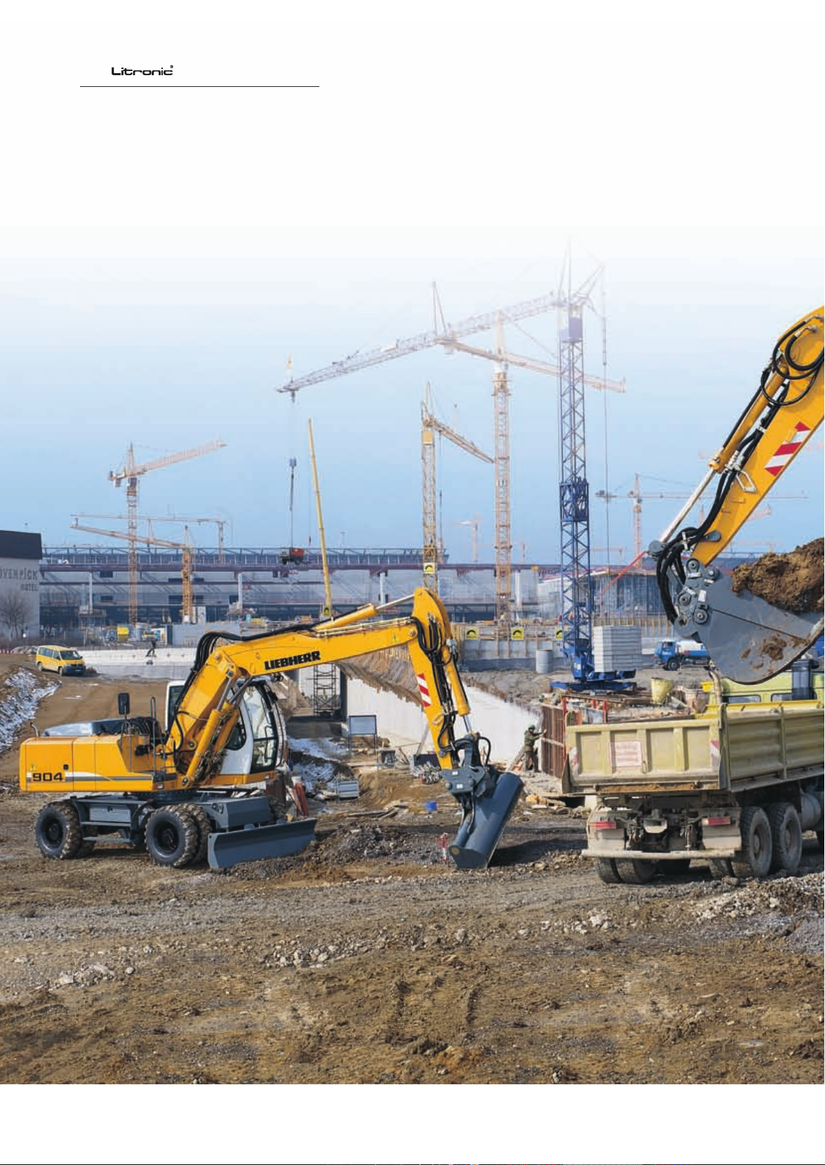
Wheeled Excavator
A 900 C
Operating Weight: 17,400 - 19,600 kg
Engine Output: 95 kW / 129 HP
Bucket Capacity: 0.32 - 0.95 m³
Page 2
2
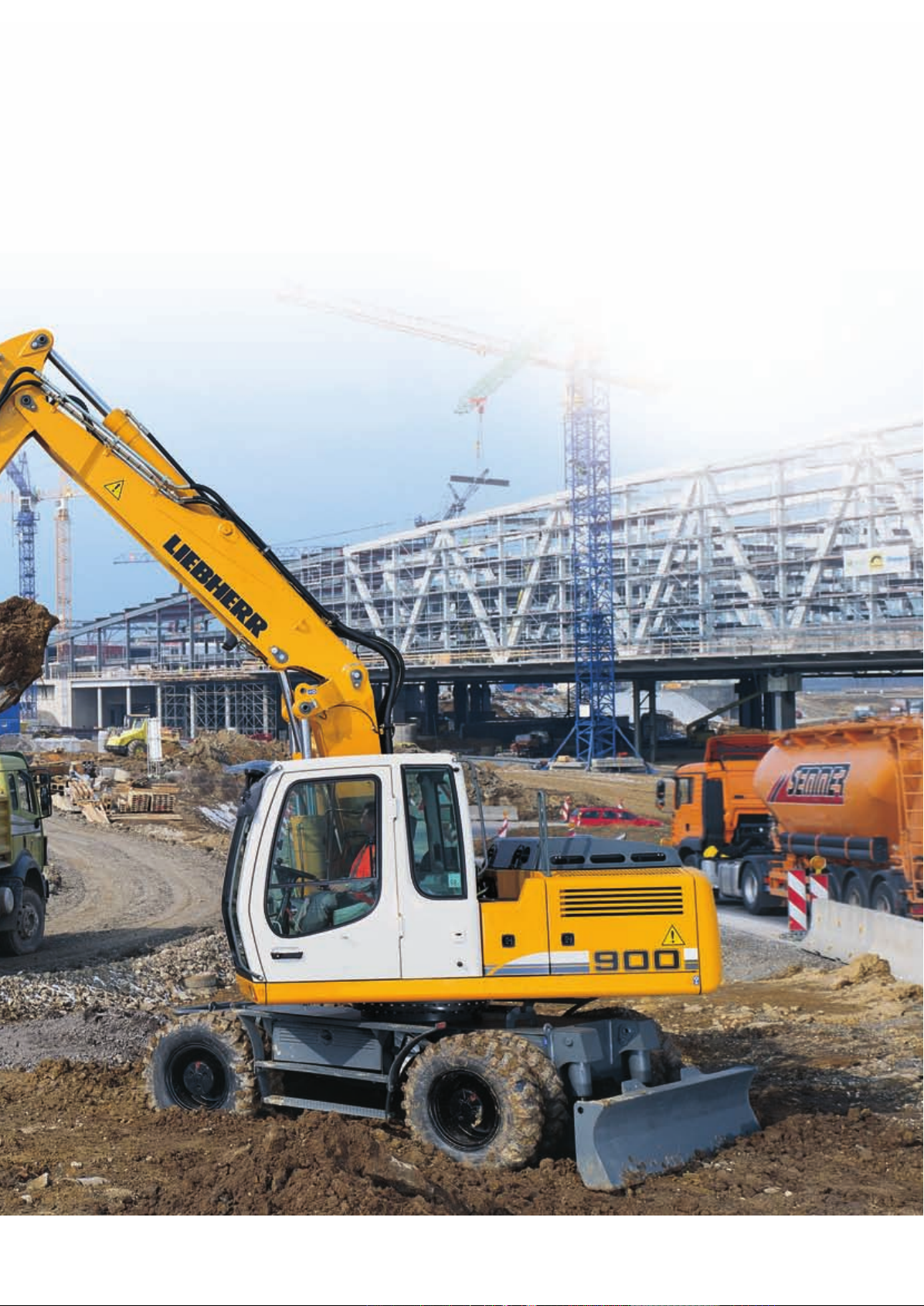
A 900 C
Operating Weight: 17,400 - 19,600 kg
Engine Output: 95 kW / 129 HP
Bucket Capacity: 0.32 - 0.95 m³
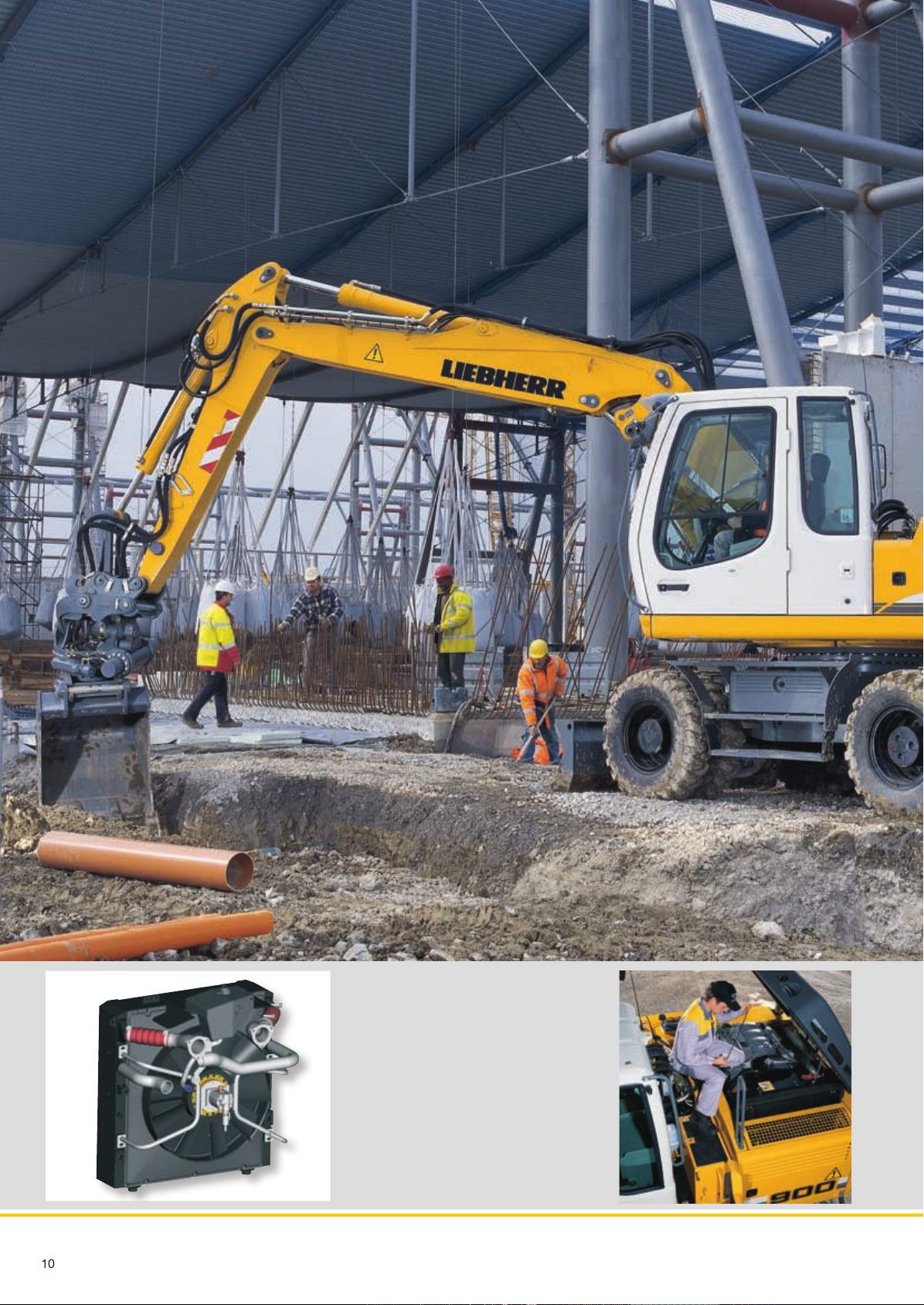
A 900 C Litronic
Page 3
3
Reliability
Liebherr hydraulic excavators have been designed and
built to withstand the toughest of conditions at the building site. Their rugged design, high-tensile materials and
individual components ensure maximum availability and
long life-expectancy.
Performance
Liebherr wheel excavators have been designed for maximum productivity. Maximum digging performances, high
lift capacities and quick working cycles are prerequisite
for effi cient building site operation, and a wide variety of
attachments optimize every excavator application.
Comfort
Largely dimensioned and ergonomically designed, the
Liebherr excavator cab features an operator’s seat which
can be individually adjusted, as well as clearly arranged
control instruments and ideal all-round view. Automatic
air-conditioning guarantees an optimum temperature in
the Liebherr Feel-Good cab at all times.
Economy
The Liebherr-Litronic-System increases machine performance, reduces fuel consumption and minimises service
and maintenance costs. Due to Liebherr’s well- balanced
range, the ideal machine can always be selected to suit
every application.
A 900 C Litronic
Page 4
4
A 900 C Litronic
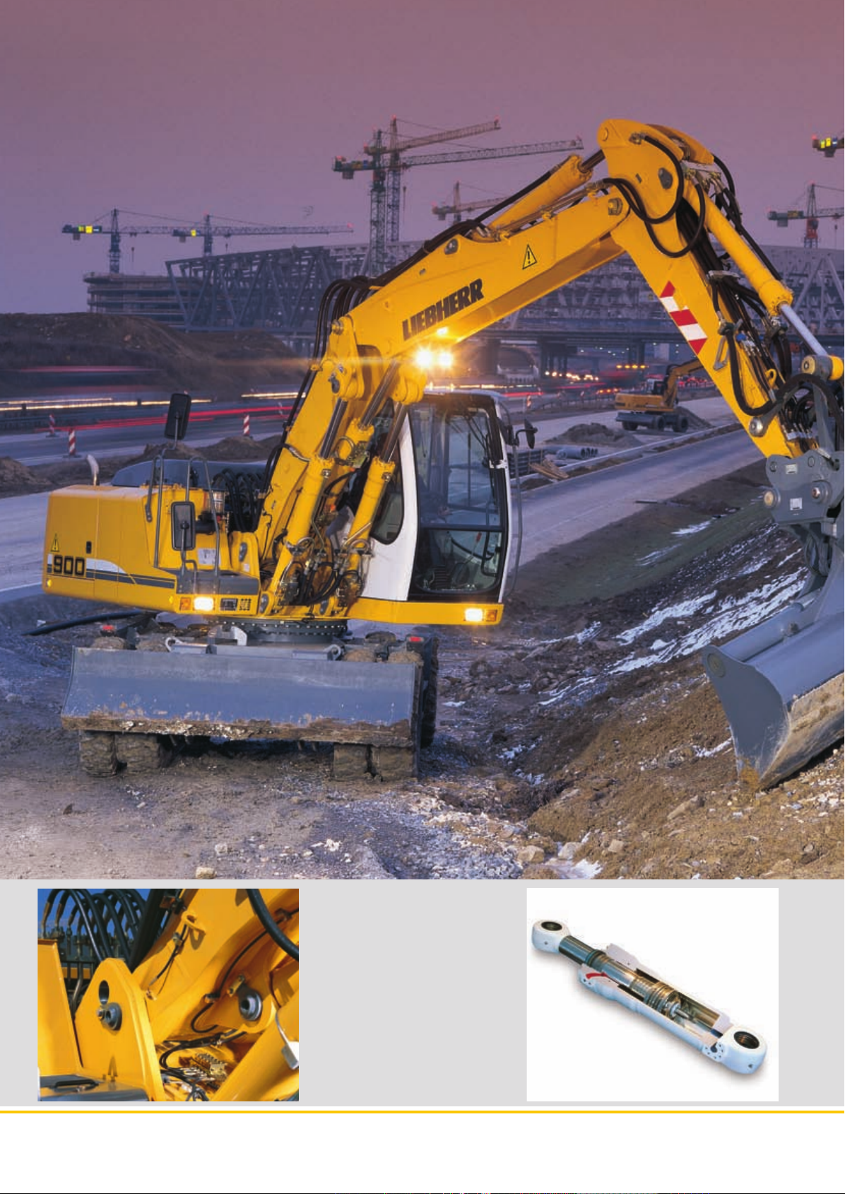
Features
• High-tensile steel plates in highstress areas for the toughest of
applications
• Well-thought-out and secure bearings
for attachments and cylinders
• Maximum resistance, even when
lifting heavy loads
Page 5
5
Reliability
Liebherr construction machinery is proven all over the world every day on the
most diverse of building sites. Many years of experience as the world’s largest
manufacturer of rubber-tyre excavators, continuous development and the introduction of the latest technology are evident in every machine, guaranteeing absolute safety during applications. With its rugged design, and featuring
Liebherr components, the Liebherr hydraulic excavators have been designed
for extremely long life-expectancy.
Quality in detail
Liebherr components
Functional safety
Rugged attachments
Working attachment
Components such as engine, hydraulic cylinders,
swing gear and electric parts have been specially
designed, tested and manufactured by Liebherr
for construction machinery. Parts including engines and pumps for example, are already being
synchronized with each other as early as the
construction phase, yielding a constant standard
of quality.
Safety-orientated components, fi tted as standard,
allow high availability.
The operator can thus concentrate fully on the
task at hand, due to the integrated on-board electronics performing a constant balancing of predefi ned set data.
Filtering of metallic fi lings by the magnetic rod, fi tted in the hydraulic system as standard, increases
life-expectancy of the hydraulic components and
the oil.
The durable attachments have been designed for
the toughest of applications. All components are
optimised to the FEM methods and the hoist cylinders feature bearings on both sides.
Liebherr hydraulic cylinders
• Specifi c size for each machine
• High-grade surface coating of
the piston rods
• All Liebherr cylinders feature
special long-life sealing systems
• Shock absorption at both sides
in the working cylinders
Piping
The hydraulic lines are arranged optimally to safeguard against damage. The electric cabling is
made with high-grade materials, thus guaranteeing a reliable supply to the consumer.
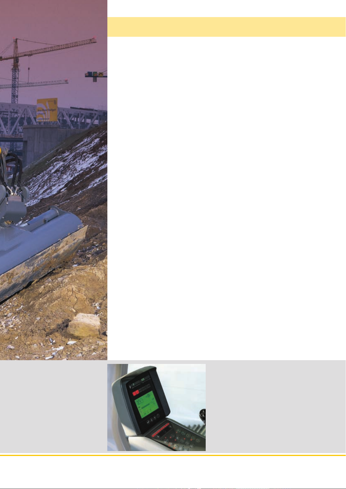
Functional safety
• Essential operating data is stored and can
be recalled at any time.
• Control and monitoring functions increase
functional safety of the machine.
• Four fi xed working modes for output discharge
facilitate an effective and effi cient operation:
– Eco-Mode: for high output at big fuel savings
– Power-Mode: for heavy-duty digging-and loading
performance under severe conditions
– Lift-Mode: for precise handling of heavy loads
– Fine-Mode: for fi ne control at precision work
A 900 C Litronic
Page 6
6
A 900 C Litronic
Liebherr diesel engine
• Long life-expectancy, expansive cylinder
capacity and increased weight
• According to level IIIA / Tier 3
• Specially designed for construction
machinery operation
• Oil supply even with extreme tilt angle
Page 7
7
Performance
Liebherr wheel excavators have been designed for maximum productivity. Perfectly harmonized, the Liebherr-developed and Liebherr-manufactured components including diesel engine, hydraulic pump and motor, as well as swing
gear and cylinders, guarantee maximum performance. Tremendous digging
and breakout forces, extensive lifting capacities and quick working and travel
movements are thus resulted.
Innovative solutions
Intelligent
undercarriage
Multitude of
attachments
Extensive lifting
capacities
High productivity
Quick working cycles
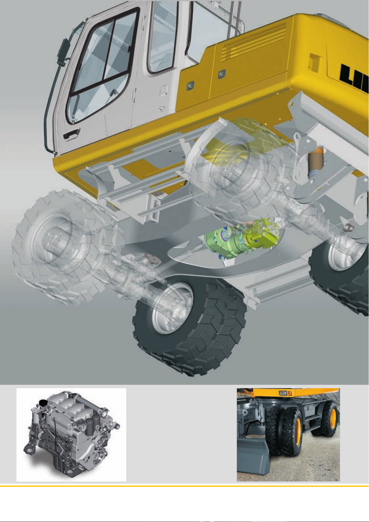
The entire travel drive unit is integrated in the sturdy
undercarriage. Intelligently built and robust in service, the undercarriage offers the travel drive unit
the best possible protection from debris, stones
and soil. Its advantages are perfect all-terrain compatibility and extremely high ground clearance.
Liebherr provide an individual, application-related
range of diverse attachments. Hydraulic booms,
adjustable both in height and offset positions, as
well as standard and offset-adjustable goosenecks,
can be combined with different sticks.
Canalization and the lifting of pipes are everyday
tasks for rubber-tyre excavators. These requirements are endorsed via an intelligent concept of
uppercarriage sectioning together with the positioning of the Liebherr engine, mounted at a transversal angle directly in front of the counterweight.
Separate hoist cylinder bearing points at the upper end of the basic boom also increase the lifting
capacities considerably.
High swing torque – attained as a result of the
Liebherr swing ring featuring internal teeth and
swing drive, specially designed to increase the
torque.
Rugged undercarriage
• Various undercarriage designs featuring welded, durable outriggers
allow safe positioning, optimum stability, and long life-expectancy of the
machine for every application.
• Prop-up blade / dozing blade in
box-type design – only two bearing
points for high torsional resistance
• Optional protection system for blade
cylinders
Performance without
compromise
Maximum performance and maximum forces are
available to the operator at all times.
Litronic
• Increases productivity of the
excavator
• Reduces fuel consumption
• Reduces service costs and eases
operation
• Allows maximum sensitivity and as
many overlapping movements as are
required
A 900 C Litronic
Page 8
8
A 900 C Litronic
Large-sized cab
• Adjustable steering column
• Operator’s seat, adjustable in height and
can also be adapted to the individual weight
of the operator.
• Consoles with or without possibility
of horizontal adjustment.
• Large roof window
• Sun blinds
Page 9
9
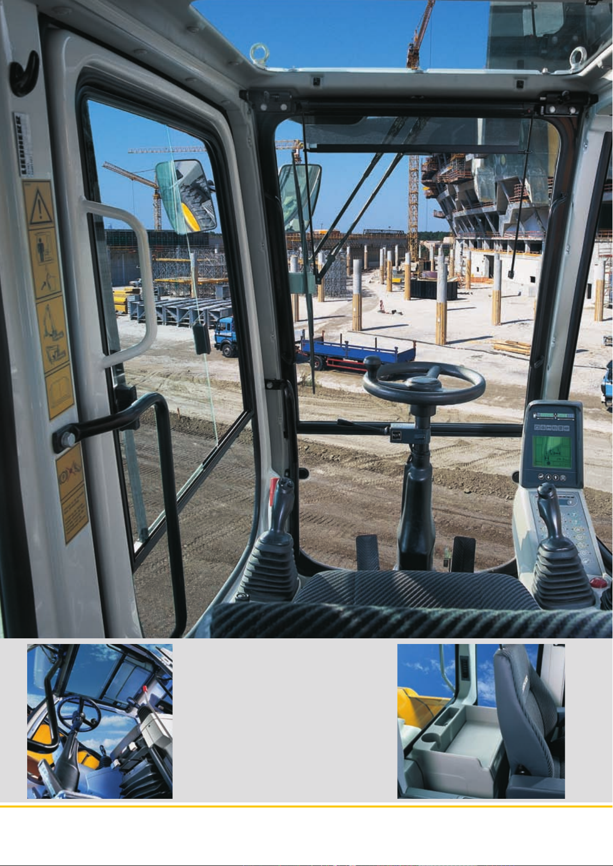
Comfort
The excavator operator is provided with an ergonomically-arranged working
area within Liebherr hydraulic excavator cabs. All switches and functions are
logically laid out, and operator’s seat, steering column and consoles can be
adjusted individually. Conditioning and concentration can thus be maintained
throughout the entire working day, guaranteeing constant, maximum productivity of the operator.
Mobile comfort
Easy access
Optimum visibility
Pleasant surroundings
Maintenance features
Easy maintenance
Ease of operation
Easy access
Wide steps, ergonomically-positioned handles
and adjustable steering column allow an easy access into the Liebherr operator’s cab.
A well-thought-out design of the uppercarriage,
featuring large glass panels and rounded edges,
increase overall visibility and guarantees a safe
overview of the entire working area.
Reduced engine speed together with elaborate
sound insulation, as well as optimised hydraulic
components, allow a comfortable noise level both
inside and out. The noise level is comparable with
that of a diesel car.
Semi-Automatical Central lubrication for swing
gear and main parts of the attachment.
A shut-off valve, fi tted to the hydraulic tank as
standard, disconnects the system and guarantees
ease of maintenance to the hydraulic system.
Large maintenance fl aps allow comfortable and
safe access to all maintenance points.
Storage compartment –
Everything has its place
• Suffi cient storage space for a commercially-approved cooler box behind the
operator’s seat
• Drinks holder and storage compartment in operator’s cab
• Large storage box behind the
operator’s cab
• Two standard tool boxes in the
undercarriage
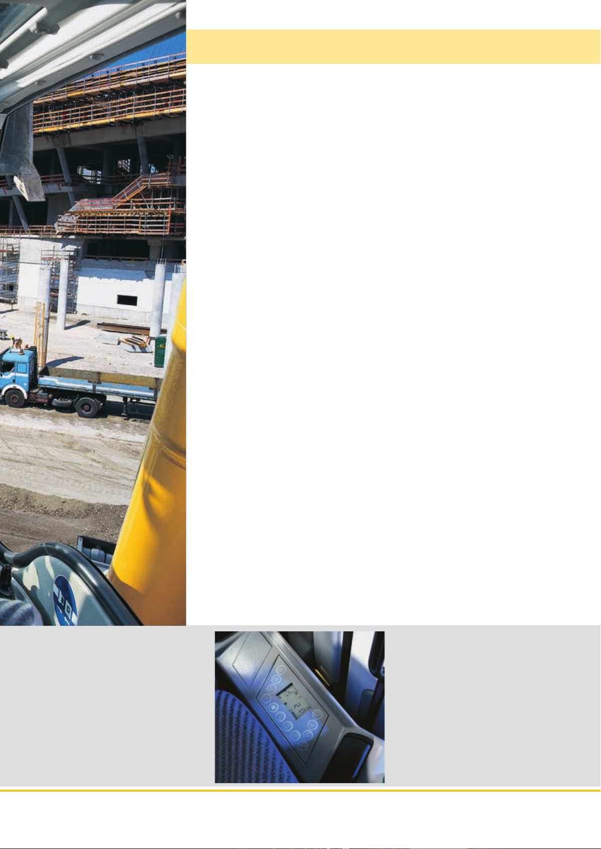
Fully-automatic air-conditioning system
• The air-conditioning system, fi tted as
standard, offers the same comfort as that
of a regular car
• Two sensors for precise temperature
regulation
• Ventilation fl aps are controlled via keys
• Reheat function for quick dehumidifying /
defrosting of the windshield
A 900 C Litronic
Page 10
10
A 900 C Litronic
Hydrostatic fan drive
• Accelerated warm-up period
• Guaranteed constant oil quality as a
result of constant oil temperature
• Increased life-expectancy of drive
components
• The fan only runs at the output required, thus conserving fuel and reducing the noise level considerably
Page 11

11
Economy
Liebherr offer a wide range of models, guaranteeing optimum suitability for
every application. Easy access to components, as well as the proven service
offer allows maintenance tasks to be performed in the shortest of times, thus
reducing operating costs considerably.
Low operating costs
Solid Liebherr Engine
Maximum power of the engine is generated even
when running at minimum speed. This allows the
necessary output without limitation, whereby the
torque which is available is ample for the level required, resulting in high productivity with low consumption.
Automatic idle
If no working or travel movements are being performed, the shiftable function reduces the engine
speed to idle, which in turn reduces fuel consumption and emission levels.
Intelligent hydraulic
management
The state-of-the-art hydraulic system allows conversion of the maximum engine output into high
force or speed, as required. The maximum possible forces are available at all times.
Investment for the future
Extensive service offer
Proven service offers assured by our service personnel trained directly at the manufacturing plants,
and endorsed by our tight-knit network of dealers, provide services in all required areas. Direct
contact to Liebherr is guaranteed via complete integration of all service points in our own Liebherr
logistics system. Electronic access to our global
spare-parts management allows a 98% availability of spare-parts 24 hours a day.
Service-orientated
• Service points of the engine – such
as fi lter or fi lling amount displays
are easily accessible and can be
easily reached from the maintenance platform
• The magnetic rod on the hydraulic
oil return fl ow increases life-expectancy of the oil
• semi-Automatical Central lubrication for swing gear and main parts
of the attachment allowing quicker
maintenance
High resale values
Liebherr excavators are built with high-grade materials and quality production to provide a longterm operational life-span, thus guaranteeing maximum resale values.
Modular quick-change system
made by Liebherr
• Likufi x – connects all hydraulically
mounted tools without having to leave
the operator’s cab, maximum productivity due to tool change being performed in a matter of seconds
• The suitable digging tool for every
application. Your machine is a multifunctional tool carrier and will pay for
itself very quickly indeed.
• Mechanic and hydraulic Liebherr
quick-change adapter
A 900 C Litronic
Page 12

Technical Data
Engine
Rating per ISO 9249
������������������������������
Model
�������������������������������
Type
Bore/Stroke
Displacement
Engine operation
Cooling system
Air cleaner
Fuel tank
�����������������������
�������������������������
Engine idling
Electrical system
Voltage
����������������������
Batteries
Alternator
���������
����������������
�������������
��������������
����������������
��������������������
��������������������
�������������������
Hydraulic System
Hydraulic pump
Max. flow
Max. hydr. pressure
Hydraulic pump
regulation and control
Hydraulic tank capacity
Hydraulic
Filtration
Cooling system
�����������������������������
Modes
LIFT
FINE
ECO
POWER
Super-Finish
RPM adjustment
����������������
�������������������
system capacity
��������������������������
����������������
���������������������������
��������������������������
��������������������������
���������������������
��������������������
���������������
Hydraulic Controls
Power distribution
Control type
Attachment and
swing
Travel
Additional functions
Option
������������������������
������������������������
�����������������������������
������������
����������
95 kW (129 HP) at 1,800 RPM
Liebherr D 934 S according to level IIIA / Tier 3
4 cylinder in-line
122/136 mm
6.4 l
4-stroke diesel
unit pump system
turbo-charged and after-cooled
reduced emissions
water-cooled and integrated motor oil
cooler
dry-type air cleaner with pre-cleaner,
primary and safety elements
290 l
sensor controlled
24 V
2 x 110 Ah/12 V
three phase current 28 V/80 A
Liebherr, variable displacement, swash-
plate pump
300 l/min.
����
350 bar
�������
Liebherr-Synchron-Comfort-system (LSC)
with electronic horsepower regulation,
pressure cut-off, load sensing and torque
controlled swing drive priority
�����
175 l
��
max. 290 l
one main return filter with integrated partial
micro filtration (5 µm)
compact cooler, consisting of a water
cooler, sandwiched with hydraulic oil
cooler, fuel cooler and after-cooler cores
and hydrostatically driven fan
can also be adjusted by the operator to
adjust engine and hydraulic performance to
match job conditions (Note: All modes pro-
vide full max. power)
for precise lifting tasks
for precision work at high speed i.e.
grading
for most economic performance at best
environmental conditions
for max. output
additional operator adjustable work speed
function for further increased feathering.
Applies to all modes and all control func-
tions
stepless adjustment of engine output via
rpm
via control valve with integrated safety
valves, simultaneous and independent
operation of travel drive, swing drive and
work
proportional via joystick levers
proportional via foot pedal
via switch and/or proportional foot pedals
Liebherr-Proportional-Controls, propor-
tionally acting transmitters on the joysticks
for additional hydraulic functions
Swing Drive
�������������������������������
Drive
Transmission
Swing ring
�����������������������
Swing speed
Swing torque
Holding brake
�����������������������������
Option
�������������������
��������������������
�������������������
������������������
Liebherr swashplate motor with torque
control and integrated brake valve
Liebherr compact planetary reduction gear
Liebherr sealed single race ball bearing
swing ring, internal teeth
0 – 9.0 RPM
42 kNm
wet discs (spring applied – pressure
released)
pedal controlled positioning brake
Operator’s Cab
���������������������������������
Cab
resiliently mounted, sound insulated, tinted
windows, front window stores overhead,
door with sliding window, large roof win-
Operator’s seat
����������������
dow, sun visor
fully adjustable, shockabsorbing suspen-
sion, adjustable to operator’s weight and
Joysticks
Monitoring
�������������������������
�����������������������
size, 6-way adjustable Liebherr seat
integrated into adjustable seat consoles
menu driven query of current operating
conditions via the LCD display. Automatic
monitoring, display, warning (acoustical
and optical signal) and saving machine
data, for example, engine overheating, low
Air conditioning
����������������
engine oil pressure or low hydraulic oil level
standard air conditioning, combined cooler/
heater, additional dust filter in fresh air/
recirculated
Noise emission
ISO 6396
2000/14/EC
�������������������������
���������������������
LpA (inside cab) = 72 dB(A)
LWA (surround noise) = 99 dB(A)
Sound level in correspondence with “Blue Angel” guidelines.
Undercarriage
�������������������������������
Drive
Transmission
Travel speed
�������������������
��������������������
variable flow swashplate motor with auto-
matic brake valve
oversized two speed power shift trans-
mission with additional creeper speed
0 – 2.5 km/h (creeper speed off road)
0 – 5.0 km/h (off road)
0 – 9.0 km/h (creeper speed on road)
0 – 20.0 km/h (road travel)
�������������������������������
Axles
����������������������������
Brakes
0 – 30.0 km/h Speeder (Option)
32 t excavator axles; automatic or operator
controlled front axle oscillation lock
steering and rigid axle with wet, mainte-
nance-free multi disc brakes with minimized
backlash. Spring applied/pressure released
Stabilization
���������������������
parking brake integrated into gear box
stabilizing blade (adjustable during travel
for dozing)
2-point outriggers
stabilizing blade, front + 2 pt. outriggers,
rear
�����������������������������
Option
4-point outriggers
EW (extra wide gauge) undercarriage
Attachment
Hydraulic cylinders
������������������������������
Pivots
Lubrication
�����������
����������������������
Liebherr cylinders with special seal system.
Shock absorption
sealed, low maintenance
Liebherr semi-automatic central lubrication
system
12 A 900 C Litronic
Page 13

Dimensions
E
D
W
U2
T2
M
L
U1
V
X
I2 J2
B
B2
T1
I3J3
T3
H
K
T1
U3
A
C
Q
B
B1
B
B3
B1
mm
A 2,550
B 2,550
1)
B
2,750
B1 3,690
B2 2,550
1)
B2
2,750
B3 2,550
C 3,160
D 2,260
E 2,330
H 2,465
I2 425
I3 380
J2 605
J3 585
K 1,235
L 2,540
M 1,100
Q 360
T1 1,050
T2 1,225
T3 1,155
U1 4,390
U2 4,575
U3 4,740
1)
= EW-Undercarriage
E = Tail radius
Tires 10.00-20
Stick Hydr. Adjustable Gooseneck Boom
Boom 3.60 m 5.00 m
stabil. 2 pt. blade 4 pt. stabil. 2 pt. blade 4 pt.
blade outr. + 2 pt. outr. blade outr. + 2 pt. outr.
outr. outr.
m mm mm mm mm mm mm mm mm
V 2.25 6,250 6,200 6,200 6,200 5,850 5,800 5,800 5,800
2.45 5,950 5,900 5,900 5,900 5,450 5,400 5,400 5,400
2.65 5,850 5,800 5,800 5,800 5,350 5,250 5,650 5,550*
W 2.25 3,050 3,050 3,050 3,050 3,150 3,150 3,150 3,150
2.45 3,050 3,050 3,050 3,050 3,050 3,050 3,050 3,050
2.65 3,100 3,100 3,100 3,100 3,100 3,100 3,100 3,100*
X 2.25 8,700 8,650 8,650 8,650 8,500 8,400 8,400 8,400
2.45 8,700 8,650 8,650 8,650 8,450 8,400 8,400 8,400
2.65 8,700 8,650 8,650 8,650 8,500 8,400 8,800 8,700*
Stick Adjustable Up/Down Adjustable Offset
Plus Offset Boom Boom 4.90 m
3.60 m
stabil. 2 pt. blade 4 pt. stabil. 2 pt. blade 4 pt.
blade outr. + 2 pt. outr. blade outr. + 2 pt. outr.
outr. outr.
m mm mm mm mm mm mm mm mm
V 2.25 6,250 6,150 6,100 6,150 6,250 6,150 6,150 6,150
2.45 6,000 5,900 5,900 5,900 5,700 5,650 5,650 5,650
2.65 5,900 5,800 5,800 5,800 5,300 5,250 5,650 5,500
W 2.25 3,050 3,050 3,050 3,050 3,150 3,150 3,150 3,150
2.45 3,050 3,050 3,050 3,050 3,050 3,050 3,050 3,050
2.65 3,150 3,150 3,150 3,150 3,000 3,000 3,000 3,000
X 2.25 8,700 8,650 8,650 8,650 8,350 8,300 8,300 8,300
2.45 8,700 8,650 8,650 8,650 8,400 8,300 8,300 8,300
2.65 8,700 8,650 8,650 8,650 8,400 8,300 8,750 8,600*
Dimensions are with attachment over steering axle
* Attachment over digging axle for shorter transport dimensions
A 900 C Litronic 13
Page 14

Backhoe Attachment
with Hydr. Adjustable Boom 3.60 m
ft m
35
30
25
20
15
10
5
0
-5
-10
-15
11
Digging Envelope
with Quick Change Adapter 1 2 3
10
Stick length m 2.25 2.45 2.65
9
8
7
6
5
Max. digging depth m 5.65 5.80 6.05
Max. reach at ground level m 9.10 9.30 9.50
Max. dumping height m 7.20 7.40 7.55
Max. teeth height m 10.30 10.45 10.65
Min. attachment radius m 2.85 2.75 2.80
Digging Forces
4
3
2
1
0
-1
-2
-3
-4
-5
-6
1
2
3
2345678910
1
0
0mft51015202530
without Quick Change Adapter 1 2 3
Max. digging force (ISO 6015) kN 81.0 76.0 71.6
t 8.3 7.7 7.3
Max. breakout force (ISO 6015) kN 98.4 98.4 98.4
t 10.0 10.0 10.0
Max. breakout force with ripper bucket 125.7 kN (12.8 t)
Max. possible digging force (stick 1.70 m) 99.4 kN (10.1 t)
Operating Weight
The operating weight includes the basic machine with 8 tires plus
spacer rings, hydr. adjustable boom 3.60 m, stick 2.25 m, quick
change adapter 48 and bucket 1,050 mm/0.80 m
Undercarriage versions Weight
A 900 C
A 900 C
A 900 C
A 900 C
li tr on ic
li tr on ic
li tr on ic
li tr on ic
A 900 C EW
A 900 C EW
`
with stabilizer blade 17,700 kg
`
with 2 pt. outriggers 18,000 kg
`
with stabilizer blade + 2 pt. outriggers 18,800 kg
`
with 4 pt. outriggers 18,900 kg
li tr on ic
li tr on ic
`
with stabilizer blade 17,800 kg
`
with 2 pt. outriggers 18,100 kg
3
.
Buckets Machine stability per ISO 10567* (75 % of tipping capacity)
Stabilizers Stabilizer 2 point
raised blade down outriggers + 2 pt. outr. outriggers raised blade down outriggers
down down down down
2.25 2.45 2.65 2.25 2.45 2.65 2.25 2.45 2.65 2.25 2.45 2.65 2.25 2.45 2.65 2.25 2.45 2.65 2.25 2.45 2.65 2.25 2.45 2.65
Cutting width
Capacity
mm m
5002) 0.32 290
650
850
1,050
1,250
500
650
850
1,050
1,250
500
650
850
1,050
1,250
3
kg
2)
0.45 400
2)
0.60 430
2)
0.80 510
2)
0.95 560
3)
0.32 330
3)
0.45 440
3)
0.60 480
3)
0.80 570
3)
0.95 630
4)
0.34 280
4)
0.45 380
4)
0.65 410
4)
0.85 490
4)
1.05 530
Stick length (m) Stick length (m) Stick length (m) Stick length (m) Stick length (m) Stick length (m) Stick length (m) Stick length (m)
ISO 74511)Weight
Y Y Y Y Y Y Y Y Y Y Y Y Y Y Y Y Y Y Y Y Y Y Y Y
Y Y Y Y Y Y Y Y Y Y Y Y Y Y Y Y Y Y Y Y Y Y Y Y
Y Y Y Y Y Y Y Y Y Y Y Y Y Y Y Y Y Y Y Y Y Y Y Y
V V y Y V Y Y Y Y Y Y Y Y Y Y Y V Y Y Y Y Y Y Y
y y v V y V Y V V Y V V Y V V V y V Y V V Y V V
Y Y Y Y Y Y Y Y Y Y Y Y Y Y Y Y Y Y Y Y Y Y Y Y
Y Y Y Y Y Y Y Y Y Y Y Y Y Y Y Y Y Y Y Y Y Y Y Y
Y Y Y Y Y Y Y Y Y Y Y Y Y Y Y Y Y Y Y Y Y Y Y Y
V y y Y V V Y Y V Y Y V Y Y V Y V V Y Y V Y Y V
y y v y y y Y V y Y V y Y V y y y y Y V y Y V y
Y Y Y Y Y Y Y Y Y Y Y Y Y Y Y Y Y Y Y Y Y Y Y Y
Y Y Y Y Y Y Y Y Y Y Y Y Y Y Y Y Y Y Y Y Y Y Y Y
Y Y Y Y Y Y Y Y Y Y Y Y Y Y Y Y Y Y Y Y Y Y Y Y
V y y V V V Y Y V Y Y V Y Y V V V V Y Y V Y Y V
y v v y y y V V y V V y V V y y y y V V y V V y
* Indicated loads are based on ISO 10567 and do not exceed 75 % of tipping or 87 % of hydraulic capacity, max. stick length without quick
change adapter, lifted 360° on firm with blocked oscillating axle
1)
comparable with SAE (heaped)
2)
Bucket with teeth 3) Bucket with teeth in HD-version 4) Bucket with cutting lip (also available in HD-version)
Buckets with 500 mm cutting width with limited digging depth
Max. material weight
Y
= ≤ 1.8 t/m3,
V
= ≤ 1.5 t/m3,
Stabilizer blade
y
= ≤ 1.2 t/m3,
4 point EW stabilizers EW stabilizer EW 2 point
v
= not authorized
14 A 900 C Litronic
Page 15

Lift Capacities
with Hydr. Adjustable Boom 3.60 m
Stick 2.25 m
3.0 m 4.5 m 6.0 m 7.5 m
m Undercarriage m
Stabilizers raised
Stabilizer blade down
2 pt. outriggers down
9.0
Blade + 2 pt. down
4 pt. outriggers down
Stabilizers raised
Stabilizer blade down
2 pt. outriggers down
7.5
Blade + 2 pt. down
4 pt. outriggers down
Stabilizers raised
Stabilizer blade down
2 pt. outriggers down
6.0
Blade + 2 pt. down
4 pt. outriggers down
Stabilizers raised
Stabilizer blade down
2 pt. outriggers down
4.5
Blade + 2 pt. down
4 pt. outriggers down
Stabilizers raised
Stabilizer blade down
2 pt. outriggers down
3.0
Blade + 2 pt. down
4 pt. outriggers down
Stabilizers raised
Stabilizer blade down
2 pt. outriggers down
1.5
Blade + 2 pt. down
4 pt. outriggers down
Stabilizers raised
Stabilizer blade down
2 pt. outriggers down
0
Blade + 2 pt. down
4 pt. outriggers down
Stabilizers raised
Stabilizer blade down
2 pt. outriggers down
– 1.5
Blade + 2 pt. down
4 pt. outriggers down
Stabilizers raised
Stabilizer blade down
2 pt. outriggers down
– 3.0
Blade + 2 pt. down
4 pt. outriggers down
Stabilizers raised
Stabilizer blade down
2 pt. outriggers down
– 4.5
Blade + 2 pt. down
4 pt. outriggers down
4.0* 4.0* 2.3* 2.3*
4.0* 4.0* 2.3* 2.3*
4.0* 4.0* 2.3* 2.3*
4.0* 4.0* 2.3* 2.3*
4.0* 4.0* 2.3* 2.3*
4.6 4.7* 2.9 3.9* 2.1* 2.1*
4.7* 4.7* 3.1 3.9* 2.1* 2.1*
4.7* 4.7* 3.8 3.9* 2.1* 2.1*
4.7* 4.7* 3.9* 3.9* 2.1* 2.1*
4.7* 4.7* 3.9* 3.9* 2.1* 2.1*
6.6* 6.6* 4.5 6.2* 2.9 4.5 1.8 2.0* 1.8 2.0*
6.6* 6.6* 4.9 6.2* 3.2 5.2* 2.0* 2.0* 2.0* 2.0*
6.6* 6.6* 5.9 6.2* 3.9 5.2* 2.0* 2.0* 2.0* 2.0*
6.6* 6.6* 6.2* 6.2* 4.7 5.2* 2.0* 2.0* 2.0* 2.0*
6.6* 6.6* 6.2* 6.2* 5.2* 5.2* 2.0* 2.0* 2.0* 2.0*
7.8 11.4* 4.3 6.7 2.9 4.4 1.8 3.0 1.6 2.0*
8.6 11.4* 4.7 7.4* 3.1 5.6* 2.0 3.9* 1.8 2.0*
10.6 11.4* 5.7 7.4* 3.8* 5.6* 2.5 3.9* 2.0* 2.0*
11.4* 11.4* 7.0* 7.4* 4.6 5.6* 3.2 3.9* 2.0* 2.0*
11.4* 11.4* 7.4* 7.4* 5.5 5.6* 3.9* 3.9* 2.0* 2.0*
7.6 11.3* 4.3 6.6 2.8 4.4 1.8 2.9 1.5 2.2*
8.4 11.3* 4.7 8.3* 3.0 6.0* 2.0 4.7* 1.7 2.2*
10.4 11.3* 5.7 8.3* 3.7 6.0* 2.5 4.7* 2.2* 2.2*
11.3* 11.3* 6.9 8.3* 4.6 6.0* 3.1 4.7* 2.2* 2.2*
11.3* 11.3* 8.3* 8.3* 5.5 6.0* 3.8 4.7* 2.2* 2.2*
7.4 12.6* 4.1 6.6 2.6 4.2 1.7 2.8 1.5 2.5*
8.3 12.6* 4.5 8.4* 2.9 6.1* 1.9 4.6* 1.7 2.5*
10.5 12.6* 5.7 8.4* 3.6 6.1* 2.4 4.6* 2.2 2.5*
12.6* 12.6* 6.9 8.4* 4.4 6.1* 3.0 4.6* 2.5* 2.5*
12.6* 12.6* 8.3 8.4* 5.5* 6.1* 3.8* 4.6* 2.5* 2.5*
7.0 13.1* 3.9 6.6 2.4 4.0 1.7 2.9
7.9 13.8* 4.3 8.5* 2.7 6.1* 1.9 3.0*
10.4 13.8* 5.5 8.5* 3.4 6.1* 2.4 3.0*
13.5 13.8* 6.9 8.5* 4.3 6.1* 3.0* 3.0*
13.8* 13.8* 8.5* 8.5* 5.3 6.1* 3.0* 3.0*
7.0 13.1 3.6 6.2 2.3 3.9 2.1 3.6*
7.8 14.2* 4.0 8.3* 2.6 4.5* 2.4 3.6*
10.3 14.2* 5.1 8.3* 3.3 4.5* 3.0 3.6*
13.8 14.2* 6.6 8.3* 4.1 4.5* 3.6* 3.6*
14.2* 14.2* 8.3* 8.3* 4.5* 4.5* 3.6* 3.6*
5.41
6.73
7.50
7.91
8.00
7.80
7.27
6.33
Stick 2.45 m
3.0 m 4.5 m 6.0 m 7.5 m
m Undercarriage m
Stabilizers raised
Stabilizer blade down
2 pt. outriggers down
9.0
Blade + 2 pt. down
4 pt. outriggers down
Stabilizers raised
Stabilizer blade down
2 pt. outriggers down
7.5
Blade + 2 pt. down
4 pt. outriggers down
Stabilizers raised
Stabilizer blade down
2 pt. outriggers down
6.0
Blade + 2 pt. down
4 pt. outriggers down
Stabilizers raised
Stabilizer blade down
2 pt. outriggers down
4.5
Blade + 2 pt. down
4 pt. outriggers down
Stabilizers raised
Stabilizer blade down
2 pt. outriggers down
3.0
Blade + 2 pt. down
4 pt. outriggers down
Stabilizers raised
Stabilizer blade down
2 pt. outriggers down
1.5
Blade + 2 pt. down
4 pt. outriggers down
Stabilizers raised
Stabilizer blade down
2 pt. outriggers down
0
Blade + 2 pt. down
4 pt. outriggers down
Stabilizers raised
Stabilizer blade down
2 pt. outriggers down
– 1.5
Blade + 2 pt. down
4 pt. outriggers down
Stabilizers raised
Stabilizer blade down
2 pt. outriggers down
– 3.0
Blade + 2 pt. down
4 pt. outriggers down
Stabilizers raised
Stabilizer blade down
2 pt. outriggers down
– 4.5
Blade + 2 pt. down
4 pt. outriggers down
2.9* 2.9*
2.9* 2.9*
2.9* 2.9*
2.9* 2.9*
2.9* 2.9*
3.9* 3.9* 2.1* 2.1*
3.9* 3.9* 2.1* 2.1*
3.9* 3.9* 2.1* 2.1*
3.9* 3.9* 2.1* 2.1*
3.9* 3.9* 2.1* 2.1*
4.3* 4.3* 2.9 3.8* 1.9* 1.9*
4.3* 4.3* 3.2 3.8* 1.9* 1.9*
4.3* 4.3* 3.8* 3.8* 1.9* 1.9*
4.3* 4.3* 3.8* 3.8* 1.9* 1.9*
4.3* 4.3* 3.8* 3.8* 1.9* 1.9*
5.4* 5.4* 4.5 5.5* 2.9 4.5 1.9 2.6* 1.7 1.8*
5.4* 5.4* 4.9 5.5* 3.2 4.9* 2.1 2.6* 1.8* 1.8*
5.4* 5.4* 5.5* 5.5* 3.9 4.9* 2.6 2.6* 1.8* 1.8*
5.4* 5.4* 5.5* 5.5* 4.7* 4.9* 2.6* 2.6* 1.8* 1.8*
5.4* 5.4* 5.5* 5.5* 4.9* 4.9* 2.6* 2.6* 1.8* 1.8*
7.8 11.5* 4.3 6.7 2.9 4.4 1.8 3.0* 1.5 1.8*
8.5 11.5* 4.8 7.2* 3.2 5.5* 2.0 4.0* 1.7 1.8*
10.6 11.5* 5.7 7.2* 3.8 5.5* 2.5 4.0* 1.8* 1.8*
11.5* 11.5* 7.0* 7.2* 4.6 5.5* 3.2 4.0* 1.8* 1.8*
11.5* 11.5* 7.2* 7.2* 5.5* 5.5* 3.9 4.0* 1.8* 1.8*
7.5 11.2* 4.3 6.6 2.8 4.4 1.8 2.9 1.5 2.0*
8.3 11.2* 4.6 8.2* 3.1 5.9* 2.0 4.7* 1.6 2.0*
10.3* 11.2* 5.6 8.2* 3.8 5.9* 2.5 4.7* 2.0* 2.0*
11.2* 11.2* 6.8 8.2* 4.6 5.9* 3.1 4.7* 2.0* 2.0*
11.2* 11.2* 8.2* 8.2* 5.5 5.9* 3.8 4.7* 2.0* 2.0*
7.5 12.4* 4.1 6.6 2.6* 4.2 1.7 2.8 1.5 2.2*
8.4 12.4* 4.6 8.4* 2.9 6.0* 1.9 4.6* 1.7 2.2*
10.5 12.4* 5.7 8.4* 3.6 6.0* 2.4 4.6* 2.1 2.2*
12.4* 12.4* 6.9* 8.4* 4.5 6.0* 3.0 4.6* 2.2* 2.2*
12.4* 12.4* 8.3 8.4* 5.5 6.0* 3.8 4.6* 2.2* 2.2*
7.0 12.9 3.9 6.6 2.4 4.0 1.6 2.7*
7.9 13.7* 4.3 8.5* 2.7 6.1* 1.8 2.7*
10.4 13.7* 5.5 8.5* 3.4 6.1* 2.3 2.7*
13.4 13.7* 6.9 8.5* 4.3 6.1* 2.7* 2.7*
13.7* 13.7* 8.4* 8.5* 5.3 6.1* 2.7* 2.7*
6.9 13.1 3.6 6.3 2.3 3.9 2.0 3.4
7.8 14.2* 4.1 8.6* 2.6 5.0* 2.2 3.5*
10.3 14.2* 5.2 8.6* 3.3 5.0* 2.8 3.5*
13.8 14.2* 6.6 8.6* 4.1 5.0* 3.5* 3.5*
14.2* 14.2* 8.5 8.6* 5.0* 5.0* 3.5* 3.5*
6.7 9.4* 4.7 6.5*
7.6 9.4* 5.2 6.5*
9.4* 9.4* 6.5* 6.5*
9.4* 9.4* 6.5* 6.5*
9.4* 9.4* 6.5* 6.5*
3.36
5.70
6.96
7.71
8.10
8.20
8.00
7.48
6.57
3.76
Stick 2.65 m
3.0 m 4.5 m 6.0 m 7.5 m
m Undercarriage m
Stabilizers raised
Stabilizer blade down
2 pt. outriggers down
9.0
Blade + 2 pt. down
4 pt. outriggers down
Stabilizers raised
Stabilizer blade down
2 pt. outriggers down
7.5
Blade + 2 pt. down
4 pt. outriggers down
Stabilizers raised
Stabilizer blade down
2 pt. outriggers down
6.0
Blade + 2 pt. down
4 pt. outriggers down
Stabilizers raised
Stabilizer blade down
2 pt. outriggers down
4.5
Blade + 2 pt. down
4 pt. outriggers down
Stabilizers raised
Stabilizer blade down
2 pt. outriggers down
3.0
Blade + 2 pt. down
4 pt. outriggers down
Stabilizers raised
Stabilizer blade down
2 pt. outriggers down
1.5
Blade + 2 pt. down
4 pt. outriggers down
Stabilizers raised
Stabilizer blade down
2 pt. outriggers down
0
Blade + 2 pt. down
4 pt. outriggers down
Stabilizers raised
Stabilizer blade down
2 pt. outriggers down
– 1.5
Blade + 2 pt. down
4 pt. outriggers down
Stabilizers raised
Stabilizer blade down
2 pt. outriggers down
– 3.0
Blade + 2 pt. down
4 pt. outriggers down
Stabilizers raised
Stabilizer blade down
2 pt. outriggers down
– 4.5
Blade + 2 pt. down
4 pt. outriggers down
2.5* 2.5*
2.5* 2.5*
2.5* 2.5*
2.5* 2.5*
2.5* 2.5*
3.7* 3.7* 1.9* 1.9*
3.7* 3.7* 1.9* 1.9*
3.7* 3.7* 1.9* 1.9*
3.7* 3.7* 1.9* 1.9*
3.7* 3.7* 1.9* 1.9*
4.0* 4.0* 2.9 3.7* 1.7* 1.7*
4.0* 4.0* 3.2 3.7* 1.7* 1.7*
4.0* 4.0* 3.7* 3.7* 1.7* 1.7*
4.0* 4.0* 3.7* 3.7* 1.7* 1.7*
4.0* 4.0* 3.7* 3.7* 1.7* 1.7*
4.5 4.9* 2.9 4.4 1.9 2.9* 1.6* 1.6*
4.8* 4.9* 3.2 4.5* 2.1 2.9* 1.6* 1.6*
4.9* 4.9* 3.9 4.5* 2.6 2.9* 1.6* 1.6*
4.9* 4.9* 4.5* 4.5* 2.9* 2.9* 1.6* 1.6*
4.9* 4.9* 4.5* 4.5* 2.9* 2.9* 1.6* 1.6*
7.8 11.0* 4.3 6.7 2.9 4.4 1.9 3.0 1.5 1.7*
8.6* 11.0* 4.7 7.0* 3.2* 5.4* 2.1 4.0* 1.6 1.7*
10.6 11.0* 5.7 7.0* 3.8 5.4* 2.6 4.0* 1.7* 1.7*
11.0* 11.0* 7.0* 7.0* 4.6 5.4* 3.2 4.0* 1.7* 1.7*
11.0* 11.0* 7.0* 7.0* 5.4* 5.4* 3.9* 4.0* 1.7* 1.7*
7.6 11.1* 4.2 6.6 2.8 4.4 1.8 2.9 1.4 1.8*
8.3 11.1* 4.6* 8.0* 3.1 5.8* 2.0 4.6* 1.6 1.8*
10.3 11.1* 5.6 8.0* 3.8 5.8* 2.5 4.6* 1.8* 1.8*
11.1* 11.1* 6.8 8.0* 4.5 5.8* 3.1 4.6* 1.8* 1.8*
11.1* 11.1* 8.0* 8.0* 5.4 5.8* 3.8 4.6* 1.8* 1.8*
7.5 12.1* 4.1 6.6 2.7 4.3 1.7 2.8 1.4 2.0*
8.4 12.1* 4.6 8.3* 2.9 6.0* 1.9 4.6* 1.6 2.0*
10.4* 12.1* 5.6* 8.3* 3.6 6.0* 2.4 4.6* 2.0* 2.0*
12.1* 12.1* 6.8* 8.3* 4.5 6.0* 3.0 4.6* 2.0* 2.0*
12.1* 12.1* 8.2* 8.3* 5.5 6.0* 3.8 4.6* 2.0* 2.0*
7.0 12.9* 3.9 6.6 2.4 4.0 1.6 2.8 1.5 2.4*
7.9 13.5* 4.3 8.4* 2.7 6.1* 1.8 3.8* 1.7 2.4*
10.4 13.5* 5.4 8.4* 3.4 6.1* 2.3 3.8* 2.2 2.4*
13.3 13.5* 6.9 8.4* 4.3 6.1* 2.9 3.8* 2.4* 2.4*
13.5* 13.5* 8.3 8.4* 5.3 6.1* 3.7 3.8* 2.4* 2.4*
6.9 13.0 3.6 6.3 2.3 3.9 1.8 3.2
7.8 14.0* 4.1 8.6* 2.5 5.3* 2.1 3.2*
10.2 14.0* 5.2 8.6* 3.2 5.3* 2.6 3.2*
13.8 14.0* 6.6 8.6* 4.1 5.3* 3.2* 3.2*
14.0* 14.0* 8.5 8.6* 5.2 5.3* 3.2* 3.2*
6.7 10.6* 3.5 5.2* 3.5 5.1*
7.5 10.6* 3.9 5.2* 3.9 5.1*
9.9 10.6* 5.0 5.2* 5.0 5.1*
10.6* 10.6* 5.2* 5.2* 5.1* 5.1*
10.6* 10.6* 5.2* 5.2* 5.1* 5.1*
3.84
5.99
7.19
7.92
8.30
8.39
8.20
7.70
6.82
4.53
Height Can be slewed through 360° In longitudinal position of undercarriage Max. reach * Limited by hydr. capacity
The lift capacities on the load hook of the Liebherr quick-change adapter 48 without grab attachment are stated in metric tons (t) and are valid on a firm, level supporting surface with blocked
oscillating axle. These capacities can be slewed through 360° with the undercarriage in the transverse position. Capacities in the longitudinal position of the undercarriage (+/– 15°) are specified
over the steering axle with the stabilisers raised and over the rigid axle with the stabilisers down. The values apply when the adjusting cylinder is in the optimal position. Indicated loads comply
with the ISO 10567 standard and do not exceed 75 % of tipping or 87 % of hydraulic capacity, or are limited by the permissible load of the load hook on the quick-change adapter (max. 12 t).
Without the quick-change adapter, lift capacities will increase by up to 226 kg.
In accordance with the harmonised EU Standard EN 474-5, hydraulic excavators used for lifting operations must be equipped with pipe rupture protection devices on the hoist cylinders and an
overload warning device.
A 900 C Litronic 15
Page 16

Lift Capacities
with Hydr. Adjustable Boom 3.60 m EW-Undercarriage
Stick 2.25 m
3.0 m 4.5 m 6.0 m 7.5 m
m Undercarriage m
Stabilizers raised
Stabilizer blade down
9.0
2 pt. outriggers down
Stabilizers raised
Stabilizer blade down
7.5
2 pt. outriggers down
Stabilizers raised
Stabilizer blade down
6.0
2 pt. outriggers down
Stabilizers raised
Stabilizer blade down
4.5
2 pt. outriggers down
Stabilizers raised
Stabilizer blade down
3.0
2 pt. outriggers down
Stabilizers raised
Stabilizer blade down
1.5
2 pt. outriggers down
Stabilizers raised
Stabilizer blade down
0
2 pt. outriggers down
Stabilizers raised
Stabilizer blade down
– 1.5
2 pt. outriggers down
Stabilizers raised
Stabilizer blade down
– 3.0
2 pt. outriggers down
Stabilizers raised
Stabilizer blade down
– 4.5
2 pt. outriggers down
4.0* 4.0* 2.3* 2.3*
4.0* 4.0* 2.3* 2.3*
4.0* 4.0* 2.3* 2.3*
4.7* 4.7* 3.1 3.9* 2.1* 2.1*
4.7* 4.7* 3.4 3.9* 2.1* 2.1*
4.7* 4.7* 3.9* 3.9* 2.1* 2.1*
6.6* 6.6* 4.9 6.2* 3.2 4.5 2.0* 2.0* 2.0* 2.0*
6.6* 6.6* 5.3 6.2* 3.4 5.2* 2.0* 2.0* 2.0* 2.0*
6.6* 6.6* 6.1 6.2* 3.9 5.2* 2.0* 2.0* 2.0* 2.0*
8.5 11.0* 4.7 6.7 3.1 4.4 2.0 3.0 1.8 2.0*
9.2 11.0* 5.1 7.4* 3.4 5.6* 2.2 3.9* 2.0 2.0*
11.0 11.0* 5.8 7.4* 3.9 5.6* 2.6 3.9* 2.0* 2.0*
8.3 10.4* 4.6 6.6 3.0 4.4 2.0 2.9 1.7 2.2*
9.0 10.4* 5.1 8.3* 3.3 6.0* 2.2 4.7* 1.9 2.2*
10.4* 10.4* 5.8 8.3* 3.8 6.0* 2.5 4.7* 2.2* 2.2*
8.3 12.6* 4.5 6.6* 2.9 4.2 1.9 2.9* 1.7 2.5*
9.4* 12.6* 5.0 8.4* 3.1 6.1* 2.1 4.5* 1.9 2.5*
10.8* 12.6* 5.9 8.4* 3.6 6.1* 2.5 4.5* 2.3 2.5*
7.9 13.0 4.3 6.6 2.7 4.0 1.9 2.9
9.0 13.8* 4.8 8.5* 3.0 6.1* 2.1 3.0*
10.9 13.8* 5.6 8.5* 3.5 6.1* 2.5 3.0*
7.8 13.2 4.0 6.3 2.6 3.9 2.4 3.6*
8.9 14.2* 4.5 8.3* 2.9 4.5* 2.6 3.6*
10.8 14.2* 5.3 8.3* 3.4 4.5* 3.1 3.6*
5.41
6.73
7.50
7.91
8.00
7.80
7.27
6.33
Stick 2.45 m
3.0 m 4.5 m 6.0 m 7.5 m
m Undercarriage m
Stabilizers raised
Stabilizer blade down
9.0
2 pt. outriggers down
Stabilizers raised
Stabilizer blade down
7.5
2 pt. outriggers down
Stabilizers raised
Stabilizer blade down
6.0
2 pt. outriggers down
Stabilizers raised
Stabilizer blade down
4.5
2 pt. outriggers down
Stabilizers raised
Stabilizer blade down
3.0
2 pt. outriggers down
Stabilizers raised
Stabilizer blade down
1.5
2 pt. outriggers down
Stabilizers raised
Stabilizer blade down
0
2 pt. outriggers down
Stabilizers raised
Stabilizer blade down
– 1.5
2 pt. outriggers down
Stabilizers raised
Stabilizer blade down
– 3.0
2 pt. outriggers down
Stabilizers raised
Stabilizer blade down
– 4.5
2 pt. outriggers down
2.9* 2.9*
2.9* 2.9*
2.9* 2.9*
3.9* 3.9* 2.1* 2.1*
3.9* 3.9* 2.1* 2.1*
3.9* 3.9* 2.1* 2.1*
4.3* 4.3* 3.2 3.8* 1.9* 1.9*
4.3* 4.3* 3.4 3.8* 1.9* 1.9*
4.3* 4.3* 3.8* 3.8* 1.9* 1.9*
5.4* 5.4* 4.9 5.5* 3.2* 4.5 2.1 2.6* 1.8* 1.8*
5.4* 5.4* 5.3* 5.5* 3.5 4.9* 2.3 2.6* 1.8* 1.8*
5.4* 5.4* 5.5* 5.5* 4.0 4.9* 2.6 2.6* 1.8* 1.8*
8.5 11.5* 4.8 6.7 3.1 4.4 2.0 3.0 1.7 1.8*
9.3 11.5* 5.2 7.2* 3.4 5.5* 2.2* 4.0* 1.8* 1.8*
11.0* 11.5* 5.9 7.2* 3.9 5.5* 2.6 4.0* 1.8* 1.8*
8.3 10.4* 4.6 6.5 3.1 4.4 2.0 2.9 1.6 2.0*
9.1 10.4* 5.0 8.2* 3.4 5.9* 2.2 4.7* 1.8 2.0*
10.4* 10.4* 5.8* 8.2* 3.8 5.9* 2.5 4.7* 2.0* 2.0*
8.4 12.4* 4.6 6.6 2.8 4.2 1.9 2.9 1.7 2.2*
9.1 12.4* 5.0 8.4* 3.2 6.0* 2.1 4.6* 1.9 2.2*
10.7 12.4* 5.8 8.4* 3.7 6.0* 2.5 4.6* 2.2 2.2*
7.9 13.0 4.3 6.6 2.7 4.0 1.8 2.7*
9.0 13.7* 4.8 8.5* 3.0 6.1* 2.0 2.7*
10.9 13.7* 5.6 8.5* 3.5 6.1* 2.4 2.7*
7.8 13.1 4.1 6.3 2.5 3.9 2.2 3.4
8.9 14.2* 4.5 8.6* 2.8 5.0* 2.5 3.5*
10.7 14.2* 5.3 8.6* 3.3 5.0* 2.9 3.5*
7.6 9.4* 5.2 6.5*
8.6 9.4* 5.9 6.5*
9.4* 9.4* 6.5* 6.5*
3.36
5.70
6.96
7.71
8.10
8.20
8.00
7.48
6.57
3.76
Stick 2.65 m
3.0 m 4.5 m 6.0 m 7.5 m
m Undercarriage m
Stabilizers raised
Stabilizer blade down
9.0
2 pt. outriggers down
Stabilizers raised
Stabilizer blade down
7.5
2 pt. outriggers down
Stabilizers raised
Stabilizer blade down
6.0
2 pt. outriggers down
Stabilizers raised
Stabilizer blade down
4.5
2 pt. outriggers down
Stabilizers raised
Stabilizer blade down
3.0
2 pt. outriggers down
Stabilizers raised
Stabilizer blade down
1.5
2 pt. outriggers down
Stabilizers raised
Stabilizer blade down
0
2 pt. outriggers down
Stabilizers raised
Stabilizer blade down
– 1.5
2 pt. outriggers down
Stabilizers raised
Stabilizer blade down
– 3.0
2 pt. outriggers down
Stabilizers raised
Stabilizer blade down
– 4.5
2 pt. outriggers down
2.5* 2.5*
2.5* 2.5*
2.5* 2.5*
3.7* 3.7* 1.9* 1.9*
3.7* 3.7* 1.9* 1.9*
3.7* 3.7* 1.9* 1.9*
4.0* 4.0* 3.2 3.7* 1.7* 1.7*
4.0* 4.0* 3.5 3.7* 1.7* 1.7*
4.0* 4.0* 3.7* 3.7* 1.7* 1.7*
4.8* 4.9* 3.2 4.5 2.1 2.9* 1.6* 1.6*
4.9* 4.9* 3.5 4.5* 2.3 2.9* 1.6* 1.6*
4.9* 4.9* 4.0 4.5* 2.6 2.9* 1.6* 1.6*
8.4* 11.0* 4.7 6.7* 3.2* 4.4* 2.0 3.0 1.6 1.7*
9.4 11.0* 5.1 7.0* 3.4 5.4* 2.3 4.0* 1.7* 1.7*
11.0* 11.0* 5.8 7.0* 3.9 5.4* 2.6 4.0* 1.7* 1.7*
8.2* 10.9* 4.5* 6.5 3.1 4.3 2.0 2.9 1.6 1.8*
9.1 10.9* 5.0 8.0* 3.4 5.8* 2.2 4.6* 1.7 1.8*
10.6 10.9* 5.7 8.0* 3.8 5.8* 2.5 4.6* 1.8* 1.8*
8.3 12.0* 4.6 6.6 2.9 4.2 1.9 2.9 1.6 2.0*
9.2 12.0* 5.1 8.3* 3.2 6.0* 2.1 4.6* 1.8 2.0*
10.8 12.0* 5.8 8.3* 3.7 6.0* 2.5 4.6* 2.0* 2.0*
7.9 12.7 4.3 6.6 2.7 4.0 1.8 2.8 1.7 2.4*
9.0 13.5* 4.8 8.4* 3.0 6.1* 2.0 3.8* 1.9 2.4*
10.9 13.5* 5.6 8.4* 3.5 6.1* 2.4 3.8* 2.3 2.4*
7.8 13.1 4.1 6.3 2.5 3.9 2.1 3.2*
8.8 14.0* 4.5 8.6* 2.8 5.3* 2.3 3.2*
10.7 14.0* 5.4 8.6* 3.3 5.3* 2.7 3.2*
7.5 10.6* 3.9 5.2* 3.9 5.1*
8.5 10.6* 4.4 5.2* 4.4 5.1*
10.4 10.6* 5.2* 5.2* 5.1* 5.1*
3.84
5.99
7.19
7.92
8.30
8.39
8.20
7.70
6.82
4.53
Height Can be slewed through 360° In longitudinal position of undercarriage Max. reach * Limited by hydr. capacity
The lift capacities on the load hook of the Liebherr quick-change adapter 48 without grab attachment are stated in metric tons (t) and are valid on a firm, level supporting surface with blocked
oscillating axle. These capacities can be slewed through 360° with the undercarriage in the transverse position. Capacities in the longitudinal position of the undercarriage (+/– 15°) are specified
over the steering axle with the stabilisers raised and over the rigid axle with the stabilisers down. The values apply when the adjusting cylinder is in the optimal position. Indicated loads comply
with the ISO 10567 standard and do not exceed 75 % of tipping or 87 % of hydraulic capacity, or are limited by the permissible load of the load hook on the quick-change adapter (max. 12 t).
Without the quick-change adapter, lift capacities will increase by up to 226 kg.
In accordance with the harmonised EU Standard EN 474-5, hydraulic excavators used for lifting operations must be equipped with pipe rupture protection devices on the hoist cylinders and an
overload warning device.
16 A 900 C Litronic
Page 17

Backhoe Attachment
with Gooseneck Boom 5.00 m
ft m
30
25
20
15
10
5
0
-5
-10
-15
10
Digging Envelope
with Quick Change Adapter 1 2 3
9
Stick length m 2.25 2.45 2.65
8
7
6
5
4
Max. digging depth m 5.50 5.70 5.90
Max. reach at ground level m 8.80 9.00 9.20
Max. dumping height m 6.15 6.25 6.40
Max. teeth height m 9.00 9.10 9.25
Min. attachment radius m 3.30 3.05 3.05
Digging Forces
3
2
1
0
-1
-2
-3
-4
-5
-6
1
2
3
1
2345678910
0
0mft51015202530
without Quick Change Adapter 1 2 3
Max. digging force (ISO 6015) kN 81.0 76.0 71.6
t 8.3 7.7 7.3
Max. breakout force (ISO 6015) kN 98.4 98.4 98.4
t 10.0 10.0 10.0
Max. breakout force with ripper bucket 125.7 kN (12.8 t)
Max. possible digging force (stick 1.70 m) 99.4 kN (10.1 t)
Operating Weight
The operating weight includes the basic machine with 8 tires plus
spacer rings, gooseneck boom 5.00 m, stick 2.25 m, quick change
adapter 48 and bucket 1,050 mm/0.80 m
Undercarriage versions Weight
A 900 C
A 900 C
A 900 C
A 900 C
li tr on ic
li tr on ic
li tr on ic
li tr on ic
A 900 C EW
A 900 C EW
`
with stabilizer blade 17,400 kg
`
with 2 pt. outriggers 17,700 kg
`
with stabilizer blade + 2 pt. outriggers 18,500 kg
`
with 4 pt. outriggers 18,600 kg
li tr on ic
li tr on ic
`
with stabilizer blade 17,500 kg
`
with 2 pt. outriggers 17,800 kg
3
.
Buckets Machine stability per ISO 10567* (75 % of tipping capacity)
Stabilizers Stabilizer 2 point
raised blade down outriggers + 2 pt. outr. outriggers raised blade down outriggers
down down down down
2.25 2.45 2.65 2.25 2.45 2.65 2.25 2.45 2.65 2.25 2.45 2.65 2.25 2.45 2.65 2.25 2.45 2.65 2.25 2.45 2.65 2.25 2.45 2.65
Cutting width
Capacity
mm m
5002) 0.32 290
650
850
1,050
1,250
500
650
850
1,050
1,250
500
650
850
1,050
1,250
3
kg
2)
0.45 400
2)
0.60 430
2)
0.80 510
2)
0.95 560
3)
0.32 330
3)
0.45 440
3)
0.60 480
3)
0.80 570
3)
0.95 630
4)
0.34 280
4)
0.45 380
4)
0.65 410
4)
0.85 490
4)
1.05 530
Stick length (m) Stick length (m) Stick length (m) Stick length (m) Stick length (m) Stick length (m) Stick length (m) Stick length (m)
ISO 74511)Weight
Y Y Y Y Y Y Y Y Y Y Y Y Y Y Y Y Y Y Y Y Y Y Y Y
Y Y Y Y Y Y Y Y Y Y Y Y Y Y Y Y Y Y Y Y Y Y Y Y
Y Y Y Y Y Y Y Y Y Y Y Y Y Y Y Y Y Y Y Y Y Y Y Y
V V V Y Y Y Y Y Y Y Y Y Y Y Y Y Y Y Y Y Y Y Y Y
y y y V V V Y V V Y V V Y V V V V V Y V V Y V V
Y Y Y Y Y Y Y Y Y Y Y Y Y Y Y Y Y Y Y Y Y Y Y Y
Y Y Y Y Y Y Y Y Y Y Y Y Y Y Y Y Y Y Y Y Y Y Y Y
Y Y Y Y Y Y Y Y Y Y Y Y Y Y Y Y Y Y Y Y Y Y Y Y
V V V Y Y Y Y Y Y Y Y Y Y Y Y Y Y Y Y Y Y Y Y Y
y y y V V y Y V y Y V y Y V y V V y Y V y Y V y
Y Y Y Y Y Y Y Y Y Y Y Y Y Y Y Y Y Y Y Y Y Y Y Y
Y Y Y Y Y Y Y Y Y Y Y Y Y Y Y Y Y Y Y Y Y Y Y Y
Y Y Y Y Y Y Y Y Y Y Y Y Y Y Y Y Y Y Y Y Y Y Y Y
V V V Y Y Y Y Y Y Y Y Y Y Y Y Y Y Y Y Y Y Y Y Y
y y v V V y Y V y Y V y Y V y V V y Y V y Y V y
* Indicated loads are based on ISO 10567 and do not exceed 75 % of tipping or 87 % of hydraulic capacity, max. stick length without quick
change adapter, lifted 360° on firm with blocked oscillating axle
1)
comparable with SAE (heaped)
2)
Bucket with teeth 3) Bucket with teeth in HD-version 4) Bucket with cutting lip (also available in HD-version)
Buckets with 500 mm cutting width with limited digging depth
Max. material weight
Y
= ≤ 1.8 t/m3,
V
= ≤ 1.5 t/m3,
Stabilizer blade
y
= ≤ 1.2 t/m3,
4 point EW stabilizers EW stabilizer EW 2 point
v
= not authorized
A 900 C Litronic 17
Page 18

Lift Capacities
with Gooseneck Boom 5.00 m
Stick 2.25 m
3.0 m 4.5 m 6.0 m 7.5 m
m Undercarriage m
Stabilizers raised
Stabilizer blade down
2 pt. outriggers down
9.0
Blade + 2 pt. down
4 pt. outriggers down
Stabilizers raised
Stabilizer blade down
2 pt. outriggers down
7.5
Blade + 2 pt. down
4 pt. outriggers down
Stabilizers raised
Stabilizer blade down
2 pt. outriggers down
6.0
Blade + 2 pt. down
4 pt. outriggers down
Stabilizers raised
Stabilizer blade down
2 pt. outriggers down
4.5
Blade + 2 pt. down
4 pt. outriggers down
Stabilizers raised
Stabilizer blade down
2 pt. outriggers down
3.0
Blade + 2 pt. down
4 pt. outriggers down
Stabilizers raised
Stabilizer blade down
2 pt. outriggers down
1.5
Blade + 2 pt. down
4 pt. outriggers down
Stabilizers raised
Stabilizer blade down
2 pt. outriggers down
0
Blade + 2 pt. down
4 pt. outriggers down
Stabilizers raised
Stabilizer blade down
2 pt. outriggers down
– 1.5
Blade + 2 pt. down
4 pt. outriggers down
Stabilizers raised
Stabilizer blade down
2 pt. outriggers down
– 3.0
Blade + 2 pt. down
4 pt. outriggers down
Stabilizers raised
Stabilizer blade down
2 pt. outriggers down
– 4.5
Blade + 2 pt. down
4 pt. outriggers down
2.3* 2.3*
2.3* 2.3*
2.3* 2.3*
2.3* 2.3*
2.3* 2.3*
2.8 3.0* 2.0* 2.0*
3.0 3.0* 2.0* 2.0*
3.0* 3.0* 2.0* 2.0*
3.0* 3.0* 2.0* 2.0*
3.0* 3.0* 2.0* 2.0*
4.3 4.6* 2.7 4.2* 2.0 2.0*
4.6* 4.6* 3.0 4.2* 2.0* 2.0*
4.6* 4.6* 3.7 4.2* 2.0* 2.0*
4.6* 4.6* 4.2* 4.2* 2.0* 2.0*
4.6* 4.6* 4.2* 4.2* 2.0* 2.0*
7.0 9.5* 3.9 6.0* 2.5 4.2 1.8 2.4* 1.7 2.1*
7.9 9.5* 4.3 6.0* 2.8 4.8* 2.0 2.4* 1.9 2.1*
9.5* 9.5* 5.4 6.0* 3.5 4.8* 2.4* 2.4* 2.1* 2.1*
9.5* 9.5* 6.0* 6.0* 4.4 4.8* 2.4* 2.4* 2.1* 2.1*
9.5* 9.5* 6.0* 6.0* 4.8* 4.8* 2.4* 2.4* 2.1* 2.1*
3.5 6.1 2.4 4.0 1.7 2.9 1.6 2.2*
4.0 7.4* 2.6 5.5* 1.9 3.2* 1.8 2.2*
5.0 7.4* 3.3 5.5* 2.4 3.2* 2.2* 2.2*
6.5 7.4* 4.2 5.5* 3.0 3.2* 2.2* 2.2*
7.4* 7.4* 5.3 5.5* 3.2* 3.2* 2.2* 2.2*
5.9* 5.9* 3.3 5.9 2.3 3.9 1.7 2.6*
5.9* 5.9* 3.7 8.3* 2.5 5.9* 1.9 2.6*
5.9* 5.9* 4.8 8.3* 3.2 5.9* 2.4 2.6*
5.9* 5.9* 6.2 8.3* 4.1 5.9* 2.6* 2.6*
5.9* 5.9* 8.1 8.3* 5.2 5.9* 2.6* 2.6*
6.0 9.0* 3.3 5.8 2.2 3.8 1.9 3.2
6.9 9.0* 3.7 8.3* 2.5 6.0* 2.1 3.3*
9.0* 9.0* 4.8 8.3* 3.2 6.0* 2.6 3.3*
9.0* 9.0* 6.2 8.3* 4.0 6.0* 3.3* 3.3*
9.0* 9.0* 8.0 8.3* 5.1 6.0* 3.3* 3.3*
6.2 10.9* 3.4 5.9 2.4 4.0
7.1 10.9* 3.8 7.4* 2.6 5.2*
9.4 10.9* 4.9 7.4* 3.3 5.2*
10.9* 10.9* 6.3 7.4* 4.2 5.2*
10.9* 10.9* 7.4* 7.4* 5.2* 5.2*
4.89
6.32
7.14
7.57
7.67
7.45
6.90
5.89
Stick 2.45 m
3.0 m 4.5 m 6.0 m 7.5 m
m Undercarriage m
Stabilizers raised
Stabilizer blade down
2 pt. outriggers down
9.0
Blade + 2 pt. down
4 pt. outriggers down
Stabilizers raised
Stabilizer blade down
2 pt. outriggers down
7.5
Blade + 2 pt. down
4 pt. outriggers down
Stabilizers raised
Stabilizer blade down
2 pt. outriggers down
6.0
Blade + 2 pt. down
4 pt. outriggers down
Stabilizers raised
Stabilizer blade down
2 pt. outriggers down
4.5
Blade + 2 pt. down
4 pt. outriggers down
Stabilizers raised
Stabilizer blade down
2 pt. outriggers down
3.0
Blade + 2 pt. down
4 pt. outriggers down
Stabilizers raised
Stabilizer blade down
2 pt. outriggers down
1.5
Blade + 2 pt. down
4 pt. outriggers down
Stabilizers raised
Stabilizer blade down
2 pt. outriggers down
0
Blade + 2 pt. down
4 pt. outriggers down
Stabilizers raised
Stabilizer blade down
2 pt. outriggers down
– 1.5
Blade + 2 pt. down
4 pt. outriggers down
Stabilizers raised
Stabilizer blade down
2 pt. outriggers down
– 3.0
Blade + 2 pt. down
4 pt. outriggers down
Stabilizers raised
Stabilizer blade down
2 pt. outriggers down
– 4.5
Blade + 2 pt. down
4 pt. outriggers down
2.1* 2.1*
2.1* 2.1*
2.1* 2.1*
2.1* 2.1*
2.1* 2.1*
2.8 3.2* 1.9* 1.9*
3.1 3.2* 1.9* 1.9*
3.2* 3.2* 1.9* 1.9*
3.2* 3.2* 1.9* 1.9*
3.2* 3.2* 1.9* 1.9*
2.7 4.0* 1.8* 1.8*
3.0 4.0* 1.8* 1.8*
3.7 4.0* 1.8* 1.8*
4.0* 4.0* 1.8* 1.8*
4.0* 4.0* 1.8* 1.8*
7.2 8.8* 3.9 5.7* 2.5 4.2 1.8 2.9 1.7 1.9*
8.1 8.8* 4.4 5.7* 2.8 4.7* 2.0 2.9* 1.8 1.9*
8.8* 8.8* 5.5 5.7* 3.5 4.7* 2.5 2.9* 1.9* 1.9*
8.8* 8.8* 5.7* 5.7* 4.4 4.7* 2.9* 2.9* 1.9* 1.9*
8.8* 8.8* 5.7* 5.7* 4.7* 4.7* 2.9* 2.9* 1.9* 1.9*
5.2* 5.2* 3.6 6.1 2.4 4.0 1.7 2.8 1.6 2.0*
5.2* 5.2* 4.0 7.2* 2.6 5.4* 1.9 3.7* 1.7 2.0*
5.2* 5.2* 5.1 7.2* 3.3 5.4* 2.4 3.7* 2.0* 2.0*
5.2* 5.2* 6.5 7.2* 4.2 5.4* 3.0 3.7* 2.0* 2.0*
5.2* 5.2* 7.2* 7.2* 5.3 5.4* 3.7* 3.7* 2.0* 2.0*
5.9* 5.9* 3.3 5.9 2.2 3.8 1.6 2.8 1.6 2.3*
5.9* 5.9* 3.7 8.2* 2.5 5.9* 1.8 3.3* 1.8 2.3*
5.9* 5.9* 4.8 8.2* 3.2 5.9* 2.3 3.3* 2.3 2.3*
5.9* 5.9* 6.2 8.2* 4.1 5.9* 3.0 3.3* 2.3* 2.3*
5.9* 5.9* 8.1 8.2* 5.1 5.9* 3.3* 3.3* 2.3* 2.3*
6.0 8.6* 3.3 5.8 2.2 3.8 1.7 2.9*
6.8 8.6* 3.7 8.3* 2.5 6.0* 2.0 2.9*
8.6* 8.6* 4.7 8.3* 3.1 6.0* 2.5 2.9*
8.6* 8.6* 6.1 8.3* 4.0 6.0* 2.9* 2.9*
8.6* 8.6* 8.0 8.3* 5.1 6.0* 2.9* 2.9*
6.1 11.2* 3.3 5.9 2.3 3.8 2.2 3.7
7.0 11.2* 3.7 7.6* 2.5 5.3* 2.4 4.3*
9.3 11.2* 4.8 7.6* 3.2 5.3* 3.1 4.3*
11.2* 11.2* 6.2 7.6* 4.1 5.3* 4.0 4.3*
11.2* 11.2* 7.6* 7.6* 5.2 5.3* 4.3* 4.3*
3.6 5.3*
4.0 5.3*
5.1 5.3*
5.3* 5.3*
5.3* 5.3*
5.20
6.56
7.35
7.76
7.86
7.65
7.11
6.14
4.46
Stick 2.65 m
3.0 m 4.5 m 6.0 m 7.5 m
m Undercarriage m
Stabilizers raised
Stabilizer blade down
2 pt. outriggers down
9.0
Blade + 2 pt. down
4 pt. outriggers down
Stabilizers raised
Stabilizer blade down
2 pt. outriggers down
7.5
Blade + 2 pt. down
4 pt. outriggers down
Stabilizers raised
Stabilizer blade down
2 pt. outriggers down
6.0
Blade + 2 pt. down
4 pt. outriggers down
Stabilizers raised
Stabilizer blade down
2 pt. outriggers down
4.5
Blade + 2 pt. down
4 pt. outriggers down
Stabilizers raised
Stabilizer blade down
2 pt. outriggers down
3.0
Blade + 2 pt. down
4 pt. outriggers down
Stabilizers raised
Stabilizer blade down
2 pt. outriggers down
1.5
Blade + 2 pt. down
4 pt. outriggers down
Stabilizers raised
Stabilizer blade down
2 pt. outriggers down
0
Blade + 2 pt. down
4 pt. outriggers down
Stabilizers raised
Stabilizer blade down
2 pt. outriggers down
– 1.5
Blade + 2 pt. down
4 pt. outriggers down
Stabilizers raised
Stabilizer blade down
2 pt. outriggers down
– 3.0
Blade + 2 pt. down
4 pt. outriggers down
Stabilizers raised
Stabilizer blade down
2 pt. outriggers down
– 4.5
Blade + 2 pt. down
4 pt. outriggers down
1.9* 1.9*
1.9* 1.9*
1.9* 1.9*
1.9* 1.9*
1.9* 1.9*
2.8 3.2* 1.7* 1.7*
3.1 3.2* 1.7* 1.7*
3.2* 3.2* 1.7* 1.7*
3.2* 3.2* 1.7* 1.7*
3.2* 3.2* 1.7* 1.7*
2.7 3.9* 1.8 1.9* 1.6* 1.6*
3.0 3.9* 1.9* 1.9* 1.6* 1.6*
3.7 3.9* 1.9* 1.9* 1.6* 1.6*
3.9* 3.9* 1.9* 1.9* 1.6* 1.6*
3.9* 3.9* 1.9* 1.9* 1.6* 1.6*
7.3 8.1* 4.0 5.5* 2.5 4.2 1.8 2.9 1.6 1.7*
8.1* 8.1* 4.4 5.5* 2.8 4.5* 1.9 3.2* 1.7* 1.7*
8.1* 8.1* 5.5* 5.5* 3.5 4.5* 2.5 3.2* 1.7* 1.7*
8.1* 8.1* 5.5* 5.5* 4.4 4.5* 3.1 3.2* 1.7* 1.7*
8.1* 8.1* 5.5* 5.5* 4.5* 4.5* 3.2* 3.2* 1.7* 1.7*
6.1* 6.1* 3.6 6.1 2.4 4.0 1.7 2.8 1.5 1.8*
6.1* 6.1* 4.0 7.0* 2.6 5.2* 1.9 4.0* 1.7 1.8*
6.1* 6.1* 5.1 7.0* 3.3 5.2* 2.4 4.0* 1.8* 1.8*
6.1* 6.1* 6.5 7.0* 4.2 5.2* 3.0 4.0* 1.8* 1.8*
6.1* 6.1* 7.0* 7.0* 5.2* 5.2* 3.8 4.0* 1.8* 1.8*
5.9 6.0* 3.3 5.9 2.2 3.8 1.6 2.8 1.5 2.1*
6.0* 6.0* 3.7 8.0* 2.5 5.8* 1.8 3.9* 1.7 2.1*
6.0* 6.0* 4.8 8.0* 3.2 5.8* 2.3 3.9* 2.1* 2.1*
6.0* 6.0* 6.2 8.0* 4.1 5.8* 2.9 3.9* 2.1* 2.1*
6.0* 6.0* 8.0* 8.0* 5.1 5.8* 3.7 3.9* 2.1* 2.1*
5.9 8.3* 3.2 5.8 2.2 3.8 1.6 2.6*
6.7 8.3* 3.6 8.3* 2.4 6.0* 1.8 2.6*
8.3* 8.3* 4.7 8.3* 3.1 6.0* 2.4 2.6*
8.3* 8.3* 6.1 8.3* 4.0 6.0* 2.6* 2.6*
8.3* 8.3* 7.9 8.3* 5.1 6.0* 2.6* 2.6*
6.0 11.5* 3.3 5.8 2.2 3.8 2.0 3.5
6.9 11.5* 3.7 7.7* 2.5 5.5* 2.3 3.7*
9.2 11.5* 4.7 7.7* 3.2 5.5* 2.9 3.7*
11.5* 11.5* 6.2 7.7* 4.0 5.5* 3.7 3.7*
11.5* 11.5* 7.7* 7.7* 5.1 5.5* 3.7* 3.7*
6.4 8.6* 3.5 5.7* 3.2 5.2*
7.2 8.6* 3.9 5.7* 3.6 5.2*
8.6* 8.6* 5.0 5.7* 4.5 5.2*
8.6* 8.6* 5.7* 5.7* 5.2* 5.2*
8.6* 8.6* 5.7* 5.7* 5.2* 5.2*
5.49
6.79
7.56
7.96
8.05
7.85
7.32
6.39
4.80
Height Can be slewed through 360° In longitudinal position of undercarriage Max. reach * Limited by hydr. capacity
The lift capacities on the load hook of the Liebherr quick-change adapter 48 without grab attachment are stated in metric tons (t) and are valid on a firm, level supporting surface with blocked
oscillating axle. These capacities can be slewed through 360° with the undercarriage in the transverse position. Capacities in the longitudinal position of the undercarriage (+/– 15°) are specified
over the steering axle with the stabilisers raised and over the rigid axle with the stabilisers down. Indicated loads comply with the ISO 10567 standard and do not exceed 75 % of tipping or 87 % of
hydraulic capacity, or are limited by the permissible load of the load hook on the quick-change adapter (max. 12 t). Without the quick-change adapter, lift capacities will increase by up to 226 kg.
In accordance with the harmonised EU Standard EN 474-5, hydraulic excavators used for lifting operations must be equipped with pipe rupture protection devices on the hoist cylinders and an
overload warning device.
18 A 900 C Litronic
Page 19

Lift Capacities
with Gooseneck Boom 5.00 m EW-Undercarriage
Stick 2.25 m
3.0 m 4.5 m 6.0 m 7.5 m
m Undercarriage m
Stabilizers raised
Stabilizer blade down
9.0
2 pt. outriggers down
Stabilizers raised
Stabilizer blade down
7.5
2 pt. outriggers down
Stabilizers raised
Stabilizer blade down
6.0
2 pt. outriggers down
Stabilizers raised
Stabilizer blade down
4.5
2 pt. outriggers down
Stabilizers raised
Stabilizer blade down
3.0
2 pt. outriggers down
Stabilizers raised
Stabilizer blade down
1.5
2 pt. outriggers down
Stabilizers raised
Stabilizer blade down
0
2 pt. outriggers down
Stabilizers raised
Stabilizer blade down
– 1.5
2 pt. outriggers down
Stabilizers raised
Stabilizer blade down
– 3.0
2 pt. outriggers down
Stabilizers raised
Stabilizer blade down
– 4.5
2 pt. outriggers down
2.3* 2.3*
2.3* 2.3*
2.3* 2.3*
3.0 3.0* 2.0* 2.0*
3.0* 3.0* 2.0* 2.0*
3.0* 3.0* 2.0* 2.0*
4.6* 4.6* 3.0 4.2* 2.0* 2.0*
4.6* 4.6* 3.3 4.2* 2.0* 2.0*
4.6* 4.6* 3.8 4.2* 2.0* 2.0*
7.9 9.5* 4.3 6.0* 2.8 4.2 2.0 2.4* 1.9 2.1*
9.0 9.5* 4.8 6.0* 3.1 4.8* 2.2 2.4* 2.1* 2.1*
9.5* 9.5* 5.6 6.0* 3.6 4.8* 2.4* 2.4* 2.1* 2.1*
4.0 6.1 2.6 4.0 1.9 2.9 1.8 2.2*
4.4 7.4* 2.9 5.5* 2.1 3.2* 2.0 2.2*
5.2 7.4* 3.4 5.5* 2.5 3.2* 2.2* 2.2*
5.9* 5.9* 3.7 5.9 2.5 3.9 1.9 2.6*
5.9* 5.9* 4.2 8.3* 2.8 5.9* 2.1 2.6*
5.9* 5.9* 5.0 8.3* 3.3 5.9* 2.4 2.6*
6.9 9.0* 3.7 5.9 2.5 3.8 2.1 3.2
7.9 9.0* 4.2 8.3* 2.8 6.0* 2.3 3.3*
9.0* 9.0* 4.9 8.3* 3.3 6.0* 2.7 3.3*
7.1 10.9* 3.8 5.9 2.6 4.0
8.0 10.9* 4.2 7.4* 2.9 5.2*
9.8 10.9* 5.0 7.4* 3.4 5.2*
4.89
6.32
7.14
7.57
7.67
7.45
6.90
5.89
Stick 2.45 m
3.0 m 4.5 m 6.0 m 7.5 m
m Undercarriage m
Stabilizers raised
Stabilizer blade down
9.0
2 pt. outriggers down
Stabilizers raised
Stabilizer blade down
7.5
2 pt. outriggers down
Stabilizers raised
Stabilizer blade down
6.0
2 pt. outriggers down
Stabilizers raised
Stabilizer blade down
4.5
2 pt. outriggers down
Stabilizers raised
Stabilizer blade down
3.0
2 pt. outriggers down
Stabilizers raised
Stabilizer blade down
1.5
2 pt. outriggers down
Stabilizers raised
Stabilizer blade down
0
2 pt. outriggers down
Stabilizers raised
Stabilizer blade down
– 1.5
2 pt. outriggers down
Stabilizers raised
Stabilizer blade down
– 3.0
2 pt. outriggers down
Stabilizers raised
Stabilizer blade down
– 4.5
2 pt. outriggers down
2.1* 2.1*
2.1* 2.1*
2.1* 2.1*
3.1 3.2* 1.9* 1.9*
3.2* 3.2* 1.9* 1.9*
3.2* 3.2* 1.9* 1.9*
3.0 4.0* 1.8* 1.8*
3.3 4.0* 1.8* 1.8*
3.8 4.0* 1.8* 1.8*
8.1 8.8* 4.4 5.7* 2.8 4.2 2.0 2.9 1.8 1.9*
8.8* 8.8* 4.8 5.7* 3.1 4.7* 2.2 2.9* 1.9* 1.9*
8.8* 8.8* 5.6 5.7* 3.6 4.7* 2.5 2.9* 1.9* 1.9*
5.2* 5.2* 4.0 6.2 2.6 4.0 1.9 2.9 1.7 2.0*
5.2* 5.2* 4.4 7.2* 2.9 5.4* 2.1 3.7* 1.9 2.0*
5.2* 5.2* 5.2 7.2* 3.4 5.4* 2.4 3.7* 2.0* 2.0*
5.9* 5.9* 3.7 5.9 2.5 3.9 1.8 2.8 1.8 2.3*
5.9* 5.9* 4.2 8.2* 2.8 5.9* 2.0 3.3* 2.0 2.3*
5.9* 5.9* 5.0 8.2* 3.3 5.9* 2.4 3.3* 2.3* 2.3*
6.8 8.6* 3.7 5.8 2.5 3.8 2.0 2.9*
7.8 8.6* 4.1 8.3* 2.7 6.0* 2.2 2.9*
8.6* 8.6* 4.9 8.3* 3.2 6.0* 2.6 2.9*
7.0 11.2* 3.7 5.9 2.5 3.9 2.4 3.7
8.0 11.2* 4.2 7.6* 2.8 5.3* 2.7 4.3*
9.7 11.2* 5.0 7.6* 3.3 5.3* 3.2 4.3*
4.0 5.3*
4.5 5.3*
5.3* 5.3*
5.20
6.56
7.35
7.76
7.86
7.65
7.11
6.14
4.46
Stick 2.65 m
3.0 m 4.5 m 6.0 m 7.5 m
m Undercarriage m
Stabilizers raised
Stabilizer blade down
9.0
2 pt. outriggers down
Stabilizers raised
Stabilizer blade down
7.5
2 pt. outriggers down
Stabilizers raised
Stabilizer blade down
6.0
2 pt. outriggers down
Stabilizers raised
Stabilizer blade down
4.5
2 pt. outriggers down
Stabilizers raised
Stabilizer blade down
3.0
2 pt. outriggers down
Stabilizers raised
Stabilizer blade down
1.5
2 pt. outriggers down
Stabilizers raised
Stabilizer blade down
0
2 pt. outriggers down
Stabilizers raised
Stabilizer blade down
– 1.5
2 pt. outriggers down
Stabilizers raised
Stabilizer blade down
– 3.0
2 pt. outriggers down
Stabilizers raised
Stabilizer blade down
– 4.5
2 pt. outriggers down
1.9* 1.9*
1.9* 1.9*
1.9* 1.9*
3.1 3.2* 1.7* 1.7*
3.2* 3.2* 1.7* 1.7*
3.2* 3.2* 1.7* 1.7*
3.0 3.9* 1.9* 1.9* 1.6* 1.6*
3.3 3.9* 1.9* 1.9* 1.6* 1.6*
3.8 3.9* 1.9* 1.9* 1.6* 1.6*
8.1* 8.1* 4.4 5.5* 2.8 4.2 1.9 2.9 1.7* 1.7*
8.1* 8.1* 4.9 5.5* 3.1 4.5* 2.2 3.2* 1.7* 1.7*
8.1* 8.1* 5.5* 5.5* 3.6 4.5* 2.5 3.2* 1.7* 1.7*
6.1* 6.1* 4.0 6.2 2.6 4.0 1.9 2.8 1.7 1.8*
6.1* 6.1* 4.4 7.0* 2.9 5.2* 2.1 4.0* 1.8* 1.8*
6.1* 6.1* 5.2 7.0* 3.4 5.2* 2.4 4.0* 1.8* 1.8*
6.0* 6.0* 3.7 5.9 2.5 3.8 1.8 2.8 1.7 2.1*
6.0* 6.0* 4.2 8.0* 2.8 5.8* 2.0 3.9* 1.9 2.1*
6.0* 6.0* 5.0 8.0* 3.3 5.8* 2.4 3.9* 2.1* 2.1*
6.7 8.3* 3.6 5.8 2.4 3.8 1.8 2.6*
7.7 8.3* 4.1 8.3* 2.7 6.0* 2.1 2.6*
8.3* 8.3* 4.9 8.3* 3.2 6.0* 2.4 2.6*
6.9 11.5* 3.7 5.8 2.5 3.8 2.3 3.5
7.9 11.5* 4.1 7.7* 2.8 5.5* 2.5 3.7*
9.6 11.5* 4.9 7.7* 3.2 5.5* 3.0 3.7*
7.2 8.6* 3.9 5.7* 3.6 5.2*
8.2 8.6* 4.4 5.7* 4.0 5.2*
8.6* 8.6* 5.1 5.7* 4.7 5.2*
5.49
6.79
7.56
7.96
8.05
7.85
7.32
6.39
4.80
Height Can be slewed through 360° In longitudinal position of undercarriage Max. reach * Limited by hydr. capacity
The lift capacities on the load hook of the Liebherr quick-change adapter 48 without grab attachment are stated in metric tons (t) and are valid on a firm, level supporting surface with blocked
oscillating axle. These capacities can be slewed through 360° with the undercarriage in the transverse position. Capacities in the longitudinal position of the undercarriage (+/– 15°) are specified
over the steering axle with the stabilisers raised and over the rigid axle with the stabilisers down. Indicated loads comply with the ISO 10567 standard and do not exceed 75 % of tipping or 87 % of
hydraulic capacity, or are limited by the permissible load of the load hook on the quick-change adapter (max. 12 t). Without the quick-change adapter, lift capacities will increase by up to 226 kg.
In accordance with the harmonised EU Standard EN 474-5, hydraulic excavators used for lifting operations must be equipped with pipe rupture protection devices on the hoist cylinders and an
overload warning device.
A 900 C Litronic 19
Page 20

Backhoe Attachment
with Adjustable Up/Down Plus Offset Boom 3.60 m
ft m
35
30
25
20
15
10
-10
-15
11
10
9
8
7
6
5
4
3
2
5
1
0
0
-1
-5
-2
-3
-4
-5
-6
1
2
3
4
5
6
1
2345678910
0
0mft51015202530
Digging Envelope
with Quick Change Adapter 4 5 6
Stick length m 2.25 2.45 2.65
Max. digging depth m 5.65 5.85 6.05
Max. reach at ground level m 9.15 9.35 9.50
Max. dumping height m 7.20 7.40 7.55
Max. teeth height m 10.30 10.50 10.65
Min. attachment radius m 2.85 2.80 2.85
1 stick 2.25 m 4 stick 2.25 m
2 stick 2.45 m 5 stick 2.45 m
3 stick 2.65 m 6 stick 2.65 m
at max. attachment offset with set straight boom
with vertical ditch walls
Digging Forces
without Quick Change Adapter 4 5 6
Max. digging force (ISO 6015) kN 81.0 76.0 71.6
t 8.3 7.7 7.3
Max. breakout force (ISO 6015) kN 98.4 98.4 98.4
t 10.0 10.0 10.0
Max. breakout force with ripper bucket 125.7 kN (12.8 t)
Max. possible digging force (stick 1.70 m) 99.4 kN (10.1 t)
Operating Weight
44º
R=2885
The operating weight includes the basic machine with 8 tires plus
spacer rings, hydr. adjustable offset boom 3.60 m, stick 2.25 m, quick
change adapter 48 and bucket 1,050 mm/0.80 m
3
.
Undercarriage versions Weight
A 900 C
A 900 C
2450 2450
A 900 C
A 900 C
li tr on ic
li tr on ic
li tr on ic
li tr on ic
A 900 C EW
49º
A 900 C EW
`
with stabilizer blade 18,300 kg
`
with 2 pt. outriggers 18,600 kg
`
with stabilizer blade + 2 pt. outriggers 19,400 kg
`
with 4 pt. outriggers 19,600 kg
li tr on ic
li tr on ic
`
with stabilizer blade 18,400 kg
`
with 2 pt. outriggers 18,700 kg
Buckets Machine stability per ISO 10567* (75 % of tipping capacity)
Stabilizers Stabilizer 2 point
raised blade down outriggers + 2 pt. outr. outriggers raised blade down outriggers
down down down down
2.25 2.45 2.65 2.25 2.45 2.65 2.25 2.45 2.65 2.25 2.45 2.65 2.25 2.45 2.65 2.25 2.45 2.65 2.25 2.45 2.65 2.25 2.45 2.65
Cutting width
Capacity
mm m
8502) 0.60 430
1,050
1,250
850
1,050
1,250
850
1,050
1,250
3
kg
2)
0.80 510
2)
0.95 560
3)
0.60 480
3)
0.80 570
3)
0.95 630
4)
0.65 410
4)
0.85 490
4)
1.05 530
Stick length (m) Stick length (m) Stick length (m) Stick length (m) Stick length (m) Stick length (m) Stick length (m) Stick length (m)
ISO 74511)Weight
Y Y Y Y Y Y Y Y Y Y Y Y Y Y Y Y Y Y Y Y Y Y Y Y
y y y V V V Y Y V Y Y V Y Y V V V V Y Y V Y Y V
v v v y y y Y V y Y V y Y V y y y y Y V y Y V y
Y Y Y Y Y Y Y Y Y Y Y Y Y Y Y Y Y Y Y Y Y Y Y Y
y y y V V V Y Y V Y Y V Y Y V V V V Y Y V Y Y V
v v v y y y V V y V V y V V y y y y V V y V V y
Y Y V Y Y Y Y Y Y Y Y Y Y Y Y Y Y Y Y Y Y Y Y Y
y y y V V V Y Y V Y Y V Y Y V V V V Y Y V Y Y V
v v v y y y V y y V y y V y y y y y V y y V y y
* Indicated loads are based on ISO 10567 and do not exceed 75 % of tipping or 87 % of hydraulic capacity, max. stick length without quick
change adapter, lifted 360° on firm with blocked oscillating axle
1)
comparable with SAE (heaped)
2)
Bucket with teeth 3) Bucket with teeth in HD-version 4) Bucket with cutting lip (also available in HD-version)
Max. material weight
Y
= ≤ 1.8 t/m3,
V
= ≤ 1.5 t/m3,
Stabilizer blade
y
= ≤ 1.2 t/m3,
4 point EW stabilizers EW stabilizer EW 2 point
v
= not authorized
20 A 900 C Litronic
Page 21

Lift Capacities
with Adjustable Up/Down Plus Offset Boom 3.60 m
Stick 2.25 m
3.0 m 4.5 m 6.0 m 7.5 m
m Undercarriage m
Stabilizers raised
Stabilizer blade down
2 pt. outriggers down
9.0
Blade + 2 pt. down
4 pt. outriggers down
Stabilizers raised
Stabilizer blade down
2 pt. outriggers down
7.5
Blade + 2 pt. down
4 pt. outriggers down
Stabilizers raised
Stabilizer blade down
2 pt. outriggers down
6.0
Blade + 2 pt. down
4 pt. outriggers down
Stabilizers raised
Stabilizer blade down
2 pt. outriggers down
4.5
Blade + 2 pt. down
4 pt. outriggers down
Stabilizers raised
Stabilizer blade down
2 pt. outriggers down
3.0
Blade + 2 pt. down
4 pt. outriggers down
Stabilizers raised
Stabilizer blade down
2 pt. outriggers down
1.5
Blade + 2 pt. down
4 pt. outriggers down
Stabilizers raised
Stabilizer blade down
2 pt. outriggers down
0
Blade + 2 pt. down
4 pt. outriggers down
Stabilizers raised
Stabilizer blade down
2 pt. outriggers down
– 1.5
Blade + 2 pt. down
4 pt. outriggers down
Stabilizers raised
Stabilizer blade down
2 pt. outriggers down
– 3.0
Blade + 2 pt. down
4 pt. outriggers down
Stabilizers raised
Stabilizer blade down
2 pt. outriggers down
– 4.5
Blade + 2 pt. down
4 pt. outriggers down
4.0* 4.0* 2.2* 2.2*
4.0* 4.0* 2.2* 2.2*
4.0* 4.0* 2.2* 2.2*
4.0* 4.0* 2.2* 2.2*
4.0* 4.0* 2.2* 2.2*
4.7* 4.7* 2.8 3.9* 2.0* 2.0*
4.7* 4.7* 3.1 3.9* 2.0* 2.0*
4.7* 4.7* 3.8 3.9* 2.0* 2.0*
4.7* 4.7* 3.9* 3.9* 2.0* 2.0*
4.7* 4.7* 3.9* 3.9* 2.0* 2.0*
6.6* 6.6* 4.5 6.1* 2.9 4.5 1.7 2.0* 1.7 1.9*
6.6* 6.6* 4.9* 6.1* 3.2 5.0* 1.9 2.0* 1.9* 1.9*
6.6* 6.6* 5.9 6.1* 3.9 5.0* 2.0* 2.0* 1.9* 1.9*
6.6* 6.6* 6.1* 6.1* 4.7 5.0* 2.0* 2.0* 1.9* 1.9*
6.6* 6.6* 6.1* 6.1* 5.0* 5.0* 2.0* 2.0* 1.9* 1.9*
7.6 11.2* 4.3 6.7 2.9 4.4 1.7 2.9 1.5 2.0*
8.5 11.2* 4.8 7.2* 3.2* 5.4* 1.9 3.8* 1.7 2.0*
10.5 11.2* 5.7 7.2* 3.9 5.4* 2.4 3.8* 2.0* 2.0*
11.2* 11.2* 6.9* 7.2* 4.6 5.4* 3.1 3.8* 2.0* 2.0*
11.2* 11.2* 7.2* 7.2* 5.4* 5.4* 3.8 3.8* 2.0* 2.0*
7.5 10.6* 4.2 6.6 2.7 4.4 1.7 2.8 1.4 2.1*
8.3 10.6* 4.6 8.0* 3.0 5.8* 1.9 4.5* 1.6 2.1*
10.1* 10.6* 5.6 8.0* 3.7 5.8* 2.4 4.5* 2.1 2.1*
10.6* 10.6* 6.8 8.0* 4.6 5.8* 3.0 4.5* 2.1* 2.1*
10.6* 10.6* 8.0* 8.0* 5.4 5.8* 3.8 4.5* 2.1* 2.1*
7.4 12.4* 4.1 6.5 2.5 4.2 1.5 2.7 1.4 2.3*
8.4 12.4* 4.6 8.1* 2.8* 5.8* 1.7 4.4* 1.6 2.3*
10.5 12.4* 5.7 8.1* 3.5 5.8* 2.3 4.4* 2.1 2.3*
12.4* 12.4* 6.9 8.1* 4.4 5.8* 2.9 4.4* 2.3* 2.3*
12.4* 12.4* 8.1* 8.1* 5.4 5.8* 3.7 4.4* 2.3* 2.3*
6.9 12.8 3.8 6.6 2.3 3.9 1.5 2.8
7.8 13.3* 4.3 8.3* 2.5 5.9* 1.8 2.9*
10.3 13.3* 5.4 8.3* 3.3 5.9* 2.3 2.9*
13.2 13.3* 6.9 8.3* 4.1 5.9* 2.9* 2.9*
13.3* 13.3* 8.3* 8.3* 5.2 5.9* 2.9* 2.9*
6.7 12.9 3.4 6.1 2.1 3.8 1.9 3.3*
7.6 13.9* 3.8 8.1* 2.4 4.3* 2.2 3.3*
10.1 13.9* 5.0 8.1* 3.1 4.3* 2.8 3.3*
13.7 13.9* 6.4 8.1* 4.0 4.3* 3.3* 3.3*
13.9* 13.9* 8.1* 8.1* 4.3* 4.3* 3.3* 3.3*
5.42
6.74
7.51
7.91
8.01
7.80
7.28
6.34
Stick 2.45 m
3.0 m 4.5 m 6.0 m 7.5 m
m Undercarriage m
Stabilizers raised
Stabilizer blade down
2 pt. outriggers down
9.0
Blade + 2 pt. down
4 pt. outriggers down
Stabilizers raised
Stabilizer blade down
2 pt. outriggers down
7.5
Blade + 2 pt. down
4 pt. outriggers down
Stabilizers raised
Stabilizer blade down
2 pt. outriggers down
6.0
Blade + 2 pt. down
4 pt. outriggers down
Stabilizers raised
Stabilizer blade down
2 pt. outriggers down
4.5
Blade + 2 pt. down
4 pt. outriggers down
Stabilizers raised
Stabilizer blade down
2 pt. outriggers down
3.0
Blade + 2 pt. down
4 pt. outriggers down
Stabilizers raised
Stabilizer blade down
2 pt. outriggers down
1.5
Blade + 2 pt. down
4 pt. outriggers down
Stabilizers raised
Stabilizer blade down
2 pt. outriggers down
0
Blade + 2 pt. down
4 pt. outriggers down
Stabilizers raised
Stabilizer blade down
2 pt. outriggers down
– 1.5
Blade + 2 pt. down
4 pt. outriggers down
Stabilizers raised
Stabilizer blade down
2 pt. outriggers down
– 3.0
Blade + 2 pt. down
4 pt. outriggers down
Stabilizers raised
Stabilizer blade down
2 pt. outriggers down
– 4.5
Blade + 2 pt. down
4 pt. outriggers down
2.8* 2.8*
2.8* 2.8*
2.8* 2.8*
2.8* 2.8*
2.8* 2.8*
3.9* 3.9* 2.0* 2.0*
3.9* 3.9* 2.0* 2.0*
3.9* 3.9* 2.0* 2.0*
3.9* 3.9* 2.0* 2.0*
3.9* 3.9* 2.0* 2.0*
4.3* 4.3* 2.9 3.8* 1.8* 1.8*
4.3* 4.3* 3.2 3.8* 1.8* 1.8*
4.3* 4.3* 3.8* 3.8* 1.8* 1.8*
4.3* 4.3* 3.8* 3.8* 1.8* 1.8*
4.3* 4.3* 3.8* 3.8* 1.8* 1.8*
5.4* 5.4* 4.5 5.5* 2.9 4.5 1.8 2.6* 1.6 1.7*
5.4* 5.4* 5.0* 5.5* 3.2 4.9* 2.0 2.6* 1.7* 1.7*
5.4* 5.4* 5.5* 5.5* 3.9 4.9* 2.5 2.6* 1.7* 1.7*
5.4* 5.4* 5.5* 5.5* 4.7* 4.9* 2.6* 2.6* 1.7* 1.7*
5.4* 5.4* 5.5* 5.5* 4.9* 4.9* 2.6* 2.6* 1.7* 1.7*
7.7 11.1* 4.4 6.7 2.9* 4.4 1.8 2.9 1.4 1.8*
8.6 11.1* 4.7 7.0* 3.2 5.3* 2.0 4.0* 1.6 1.8*
10.5 11.1* 5.7 7.0* 3.8 5.3* 2.5 4.0* 1.8* 1.8*
11.1* 11.1* 6.9 7.0* 4.5 5.3* 3.1 4.0* 1.8* 1.8*
11.1* 11.1* 7.0* 7.0* 5.3* 5.3* 3.8 4.0* 1.8* 1.8*
7.5 10.8* 4.2 6.5 2.8 4.3 1.7 2.9 1.3 1.9*
8.4* 10.8* 4.7 7.9* 3.1 5.7* 1.9 4.5* 1.5 1.9*
10.0 10.8* 5.6* 7.9* 3.7 5.7* 2.4 4.5* 1.9* 1.9*
10.8* 10.8* 6.8* 7.9* 4.6 5.7* 3.0 4.5* 1.9* 1.9*
10.8* 10.8* 7.9* 7.9* 5.4* 5.7* 3.8 4.5* 1.9* 1.9*
7.5 12.1* 4.1 6.6 2.5 4.2 1.6 2.7 1.3 2.1*
8.4 12.1* 4.6 8.0* 2.8 5.8* 1.8 4.4* 1.5 2.1*
10.2 12.1* 5.7 8.0* 3.5 5.8* 2.3 4.4* 2.0 2.1*
12.1* 12.1* 6.7 8.0* 4.4 5.8* 2.9 4.4* 2.1* 2.1*
12.1* 12.1* 8.0 8.0* 5.4 5.8* 3.7 4.4* 2.1* 2.1*
6.9 12.7* 3.8 6.6 2.3 3.9 1.5 2.5*
7.8 13.2* 4.3 8.2* 2.6 5.9* 1.7 2.5*
10.3 13.2* 5.4 8.2* 3.3 5.9* 2.2 2.5*
13.1* 13.2* 6.9 8.2* 4.1 5.9* 2.5* 2.5*
13.2* 13.2* 8.2 8.2* 5.3 5.9* 2.5* 2.5*
6.7 12.9 3.4 6.1 2.1 3.8 1.8 3.2
7.6 13.8* 3.9 8.1* 2.4 4.8* 2.0 3.3*
10.1 13.8* 5.0 8.1* 3.1 4.8* 2.7 3.3*
13.7 13.8* 6.5 8.1* 4.0 4.8* 3.3* 3.3*
13.8* 13.8* 8.1* 8.1* 4.8* 4.8* 3.3* 3.3*
6.3 9.0* 4.3 6.1*
7.2 9.0* 4.9 6.1*
9.0* 9.0* 6.1* 6.1*
9.0* 9.0* 6.1* 6.1*
9.0* 9.0* 6.1* 6.1*
3.38
5.72
6.97
7.72
8.11
8.20
8.01
7.49
6.58
3.79
Stick 2.65 m
3.0 m 4.5 m 6.0 m 7.5 m
m Undercarriage m
Stabilizers raised
Stabilizer blade down
2 pt. outriggers down
9.0
Blade + 2 pt. down
4 pt. outriggers down
Stabilizers raised
Stabilizer blade down
2 pt. outriggers down
7.5
Blade + 2 pt. down
4 pt. outriggers down
Stabilizers raised
Stabilizer blade down
2 pt. outriggers down
6.0
Blade + 2 pt. down
4 pt. outriggers down
Stabilizers raised
Stabilizer blade down
2 pt. outriggers down
4.5
Blade + 2 pt. down
4 pt. outriggers down
Stabilizers raised
Stabilizer blade down
2 pt. outriggers down
3.0
Blade + 2 pt. down
4 pt. outriggers down
Stabilizers raised
Stabilizer blade down
2 pt. outriggers down
1.5
Blade + 2 pt. down
4 pt. outriggers down
Stabilizers raised
Stabilizer blade down
2 pt. outriggers down
0
Blade + 2 pt. down
4 pt. outriggers down
Stabilizers raised
Stabilizer blade down
2 pt. outriggers down
– 1.5
Blade + 2 pt. down
4 pt. outriggers down
Stabilizers raised
Stabilizer blade down
2 pt. outriggers down
– 3.0
Blade + 2 pt. down
4 pt. outriggers down
Stabilizers raised
Stabilizer blade down
2 pt. outriggers down
– 4.5
Blade + 2 pt. down
4 pt. outriggers down
2.5* 2.5*
2.5* 2.5*
2.5* 2.5*
2.5* 2.5*
2.5* 2.5*
3.7* 3.7* 1.8* 1.8*
3.7* 3.7* 1.8* 1.8*
3.7* 3.7* 1.8* 1.8*
3.7* 3.7* 1.8* 1.8*
3.7* 3.7* 1.8* 1.8*
4.0* 4.0* 2.9 3.7* 1.6* 1.6*
4.0* 4.0* 3.2 3.7* 1.6* 1.6*
4.0* 4.0* 3.7* 3.7* 1.6* 1.6*
4.0* 4.0* 3.7* 3.7* 1.6* 1.6*
4.0* 4.0* 3.7* 3.7* 1.6* 1.6*
4.6 4.9* 2.9 4.5 1.8 2.9* 1.6 1.6*
4.9* 4.9* 3.2 4.5* 2.0 2.9* 1.6* 1.6*
4.9* 4.9* 3.9 4.5* 2.5 2.9* 1.6* 1.6*
4.9* 4.9* 4.5* 4.5* 2.9* 2.9* 1.6* 1.6*
4.9* 4.9* 4.5* 4.5* 2.9* 2.9* 1.6* 1.6*
7.8 10.7* 4.3 6.6 2.9 4.3 1.8 3.0 1.3 1.6*
8.4 10.7* 4.8 6.8* 3.1 5.2* 2.0 4.0* 1.5 1.6*
10.5 10.7* 5.6* 6.8* 3.8 5.2* 2.5 4.0* 1.6* 1.6*
10.7* 10.7* 6.8* 6.8* 4.6 5.2* 3.1 4.0* 1.6* 1.6*
10.7* 10.7* 6.8* 6.8* 5.2* 5.2* 3.9 4.0* 1.6* 1.6*
7.5 10.8* 4.3 6.5 2.8 4.3 1.7 2.9* 1.3 1.7*
8.0 10.8* 4.5 7.7* 3.1 5.6* 1.9 4.5* 1.4 1.7*
10.1 10.8* 5.5 7.7* 3.7 5.6* 2.4 4.5* 1.7* 1.7*
10.8* 10.8* 6.7 7.7* 4.5 5.6* 3.0 4.5* 1.7* 1.7*
10.8* 10.8* 7.7* 7.7* 5.4* 5.6* 3.8 4.5* 1.7* 1.7*
7.6 11.7* 4.2 6.4* 2.6 4.2 1.6 2.7 1.3 1.9*
8.3 11.7* 4.6 8.0* 2.8 5.8* 1.8 4.4* 1.4 1.9*
10.2 11.7* 5.6 8.0* 3.6 5.8* 2.3 4.4* 1.9* 1.9*
11.7* 11.7* 6.7 8.0* 4.4 5.8* 2.9 4.4* 1.9* 1.9*
11.7* 11.7* 8.0* 8.0* 5.3* 5.8* 3.7 4.4* 1.9* 1.9*
6.9 12.5 3.8 6.6 2.3 3.9 1.4 2.6 1.4 2.3*
7.8 13.1* 4.3 8.1* 2.6 5.9* 1.7 3.8* 1.6 2.3*
10.3 13.1* 5.4 8.1* 3.3 5.9* 2.2 3.8* 2.1 2.3*
12.9 13.1* 6.9 8.1* 4.2 5.9* 2.8 3.8* 2.3* 2.3*
13.1* 13.1* 8.1* 8.1* 5.2 5.9* 3.6 3.8* 2.3* 2.3*
6.7 12.9 3.5 6.2 2.1 3.8 1.7 3.0*
7.6 13.7* 3.9 8.3* 2.4 5.1* 1.9 3.0*
10.0 13.7* 5.0 8.3* 3.1 5.1* 2.5 3.0*
13.6 13.7* 6.5 8.3* 4.0 5.1* 3.0* 3.0*
13.7* 13.7* 8.3* 8.3* 5.1 5.1* 3.0* 3.0*
6.3 10.2* 3.3 4.9* 3.2 4.8*
7.2 10.2* 3.7 4.9* 3.6 4.8*
9.6 10.2* 4.8 4.9* 4.7 4.8*
10.2* 10.2* 4.9* 4.9* 4.8* 4.8*
10.2* 10.2* 4.9* 4.9* 4.8* 4.8*
3.86
6.00
7.20
7.93
8.31
8.40
8.21
7.71
6.83
4.55
Height Can be slewed through 360° In longitudinal position of undercarriage Max. reach * Limited by hydr. capacity
The lift capacities on the load hook of the Liebherr quick-change adapter 48 without grab attachment are stated in metric tons (t) and are valid on a firm, level supporting surface with blocked
oscillating axle. These capacities can be slewed through 360° with the undercarriage in the transverse position. Capacities in the longitudinal position of the undercarriage (+/– 15°) are specified
over the steering axle with the stabilisers raised and over the rigid axle with the stabilisers down. The values apply when the adjusting cylinder is in the optimal position. Indicated loads comply
with the ISO 10567 standard and do not exceed 75 % of tipping or 87 % of hydraulic capacity, or are limited by the permissible load of the load hook on the quick-change adapter (max. 12 t).
Without the quick-change adapter, lift capacities will increase by up to 226 kg.
In accordance with the harmonised EU Standard EN 474-5, hydraulic excavators used for lifting operations must be equipped with pipe rupture protection devices on the hoist cylinders and an
overload warning device.
A 900 C Litronic 21
Page 22

Lift Capacities
with Adjustable Up/Down Plus Offset Boom 3.60 m EW-Undercarriage
Stick 2.25 m
3.0 m 4.5 m 6.0 m 7.5 m
m Undercarriage m
Stabilizers raised
Stabilizer blade down
9.0
2 pt. outriggers down
Stabilizers raised
Stabilizer blade down
7.5
2 pt. outriggers down
Stabilizers raised
Stabilizer blade down
6.0
2 pt. outriggers down
Stabilizers raised
Stabilizer blade down
4.5
2 pt. outriggers down
Stabilizers raised
Stabilizer blade down
3.0
2 pt. outriggers down
Stabilizers raised
Stabilizer blade down
1.5
2 pt. outriggers down
Stabilizers raised
Stabilizer blade down
0
2 pt. outriggers down
Stabilizers raised
Stabilizer blade down
– 1.5
2 pt. outriggers down
Stabilizers raised
Stabilizer blade down
– 3.0
2 pt. outriggers down
Stabilizers raised
Stabilizer blade down
– 4.5
2 pt. outriggers down
4.0* 4.0* 2.2* 2.2*
4.0* 4.0* 2.2* 2.2*
4.0* 4.0* 2.2* 2.2*
4.7* 4.7* 3.1 3.9* 2.0* 2.0*
4.7* 4.7* 3.4* 3.9* 2.0* 2.0*
4.7* 4.7* 3.9* 3.9* 2.0* 2.0*
6.6* 6.6* 4.9* 6.1* 3.2 4.5 1.9 2.0* 1.9* 1.9*
6.6* 6.6* 5.4 6.1* 3.5 5.0* 2.0* 2.0* 1.9* 1.9*
6.6* 6.6* 6.1* 6.1* 3.9 5.0* 2.0* 2.0* 1.9* 1.9*
8.5 11.2* 4.8 6.7* 3.2* 4.4 1.9 2.9 1.7 2.0*
9.2 11.2* 5.2 7.2* 3.4 5.4* 2.2 3.8* 1.9 2.0*
10.8 11.2* 5.9 7.2* 3.9* 5.4* 2.5 3.8* 2.0* 2.0*
8.3 10.6* 4.6 6.6* 3.0 4.4 1.9 2.8 1.6 2.1*
9.0 10.6* 5.1* 8.0* 3.3 5.8* 2.1 4.5* 1.8 2.1*
10.5 10.6* 5.8 8.0* 3.8* 5.8* 2.4 4.5* 2.1* 2.1*
8.4 12.4* 4.6 6.6 2.8 4.2 1.7 2.7 1.6 2.3*
9.2 12.4* 5.1 8.1* 3.1 5.8* 2.0 4.4* 1.8 2.3*
10.6 12.4* 5.9* 8.1* 3.6 5.8* 2.3 4.4* 2.2 2.3*
7.8 12.9 4.3 6.6 2.5 3.9 1.7 2.8
8.9 13.3* 4.7 8.3* 2.8 5.9* 2.0 2.9*
10.8 13.3* 5.6 8.3* 3.4 5.9* 2.4 2.9*
7.6 13.0 3.8 6.1 2.4 3.8 2.2 3.3*
8.7 13.9* 4.3 8.1* 2.7 4.3* 2.5 3.3*
10.6 13.9* 5.1 8.1* 3.2 4.3* 2.9 3.3*
5.42
6.74
7.51
7.91
8.01
7.80
7.28
6.34
Stick 2.45 m
3.0 m 4.5 m 6.0 m 7.5 m
m Undercarriage m
Stabilizers raised
Stabilizer blade down
9.0
2 pt. outriggers down
Stabilizers raised
Stabilizer blade down
7.5
2 pt. outriggers down
Stabilizers raised
Stabilizer blade down
6.0
2 pt. outriggers down
Stabilizers raised
Stabilizer blade down
4.5
2 pt. outriggers down
Stabilizers raised
Stabilizer blade down
3.0
2 pt. outriggers down
Stabilizers raised
Stabilizer blade down
1.5
2 pt. outriggers down
Stabilizers raised
Stabilizer blade down
0
2 pt. outriggers down
Stabilizers raised
Stabilizer blade down
– 1.5
2 pt. outriggers down
Stabilizers raised
Stabilizer blade down
– 3.0
2 pt. outriggers down
Stabilizers raised
Stabilizer blade down
– 4.5
2 pt. outriggers down
2.8* 2.8*
2.8* 2.8*
2.8* 2.8*
3.9* 3.9* 2.0* 2.0*
3.9* 3.9* 2.0* 2.0*
3.9* 3.9* 2.0* 2.0*
4.3* 4.3* 3.2 3.8* 1.8* 1.8*
4.3* 4.3* 3.4 3.8* 1.8* 1.8*
4.3* 4.3* 3.8* 3.8* 1.8* 1.8*
5.4* 5.4* 5.0* 5.5* 3.2 4.5 2.0 2.6* 1.7* 1.7*
5.4* 5.4* 5.4 5.5* 3.5 4.9* 2.2 2.6* 1.7* 1.7*
5.4* 5.4* 5.5* 5.5* 4.0* 4.9* 2.6 2.6* 1.7* 1.7*
8.6 11.1* 4.7 6.7 3.2 4.4 2.0 2.9 1.6 1.8*
9.4* 11.1* 5.2 7.0* 3.5 5.3* 2.2 4.0* 1.8* 1.8*
10.9 11.1* 5.9* 7.0* 3.9* 5.3* 2.5 4.0* 1.8* 1.8*
8.4* 10.8* 4.7 6.5 3.1 4.3 1.9 2.9 1.5 1.9*
9.0 10.8* 5.0 7.9* 3.4 5.7* 2.1 4.5* 1.7 1.9*
10.5 10.8* 5.6 7.9* 3.8 5.7* 2.5 4.5* 1.9* 1.9*
8.4 12.1* 4.6 6.6 2.8 4.2 1.8 2.7 1.5 2.1*
9.1 12.1* 5.1 8.0* 3.1 5.8* 2.0 4.4* 1.7 2.1*
10.7 12.1* 5.8 8.0* 3.6 5.8* 2.3 4.4* 2.1 2.1*
7.8 12.7* 4.3 6.6 2.6 3.9 1.7 2.5*
8.9 13.2* 4.8 8.2* 2.9 5.9* 1.9 2.5*
10.8 13.2* 5.6 8.2* 3.4 5.9* 2.2 2.5*
7.6 13.0 3.9 6.2 2.4 3.8 2.0 3.2
8.6 13.8* 4.4 8.1* 2.7 4.8* 2.3 3.3*
10.6 13.8* 5.2 8.1* 3.2 4.8* 2.7 3.3*
7.2 9.0* 4.9 6.1*
8.2 9.0* 5.5 6.1*
9.0* 9.0* 6.1* 6.1*
3.38
5.72
6.97
7.72
8.11
8.20
8.01
7.49
6.58
3.79
Stick 2.65 m
3.0 m 4.5 m 6.0 m 7.5 m
m Undercarriage m
Stabilizers raised
Stabilizer blade down
9.0
2 pt. outriggers down
Stabilizers raised
Stabilizer blade down
7.5
2 pt. outriggers down
Stabilizers raised
Stabilizer blade down
6.0
2 pt. outriggers down
Stabilizers raised
Stabilizer blade down
4.5
2 pt. outriggers down
Stabilizers raised
Stabilizer blade down
3.0
2 pt. outriggers down
Stabilizers raised
Stabilizer blade down
1.5
2 pt. outriggers down
Stabilizers raised
Stabilizer blade down
0
2 pt. outriggers down
Stabilizers raised
Stabilizer blade down
– 1.5
2 pt. outriggers down
Stabilizers raised
Stabilizer blade down
– 3.0
2 pt. outriggers down
Stabilizers raised
Stabilizer blade down
– 4.5
2 pt. outriggers down
2.5* 2.5*
2.5* 2.5*
2.5* 2.5*
3.7* 3.7* 1.8* 1.8*
3.7* 3.7* 1.8* 1.8*
3.7* 3.7* 1.8* 1.8*
4.0* 4.0* 3.2 3.7* 1.6* 1.6*
4.0* 4.0* 3.5 3.7* 1.6* 1.6*
4.0* 4.0* 3.7* 3.7* 1.6* 1.6*
4.9* 4.9* 3.2 4.5* 2.0 2.9* 1.6* 1.6*
4.9* 4.9* 3.5 4.5* 2.2* 2.9* 1.6* 1.6*
4.9* 4.9* 3.9 4.5* 2.6 2.9* 1.6* 1.6*
8.4 10.7* 4.8 6.7 3.1 4.4 2.0 3.0 1.5 1.6*
9.5 10.7* 5.1 6.8* 3.5 5.2* 2.2 4.0* 1.6* 1.6*
10.7* 10.7* 5.9 6.8* 3.9 5.2* 2.6 4.0* 1.6* 1.6*
8.0 10.8* 4.5 6.5 3.1 4.4 1.9 2.9* 1.4 1.7*
9.1 10.8* 5.0 7.7* 3.4 5.6* 2.1 4.5* 1.6 1.7*
10.6 10.8* 5.7 7.7* 3.9 5.6* 2.5 4.5* 1.7* 1.7*
8.3 11.7* 4.6 6.4* 2.8 4.2 1.8 2.8 1.4 1.9*
9.2 11.7* 5.1 8.0* 3.2 5.8* 2.0 4.4* 1.6 1.9*
10.7* 11.7* 5.8 8.0* 3.7 5.8* 2.4 4.4* 1.9* 1.9*
7.8 12.5 4.3 6.6 2.6 4.0 1.6 2.7 1.6 2.3*
8.9 13.1* 4.8 8.1* 2.9 5.9* 1.9 3.8* 1.8 2.3*
10.8 13.1* 5.6 8.1* 3.4 5.9* 2.2 3.8* 2.1 2.3*
7.6 12.9 3.9 6.2 2.4 3.8 1.9 3.0*
8.6 13.7* 4.4 8.3* 2.7 5.1* 2.1 3.0*
10.5 13.7* 5.2 8.3* 3.2 5.1* 2.6 3.0*
7.2 10.2* 3.7 4.9* 3.6 4.8*
8.2 10.2* 4.2 4.9* 4.1 4.8*
10.1 10.2* 4.9* 4.9* 4.8* 4.8*
3.86
6.00
7.20
7.93
8.31
8.40
8.21
7.71
6.83
4.55
Height Can be slewed through 360° In longitudinal position of undercarriage Max. reach * Limited by hydr. capacity
The lift capacities on the load hook of the Liebherr quick-change adapter 48 without grab attachment are stated in metric tons (t) and are valid on a firm, level supporting surface with blocked
oscillating axle. These capacities can be slewed through 360° with the undercarriage in the transverse position. Capacities in the longitudinal position of the undercarriage (+/– 15°) are specified
over the steering axle with the stabilisers raised and over the rigid axle with the stabilisers down. The values apply when the adjusting cylinder is in the optimal position. Indicated loads comply
with the ISO 10567 standard and do not exceed 75 % of tipping or 87 % of hydraulic capacity, or are limited by the permissible load of the load hook on the quick-change adapter (max. 12 t).
Without the quick-change adapter, lift capacities will increase by up to 226 kg.
In accordance with the harmonised EU Standard EN 474-5, hydraulic excavators used for lifting operations must be equipped with pipe rupture protection devices on the hoist cylinders and an
overload warning device.
22 A 900 C Litronic
Page 23

Backhoe Attachment
with Adjustable Offset Boom 4.90 m
ft m
30
25
20
15
10
-10
-15
10
9
8
7
6
5
4
3
2
5
1
0
0
-1
-5
-2
-3
-4
-5
-6
1
2
3
4
5
6
2345678910
0
1
Digging Envelope
with Quick Change Adapter 4 5 6
Stick length m 2.25 2.45 2.65
Max. digging depth m 5.20 5.40 5.60
Max. reach at ground level m 8.65 8.85 9.05
Max. dumping height m 6.20 6.30 6.45
Max. teeth height m 9.05 9.15 9.30
Min. attachment radius m 3.55 3.20 3.25
1 stick 2.25 m 4 stick 2.25 m
2 stick 2.45 m 5 stick 2.45 m
3 stick 2.65 m 6 stick 2.65 m
at max. attachment offset with set straight boom
with vertical ditch walls
Digging Forces
without Quick Change Adapter 4 5 6
Max. digging force (ISO 6015) kN 81.0 76.0 71.6
t 8.3 7.7 7.3
Max. breakout force (ISO 6015) kN 98.4 98.4 98.4
t 10.0 10.0 10.0
Max. breakout force with ripper bucket 125.7 kN (12.8 t)
Max. possible digging force (stick 1.70 m) 99.4 kN (10.1 t)
0mft51015202530
35º
Operating Weight
The operating weight includes the basic machine with 8 tires plus
spacer rings, adjustable offset boom 4.90 m, stick 2.25 m, quick
change adapter 48 and bucket 1,050 mm/0.80 m
3
.
Undercarriage versions Weight
A 900 C
A 900 C
2400 2400
A 900 C
A 900 C
39º
A 900 C EW
A 900 C EW
li tr on ic
li tr on ic
li tr on ic
li tr on ic
`
with stabilizer blade 17,700 kg
`
with 2 pt. outriggers 18,000 kg
`
with stabilizer blade + 2 pt. outriggers 18,800 kg
`
with 4 pt. outriggers 19,000 kg
li tr on ic
li tr on ic
`
with stabilizer blade 17,800 kg
`
with 2 pt. outriggers 18,100 kg
Buckets Machine stability per ISO 10567* (75 % of tipping capacity)
Stabilizers Stabilizer 2 point
raised blade down outriggers + 2 pt. outr. outriggers raised blade down outriggers
down down down down
2.25 2.45 2.65 2.25 2.45 2.65 2.25 2.45 2.65 2.25 2.45 2.65 2.25 2.45 2.65 2.25 2.45 2.65 2.25 2.45 2.65 2.25 2.45 2.65
Cutting width
Capacity
mm m
8502) 0.60 430
1,050
1,250
850
1,050
1,250
850
1,050
1,250
3
kg
2)
0.80 510
2)
0.95 560
3)
0.60 480
3)
0.80 570
3)
0.95 630
4)
0.65 410
4)
0.85 490
4)
1.05 530
Stick length (m) Stick length (m) Stick length (m) Stick length (m) Stick length (m) Stick length (m) Stick length (m) Stick length (m)
ISO 74511)Weight
Y Y Y Y Y Y Y Y Y Y Y Y Y Y Y Y Y Y Y Y Y Y Y Y
V V V Y Y V Y Y V Y Y V Y Y V Y Y V Y Y V Y Y V
y y y Y V y Y V y Y V y Y V y Y V y Y V y Y V y
Y Y Y Y Y Y Y Y Y Y Y Y Y Y Y Y Y Y Y Y Y Y Y Y
V V V Y Y V Y Y V Y Y V Y Y V Y Y V Y Y V Y Y V
y y y Y V y Y V y Y V y Y V y Y V y Y V y Y V y
Y Y Y Y Y Y Y Y Y Y Y Y Y Y Y Y Y Y Y Y Y Y Y Y
V V V Y Y V Y Y V Y Y V Y Y V Y Y V Y Y V Y Y V
y y y V V y V V y V V y V V y V V y V V y V V y
* Indicated loads are based on ISO 10567 and do not exceed 75 % of tipping or 87 % of hydraulic capacity, max. stick length without quick
change adapter, lifted 360° on firm with blocked oscillating axle
1)
comparable with SAE (heaped)
2)
Bucket with teeth 3) Bucket with teeth in HD-version 4) Bucket with cutting lip (also available in HD-version)
Max. material weight
Y
= ≤ 1.8 t/m3,
V
= ≤ 1.5 t/m3,
Stabilizer blade
y
= ≤ 1.2 t/m3,
4 point EW stabilizers EW stabilizer EW 2 point
v
= not authorized
A 900 C Litronic 23
Page 24

Lift Capacities
with Adjustable Offset Boom 4.90 m
Stick 2.25 m
3.0 m 4.5 m 6.0 m 7.5 m
m Undercarriage m
Stabilizers raised
Stabilizer blade down
2 pt. outriggers down
9.0
Blade + 2 pt. down
4 pt. outriggers down
Stabilizers raised
Stabilizer blade down
2 pt. outriggers down
7.5
Blade + 2 pt. down
4 pt. outriggers down
Stabilizers raised
Stabilizer blade down
2 pt. outriggers down
6.0
Blade + 2 pt. down
4 pt. outriggers down
Stabilizers raised
Stabilizer blade down
2 pt. outriggers down
4.5
Blade + 2 pt. down
4 pt. outriggers down
Stabilizers raised
Stabilizer blade down
2 pt. outriggers down
3.0
Blade + 2 pt. down
4 pt. outriggers down
Stabilizers raised
Stabilizer blade down
2 pt. outriggers down
1.5
Blade + 2 pt. down
4 pt. outriggers down
Stabilizers raised
Stabilizer blade down
2 pt. outriggers down
0
Blade + 2 pt. down
4 pt. outriggers down
Stabilizers raised
Stabilizer blade down
2 pt. outriggers down
– 1.5
Blade + 2 pt. down
4 pt. outriggers down
Stabilizers raised
Stabilizer blade down
2 pt. outriggers down
– 3.0
Blade + 2 pt. down
4 pt. outriggers down
Stabilizers raised
Stabilizer blade down
2 pt. outriggers down
– 4.5
Blade + 2 pt. down
4 pt. outriggers down
2.2* 2.2*
2.2* 2.2*
2.2* 2.2*
2.2* 2.2*
2.2* 2.2*
2.3* 2.3* 1.9* 1.9*
2.3* 2.3* 1.9* 1.9*
2.3* 2.3* 1.9* 1.9*
2.3* 2.3* 1.9* 1.9*
2.3* 2.3* 1.9* 1.9*
4.3 5.0* 2.7 4.3 1.9* 1.9*
4.8 5.0* 3.0 4.4* 1.9* 1.9*
5.0* 5.0* 3.7 4.4* 1.9* 1.9*
5.0* 5.0* 4.4* 4.4* 1.9* 1.9*
5.0* 5.0* 4.4* 4.4* 1.9* 1.9*
7.1 9.8* 3.9 6.3* 2.5 4.2 1.8 1.9*
8.0 9.8* 4.3 6.3* 2.8 5.0* 1.9* 1.9*
9.8* 9.8* 5.5 6.3* 3.5 5.0* 1.9* 1.9*
9.8* 9.8* 6.3* 6.3* 4.4 5.0* 1.9* 1.9*
9.8* 9.8* 6.3* 6.3* 5.0* 5.0* 1.9* 1.9*
5.8* 5.8* 3.5 6.1 2.3 3.9 1.6 2.1* 1.6 2.1*
5.8* 5.8* 3.9 7.6* 2.6 5.6* 1.8 2.1* 1.8 2.1*
5.8* 5.8* 5.0 7.6* 3.3 5.6* 2.1* 2.1* 2.1* 2.1*
5.8* 5.8* 6.4 7.6* 4.2 5.6* 2.1* 2.1* 2.1* 2.1*
5.8* 5.8* 7.6* 7.6* 5.3 5.6* 2.1* 2.1* 2.1* 2.1*
5.7 6.8* 3.2 5.8 2.2 3.8 1.6 2.5*
6.6 6.8* 3.6 8.2* 2.4 5.9* 1.9 2.5*
6.8* 6.8* 4.7 8.2* 3.1 5.9* 2.4 2.5*
6.8* 6.8* 6.1 8.2* 4.0 5.9* 2.5* 2.5*
6.8* 6.8* 8.0 8.2* 5.1 5.9* 2.5* 2.5*
5.8 9.9* 3.2 5.7 2.1 3.7 1.8 3.2
6.6 9.9* 3.6 8.0* 2.4 5.8* 2.1 3.3*
8.9 9.9* 4.6 8.0* 3.1 5.8* 2.7 3.3*
9.9* 9.9* 6.1 8.0* 4.0 5.8* 3.3* 3.3*
9.9* 9.9* 7.9 8.0* 5.0 5.8* 3.3* 3.3*
6.0 9.9* 3.2 5.8 2.4 4.1
6.8 9.9* 3.6 6.8* 2.7 5.1*
9.1 9.9* 4.7 6.8* 3.4 5.1*
9.9* 9.9* 6.1 6.8* 4.4 5.1*
9.9* 9.9* 6.8* 6.8* 5.1* 5.1*
4.62
6.12
6.96
7.40
7.50
7.28
6.71
5.67
Stick 2.45 m
3.0 m 4.5 m 6.0 m 7.5 m
m Undercarriage m
Stabilizers raised
Stabilizer blade down
2 pt. outriggers down
9.0
Blade + 2 pt. down
4 pt. outriggers down
Stabilizers raised
Stabilizer blade down
2 pt. outriggers down
7.5
Blade + 2 pt. down
4 pt. outriggers down
Stabilizers raised
Stabilizer blade down
2 pt. outriggers down
6.0
Blade + 2 pt. down
4 pt. outriggers down
Stabilizers raised
Stabilizer blade down
2 pt. outriggers down
4.5
Blade + 2 pt. down
4 pt. outriggers down
Stabilizers raised
Stabilizer blade down
2 pt. outriggers down
3.0
Blade + 2 pt. down
4 pt. outriggers down
Stabilizers raised
Stabilizer blade down
2 pt. outriggers down
1.5
Blade + 2 pt. down
4 pt. outriggers down
Stabilizers raised
Stabilizer blade down
2 pt. outriggers down
0
Blade + 2 pt. down
4 pt. outriggers down
Stabilizers raised
Stabilizer blade down
2 pt. outriggers down
– 1.5
Blade + 2 pt. down
4 pt. outriggers down
Stabilizers raised
Stabilizer blade down
2 pt. outriggers down
– 3.0
Blade + 2 pt. down
4 pt. outriggers down
Stabilizers raised
Stabilizer blade down
2 pt. outriggers down
– 4.5
Blade + 2 pt. down
4 pt. outriggers down
1.9* 1.9*
1.9* 1.9*
1.9* 1.9*
1.9* 1.9*
1.9* 1.9*
2.7* 2.7* 1.7* 1.7*
2.7* 2.7* 1.7* 1.7*
2.7* 2.7* 1.7* 1.7*
2.7* 2.7* 1.7* 1.7*
2.7* 2.7* 1.7* 1.7*
4.4 4.7* 2.7 4.3* 1.7* 1.7*
4.7* 4.7* 3.0 4.3* 1.7* 1.7*
4.7* 4.7* 3.7 4.3* 1.7* 1.7*
4.7* 4.7* 4.3* 4.3* 1.7* 1.7*
4.7* 4.7* 4.3* 4.3* 1.7* 1.7*
7.3 9.2* 3.9 6.0* 2.5 4.2 1.7 2.2* 1.7 1.7*
8.2 9.2* 4.4 6.0* 2.8 4.9* 1.9 2.2* 1.7* 1.7*
9.2* 9.2* 5.5 6.0* 3.5 4.9* 2.2* 2.2* 1.7* 1.7*
9.2* 9.2* 6.0* 6.0* 4.4 4.9* 2.2* 2.2* 1.7* 1.7*
9.2* 9.2* 6.0* 6.0* 4.9* 4.9* 2.2* 2.2* 1.7* 1.7*
6.1 6.7* 3.5 6.1 2.3 3.9 1.6 2.8 1.6 1.9*
6.7* 6.7* 3.9 7.4* 2.6 5.5* 1.8 2.9* 1.7 1.9*
6.7* 6.7* 5.0 7.4* 3.3 5.5* 2.3 2.9* 1.9* 1.9*
6.7* 6.7* 6.5 7.4* 4.2 5.5* 2.9* 2.9* 1.9* 1.9*
6.7* 6.7* 7.4* 7.4* 5.3 5.5* 2.9* 2.9* 1.9* 1.9*
5.7 6.9* 3.2 5.8 2.2 3.8 1.6 2.2*
6.5 6.9* 3.6 8.1* 2.4 5.8* 1.8 2.2*
6.9* 6.9* 4.7 8.1* 3.1 5.8* 2.2* 2.2*
6.9* 6.9* 6.1 8.1* 4.0 5.8* 2.2* 2.2*
6.9* 6.9* 8.0 8.1* 5.1 5.8* 2.2* 2.2*
5.7 9.5* 3.1 5.7 2.1 3.7 1.7 2.9*
6.5 9.5* 3.5 8.0* 2.4 5.8* 1.9 2.9*
8.8 9.5* 4.6 8.0* 3.1 5.8* 2.5 2.9*
9.5* 9.5* 6.0 8.0* 3.9 5.8* 2.9* 2.9*
9.5* 9.5* 7.9 8.0* 5.0 5.8* 2.9* 2.9*
5.9 10.3* 3.2 5.7 2.2 3.8
6.7 10.3* 3.6 7.0* 2.5 4.7*
9.0 10.3* 4.7 7.0* 3.2 4.7*
10.3* 10.3* 6.1 7.0* 4.1 4.7*
10.3* 10.3* 7.0* 7.0* 4.7* 4.7*
4.93
6.35
7.17
7.59
7.69
7.48
6.92
5.92
Stick 2.65 m
3.0 m 4.5 m 6.0 m 7.5 m
m Undercarriage m
Stabilizers raised
Stabilizer blade down
2 pt. outriggers down
9.0
Blade + 2 pt. down
4 pt. outriggers down
Stabilizers raised
Stabilizer blade down
2 pt. outriggers down
7.5
Blade + 2 pt. down
4 pt. outriggers down
Stabilizers raised
Stabilizer blade down
2 pt. outriggers down
6.0
Blade + 2 pt. down
4 pt. outriggers down
Stabilizers raised
Stabilizer blade down
2 pt. outriggers down
4.5
Blade + 2 pt. down
4 pt. outriggers down
Stabilizers raised
Stabilizer blade down
2 pt. outriggers down
3.0
Blade + 2 pt. down
4 pt. outriggers down
Stabilizers raised
Stabilizer blade down
2 pt. outriggers down
1.5
Blade + 2 pt. down
4 pt. outriggers down
Stabilizers raised
Stabilizer blade down
2 pt. outriggers down
0
Blade + 2 pt. down
4 pt. outriggers down
Stabilizers raised
Stabilizer blade down
2 pt. outriggers down
– 1.5
Blade + 2 pt. down
4 pt. outriggers down
Stabilizers raised
Stabilizer blade down
2 pt. outriggers down
– 3.0
Blade + 2 pt. down
4 pt. outriggers down
Stabilizers raised
Stabilizer blade down
2 pt. outriggers down
– 4.5
Blade + 2 pt. down
4 pt. outriggers down
1.8* 1.8*
1.8* 1.8*
1.8* 1.8*
1.8* 1.8*
1.8* 1.8*
2.8 2.8* 1.6* 1.6*
2.8* 2.8* 1.6* 1.6*
2.8* 2.8* 1.6* 1.6*
2.8* 2.8* 1.6* 1.6*
2.8* 2.8* 1.6* 1.6*
2.7 4.1* 1.5* 1.5*
3.0 4.1* 1.5* 1.5*
3.7 4.1* 1.5* 1.5*
4.1* 4.1* 1.5* 1.5*
4.1* 4.1* 1.5* 1.5*
7.4 8.5* 4.0 5.8* 2.5 4.2 1.7 2.6* 1.6* 1.6*
8.4 8.5* 4.4 5.8* 2.8 4.7* 1.9 2.6* 1.6* 1.6*
8.5* 8.5* 5.5 5.8* 3.5 4.7* 2.4 2.6* 1.6* 1.6*
8.5* 8.5* 5.8* 5.8* 4.4 4.7* 2.6* 2.6* 1.6* 1.6*
8.5* 8.5* 5.8* 5.8* 4.7* 4.7* 2.6* 2.6* 1.6* 1.6*
6.1 7.7* 3.5 6.1 2.3 3.9 1.6 2.8 1.5 1.7*
7.0 7.7* 3.9 7.2* 2.6 5.3* 1.8 3.3* 1.7 1.7*
7.7* 7.7* 5.0 7.2* 3.3 5.3* 2.3 3.3* 1.7* 1.7*
7.7* 7.7* 6.5 7.2* 4.2 5.3* 3.0 3.3* 1.7* 1.7*
7.7* 7.7* 7.2* 7.2* 5.3 5.3* 3.3* 3.3* 1.7* 1.7*
5.7 7.0* 3.2 5.8 2.1 3.8 1.5 2.7 1.5 2.0*
6.5 7.0* 3.6 8.0* 2.4 5.8* 1.7 3.0* 1.7 2.0*
7.0* 7.0* 4.7 8.0* 3.1 5.8* 2.2 3.0* 2.0* 2.0*
7.0* 7.0* 6.1 8.0* 4.0 5.8* 2.9 3.0* 2.0* 2.0*
7.0* 7.0* 8.0 8.0* 5.1 5.8* 3.0* 3.0* 2.0* 2.0*
5.6 9.1* 3.1 5.6 2.1 3.7 1.6 2.6*
6.5 9.1* 3.5 8.0* 2.3 5.8* 1.8 2.6*
8.8 9.1* 4.6 8.0* 3.0 5.8* 2.4 2.6*
9.1* 9.1* 6.0 8.0* 3.9 5.8* 2.6* 2.6*
9.1* 9.1* 7.8 8.0* 5.0 5.8* 2.6* 2.6*
5.8 10.6* 3.1 5.7 2.1 3.7 2.0 3.6
6.6 10.6* 3.5 7.2* 2.4 5.0* 2.3 3.9*
8.9 10.6* 4.6 7.2* 3.1 5.0* 3.0 3.9*
10.6* 10.6* 6.0 7.2* 3.9 5.0* 3.8 3.9*
10.6* 10.6* 7.2* 7.2* 5.0 5.0* 3.9* 3.9*
5.23
6.58
7.37
7.79
7.88
7.67
7.13
6.17
Height Can be slewed through 360° In longitudinal position of undercarriage Max. reach * Limited by hydr. capacity
The lift capacities on the load hook of the Liebherr quick-change adapter 48 without grab attachment are stated in metric tons (t) and are valid on a firm, level supporting surface with blocked
oscillating axle. These capacities can be slewed through 360° with the undercarriage in the transverse position. Capacities in the longitudinal position of the undercarriage (+/– 15°) are specified
over the steering axle with the stabilisers raised and over the rigid axle with the stabilisers down. Indicated loads comply with the ISO 10567 standard and do not exceed 75 % of tipping or 87 % of
hydraulic capacity, or are limited by the permissible load of the load hook on the quick-change adapter (max. 12 t). Without the quick-change adapter, lift capacities will increase by up to 226 kg.
In accordance with the harmonised EU Standard EN 474-5, hydraulic excavators used for lifting operations must be equipped with pipe rupture protection devices on the hoist cylinders and an
overload warning device.
24 A 900 C Litronic
Page 25

Lift Capacities
with Adjustable Offset Boom 4.90 m EW-Undercarriage
Stick 2.25 m
3.0 m 4.5 m 6.0 m 7.5 m
m Undercarriage m
Stabilizers raised
Stabilizer blade down
9.0
2 pt. outriggers down
Stabilizers raised
Stabilizer blade down
7.5
2 pt. outriggers down
Stabilizers raised
Stabilizer blade down
6.0
2 pt. outriggers down
Stabilizers raised
Stabilizer blade down
4.5
2 pt. outriggers down
Stabilizers raised
Stabilizer blade down
3.0
2 pt. outriggers down
Stabilizers raised
Stabilizer blade down
1.5
2 pt. outriggers down
Stabilizers raised
Stabilizer blade down
0
2 pt. outriggers down
Stabilizers raised
Stabilizer blade down
– 1.5
2 pt. outriggers down
Stabilizers raised
Stabilizer blade down
– 3.0
2 pt. outriggers down
Stabilizers raised
Stabilizer blade down
– 4.5
2 pt. outriggers down
2.2* 2.2*
2.2* 2.2*
2.2* 2.2*
2.3* 2.3* 1.9* 1.9*
2.3* 2.3* 1.9* 1.9*
2.3* 2.3* 1.9* 1.9*
4.8 5.0* 3.0 4.4 1.9* 1.9*
5.0* 5.0* 3.3 4.4* 1.9* 1.9*
5.0* 5.0* 3.8 4.4* 1.9* 1.9*
8.0 9.8* 4.3 6.3* 2.8 4.2 1.9* 1.9*
9.1 9.8* 4.8 6.3* 3.1 5.0* 1.9* 1.9*
9.8* 9.8* 5.6 6.3* 3.6 5.0* 1.9* 1.9*
5.8* 5.8* 3.9 6.1 2.6 4.0 1.8 2.1* 1.8 2.1*
5.8* 5.8* 4.4 7.6* 2.9 5.6* 2.0 2.1* 2.0 2.1*
5.8* 5.8* 5.2 7.6* 3.4 5.6* 2.1* 2.1* 2.1* 2.1*
6.6 6.8* 3.6 5.8 2.4 3.8 1.8 2.5*
6.8* 6.8* 4.1 8.2* 2.7 5.9* 2.1 2.5*
6.8* 6.8* 4.9 8.2* 3.2 5.9* 2.5 2.5*
6.6 9.9* 3.6 5.7 2.4 3.7 2.1 3.2
7.6 9.9* 4.0 8.0* 2.7 5.8* 2.3 3.3*
9.4 9.9* 4.8 8.0* 3.2 5.8* 2.7 3.3*
6.8 9.9* 3.6 5.8 2.7 4.1
7.8 9.9* 4.1 6.8* 3.0 5.1*
9.6 9.9* 4.9 6.8* 3.5 5.1*
4.62
6.12
6.96
7.40
7.50
7.28
6.71
5.67
Stick 2.45 m
3.0 m 4.5 m 6.0 m 7.5 m
m Undercarriage m
Stabilizers raised
Stabilizer blade down
9.0
2 pt. outriggers down
Stabilizers raised
Stabilizer blade down
7.5
2 pt. outriggers down
Stabilizers raised
Stabilizer blade down
6.0
2 pt. outriggers down
Stabilizers raised
Stabilizer blade down
4.5
2 pt. outriggers down
Stabilizers raised
Stabilizer blade down
3.0
2 pt. outriggers down
Stabilizers raised
Stabilizer blade down
1.5
2 pt. outriggers down
Stabilizers raised
Stabilizer blade down
0
2 pt. outriggers down
Stabilizers raised
Stabilizer blade down
– 1.5
2 pt. outriggers down
Stabilizers raised
Stabilizer blade down
– 3.0
2 pt. outriggers down
Stabilizers raised
Stabilizer blade down
– 4.5
2 pt. outriggers down
1.9* 1.9*
1.9* 1.9*
1.9* 1.9*
2.7* 2.7* 1.7* 1.7*
2.7* 2.7* 1.7* 1.7*
2.7* 2.7* 1.7* 1.7*
4.7* 4.7* 3.0 4.3* 1.7* 1.7*
4.7* 4.7* 3.3 4.3* 1.7* 1.7*
4.7* 4.7* 3.8 4.3* 1.7* 1.7*
8.2 9.2* 4.4 6.0* 2.8 4.2 1.9 2.2* 1.7* 1.7*
9.2* 9.2* 4.9 6.0* 3.1 4.9* 2.1 2.2* 1.7* 1.7*
9.2* 9.2* 5.7 6.0* 3.6 4.9* 2.2* 2.2* 1.7* 1.7*
6.7* 6.7* 3.9 6.1 2.6 4.0 1.8 2.8 1.7 1.9*
6.7* 6.7* 4.4 7.4* 2.9 5.5* 2.0 2.9* 1.9* 1.9*
6.7* 6.7* 5.2 7.4* 3.4 5.5* 2.4 2.9* 1.9* 1.9*
6.5 6.9* 3.6 5.8 2.4 3.8 1.8 2.2*
6.9* 6.9* 4.1 8.1* 2.7 5.8* 2.0 2.2*
6.9* 6.9* 4.9 8.1* 3.2 5.8* 2.2* 2.2*
6.5 9.5* 3.5 5.7 2.4 3.7 1.9 2.9*
7.5 9.5* 4.0 8.0* 2.7 5.8* 2.2 2.9*
9.3 9.5* 4.8 8.0* 3.2 5.8* 2.6 2.9*
6.7 10.3* 3.6 5.8 2.5 3.9
7.7 10.3* 4.0 7.0* 2.8 4.7*
9.5 10.3* 4.8 7.0* 3.3 4.7*
4.93
6.35
7.17
7.59
7.69
7.48
6.92
5.92
Stick 2.65 m
3.0 m 4.5 m 6.0 m 7.5 m
m Undercarriage m
Stabilizers raised
Stabilizer blade down
9.0
2 pt. outriggers down
Stabilizers raised
Stabilizer blade down
7.5
2 pt. outriggers down
Stabilizers raised
Stabilizer blade down
6.0
2 pt. outriggers down
Stabilizers raised
Stabilizer blade down
4.5
2 pt. outriggers down
Stabilizers raised
Stabilizer blade down
3.0
2 pt. outriggers down
Stabilizers raised
Stabilizer blade down
1.5
2 pt. outriggers down
Stabilizers raised
Stabilizer blade down
0
2 pt. outriggers down
Stabilizers raised
Stabilizer blade down
– 1.5
2 pt. outriggers down
Stabilizers raised
Stabilizer blade down
– 3.0
2 pt. outriggers down
Stabilizers raised
Stabilizer blade down
– 4.5
2 pt. outriggers down
1.8* 1.8*
1.8* 1.8*
1.8* 1.8*
2.8* 2.8* 1.6* 1.6*
2.8* 2.8* 1.6* 1.6*
2.8* 2.8* 1.6* 1.6*
3.0 4.1* 1.5* 1.5*
3.3 4.1* 1.5* 1.5*
3.8 4.1* 1.5* 1.5*
8.4 8.5* 4.4 5.8* 2.8 4.2 1.9 2.6* 1.6* 1.6*
8.5* 8.5* 4.9 5.8* 3.1 4.7* 2.1 2.6* 1.6* 1.6*
8.5* 8.5* 5.7 5.8* 3.6 4.7* 2.5 2.6* 1.6* 1.6*
7.0 7.7* 3.9 6.2 2.6 4.0 1.8 2.8 1.7 1.7*
7.7* 7.7* 4.4 7.2* 2.9 5.3* 2.0 3.3* 1.7* 1.7*
7.7* 7.7* 5.2 7.2* 3.4 5.3* 2.4 3.3* 1.7* 1.7*
6.5 7.0* 3.6 5.8 2.4 3.8 1.7 2.7 1.7 2.0*
7.0* 7.0* 4.1 8.0* 2.7 5.8* 1.9 3.0* 1.9 2.0*
7.0* 7.0* 4.9 8.0* 3.2 5.8* 2.3 3.0* 2.0* 2.0*
6.5 9.1* 3.5 5.7 2.3 3.7 1.8 2.6*
7.4 9.1* 3.9 8.0* 2.6 5.8* 2.1 2.6*
9.1* 9.1* 4.7 8.0* 3.1 5.8* 2.5 2.6*
6.6 10.6* 3.5 5.7 2.4 3.7 2.3 3.6
7.6 10.6* 4.0 7.2* 2.7 5.0* 2.6 3.9*
9.4 10.6* 4.8 7.2* 3.2 5.0* 3.0 3.9*
5.23
6.58
7.37
7.79
7.88
7.67
7.13
6.17
Height Can be slewed through 360° In longitudinal position of undercarriage Max. reach * Limited by hydr. capacity
The lift capacities on the load hook of the Liebherr quick-change adapter 48 without grab attachment are stated in metric tons (t) and are valid on a firm, level supporting surface with blocked
oscillating axle. These capacities can be slewed through 360° with the undercarriage in the transverse position. Capacities in the longitudinal position of the undercarriage (+/– 15°) are specified
over the steering axle with the stabilisers raised and over the rigid axle with the stabilisers down. Indicated loads comply with the ISO 10567 standard and do not exceed 75 % of tipping or 87 % of
hydraulic capacity, or are limited by the permissible load of the load hook on the quick-change adapter (max. 12 t). Without the quick-change adapter, lift capacities will increase by up to 226 kg.
In accordance with the harmonised EU Standard EN 474-5, hydraulic excavators used for lifting operations must be equipped with pipe rupture protection devices on the hoist cylinders and an
overload warning device.
A 900 C Litronic 25
Page 26

Clamshell Attachment
with Hydr. Adjustable Boom 3.60 m
ft
m
10
30
9
8
25
7
20
6
Digging Envelope
with Quick Change Adapter 1 2 3
Stick length m 2.25 2.45 2.65
Max. digging depth m 6.80 7.00 7.20
Max. reach at ground level m 8.90 9.10 9.30
Max. dumping height m 6.65 6.80 7.00
-10
-15
-20
-25
5
15
4
10
3
2
5
1
0
0
-1
-5
-2
-3
-4
-5
-6
-7
-8
10
1
2
3
m
0
123456789
0
51015202530
ft
Clamshell Model 8 B
Max. tooth force 52 kN (5.3 t)
Max. torque of hydr. swivel 1.40 kNm
Operating Weight
The operating weight includes the basic machine with 8 tires plus
spacer rings, hydr. adjustable boom 3.60 m, stick 2.25 m, quick
change adapter 48 and clamshell model 8 B/0.40 m
ejector).
Undercarriage versions Weight
A 900 C
A 900 C
A 900 C
A 900 C
li tr on ic
li tr on ic
li tr on ic
li tr on ic
A 900 C EW
A 900 C EW
`
with stabilizer blade 18,000 kg
`
with 2 pt. outriggers 18,300 kg
`
with stabilizer blade + 2 pt. outriggers 19,100 kg
`
with 4 pt. outriggers 19,200 kg
li tr on ic
li tr on ic
`
with stabilizer blade 18,100 kg
`
with 2 pt. outriggers 18,400 kg
3
(800 mm without
Clamshell Model 8 B Machine stability per ISO 10567* (75 % of tipping capacity)
Stabilizers Stabilizer 2 point
raised blade down outriggers + 2 pt. outr. outriggers raised blade down outriggers
down down down down
Stabilizer blade
4 point EW stabilizers EW stabilizer EW 2 point
2.25 2.45 2.65 2.25 2.45 2.65 2.25 2.45 2.65 2.25 2.45 2.65 2.25 2.45 2.65 2.25 2.45 2.65 2.25 2.45 2.65 2.25 2.45 2.65
Width of shells
Capacity
mm m
3201) 0.17 710
400
600
800
1,000
320
400
600
800
3
kg
1)
0.22 750
1)
0.30 750
1)
0.40 800
1)
0.80 900
2)
0.17 760
2)
0.22 810
2)
0.30 830
2)
0.40 890
Stick length (m) Stick length (m) Stick length (m) Stick length (m) Stick length (m) Stick length (m) Stick length (m) Stick length (m)
Weight
Y Y Y Y Y Y Y Y Y Y Y Y Y Y Y Y Y Y Y Y Y Y Y Y
Y Y Y Y Y Y Y Y Y Y Y Y Y Y Y Y Y Y Y Y Y Y Y Y
Y Y Y Y Y Y Y Y Y Y Y Y Y Y Y Y Y Y Y Y Y Y Y Y
Y Y Y Y Y Y Y Y Y Y Y Y Y Y Y Y Y Y Y Y Y Y Y Y
y v v y y y Y V y Y V y Y V y y y y Y V y Y V y
Y Y Y Y Y Y Y Y Y Y Y Y Y Y Y Y Y Y Y Y Y Y Y Y
Y Y Y Y Y Y Y Y Y Y Y Y Y Y Y Y Y Y Y Y Y Y Y Y
Y Y Y Y Y Y Y Y Y Y Y Y Y Y Y Y Y Y Y Y Y Y Y Y
Y Y Y Y Y Y Y Y Y Y Y Y Y Y Y Y Y Y Y Y Y Y Y Y
* Indicated loads are based on ISO 10567 and do not exceed 75 % of tipping or 87 % of hydraulic capacity, max. stick length without quick
change adapter, lifted 360° on firm with blocked oscillating axle
1)
without ejector
2)
with ejector
Y
= ≤ 1.8 t/m3 max. material weight
V
= ≤ 1.5 t/m3 max. material weight
y
= ≤ 1.2 t/m3 max. material weight
v
= not authorized
26 A 900 C Litronic
Page 27

Clamshell Attachment
with Hydr. Adjustable Boom 3.60 m
ft
m
10
30
9
8
25
7
20
6
Digging Envelope
with Quick Change Adapter 1 2 3
Stick length m 2.25 2.45 2.65
Max. digging depth m 6.80 7.00 7.20
Max. reach at ground level m 8.90 9.10 9.30
Max. dumping height m 6.65 6.80 7.00
15
10
-10
-15
-20
-25
5
4
3
2
5
1
0
0
-1
-5
-2
-3
-4
-5
-6
-7
-8
10
1
2
3
m
0
123456789
0
51015202530
ft
Clamshell Model 10 B
Max. tooth force 73 kN (7.4 t)
Max. torque of hydr. swivel 1.76 kNm
Operating Weight
The operating weight includes the basic machine with 8 tires plus
spacer rings, hydr. adjustable boom 3.60 m, stick 2.25 m, quick
change adapter 48 and clamshell model 10 B/0.45 m
without ejector).
Undercarriage versions Weight
A 900 C
A 900 C
A 900 C
A 900 C
li tr on ic
li tr on ic
li tr on ic
li tr on ic
A 900 C EW
A 900 C EW
`
with stabilizer blade 18,100 kg
`
with 2 pt. outriggers 18,400 kg
`
with stabilizer blade + 2 pt. outriggers 19,200 kg
`
with 4 pt. outriggers 19,300 kg
li tr on ic
li tr on ic
`
with stabilizer blade 18,200 kg
`
with 2 pt. outriggers 18,500 kg
3
(800 mm
Clamshell Model 10 B Machine stability per ISO 10567* (75 % of tipping capacity)
Stabilizers Stabilizer 2 point
raised blade down outriggers + 2 pt. outr. outriggers raised blade down outriggers
down down down down
Stabilizer blade
4 point EW stabilizers EW stabilizer EW 2 point
2.25 2.45 2.65 2.25 2.45 2.65 2.25 2.45 2.65 2.25 2.45 2.65 2.25 2.45 2.65 2.25 2.45 2.65 2.25 2.45 2.65 2.25 2.45 2.65
Width of shells
Capacity
mm m
3201) 0.17 770
400
600
800
1,000
320
400
600
800
3
kg
1)
0.22 820
1)
0.35 860
1)
0.45 910
1)
0.60 970
2)
0.17 820
2)
0.22 880
2)
0.35 950
2)
0.45 1,010
Stick length (m) Stick length (m) Stick length (m) Stick length (m) Stick length (m) Stick length (m) Stick length (m) Stick length (m)
Weight
Y Y Y Y Y Y Y Y Y Y Y Y Y Y Y Y Y Y Y Y Y Y Y Y
Y Y Y Y Y Y Y Y Y Y Y Y Y Y Y Y Y Y Y Y Y Y Y Y
Y Y Y Y Y Y Y Y Y Y Y Y Y Y Y Y Y Y Y Y Y Y Y Y
Y Y Y Y Y Y Y Y Y Y Y Y Y Y Y Y Y Y Y Y Y Y Y Y
V y y Y V V Y Y V Y Y V Y Y V Y V V Y Y V Y Y V
Y Y Y Y Y Y Y Y Y Y Y Y Y Y Y Y Y Y Y Y Y Y Y Y
Y Y Y Y Y Y Y Y Y Y Y Y Y Y Y Y Y Y Y Y Y Y Y Y
Y Y Y Y Y Y Y Y Y Y Y Y Y Y Y Y Y Y Y Y Y Y Y Y
Y Y V Y Y Y Y Y Y Y Y Y Y Y Y Y Y Y Y Y Y Y Y Y
* Indicated loads are based on ISO 10567 and do not exceed 75 % of tipping or 87 % of hydraulic capacity, max. stick length without quick
change adapter, lifted 360° on firm with blocked oscillating axle
1)
without ejector
2)
with ejector
Y
= ≤ 1.8 t/m3 max. material weight
V
= ≤ 1.5 t/m3 max. material weight
y
= ≤ 1.2 t/m3 max. material weight
v
= not authorized
A 900 C Litronic 27
Page 28

Clamshell Attachment
with Gooseneck Boom 5.00 m
ft
m
30
9
8
25
7
20
6
5
15
4
10
3
2
5
1
0
0
-1
-5
-2
Digging Envelope
with Quick Change Adapter 1 2 3
Stick length m 2.25 2.45 2.65
Max. digging depth m 6.70 6.90 7.10
Max. reach at ground level m 8.60 8.80 9.00
Max. dumping height m 5.45 5.55 5.70
Clamshell Model 8 B
Max. tooth force 52 kN (5.3 t)
Max. torque of hydr. swivel 1.40 kNm
Operating Weight
The operating weight includes the basic machine with 8 tires plus
spacer rings, gooseneck boom 5.00 m, stick 2.25 m, quick change
adapter 48 and clamshell model 8 B/0.40 m
Undercarriage versions Weight
3
(800 mm without ejector).
-10
-15
-20
-25
-3
A 900 C
A 900 C
-4
A 900 C
A 900 C
-5
-6
1
-7
-8
2
3
0
123456789
m
0
51015202530
ft
A 900 C EW
A 900 C EW
li tr on ic
li tr on ic
li tr on ic
li tr on ic
`
with stabilizer blade 17,700 kg
`
with 2 pt. outriggers 18,000 kg
`
with stabilizer blade + 2 pt. outriggers 18,800 kg
`
with 4 pt. outriggers 18,900 kg
li tr on ic
li tr on ic
`
with stabilizer blade 17,800 kg
`
with 2 pt. outriggers 18,100 kg
Clamshell Model 8 B Machine stability per ISO 10567* (75 % of tipping capacity)
Stabilizers Stabilizer 2 point
raised blade down outriggers + 2 pt. outr. outriggers raised blade down outriggers
down down down down
2.25 2.45 2.65 2.25 2.45 2.65 2.25 2.45 2.65 2.25 2.45 2.65 2.25 2.45 2.65 2.25 2.45 2.65 2.25 2.45 2.65 2.25 2.45 2.65
Width of shells
Capacity
mm m
3201) 0.17 710
400
600
800
1,000
320
400
600
800
3
kg
1)
0.22 750
1)
0.30 750
1)
0.40 800
1)
0.80 900
2)
0.17 760
2)
0.22 810
2)
0.30 830
2)
0.40 890
Stick length (m) Stick length (m) Stick length (m) Stick length (m) Stick length (m) Stick length (m) Stick length (m) Stick length (m)
Weight
Y Y Y Y Y Y Y Y Y Y Y Y Y Y Y Y Y Y Y Y Y Y Y Y
Y Y Y Y Y Y Y Y Y Y Y Y Y Y Y Y Y Y Y Y Y Y Y Y
Y Y Y Y Y Y Y Y Y Y Y Y Y Y Y Y Y Y Y Y Y Y Y Y
Y Y Y Y Y Y Y Y Y Y Y Y Y Y Y Y Y Y Y Y Y Y Y Y
y y y V V y Y V y Y V y Y V y V V y Y V y Y V y
Y Y Y Y Y Y Y Y Y Y Y Y Y Y Y Y Y Y Y Y Y Y Y Y
Y Y Y Y Y Y Y Y Y Y Y Y Y Y Y Y Y Y Y Y Y Y Y Y
Y Y Y Y Y Y Y Y Y Y Y Y Y Y Y Y Y Y Y Y Y Y Y Y
Y Y Y Y Y Y Y Y Y Y Y Y Y Y Y Y Y Y Y Y Y Y Y Y
* Indicated loads are based on ISO 10567 and do not exceed 75 % of tipping or 87 % of hydraulic capacity, max. stick length without quick
change adapter, lifted 360° on firm with blocked oscillating axle
1)
without ejector
2)
with ejector
Y
= ≤ 1.8 t/m3 max. material weight
V
= ≤ 1.5 t/m3 max. material weight
y
= ≤ 1.2 t/m3 max. material weight
v
= not authorized
Stabilizer blade
4 point EW stabilizers EW stabilizer EW 2 point
28 A 900 C Litronic
Page 29

Clamshell Attachment
with Gooseneck Boom 5.00 m
ft
30
25
20
15
10
-10
-15
-20
-25
m
9
8
7
6
5
4
3
2
5
1
0
0
-1
-5
-2
-3
-4
-5
-6
1
-7
-8
2
3
0
123456789
m
Digging Envelope
with Quick Change Adapter 1 2 3
Stick length m 2.25 2.45 2.65
Max. digging depth m 6.70 6.90 7.10
Max. reach at ground level m 8.60 8.80 9.00
Max. dumping height m 5.45 5.55 5.70
Clamshell Model 10 B
Max. tooth force 73 kN (7.4 t)
Max. torque of hydr. swivel 1.76 kNm
Operating Weight
The operating weight includes the basic machine with 8 tires plus
spacer rings, gooseneck boom 5.00 m, stick 2.25 m, quick change
adapter 48 and clamshell model 10 B/0.45 m
ejector).
Undercarriage versions Weight
A 900 C
A 900 C
A 900 C
A 900 C
A 900 C EW
A 900 C EW
li tr on ic
li tr on ic
li tr on ic
li tr on ic
li tr on ic
li tr on ic
3
(800 mm without
`
with stabilizer blade 17,800 kg
`
with 2 pt. outriggers 18,100 kg
`
with stabilizer blade + 2 pt. outriggers 18,900 kg
`
with 4 pt. outriggers 19,000 kg
`
with stabilizer blade 17,900 kg
`
with 2 pt. outriggers 18,200 kg
0
51015202530
ft
Clamshell Model 10 B Machine stability per ISO 10567* (75 % of tipping capacity)
Stabilizers Stabilizer 2 point
raised blade down outriggers + 2 pt. outr. outriggers raised blade down outriggers
down down down down
2.25 2.45 2.65 2.25 2.45 2.65 2.25 2.45 2.65 2.25 2.45 2.65 2.25 2.45 2.65 2.25 2.45 2.65 2.25 2.45 2.65 2.25 2.45 2.65
Width of shells
Capacity
mm m
3201) 0.17 770
400
600
800
1,000
320
400
600
800
3
kg
1)
0.22 820
1)
0.35 860
1)
0.45 910
1)
0.60 970
2)
0.17 820
2)
0.22 880
2)
0.35 950
2)
0.45 1,010
Stick length (m) Stick length (m) Stick length (m) Stick length (m) Stick length (m) Stick length (m) Stick length (m) Stick length (m)
Weight
Y Y Y Y Y Y Y Y Y Y Y Y Y Y Y Y Y Y Y Y Y Y Y Y
Y Y Y Y Y Y Y Y Y Y Y Y Y Y Y Y Y Y Y Y Y Y Y Y
Y Y Y Y Y Y Y Y Y Y Y Y Y Y Y Y Y Y Y Y Y Y Y Y
Y Y Y Y Y Y Y Y Y Y Y Y Y Y Y Y Y Y Y Y Y Y Y Y
V V V Y Y Y Y Y Y Y Y Y Y Y Y Y Y Y Y Y Y Y Y Y
Y Y Y Y Y Y Y Y Y Y Y Y Y Y Y Y Y Y Y Y Y Y Y Y
Y Y Y Y Y Y Y Y Y Y Y Y Y Y Y Y Y Y Y Y Y Y Y Y
Y Y Y Y Y Y Y Y Y Y Y Y Y Y Y Y Y Y Y Y Y Y Y Y
Y Y Y Y Y Y Y Y Y Y Y Y Y Y Y Y Y Y Y Y Y Y Y Y
* Indicated loads are based on ISO 10567 and do not exceed 75 % of tipping or 87 % of hydraulic capacity, max. stick length without quick
change adapter, lifted 360° on firm with blocked oscillating axle
1)
without ejector
2)
with ejector
Y
= ≤ 1.8 t/m3 max. material weight
V
= ≤ 1.5 t/m3 max. material weight
y
= ≤ 1.2 t/m3 max. material weight
v
= not authorized
Stabilizer blade
4 point EW stabilizers EW stabilizer EW 2 point
A 900 C Litronic 29
Page 30

Attachments
Ditchcleaning Buckets/Tilting Buckets
Ditchcleaning Buckets
Stabilizers Stabilizer 2 point
Machine stability per ISO 10567* (75 % of tipping capacity)
Stabilizer blade
4 point EW stabilizers EW stabilizer EW 2 point
raised blade down outriggers + 2 pt. outr. outriggers raised blade down outriggers
down down down down
2.25 2.45 2.65 2.25 2.45 2.65 2.25 2.45 2.65 2.25 2.45 2.65 2.25 2.45 2.65 2.25 2.45 2.65 2.25 2.45 2.65 2.25 2.45 2.65
Cutting width
Capacity
mm m
3
kg
Stick length (m) Stick length (m) Stick length (m) Stick length (m) Stick length (m) Stick length (m) Stick length (m) Stick length (m)
ISO 74511)Weight
Hydr. Adjustable Boom 3.60 m
1,5003) 0.50 430
2)
1,600
0.55 690
2)
1,600
0.80 850
2)
2,000
0.50 690
3)
2,000
0.48 400
2)
2,000
0.70 880
Y Y Y Y Y Y Y Y Y Y Y Y Y Y Y Y Y Y Y Y Y Y Y Y
Y Y Y Y Y Y Y Y Y Y Y Y Y Y Y Y Y Y Y Y Y Y Y Y
y y v V y y Y V y Y V y Y V y V y y Y V y Y V y
Y Y Y Y Y Y Y Y Y Y Y Y Y Y Y Y Y Y Y Y Y Y Y Y
Y Y Y Y Y Y Y Y Y Y Y Y Y Y Y Y Y Y Y Y Y Y Y Y
y y y V V V Y Y V Y Y V Y Y V V V V Y Y V Y Y V
Gooseneck Boom 5.00 m
1,5003) 0.50 430
2)
1,600
0.55 690
2)
1,600
0.80 850
2)
2,000
0.50 690
3)
2,000
0.48 400
2)
2,000
0.70 880
Y Y Y Y Y Y Y Y Y Y Y Y Y Y Y Y Y Y Y Y Y Y Y Y
Y Y Y Y Y Y Y Y Y Y Y Y Y Y Y Y Y Y Y Y Y Y Y Y
y y y V V V Y V V Y V V Y V V V V V Y V V Y V V
Y Y Y Y Y Y Y Y Y Y Y Y Y Y Y Y Y Y Y Y Y Y Y Y
Y Y Y Y Y Y Y Y Y Y Y Y Y Y Y Y Y Y Y Y Y Y Y Y
V V y Y Y V Y Y V Y Y V Y Y V Y Y V Y Y V Y Y V
Adjustable Up/Down Plus Offset Boom 3.60 m
1,5003) 0.50 430
2)
1,600
0.55 690
2)
1,600
0.80 850
2)
2,000
0.50 690
3)
2,000
0.48 400
2)
2,000
0.70 880
Y Y Y Y Y Y Y Y Y Y Y Y Y Y Y Y Y Y Y Y Y Y Y Y
Y V V Y Y Y Y Y Y Y Y Y Y Y Y Y Y Y Y Y Y Y Y Y
v v v y y y Y V y Y V y Y V y y y y Y V y Y V y
Y Y Y Y Y Y Y Y Y Y Y Y Y Y Y Y Y Y Y Y Y Y Y Y
Y Y Y Y Y Y Y Y Y Y Y Y Y Y Y Y Y Y Y Y Y Y Y Y
y v v V y V Y V V Y V V Y V V V y V Y V V Y V V
Adjustable Offset Boom 4.90 m
1,5003) 0.50 430
2)
1,600
0.55 690
2)
1,600
0.80 850
2)
2,000
0.50 690
3)
2,000
0.48 400
2)
2,000
0.70 880
Y Y Y Y Y Y Y Y Y Y Y Y Y Y Y Y Y Y Y Y Y Y Y Y
Y Y Y Y Y Y Y Y Y Y Y Y Y Y Y Y Y Y Y Y Y Y Y Y
y y y Y V y Y V y Y V y Y V y Y V y Y V y Y V y
Y Y Y Y Y Y Y Y Y Y Y Y Y Y Y Y Y Y Y Y Y Y Y Y
Y Y Y Y Y Y Y Y Y Y Y Y Y Y Y Y Y Y Y Y Y Y Y Y
V V V Y Y V Y Y V Y Y V Y Y V Y Y V Y Y V Y Y V
Tilting Buckets Machine stability per ISO 10567* (75 % of tipping capacity)
Stabilizers Stabilizer 2 point
Stabilizer blade
raised blade down outriggers + 2 pt. outr. outriggers raised blade down outriggers
down down down down
2.25 2.45 2.65 2.25 2.45 2.65 2.25 2.45 2.65 2.25 2.45 2.65 2.25 2.45 2.65 2.25 2.45 2.65 2.25 2.45 2.65 2.25 2.45 2.65
Cutting width
Capacity
mm m
3
kg
Stick length (m) Stick length (m) Stick length (m) Stick length (m) Stick length (m) Stick length (m) Stick length (m) Stick length (m
ISO 74511)Weight
Hydr. Adjustable Boom 3.60 m
1,5002) 0.60 680
2)
1,600
0.80 820
Y Y V Y Y Y Y Y Y Y Y Y Y Y Y Y Y Y Y Y Y Y Y Y
y y v V y V Y V V Y V V Y V V V y V Y V V Y V V
Gooseneck Boom 5.00 m
1,5002) 0.60 680
2)
1,600
0.80 820
Y Y Y Y Y Y Y Y Y Y Y Y Y Y Y Y Y Y Y Y Y Y Y Y
y y y V V V Y V V Y V V Y V V V V V Y V V Y V V
Adjustable Up/Down Plus Offset Boom 3.60 m
1,5002) 0.60 680
2)
1,600
0.80 820
V V V Y Y Y Y Y Y Y Y Y Y Y Y Y Y Y Y Y Y Y Y Y
v v v y y y Y V y Y V y Y V y y y y Y V y Y V y
Adjustable Offset Boom 4.90 m
1,5002) 0.60 680
2)
1,600
0.80 820
Y Y Y Y Y Y Y Y Y Y Y Y Y Y Y Y Y Y Y Y Y Y Y Y
y y y Y V y Y V y Y V y Y V y Y V y Y V y Y V y
* Indicated loads are based on ISO 10567 and do not exceed 75 % of tipping or 87 % of hydraulic capacity, max. stick length without quick
change adapter, lifted 360° on firm with blocked oscillating axle
1)
comparable with SAE (heaped)
2)
with 2 x 50° rotator
3)
rigid ditchcleaning bucket
Y
= ≤ 1.8 t/m3 max. material weight
V
= ≤ 1.5 t/m3 max. material weight
y
= ≤ 1.2 t/m3 max. material weight
v
= not authorized
4 point EW stabilizers EW stabilizer EW 2 point
30 A 900 C Litronic
Page 31

Equipment
Undercarriage
2-circuit brake system •
Support individually controllable +
Tires Mitas EM 22 •
Wide gauge 2.75 m +
Travel speed levels (four) •
Piston rod protection support cylinders +
Powershift transmission •
Parking brake, maintenance-free •
Tire variants, various +
Pipe fracture safety on support cylinders •
Custom paintwork undercarriage +
Speeder * +
Tool box on both sides, lockable •
Central lubrication undercarriage +
Uppercarriage
Refueling pump, electrical +
Main battery switch for electrical system •
Engine hood with gas spring •
Uppercarriage doors, lockable •
Uppercarriage lock electro-hydraulically activated from the cab •
Beacon on engine hood +
Custom paintwork uppercarriage +
Power socket 12 V, 20 A +
Central lubricating system, automatic +
Central lubricating system, semi-automatic •
Hydraulics
Stop cock between hydraulic tank and pump(s) •
Pressure test fittings •
Accumulator for controlled lowering of the attachment with the engine shut down •
Hydraulic oil from – 20 °C to + 40 °C •
Hydraulic oil filter with integrated microfilter •
Hydraulic oil pre-heating +
Liebherr hydraulic oil, biologically degradable +
Liebherr hydraulic oil, specially for warm and cold regions +
Mowing bucket and mulcher operation +
Bypass filter +
Change-over for controls (hammer/shear operation via pedals or joystick) +
Engine
Fuel theft protection +
Fuel preheating +
Coolant preheating 230 V +
Liebherr particle filter +
Fan drive, reversible +
Air pre-cleaner +
• = Standard, + = Option
* = not available in all countries, ** = country-dependent, *** = starting mid 2010
Hourmeter, readable from the outside •
Roof window •
Travel alarm +
Fire extinguisher +
Bottle holder •
FOPS cab protection system +
Slide-in front window •
Floor mat removable •
Display, large, for all indicating, monitoring and warning functions •
Coat hook •
Automatic climate control •
Consoles and seat adjustable separately or in combination •
Cooler, electrical +
Steering column adjustable horizontally •
LIDAT *** +
Liebherr proportional controls +
Automatic engine shut-down (time adjustable) +
Bullet proof glass (front and top) +
Radio system +
Smokers package •
Rear view camera ** •
Back-up alarm +
Beacon +
Tainted glass •
Windshield washer •
Rear wiper +
Wiper lower front window +
Sliding window in the door •
Sun roller blind •
Auxiliary heater with timer +
Immobilizer electronic (key code) +
Xenon headlights (front resp. rear) +
Auxiliary headlights (front resp. rear) +
Main boom, adjustable in height and laterally +
Main boom, adjustable in height +
Slope attachment +
Function hammer/shear operation incl. tubing +
Grapple sticks +
Hoist limitation, electronic +
Piston rod protection bucket cylinder +
Piston rod protection stick cylinder +
Load hook on stick +
Shackle on stick +
Leak oil line, additional for attaching tools +
Liebherr ditchcleaning bucket program +
Liebherr pallet forks +
Liebherr pipe laying device +
Liebherr quick change adapter, hydraulic or mechanical +
Liebherr tilting bucket program +
Liebherr swivel rotator program +
Liebherr sorting grapple program +
Liebherr backhoe bucket program +
Liebherr tooth system +
Liebherr clamshell grapple program +
LIKUFIX, coupling hydraulic tools from the cab +
Gooseneck boom +
Gooseneck boom, stretched +
Gooseneck boom, laterally adjustable +
Multi-User attachment +
Pipe fracture safety boom cylinders •
Pipe fracture safety stick resp. bucket cylinder +
Hose quick coupling at end of stick •
Custom painting for tools +
Tool-Control, 10 tool adjustments selectable over the display +
Tool-Management, fully automatic tool recognition +
Overload warning device •
Bottom chord protection for stick +
Central lubricating system, expanded for connecting link +
Central lubrication for quick change adapter +
Operator’s Cab
Attachment
Options and/or special attachments, supplied by vendors other than Liebherr, are only to be installed with the
knowledge and approval of Liebherr to retain warranty.
All illustrations and data may differ from standard equipment. Subject to change without notice.
A 900 C Litronic 31
Page 32

The Liebherr Group of Companies
Wide product range
The Liebherr Group is one of the largest construction
equipment manufacturers in the world. Liebherr’s highvalue products and services enjoy a high reputation in
many other fields, too. The wide range includes domestic appliances, aerospace and transportation systems,
machine tools and maritime cranes.
Exceptional customer benefit
Every product line provides a complete range of models
in many different versions. With both their technical excellence and acknowledged quality, Liebherr products offer
a maximum of customer benefits in practical application.
State-of-the-art technology
To provide consistent, top quality products, Liebherr
attaches great importance to each product area, its
components and core technologies. Important modules
and components are developed and manufactured inhouse, for instance the entire drive and control technology for construction equipment.
Worldwide and independent
Hans Liebherr founded the Liebherr family company in
1949. Since that time, the enterprise has steadily grown
to a group of more than 100 companies with over
32,000 employees located on all continents. The corporate
headquarters of the Group is Liebherr-International AG
in Bulle, Switzerland. The Liebherr family is the sole owner
of the company.
www.liebherr.com
Printed in Germany by Geiselmann RG-BK-RP LHB/VF 8421034-3-04.10_enGB
Liebherr-Hydraulikbagger GmbH
Liebherrstraße 12, D-88457 Kirchdorf/Iller
+49 7354 80-0, Fax +49 7354 80-72 94
www.liebherr.com, E-Mail: info.lhb@liebherr.com
 Loading...