


P/NO : MFL42540232
www.lg.com
INSTALLATION MANUAL
• Please read this installation manual completely before installing the product.
• Installation work must be performed in accordance with the national wiring
standards by authorized personnel only.
• Please retain this installation manual for future reference after reading it
thoroughly.
MODEL : PWFCKN000
Variable Water Flow Control Kit
ENGLISH ITALIANO ESPAÑOL FRANÇAIS
DEUTSCH
ΕΛΛΗΝΙΚΆ
NEDERLANDS
POLSKI ČEŠTINA
LIMBA ROMÂNĂ

Variable Water Flow Control Kit Installation manual
TABLE OF CONTENTS
n Safety Precautions................................................................................3
n Accessory Parts ....................................................................................5
n Name of each Part ................................................................................6
n Variable Water Flow Control kit – Functions summary .........................7
n Installation Method................................................................................8
Variable Water Flow Control kit Installation Method.............................8
n Setting and Using Method ..................................................................11
1. Wiring Diagram ..............................................................................11
2. Wiring for Variable Water Flow Control kit......................................12
3. Series Installation(more than 2 unit)...............................................13
4. Power Source Input .......................................................................14
5.
Variable Water Flow Control Kit Functions
...............................................16
6. Setting of Outside Unit DIP Switch.................................................22
7. Setting Example .............................................................................23
2 Variable Water Flow Controller Kit
Installation manual 3
Safety Precautions
ENGLISH
n During installation
Safety Precautions
To prevent injury to the user or other people and property damage, the following instructions
must be followed.
n Incorrect operation due to ignoring instruction will cause harm or damage. The seriousness is
classified by the following indications.
n Meanings of symbols used in this manual are as shown below.
WARNING
CAUTION
This symbol indicates the possibility of death or serious injury.
This symbol indicates the possibility of injury or damage.
Be sure not to do.
Be sure to follow the instruction.
WARNING
Be sure to turn off
Outside unit power
Before installation.
Please install the
designated location in the
Control box.
• It can cause the breakdown
or accident.
Do not touch the board
when the power is
connected .
•
It can cause a fire, electric
shock, explosion, injury and
problem to the product.
Always request for installation of the
product to the service center or the
installation service provider.
•
It can cause a fire, electric shock, explosion
and injury.
When reinstalling the previously
installed product, request for service to
the service center or the installation
service provider.
•
It can cause a fire, electric shock, explosion and
injury.

4 Variable Water Flow Controller Kit
Safety Precautions
n During use
Do not modify or extend the
Provided wires.
• It can cause a fire and
electric shock.
Do not pour water inside the
product.
• It can cause an electric
shock and problem to the
product.
When the product is submersed
in water, always request for
service to the service center or
the installation service provider.
• It can cause a fire and
electric shock.
Make the children and the
elderly use the product with
the help of a guardian.
• It can cause a safety
accident and problems to
the product.
Do not give impact to the
product.
• It can cause problem to the
product.
Accessory Parts
Installation manual 5
ENGLISH
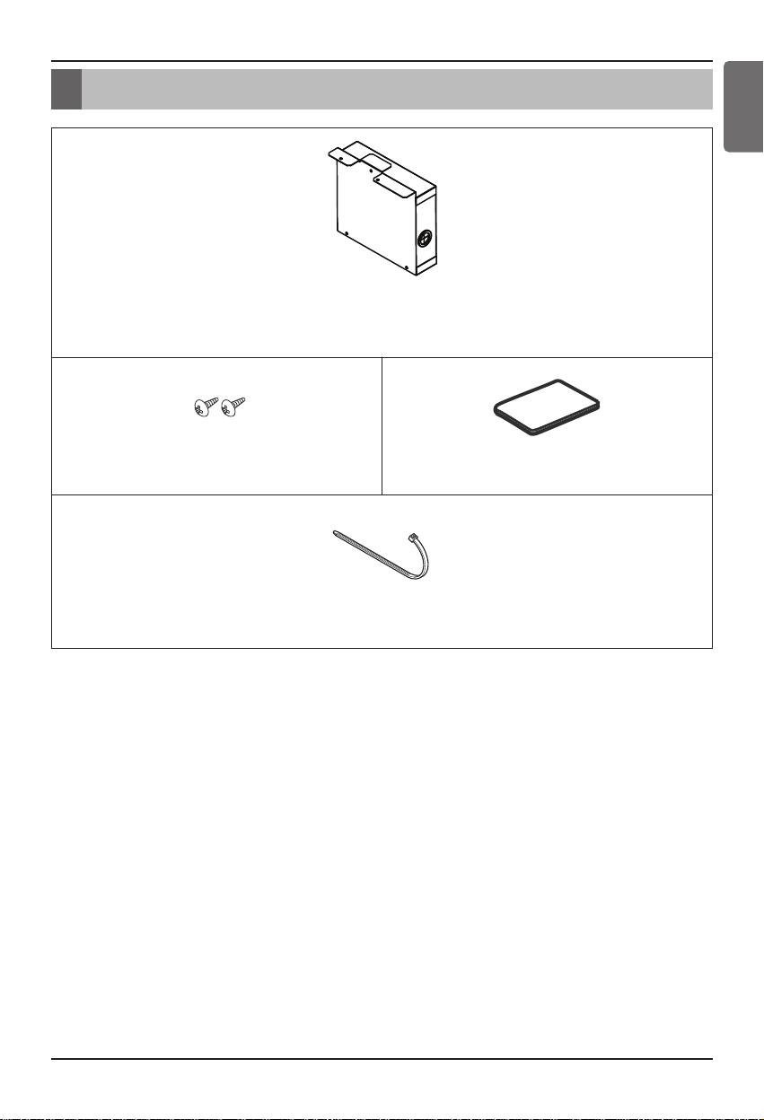
Accessory Parts
Controller Assy
(Variable Water Flow Control Board,
Transformer, Terminal Block, Harness Single)
Screw(2EA)
Manual
Tie (1EA)
Name of each Part
6 Variable Water Flow Controller Kit
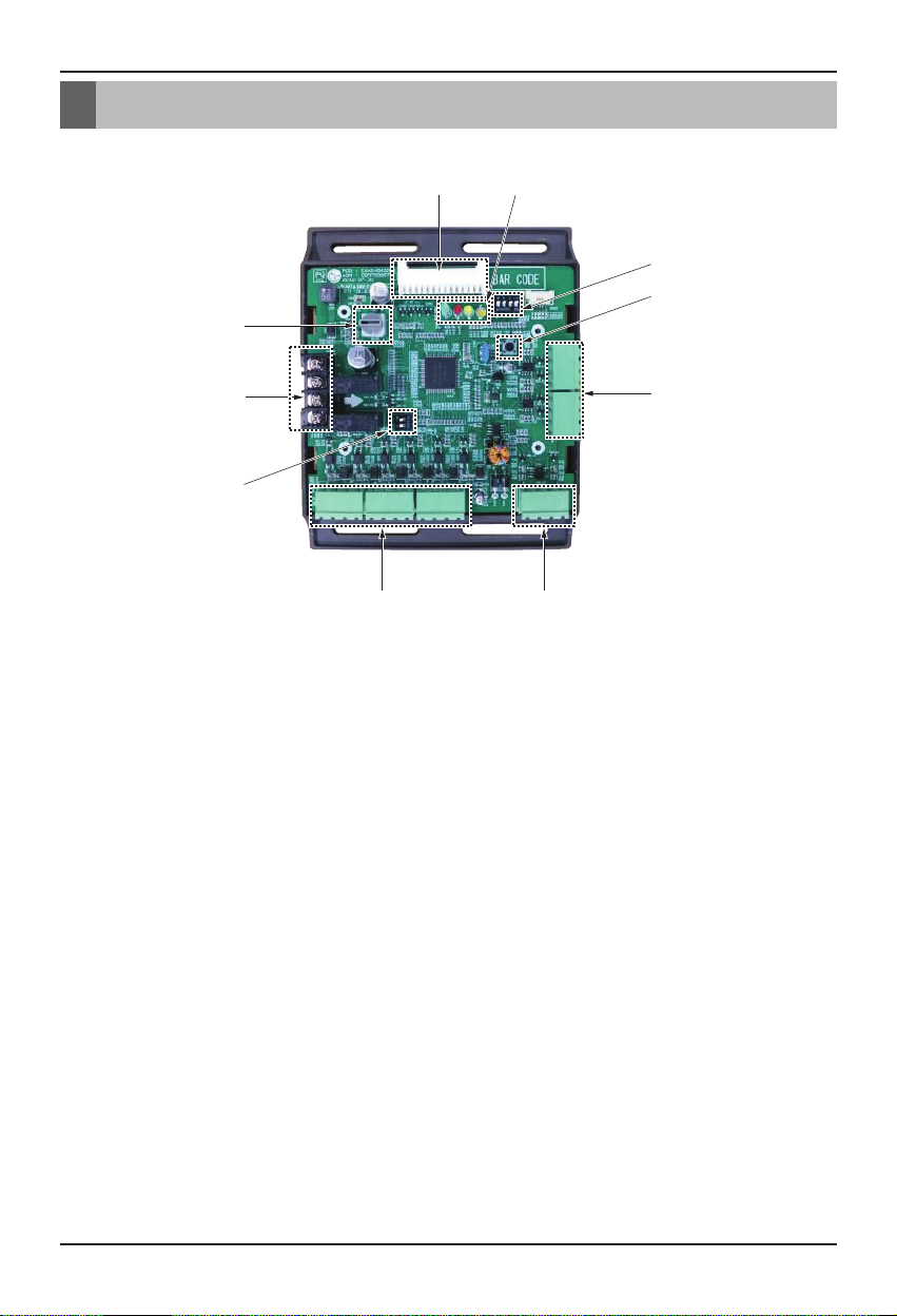
Name of each Part
① Main connector : Power input and communication connector with Outside Unit
② SW104 : Rotary Switch for setting capacity control step
③ Digital Output : Operating & Error status Relay output (DDC output AC 1A at 250V source)
④ SW102 : Switch for setting internal function
⑤ Digital Input : Dry contact input
⑥ Analog Input : DC 0~10V Analog signal input
⑦ Analog Output : DC 0~10V Analog signal output
⑧ SW103 : Reset Switch
⑨ SW101 : DIP Switch for setting operating function
⑩ LED : Indicate VWFC*(board) status
- LED1C(Green) : communication status (receive)
- LED2C(Red) : communication status (transfer)
- LED3C(Yellow) : Communication error status
- LED4C(Orange) : Power status
* Variable Water Flow Control Kit
ڹ
ڸہ
ۀ
ڿ
ں
ڻ
ڼڽ
ھ

Variable Water Flow Control kit – Functions summary
Installation manual 7
ENGLISH
Variable Water Flow Control kit – Functions summary
Variable Water Flow Control
This function can be applied to save pump operation power by optimizing water flow rate by
interlocking between electric valve and MULTI V WATER IV operation. Depends on MULTI V
WATER IV operation cycle, Variable Water Flow Control Kit(Board) outputs analog signal
(0~10V) to electric valve.
CAUTION
Please keep water flow rate more than 40% of rated water flow indicated MULTI V WATER
IV PDB
Demand control
- This function is to reduce Outside Unit power consumption by using input signal. This manual
provides variable setting to control outside unit capacity according to input method. This function
supports 2 types of input signal : AI(0~10V) and contact signal(3 Step).
Output Outside or Indoor Unit Operation status
- This function displays outside or indoor unit’s operation status. Depends on DIP switch setting,
either outside or indoor unit operation status is reflected through output signal.
Output Outside or Indoor Unit Error Status Signal
- This function displays error signal by digital output when either outside or indoor unit has an
error

Installation Method
8 Variable Water Flow Controller Kit
Variable Water Flow Control kit Installation Method
Installation Method
① Be sure to turn off outside unit power before installaion.
② Separate front panel from outside unit
③ Separate front cover of control box.
④ Separate Oil_Level Harness(3Pin Yellow) in External PCB(CN28).
⑤ Sepatate VWFC* Cover in VWFC Assy.
⑥ Install the VWFC Assy to the C/Box by using screws.
* VWFC : Variable Water Flow Control kit
ڹ
ں
* Separate of Oil_Level harness
* Tighten the screw from bottom to
the top direction.
ڻ
ڽ
ڼ
CAUTION
Be sure to turn off outside unit power before installation.
Installation Method
Installation manual 9
ENGLISH
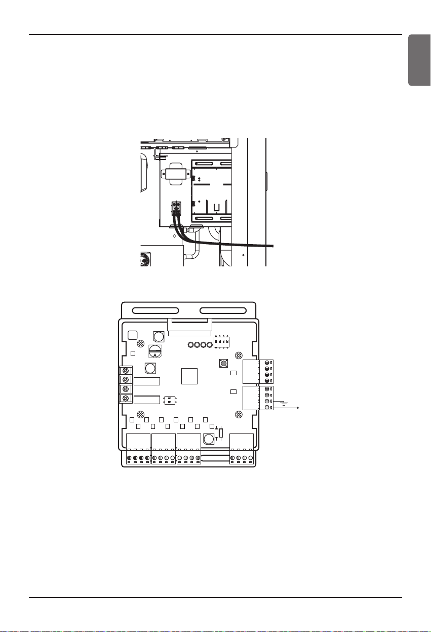
⑦ Connect a power cable (AC 24V) of water flow control valve to the terminal block
(2Pin Terminal block, Max current 0.42A).
⑧ Connect a signal cable (DC 0~10V) of water flow control valve to CN1_A0(A0_1(A+), GND(A-))
of VWFC.
⑨ Set up the main function DIP Switch of VWFC PCB. (Refer to 16page)
⑩ Pull out put through the cover hole.
⑪ Install the VWFC Cover by using screws.
ھ
AO_1
ڿ

Setting and Using Method
10 Variable Water Flow Controller Kit
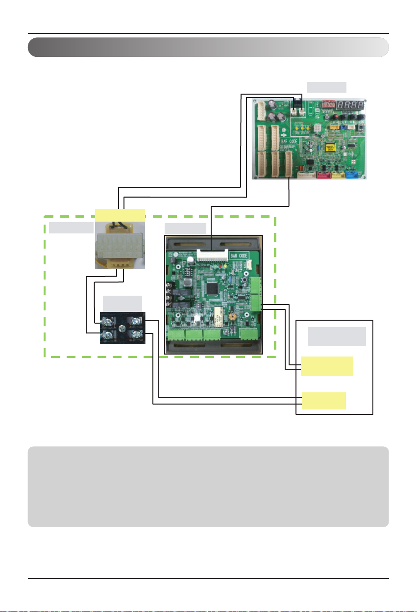
⑫ Connect the blue cable of transformer to the Main PCB(CN_JIG_N,CN_JIG_L).
⑬ Connect the black cable of VWFC PCB to the Main PCB(CN10).
⑭ Connect the Oil_Level harness(3Pin Yellow) to the External PCB(CN28).
⑮ Fix and fasten components and cables.
⑯Turn on the main power line of outside unit.
1. Install the product on flat surface and screw at least 2 places. Otherwise the VWFC PCB may not be
anchored properly.
2. Do not deform the case at random. It may cause malfunction of the Variable Water Flow Control PCB
3. This is a class A product. In a non-industrial environment, this product may cause radio interference, in
which case the user may be required to take adequate measures.
4.
It must be installed variable flow valve on water circulation system in advance.
5. The internal resistance of variable water flow control valve must be above 100kΩ. The resistance of
signal cable(CN1_A0) must be below 10Ω.
ۃ
ۄ

Setting and Using Method
Installation manual 11
ENGLISH
1. Wiring Diagram
Setting and Using Method
Setting and Using Method
12 Variable Water Flow Controller Kit
AO_1
2. Wiring for Variable Water Flow Control kit
Notes
Transformer can supply only AC 24V to the terminal block
Do not input external power into Main PCB. Otherwise it will cause a serious damage.
The Variable Water Flow Control Kit controls only 1 valve actuator.
The power (AC 24V) and signal(DC 0~10V) line is recommended by AWG22(1/32 in, (0.644 mm),
0.016 Ω/ft (0.053 Ω/m)).
Please refer to the variable water flow control valve installation manual for wiring.
1 Unit
h BL : Blue, RD : Red, BK : Black
BL
Transformer
BL
AC 220-240V
VWFC Board
BK
Main PCB
RD
RD
Terminal
Block
AO_1
AO_1
Variable Water
Flow Valve
DC 0~10V
Control Signal
AC 24V
Setting and Using Method
Installation manual 13
ENGLISH
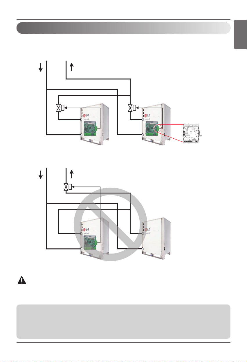
3. Series Installation(more than 2 unit)
For Variable Water Flow Control
Please apply an individual PWFCKN000 model for each MULTI V WATER IV unit
CAUTION
Variable Water Flow Control Kit only can control 1 unit of MULTI V WATER IV and electric
valve.
Notes
Communication line from controller such as DDC must be installed only with VWFC of master outside unit.
- Demand control
- Output outside or indoor unit operation status
- Output outside or indoor unit error status signal
Water
Inlet
Water
Inlet
Water
Outlet
Water
Outlet
Master Slave
AO_1
Master Slave
Setting and Using Method
14 Variable Water Flow Controller Kit
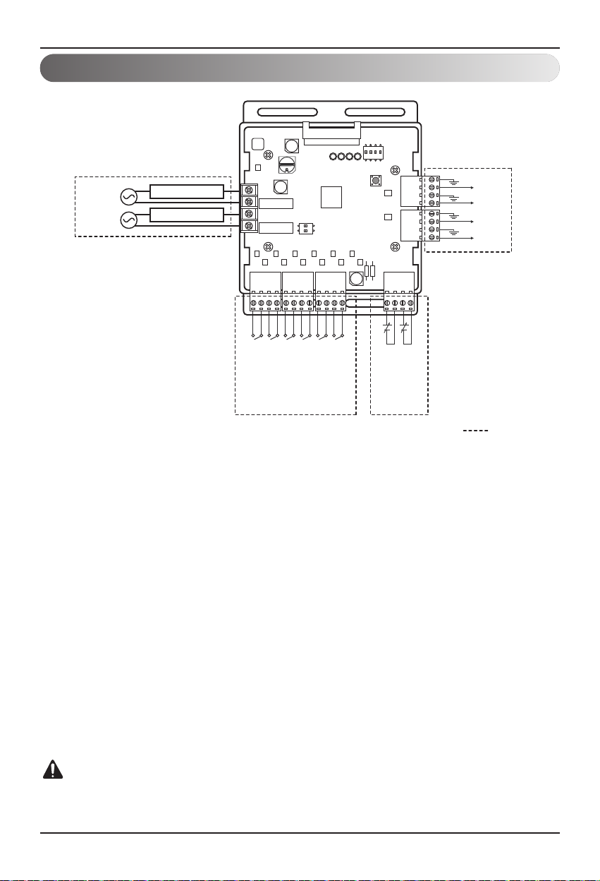
4. Power source input
① Dry contact input part
• Input_1,2,3 : Demand control by contact input(3 Step)
• Input_LNO : Low Noise Operation
• Priority setting
Using ‘Priority setting’ contact signal the priority of command.
(Demand control for external command from DDC vs peak control by LG Centrol controller.)
- Close : Central controller has priority to external signal
- Open : External signal has priority to central controller(default setting)
② Analog input part (AI : DC 0 ~ 10V)
• AI_1 : Demand control by analog input (10 Step)
③ Analog output part(AO : DC 0 – 10V, Max 20 mA)
• AO_1 : Connect analog output signal for variable water flow valve.
④ Digital Output (DDC output AC 1A at 250V source)
• Output error status
• Output operation status
CAUTION
Power must be turned on after the product is wired completely.
AO_4
AO_3
AO_2
AO_1
Field Wiring
ڻ
Power
AC or DC
Power
AC or DC
Error Status
Operating Status
Input_1
Input_2
Input_3
Input_LNO
Reserved
ڸ
Priority setting
AI_1
Reserved
ڹ
ں

Setting and Using Method
Installation manual 15
ENGLISH
n
Communication and Power Line
- If communication and power lines are run alongside each other then there is a strong likelihood of
operational faults developing due to interference in the signal wiring caused by electrostatic and
electromagnetic coupling. The tables below indicates our recommendation as to appropriate spacing
of communication and power lines where these are to be run side by side.
Current capacity of power line Spacing
100V or more
10A 11-13/16 in (300 mm)
50A 19-11/16 in (500 mm)
100A 39-3/8 in (1,000 mm)
Exceed 100A 59-3/64 in (1,500 mm)
Notes
If the power supply waveform continues to exhibit some distortion the recommended spacing in the
table should be increased.
• If the lines are laid inside conduits then the following point must also be taken into account when
grouping various lines together for introduction into the conduits.
• Power lines (including power supply to air conditioner) and signal lines must not be laid inside the
same.
• In the same way, when grouping the lines power and signal lines should not be bunched together.

Setting and Using Method
16 Variable Water Flow Controller Kit
CAUTION
After change ‘DIP Switch’ setting, then you must press reset switch to reflect the setting.
Before operating the outside unit, check the flow rate of water and voltage signal of PCB.
Minimum flow rate of water is recommended 40% of rated flow rate. Otherwise, the outside unit
get damage.
Position Function
Control signal : DC 0V(OFF), DC 8~10V(ON)
Control signal : DC 0V(OFF), DC 6~10V(ON)
Control signal : DC 0V(OFF), DC 4~10V(ON)
Default status
Control signal : DC 0V(OFF), DC 2~10V(ON)
ON
L1 2 3 4
ON
L1 2 3 4
ON
L1 2 3 4
ON
L1 2 3 4
• Output signal setting : SW101 L1, L2
5. Variable Water Flow Control Kit Functions
Setting of DIP Switch
Using 'SW101', select the minimum analog output value as described below to meet the
requirement of applied valve or to keep minimum flow rate.
L1
ON
2
3
4
Notes
Default status is all off.
SW101

Setting and Using Method
Installation manual 17
ENGLISH
Position Function Wiring
ON
L1 2 3 4
ON : Activate Digital Output according to Indoor Unit status
OFF : Activate Digital Output according to Outside Unit status
Operation
status
Using ‘SW101’, Select the option of control function as described below.
- Operation Status output
• Operation status output : SW101 L4
Depends on SW101 L4 position(ON/OFF), VWCK(Board) is operated as below
L1
ON
2
3
4
Notes
Default status is all off.
SW101
Dip Switch VWCK(Board) operation
SW101 L4 ON
When even one of indoor unit (Remote controller) is turned on → Relay on
All Indoor are turned off → Relay off
SW101 L4 OFF
When even one of compressor is turned on → Relay on
All compressor are turned off → Relay off
CAUTION
After change DIP SW setting, press reset switch to reflect the setting.

Setting and Using Method
18 Variable Water Flow Controller Kit
L1
ON
2
Notes
Default status is all off.
CAUTION
Do not operate the DIP SW except authorized person.
After change DIP SW setting, press reset switch to reflect the setting.
Position Function
ON
L1 2
ON : Ignore minimum Analog output value setting
(L1,L2 setting value of 4pin DIP SW)
OFF : Follow minimum Analog output value setting
(L1,L2 setting value of 4pin DIP SW)
• Set Analog output Range : SW102 L2
Basically this module keeps a minimum Analog output voltage refer to L1,L2 setting of SW101 to
prevent unexpected accident. When you need to use 0~10V full range, L2 should be set as ON.
When communication error happened, LED3C(yellow) will truned ON
The setting method makes to open the valve using output signal when occur communication error.
• Set analog output default value in case that communication error between VWFC and outside
unit PCB is occurred : SW102 L1
Using ‘SW102’, Select the option of control function as described below.
- Set analog output optional function
SW102
Position Function Wiring
ON
L1 2
ON : Analog output 0V
OFF : Analog output 10V
AO_1 ~ 4

Setting and Using Method
Installation manual 19
ENGLISH
Setting For Demand control
Use the Rotary Switch to set a control step for contact signal input : The type of input signal and
control step can be set using ‘SW104’
This function is for Demand control to reduce power consumption.
Set the control mode what you want according to the table as below.
CAUTION
Do not change a command too quickly.
Keep the command 30 seconds at least, otherwise it will cause a damage to outside unit.
• Operation rate condition :
- Cooling : Outside 35 °C, Indoor 27 °C
- Heating : Outside 7 °C, Indoor 20 °C
• The tolerance of the operation rate can be cause by combination of outside unit, operating
condition, installation circumstance.
• When operation rate is 100%, Target Evaporating Temp. and Target Condensing Temp. can be
changed by installation option.
• Input_1 : 0 OFF, Input_1 : 1 ON
- Setting of Demand control by type of input signal
Input signal
SW_STEP
Wiring
Demand control by contact input 0, 1, 2, 3, 4, 5, 6, 7 Input 1,2,3
Demand control by analog input(0~10V) C, D, E AI_1
Setting and Using Method
20 Variable Water Flow Controller Kit
• Demand control by contact input control (3 Step)
3
0 0 0 No control -
No control -
Contact
signal
1 0 0 5.9 70% 40.4 70%
0
1 0 11.0 40% 31.3 40%
00
1 All off 0% All off 0%
4
0 0 0 No control -
No control -
1 0 0 5.9 70% 40.4 70%
0
1 0 9.0 50% 34.5 50%
00
1 All off 0% All off 0%
5
0 0 0 No control - No control -
1 0 0 5.0 80% 43.1 80%
0 1 0 9.0 50% 34.5 50%
0 0 1 All off 0% All off 0%
6
0 0 0 No control - No control -
1 0 0 9.0 50% 34.5 50%
0 1 0 Comp off 0% Comp off 0%
0 0 1 All off 0% All off 0%
7
0 0 0 No control - No control -
1 0 0 5.5 75% 41.8 75%
0 1 0 9.0 50% 34.5 50%
0 0 1 All off 0% All off 0%
SW_ STEP Input_1 Input_2 Input_3
Cooling Heating
Type of
input
Evaporating
Temp. [°C]
Operation
rate
Condensing
Temp. [°C]
Operation
rate
0
0 0 0 No control -
No control -
Contact
signal
1 0 0 5.9 70% 40.4 70%
0
1 0 11.0 40% 31.3 40%
00
1 Comp off 0% Comp off 0%
1
0 0 0 No control -
No control -
1 0 0 5.9 70% 40.4 70%
0
1 0 9.0 50% 34.5 50%
00
1 Comp off 0% Comp off 0%
2
0 0 0 No control - No control -
1 0 0 5.0 80% 43.1 80%
0 1 0 9.0 50% 34.5 50%
0 0 1 Comp off 0% Comp off 0%
Setting and Using Method
Installation manual 21
ENGLISH
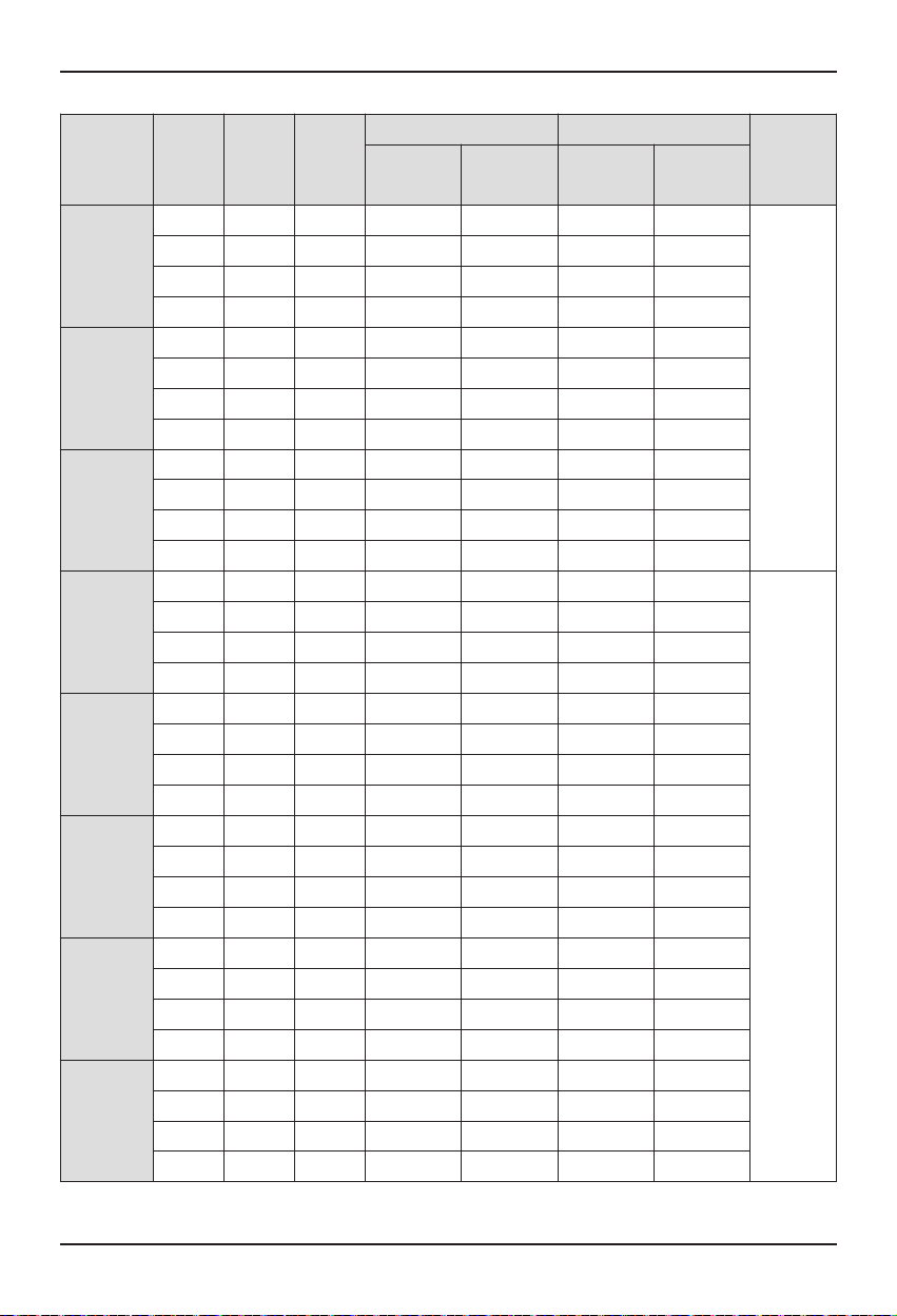
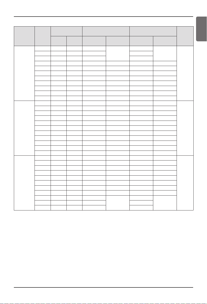
• Demand control by analog input control (10 Step)
SW_ STEP
Normal
(V)
Input voltage
range(V)
Cooling Heating
Type of
input
Min Max
Evaporating
Temp. [°C]
Operation
rate
Condensing
Temp. [°C]
Operation
rate
C
0 0 0.4 Comp off
0%
Comp off
0%
Analog
input
1 0.6 1.4 Comp off Comp off
2 1.6 2.4 Comp off Comp off
3 2.6 3.4 11.0 40% 31.3 40%
4 3.6 4.4 9.8 45% 33.3 45%
5 4.6 5.4 9.0 50% 34.5 50%
6 5.6 6.4 7.2 60% 37.5 60%
7 6.6 7.4 5.9 70% 40.4 70%
8 7.6 8.4 5.0 80% 43.1 80%
9 8.6 9.4 4.1 90% 45.6 90%
10 9.6 10 3.1 100% 48.1 100%
D
0 0 0.4 No control - No control -
Analog
input
1 0.6 1.4 3.1 100% 48.1 100%
2 1.6 2.4 4.1 90% 45.6 90%
3 2.6 3.4 5.0 80% 43.1 80%
4 3.6 4.4 5.9 70% 40.4 70%
5 4.6 5.4 7.2 60% 37.5 60%
6 5.6 6.4 9.0 50% 34.5 50%
7 6.6 7.4 9.8 45% 33.3 45%
8 7.6 8.4 11.0 40% 31.3 40%
9 8.6 9.4 Comp off 0% Comp off 0%
10 9.6 10 All off 0% All off 0%
E
0 0 0.4 Comp off 0% Comp off 0%
Analog
input
1 0.6 1.4 11.0 40% 31.3 40%
2 1.6 2.4 9.8 45% 33.3 45%
3 2.6 3.4 9.0 50% 34.5 50%
4 3.6 4.4 7.2 60% 37.5 60%
5 4.6 5.4 5.9 70% 40.4 70%
6 5.6 6.4 5.0 80% 43.1 80%
7 6.6 7.4 4.1 90% 45.6 90%
8 7.6 8.4 3.1
100%
48.1
100%9 8.6 9.4 3.1 48.1
10 9.6 10 3.1 48.1

Setting and Using Method
22 Variable Water Flow Controller Kit
6. Setting of Outside Unit DIP Switch
Variable Water flow Control Kit Mode
• Steps for setting of Variable water flow control mode
Set the switch No.5 of outside unit ON
Select the “Func” mode using ‘▶’ and ‘◀’
button, and then press the confirm button '●'
Select the “Fn4” using ‘▶’ and ‘◀’ button,
and then press the confirm button '●'
Press reset button to reflect the setting
Setting of variable water flow control kit is
finished
h If you want to stop the variable water flow control mode, follow the same step and make “Fn4” “Off”
Select the “On” using ‘▶’ and ‘◀’ button,
and then press the confirm button '●'
CAUTION
After change ‘DIP Switch’ setting, then you must press reset switch to reflect the setting.
Before operating the outside unit, check the flow rate of water and voltage signal of PCB.
Minimum flow rate of water is recommended 40% of rated flow rate. Otherwise, the outside unit
get damage.
DIP SWITCH 7-Segment
SW04C
( X : cancel)
SW03C (
SW02C ( : backward)
SW01C ( : confirm)
SW01D (reset)
: forward)
ȯ
ȭ
Ɨ

Setting and Using Method
Installation manual 23
ENGLISH
7. Setting Example
Using
Demand control
Using Demand control function with 3-Non Voltage contact.
LG does not supply this section
(Field supply)
With this function comp capacity of outside unit can be controlled.
Ex) Demand control by 3-contact signal
SW_ STEP Input_1 Input_2 Input_3
Comp capacity Of outside
unit(%)
Type of input
0
0 0 0 No control
Contact signal
100 70
0
10 40
00
1 Comp off
CAUTION
• This input can accept only non voltage contact.
Do not input external power source. Otherwise it will cause a serious damage.
Input_1
Input_2
Input_3
Input_LNO
Reserved
Reserved

Setting and Using Method
24 Variable Water Flow Controller Kit
With this function compressor capacity of outside unit can be controlled by Building Management
System.
Ex) Demand control by Analog input signal Refer to Detail of the control step for analog input
signal.
CAUTION
• This function is sensitive to voltage level.
So when using analog input, make a signal cable as short as possible.
• Do not change a command too quickly.
Keep the command 30 seconds at least, otherwise it will cause a damage to outside unit.
Using Demand control function with 0~10V DC voltage signal
LG does not supply this section
(Field supply)
DC 0~10V
input
Direct Digital
Controller
GND

Setting and Using Method
Installation manual 25
ENGLISH
CAUTION
When using high voltage over than AC24V, make sure to use H07RNF wire.
① Error Display
: This function displays error signal by digital output when either outside or indoor unit has an
error
② Operating Display
: This function is depend on 4th DIP SW setting of ‘SW101’.
- L4 is ON : Display indoor unit operating status (Include FAN mode only)
- L4 is OFF : Display outside unit operating status (Compressor operating on/off status)
Operation Status
LG does not supply this
section (Field supply)
Status output Relay can
endure 250VAC, 1A.
Position Function
ON
L1 2 3 4
ON : Activate Digital Output according to indoor unit status
OFF : Activate Digital Output according to outside unit status
• L4 : Set Operating status output
Power
AC or DC
Power
AC or DC
Error Status
Operating Status

26 Variable Water Flow Controller Kit

 Loading...