

LG PUDCA0 INSTALLATION MANUAL

개정일자 :
QA 요청사항 :
예
바코드와 P/No.가 일치하는가? (바코드 확인)
예
언어표시띠의 위치(누락여부)는 바른가?
예
약물(기호)이 깨지거나 위치가 어긋 난 곳은 없는가?
예
그림이 가려지거나 잘려나간 곳은 없는가?
KUKJE-127
문서번호
CWROM-1606-00197
Order No.
MFL50024811
P/No.
최종 컨펌일자 :
작업자
연구실 담당자
희령
김동겸
예
작업원고와 수정내용이 일치하는가?
* 필수확인 - QA요구사항
*최종 확인후 본 체크리스트는 삭제됩니다.
1. 원고에 지시된 대로 작업한 후 이상없이 작업 되었는지 재차 검토 후 PDF 파일을 생성한다.
2. 작업완료 후 담당 연구원에게 수정부분에 대한 검증요청한다.
(*** 반드시 필요 – 의뢰자가 요청한 의도대로 작업이 정확히 되었는지 반드시 확인이
필요함)
3. 아래 체크리스트에 따라 놓치기 쉬운 사항을 우선으로 한번 더 확인한다.
2016-6-1

INSTALLATION MANUAL
AHU
COMMUNICATION KIT
ENGLISH
Please read this installation manual completely before installing the product.
Installation work must be performed in accordance with the national wiring
standards by authorized personnel only.
Please retain this installation manual for future reference after reading it
thoroughly.
PUDCA0
www.lg.com
P/NO : MFL50024811

TIPS FOR SAVING ENERGY
2
ENGLISH
TIPS FOR SAVING ENERGY
Here are some tips that will help you minimize the power consumption when you use the air
conditioner. You can use your equipment more efficiently by referring to the instructions
below:
• Do not cool excessively indoors. This may be harmful for your health and may consume more
electricity.
• Block sunlight with blinds or curtains while you are operating the equipment.
• Keep doors or windows closed tightly while you are operating the equipment.
• Adjust the direction of the air flow vertically or horizontally to circulate indoor air.
• Speed up the fan to cool or warm indoor air quickly, in a short period of time.
For your records
Staple your receipt to this page in case you need it to prove the date of purchase or for warranty
purposes. Write the model number and the serial number here:
Model number :
Serial number :
You can find them on a label on the side of each unit.
Dealer’s name :
Date of purchase :

IMPORTANT SAFETY INSTRUCTIONS
IMPORTANT SAFETY INSTRUCTIONS
READ ALL INSTRUCTIONS BEFORE USING THE APPLIANCE.
Always comply with the following precautions to avoid dangerous situations and ensure peak
performance of your product
WARNING
!
It can result in serious injury or death when the directions are ignored
CAUTION
!
It can result in minor injury or product damage when the directions are ignored
WARNING
!
• Installation or repairs made by unqualified persons can result in hazards to you and others.
• Installation MUST conform with local building codes or, in the absence of local codes, with
the Nation Electrical Code NFPA 70/ANSI C1-1003 or current edition and Canadian Electrical
Code Part1 CSA C.22.1.
• The information contained in the manual is intended for use by a qualified service technician
familiar with safety procedures and equipped with the proper tools and test instruments.
• Failure to carefully read and follow all instructions in this manual can result in equipment malfunction, property damage, personal injury and/or death.
Installation
• Always perform grounding.
- Otherwise, it may cause electrical shock.
• Don’t use a power cord, a plug or a loose socket that is damaged.
- Otherwise, it may cause fire or electrical shock.
• For installation of the product, always contact the service center or a professional installation
agency.
- Otherwise, it may cause fire, electrical shock, explosion or injury.
• Securely attach the electrical part cover to AHU Comm. Kit.
- If the electric part cover of AHU Comm. Kit is not attached securely, it could result in a fire or
electric shock due to dust, water, etc.
• Always install an air leakage breaker and a dedicated switching board.
- No installation may cause a fire and electrical shock.
• Do not keep or use flammable gases or combustibles near the equipment.
- Otherwise, it may cause a fire or the failure of product.
• Do not install, remove or reinstall the unit by yourself.
- Otherwise, it may cause a fire, electrical shock, explosion or injury.
• Do not disassemble or repair the product randomly.
- It will cause a fire or electrical shock.
• Do not install the product in a place where there is the concern of falling down.
- Otherwise, it may result in personal injury.
• Use caution when unpacking and installing.
- Sharp edges may cause injury.
3
ENGLISH

ENGLISH
IMPORTANT SAFETY INSTRUCTIONS
4
Operation
• Do not share the outlet with other appliances.
- It will cause an electric shock or a fire due to heat generation.
• Do not use the damaged power cord.
- Otherwise, it may cause a fire or electrical shock.
• Do not modify or extend the power cord randomly.
- Otherwise, it may cause a fire or electrical shock.
• Take care so that the power cord may not be pulled during operation.
- Otherwise, it may cause a fire or electrical shock.
• Unplug the unit if strange sounds, smell, or smoke comes from it.
- Otherwise, it may cause electrical shock or a fire.
• Keep flames away.
- Otherwise, may occur a fire.
• Take the power plug out if necessary, holding the head of the plug and do not touch it with
wet hands.
- Otherwise, it may cause a fire or electrical shock.
• Do not use the power cord near the heating tools.
- Otherwise, it may cause a fire and electrical shock.
• Do not allow water to run into electrical parts.
- Otherwise, it may cause the failure of machine or electrical shock.
• Hold the plug by the head when taking it out.
- It may cause electric shock and damage.
• Be cautious that water could not enter the product.
- Otherwise, it may cause a fire electrical shock or product damage.
• Do not step on the indoor/outdoor unit and do not put anything on it.
- It may cause an injury through dropping of the unit or falling down.
• Do not place a heavy object on the power cord.
- Otherwise, it may cause a fire or electrical shock.
• When the product is submerged into water, always contact the service center.
- Otherwise, it may cause a fire or electrical shock.

TABLE OF CONTENTS
TABLE OF CONTENTS
5
ENGLISH
2 TIPS FOR SAVING
ENERGY
3 IMPORTANT SAFETY
INSTRUCTIONS
6 INSTALLATION SCENE
7 SUPPLIES
8 ACCESSORIES
9 PART DESCRIPTION
9 Communication Kit (PUDCA0)
10 BEFORE INSTALLATION
24 AHU KIT WIRING CON-
FIGURATION WITH DDC
24 Configuration concept
25 DI Wring concept
26 DO Wring concept
27 AI Wring concept
29 PI 485 connection_essential accessory
30 FAN Signal Wiring Concept
31 THERMISTORS INSTAL-
LATION
31 Pipe thermistors Installation
34 TROUBLESHOOTING
13 COMMUNICATION KIT
INSTALLATION
13 Mechanical installation
14 Electric Wiring Work
16 Electrical Work
17 Electric Wiring Work
18 Controller Setting Method

INSTALLATION SCENE
Signal
Pipe
Thermistor
4
11
6
8
9
7
2
10
5
1
Field supply
DDC
A
i
r
fl
o
w
3
6
ENGLISH
INSTALLATION SCENE
* Applicable ODU model
Type Model Available
Standard
CAUTION
!
• Before installation of outdoor unit, check the serial Number, 1st digit indicates year, and 2nd/3rd
digits mean month of production. For example, 503KCSFONT26 was produced on March 2015.
UU18W.UE4
UU30W.U44
UU70W.U34
UU85W.U74
AllUU24W.U44
Produced from May.2015
Parts and components
No. Name Remarks
1 AHU Field supply
2 Outdoor Unit Single CAC
3 AHU Communication Kit(PUDCA0) 4 DDC Field supply(Central control Device)
5 Field piping Field supply
Wiring connections
6 Communication Kit Wiring
7 Pipe thermistors Evaporator (In/Out) control of AHU
Power supply and communication
between comm. kit and outdoor unit
8 Room thermistor Return air control
9
10 PI485 (PMNFP14A0/PMNFP14A1) Essential accessory
11 Signal
CAUTION
!
• For installation of Room thermistor (No. 8), always place it at the inlet of Heat Exchanger.
Remote controller
(PQRCVSL0/ PQRCVSL0QW)
Optional accessory
• Fan signal(Low / Middle / High)
• Defrost / Heating / Cooling signal
• Themal On/Off
Otherwise, it might not operate properly.

W
D
H
SUPPLIES
PUDCA0
Compo-
AHU Comm.
nents
P/NO
Kit
AJT74975201 EBG61106821
Shape
Room
thermistor
Pipe
thermistors
EBG61287703(In)
EBG61287704(Out)
Installation
Manual
Bracket Option PCB
MFL50024811 MAZ49398901
SUPPLIES
EBR65102902~04
EBR52358920
EBR52358921
7
ENGLISH
Quanti-
ty(EA)
1 1 2(Each 1) 1 4 5(Each 1)
Weight (kg) Dimension (mm)
Model
Name
NET Gross
NET Gross
W H D W H D
PUDCA0 6.32 7.92 330 180 430 420 232 540
POWER
220-240 V~ 50 Hz
220 V~ 60 Hz
208/230 V~ 60 Hz

ACCESSORIES
8
ENGLISH
ACCESSORIES
Components Remote controller PI 485
Model name
Shape
Accessories
PQRCVSL0
PQRCVSL0QW
(Optional accessory) (Essential accessory)
PMNFP14A0
PMNFP14A1
* For further details of the accessories, refer to the manual provided at the time of purchasing
the accessories.
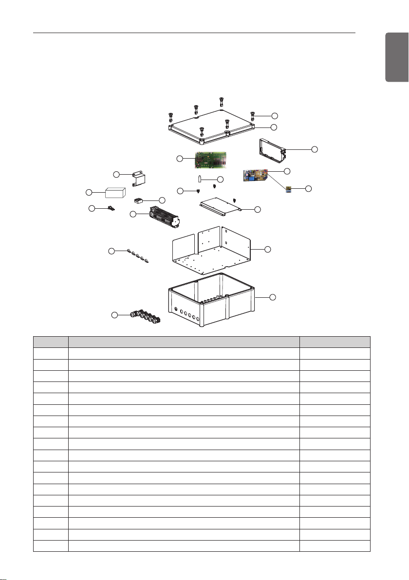
1
2
12
4
5
13
8
3
9
14
17
11
10
16
15
18
7
6
PART DESCRIPTION
Communication Kit (PUDCA0)
PART DESCRIPTION
9
ENGLISH
No. m Part Name Quantity (EA)
1 Plastic (+) Bolt 6
2 Cover 1
3 Expansion I/O PCB 1
4 Supporter (Connect No. 3) 6
5 Main PCB case 1
6 Main PCB 1
7 Option PCB (24 kBtu/hr) 1
8 Bracket (For Adaptor) 1
9 AC/DC Convertor 1
10 Supporter (Fixing Wiring) 7
11 Terminal Block (Communication) 1
12 Terminal Block (POWER Supply) 1
13 Clamp Cord (For Power Wiring) 1
14 Clamp Cord 5
15 Panel 1
16 Control Box Case 1
17 Cable gland 6
18 Bracket (For Expansion I/O PCB) 1

BEFORE INSTALLATION
10
ENGLISH
BEFORE INSTALLATION
CAUTION
!
Don't install or operate the unit in rooms mentioned below.
•
① Where mineral oil, like cutting oil is present.
② Where the air contains high levels of salt such as air near the ocean.
③ Where sulphurous gas is present such as that in areas of hot spring.
④ In vehicles or vessels.
⑤ Where voltage fluctuates a lot such as that in factories.
⑥ Where high concentration of vapor spray are present.
⑦ Where machines generating electromagnetic waves are present.
⑧ Where acidic or alkaline vapor is present.
⑨ The option boxes must be installed with entrances downward.
Check the mentioned below, when you apply the AHU (Field supply).
•
① If the AHU (Field supply) provided in the field is exclusively for heating, you must not
change the operating mode to cooling on the remote controller. If not, it can cause
electric shock, injury or death. If you want to operate in cooling mode, AHU (Field supply) must comply with the following details.
(Following)
- The insulation level of AHU (Field supply) motor must be ‘F’ or above, and the protection level must satisfy ‘IP 54’.
- AHU (Field supply) must have the drain pan installed.
② Fan speed button on the wired remote controller (PQRCUSA0/1) is not operated.
③ For refrigerant piping of outdoor unit, refer to the installation manual supplied with the
outdoor unit.
④ For installation of the wired remote controller (PQRCUSA0/1), refer to the manual sup-
plied with the wired remote controller.
⑤ For protecting the refrigerant cycle in heating, the inlet Air temperature to the Heat
Exchanger has to be over 5°C.
⑥ The EEV or TXV kit has to be installed on the AHU as close as possible to the Heat
Exchanger.
AHU Communication Kit
•
① Thermistor cable and remote controller wire should be located at least 50 mm away
from power supply wires and from wires to the controller. Not following this guideline
may result in malfunction due to electrical noise.
② Use only specified wires, and tightly connect wires to the terminals. Keep wiring in
neat order so that it does not obstruct other equipment. Incomplete connections could
result in overheating, and in worse case electric shock or fire.

BEFORE INSTALLATION
Capacity setting
'Option PCB'
Detail
CAUTION
!
Selection of Evaporator(AHU)
See table below for applicable units
Selecting the capacity setting 'Option PCB'(Accessory) according to the capacity mentioned
below.
- The corresponding capacity setting 'Option PCB' needs to be selected depending on the
need capacity.
- After checking the need capacity, remove the 24 k Option PCB equipped in the main PCB,
and set up the Option PCB fitted the need capacity in the main PCB.
11
ENGLISH
Option PCB
P/NO
Capacity
(Btu/h)
Standard heat
exchanger volume
(10-3× m3)
Maximum heat
exchanger capacity
(kW)
Air Flow rate
(CMM)
EBR65102902 18 k 2.4 5.0 13~16.5
EBR65102903 24 k 2.6 7.1 14~18
EBR65102904 30 k 2.9 8.0 20~26.5
EBR52358920 70 k 5.2 20.0 60~70
EBR52358921 85 k 5.9 23.0 64~80
* Evaporator Saturated Temperature(SST) = 6 °C, SH (Superheat) 5K, Air Temperature =
27 °C DBT / 19 °C WBT
* Heat exchanger volume [m
-. Pipe cross-section [m
3
] : Pipe cross-section × Tube length
2
] = π × ID2/4
-. Tube length [m] = Tube length of 1 pipe × Tube step × Tube row
 Loading...