

개정일자 :
QA 요청사항 :
예
바코드와 P/No.가 일치하는가? (바코드 확인)
예
언어표시띠의 위치(누락여부)는 바른가?
예
약물(기호)이 깨지거나 위치가 어긋 난 곳은 없는가?
예
그림이 가려지거나 잘려나간 곳은 없는가?
KUKJE-130
문서번호
CWROM-1606-00193
Order No.
MFL50024802
P/No.
최종 컨펌일자 :
작업자
연구실 담당자
희령
김동겸
예
작업원고와 수정내용이 일치하는가?
* 필수확인 - QA요구사항
*최종 확인후 본 체크리스트는 삭제됩니다.
1. 원고에 지시된 대로 작업한 후 이상없이 작업 되었는지 재차 검토 후 PDF 파일을 생성한다.
2. 작업완료 후 담당 연구원에게 수정부분에 대한 검증요청한다.
(*** 반드시 필요 – 의뢰자가 요청한 의도대로 작업이 정확히 되었는지 반드시 확인이
필요함)
3. 아래 체크리스트에 따라 놓치기 쉬운 사항을 우선으로 한번 더 확인한다.
2016-6-1

INSTALLATION MANUAL
AIR
CONDITIONER
ENGLISH
Please read this installation manual completely before installing the product.
Installation work must be performed in accordance with the national wiring
standards by authorized personnel only.
Please retain this installation manual for future reference after reading it
thoroughly.
Applied(AHU)
Comm.kit
www.lg.com
P/NO : MFL50024802

AHU Control Kit Installation Manual
TABLE OF CONTENTS
n Safety Precautions............................................................3
n Installation Scene..............................................................4
n Supplies.............................................................................5
n Optional Accessories ........................................................5
n Part Description.................................................................6
n Before Installation .............................................................7
n Control Kit Installation........................................................9
Mechanical installation...................................................................................9
Electric wiring work .................................................................................10-12
Dip switch setting .........................................................................................12
Dry contact connection_optional accessory................................................13
n Thermistors Installation....................................................14
Pipe thermistors installation....................................................................14-16
Room thermistor...........................................................................................17
n Test Operation..................................................................18
n Troubleshooting ...............................................................19
2 AHU Control Kit
Safety Precautions
WARNING
WARNING
CAUTION
WARNING
Safety Precautions
To prevent injury to the user or other people and property damage, the following instructions must be followed.
n Incorrect operation due to ignoring instruction will cause harm or damage. The seriousness is
classified by the following indications.
This symbol indicates the possibility of death or serious injury.
This symbol indicates the possibility of injury or damage.
n Meanings of symbols used in this manual are as shown below.
Be sure not to do.
Be sure to follow the instruction.
n
Installation
Don't touch with the
hands while the power is
on
•
There is risk of fire or electric
shock.
Use the correctly rated
breaker or fuse.
• There is risk of fire or electric
shock.
n
Operation
When the product is soaked (flooded or
submerged), contact an Authorized Service
Center.
• There is risk of fire or electric shock.
Use standard
parts(connector).
•
Do not install, remove, or reinstall the unit by yourself
(customer).
• There is risk of fire, electric
Do not disassemble or repair
the product. There is risk of fire
or electric shock.
shock, explosion, or injury.
Be cautious that water could not enter the
product.
• There is risk of fire, electric shock, or product
damage.
For electrical work, contact
the dealer, seller, a qualified
electrician, or an Authorized
Service Center.
•
Do not disassemble or repair
the product. There is risk of fire
or electric shock.
For installation, always
contact the dealer or an
Authorized Service Center.
• There is risk of fire, electric
shock, explosion, or injury.
Installation Manual 3
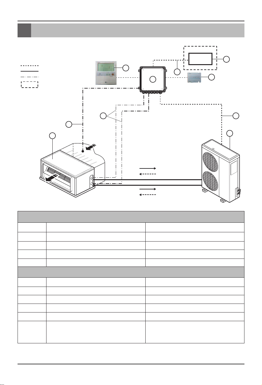
Installation Scene
Signal
Pipe
Thermistor
9
4
10
5
7
8
6
2
3
1
Field supply
DDC
A
i
r
f
l
o
w
Cooling
Heating
Cooling
Heating
Installation Scene
Parts and components
No. Name Remarks
1
2
3
4
Wiring connections
5
6
7
8
9
10
4 AHU Control Kit
Air Handling Unit
Outdoor Unit
AHU Control Kit(PUCKA0)
Control kit wiring
Pipe thermistors
Room thermistor
Remote controller(PQRCUSA0/1)
Dry contact (PQDSBC)
DDC
Signal
Field supply
Universal
Field supply(Central control Device)
(Power supply and communication between control kit and outdoor unit)
Evaporator (In/Out) control of Air Handling Unit
Return air control
Optional accessory
Optional accessory
• Fan signal(Low / Middle / High)
• Defrost / Heating / Cooling signal
• Themal On/Off
-
Supplies
W
D
H
P/NO : MFL50024802
I
NSTALLATION MANUAL
AIR
C
ONDITIONER
www.lg.com
Applied(AHU)
Comm.kit
P
lease read this installation manual completely before installing the product.
Installation work must be performed in accordance with the national wiring
s
tandards by authorized personnel only.
Please retain this installation manual for future reference after reading it
thoroughly.
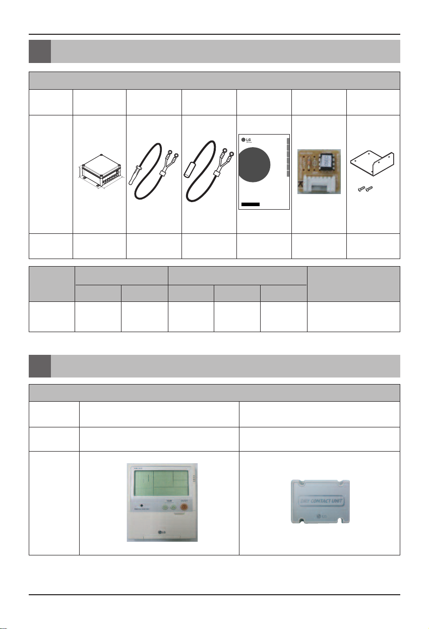
PUCKA0
Components
Shape
Supplies / Optional Accessories
AHU Control Kit Room thermistor Pipe thermistors Installation manual
Capacity setting
option PCB
Panel(Dry contact
support)
Quantity(EA)
112(Pipe In/Out) 1 10(Each 1)
Weight(kg) Dimension(mm)
Model Name
NET Gross WHD
PUCKA0 2.5 4 280 135 280
1Phase, 220~240V,
Optional Accessories
Accessories
Components Remote controller Dry contact
Model name
Shape
PQRCUSA0/1 PQDSBC
1(Panel)
2(Screw)
POWER
50/60Hz
* For further details of the accessories, refer to the manual provided at the time of purchasing the
accessories.
Installation Manual 5
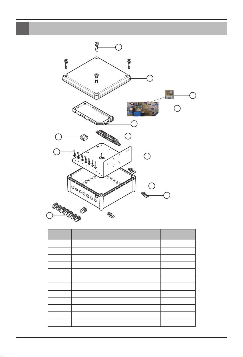
Part Description
1
2
3
4
5
7
11
9
8
10
12
6
CN-OPTION
Part Description
6 AHU Control Kit
No. Part Name Quantity(EA)
1
2
3
4
5
6
7
8
9
10
11
12
Plastic (+) bolt
Control box cover
Terminal block (communication)
Terminal block (POWER Supply)
Main PCB
Option PCB(24k)
Main PCB case
Panel
Support Tie wrap
Control box case
Cable gland(2type)
Bracket
4
1
1
1
1
1
1
1
8
1
8
4

Before Installation
WARNING
CAUTION
Before Installation
n Don't install or operate the unit in rooms mentioned below.
①
Where mineral oil, like cutting oil is present.
②
Where the air contains high levels of salt such as air near the ocean.
③
Where sulphurous gas is present such as that in areas of hot spring.
④
In vehicles or vessels.
⑤
Where voltage fluctuates a lot such as that in factories.
⑥
Where high concentration of vapor spray are present.
⑦
Where machines generating electromagnetic waves are present.
⑧
Where acidic or alkaline vapor is present.
⑨
The option boxes must be installed with entrances downward.
⑩
If you want to install the product outdoors, it should be installed with outdoor casing.
n Check the mentioned below, when you apply the AHU(Field supply).
①
If the AHU (Field supply) provided in the field is exclusively for heating, you must not
change the operating mode to cooling on the remote controller. If not, it can cause electric
shock, injury or death. If you want to operate in cooling mode, AHU (Field supply) must
comply with the following details.
(Following)
- The insulation level of AHU (Field supply) motor must be ‘F’ or above, and the protection
level must satisfy ‘IP 54’.
- AHU (Field supply) must have the drain pan installed.
②
For refrigerant piping of outdoor unit, refer to the installation manual supplied with the
outdoor unit.
③
For installation of the wired remote controller(PQRCUSA0/1), refer to the manual supplied
with the wired remote controller.
④
For connection of the Dry contact (PQDSBC), refer to the manual supplied with the Dry
contact (PQDSBC).
n AHU Control Kit
①
Thermistor cable and remote controller wire should be located at least 50mm away from
power supply wires and from wires to the controller. Not following this guideline may result
in malfunction due to electrical noise.
②
Use only specified wires, and tightly connect wires to the terminals. Keep wiring in neat
order so that it does not obstruct other equipment. Incomplete connections could result in
overheating, and in worse case electric shock or fire.
Installation Manual 7
Before Installation
WARNING
CAUTION
Capacity setting
'Option PCB'
Detail
(Main PCB)
Selection of Evaporator(Air Handling Unit)
See table below for applicable units
Selecting the capacity setting 'Option PCB'(Accessory) according to the capacity mentioned below.
-
The corresponding capacity setting '
capacity.
- After checking the need capacity, remove the 24k
and set up the
Option
(Main PCB)
PCB fitted the need capacity in the main PCB.
Option
PCB' needs to be selected depending on the need
Option
PCB equipped in the main PCB,
Option PCB
P/NO
EBR65102901 12 k 2.2 3.5 9~10
EBR65102902 18 k 2.4 5.0 13~16.5
EBR65102903 24 k 2.6 7.1 14~18
EBR65102904 30 k 2.9 8.0 20~26.5
EBR65102905 36 k 3.1 10.0 26.5~32
EBR65102906 42 k 3.4 12.5 28~36
EBR65102907 48 k 4.0 14.0 30~40
EBR65102908 60 k 4.7 15.0 40~50
EBR52358920 70 k 5.2 20.0 60~70
EBR52358921 85 k 5.9 23.0 64~80
Saturated Suction Temperature (SST) = 6°C, SH (Superheat) = 5K, Air Temperature = 27°C DB / 19°C WB.
Capacity
(Btu/h)
Standard heat
exchanger volume
(103× m3)
Maximum heat
exchanger capacity
(kW)
Air Flow rate
(CMM)
8 AHU Control Kit

Control Kit Installation
298 mm
Provided holes
Ø4.5 mm (4EA)
189 mm
Control Kit Installation
Mechanical installation
1. Remove the Control Kit box cover by unscrewing the plastic (+) bolt(4EA).
2. Drill 4 holes on correct position and fix the Control Kit box securely with 4 screws(Field supply)
through the provided holes Ø4.5 mm(Reference the length of the holes Ø4.5)
Installation Manual 9

Control Kit Installation
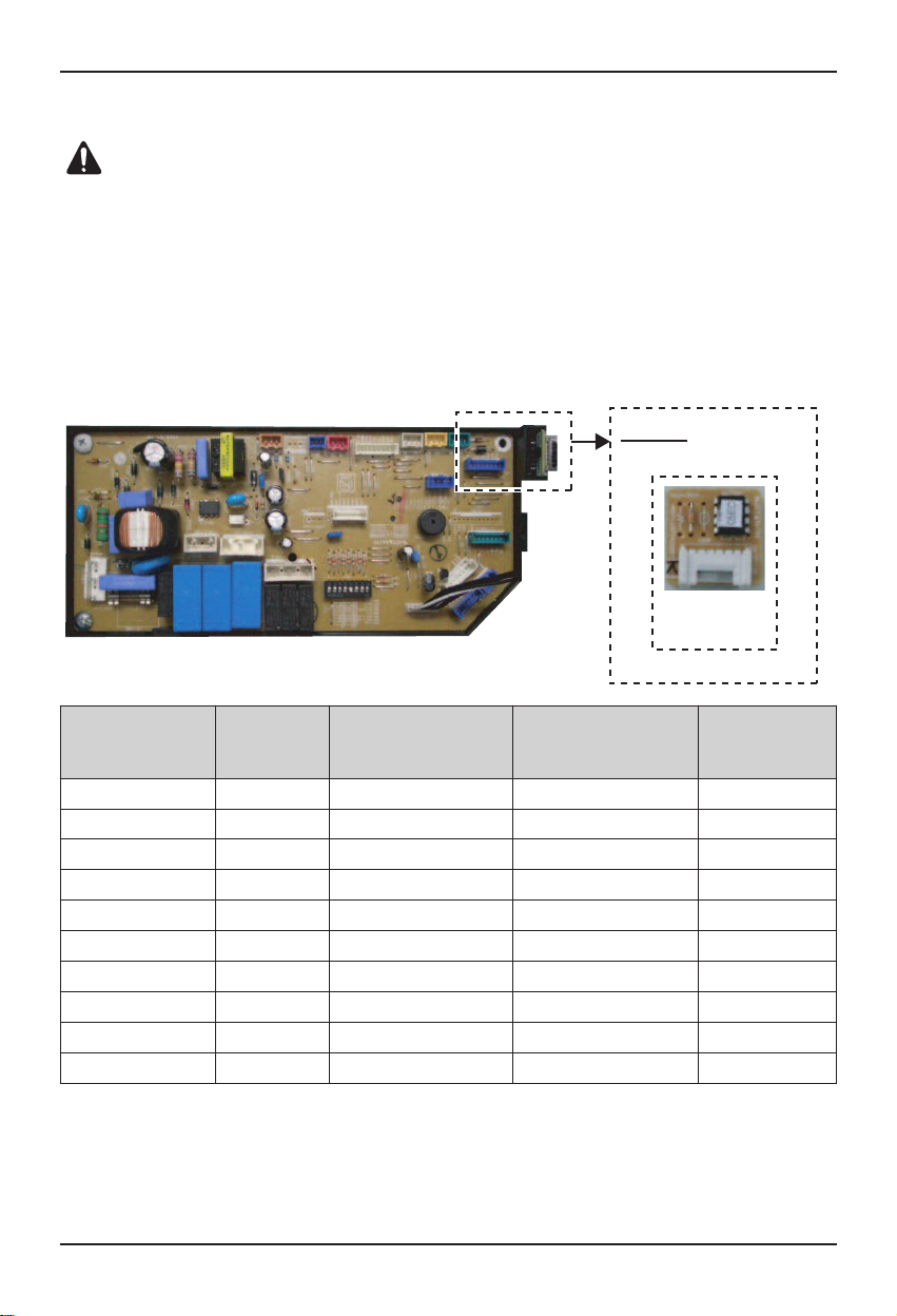
Electric Wiring Work
n
Circuit diagram
1. For electric wiring, refer to figure 'Circuit diagram' mentioned below.
CONNECTOR
NUMBER
CN-POWER AC POWER SUPPLY
CN-D/PUMP FIELD WIRING THERMOSTAT ON/OFF SIGNAL
CN-MOTOR FAN MOTOR CONTROLLER FAN SPEED CONTROLL OUTPUT
CN-OUT FIELD WIRING
CN-OPTION OPTION PCB
CN-FLOAT FLOAT SWITCH INPUT FLOAT SWITCH SENSING
CN-REMO REMOTE CONTROLLER REMOTE CONTROL LINE
CN-ROOM ROOM SENSOR ROOM AIR THERMISTOR
CN-PIPE/IN SUCTION PIPE SENSOR PIPE IN THERMISTOR
CN-CC DRY CONTACT DRY CONTACT LINE
CN-PIPE/OUT DISCHARGE PIPE SENSOR PIPE OUT THERMISTOR
10 AHU Control Kit
LOCATION POINT FUNCTION
AC POWER LINE INPUT FOR INDOOR CONTROLLER
DEFROST, HEATING, COOLING SIGNAL OUTPUT
COMMUNICATION BETWEEN MAIN AND OPTION

1 2 3 4 5 6 7
8
Control Kit Installation
Support
tie wrap
Nut of cable
gland
(Side view)
Detail
Cable insert
Electric Wiring Work
n
Connection of the wires
2. For connection to outdoor unit and to controller (Field supply) :
Pull the wires inside through the cable gland and close that's nut firmly in order to ensure a
good pull relieve and water protection.
3. The wires require an additional pull-relief. Strap the wire with the support tie wrap.
4. For the wired remote controller wire and outdoor unit communication wire, remove the coating
at the end of the wire to connect and use the ring type (Ø3) to connect to the terminal block.
Ring type (Ø 3)
5. Each wire have to pass the number of the cable gland mentioned below.
No. Electric wire
(Side view)
①
②
③
④
⑤
⑥
⑦
⑧
Defrost / Heating / Cooling signal
Power supply
Outdoor com.
Thermal Signal(On/Off)
Fan signal(Low / Middle / High)
Room / Pipe thermistor(In/Out)
Remote controller
DRY contact
Installation Manual 11

Control Kit Installation
WARNING
CAUTION
Detail
(Main PCB)
1
ON
OFF
2345678
Electric Wiring Work
n All field supplied parts and materials and electric works must be conform to local codes.
n Use copper wire only.
n All wiring must be performed by an authorized electrician.
n
A main switch or other means for disconnection, having a contact separation in all poles, must
be incorporated in the fixed wiring in accordance with relevant local and national legislation.
n Refer to the installation manual attached to the outdoor unit for the size of power supply
electric wire connected to the outdoor unit, the capacity of the circuit breaker and switch,
wiring and wiring instructions.
Dip switch setting
If you want to run the Fan(L/M/H) in Heating Mode - defrosting condition, you should set the dip
switch 4 to "On"(As shown below)
n
PCB output signal(According to the dip switch 4 setting)
Thermal On/Off Fan L/M/H Defrost Heating Mode
On Off Off On
On Off On On
On On Off On
On On On On
Dip switch Off
Dip switch On
Condition
Off Off Off Off Off
Cooling Mode Off or On On Off Off
Fan Mode Off On Off Off
Heating Mode Off or On Off or On Off On
Heating Mode – Preheating
Heating Mode – Defrosting
Auto Mode The Same as Cooling or Heating Mode
Off Off Off Off Off
Cooling Mode Off or On On Off Off
Fan Mode Off On Off Off
Heating Mode Off or On On Off On
Heating Mode – Preheating
Heating Mode – Defrosting
Auto Mode The Same as Cooling or Heating Mode
12 AHU Control Kit
Output Signal

Dry contact connection_optional accessory
Signal
Field work
Local controller
1. Using screw(4EA), fix the dry contact on the bracket.
h Applicable dry contact model
- PQDSBC
2. Using cable, connect the dry contact to main PCB.
For more information, please refer to dry contact installation manual.
Control Kit Installation
3. Using screw(4EA), fix the dry contact upper cover to bottom cover.
4. Combine the dry contact upper cover to bottom cover with screw(2EA).
Installation Manual 13

Thermistors Installation
1
2
Thermistors Installation
Pipe thermistors Installation
Location of the pipe thermistors
A correct installation of the thermistors is required to ensure a good operation :
1. Pipe_In
: Install the thermistor behind the distributor on the coldest pass the heat exchanger
(contact your heat exchanger dealer).
2. Pipe_Out
: Install the thermistor at the outlet of the heat exchanger as close as possible to the
heat exchanger.
Evaluation must be done to check if the evaporator is protected against freeze-up.
Execute test operation and check for freeze-up.
1 Pipe_In(Suction pipe)
2 Pipe_Out(Discharge pipe)
14 AHU Control Kit
(Air Handling Unit)

Thermistors Installation
2
45°
1
1234
Pipe thermistors Installation
Installation of the pipe thermistor cable
1. Put the thermistor cable in a separate protective tube.
2. Always add a pull-relief to the thermistor cable to avoid atrain on the thermistor cable and
loosening of the thermistor. Strain on the thermistor cable or loosening of the thermistor
may result in bad contact and incorrect temperature measurement.
Fixation of the pipe thermistors (Field work)
1. Fix the thermistor with insulating aluminum tape (Field supply) in order to ensure a good
heat transference.
2. Put the supplied piece of rubber around the thermistor in order to avoid loosening of the
thermistor after some years.
3. Fasten the thermistor with 2 tie wraps.
4. Insulate the thermistor with the supplied insulation sheet.
Installation Manual 15

Thermistors Installation
45°
2
1
Pipe thermistors Installation
INSTRUCTION
n Put the thermistor wire slightly top to avoid water accumulation on down of the thermistor.
n Make good between thermistor and evaporator. Put the top of the thermistors on the
evaporator, this is the most sensitive point of the thermistor.
1 Most sensitive point of the thermistor
2 Maximize the contact
16 AHU Control Kit

Thermistors Installation
Thermistor
A
ir
fl
o
w
Room thermistor
Installation of the Room thermistor
1. The room thermistor have to be installed in the return air part of the AHU(Field supply)
mentioned below.
(AHU Control Kit)
(Air Handling Unit)
Installation Manual 17
Test Operation
1
9
11
12
3
5
6
2
4 10
13
14
7
8
15
Please attach the inform label inside of the door.
Please choose proper language defend on your
country.
Test Operation
Before test operation, be sure all information is understood completely, and follow the
guideline of manual.
n Check the refrigerant piping of outdoor unit.
(Additional charging of the refrigerant ,the maximum allowed piping length and open the stop valve)
* For more detailed information of that, refer to the installation manual supplied with the
outdoor unit.
n Executing the test operation.
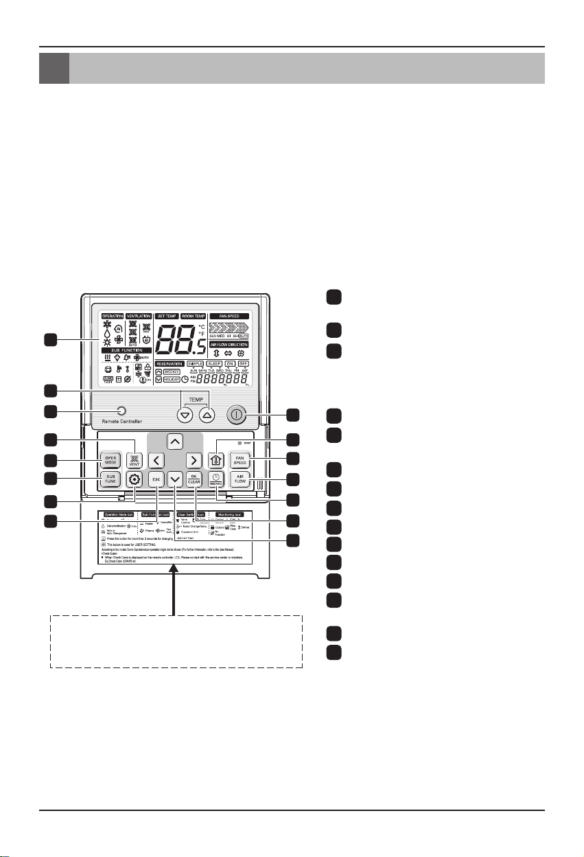
1. Connect the power and turn on with the wired remote controller(PQRCUSA0/1).
2. Check the AHU(Field supply) and outdoor unit operation when the wired remote
controller (PQRCUSA0/1) is controlled.
OPERATION INDICATION
1
SCREEN
2
SET TEMPERATURE Button
WIRELESS REMOTE
3
CONTROLLER RECEIVER
• Some products don't receive the
wireless signals.
4
VENTILATION Button
5
OPERATION MODE SELECTION
Button
6
SUBFUNCTION Button
7
FUNCTION SETTING Button
EXIT Button
* For more detailed function of the wired remote controller, refer to the Owner's &
Installation manual supplied with the wired remote controller.
* Button ③,④,,⑫ on the wired remote controller(PQRCUSA0/1) is not operated.
8
ON/ OFF Button
9
10
ROOM TEMPERATURE Button
11
FAN SPEED Button
12
AIR FLOW Button
13
RESERVATION/ TIME SETTING
Button
14
SETTING/ CANCEL Button
15
UP, DOWN, LEFT, RIGHT Button
(Do not operate)
(Do not operate)
(Do not operate)
18 AHU Control Kit

Troubleshooting
Problem Cause Remedy
No power supply Check the electrical connection and voltage of the
AHU Control Kit
does not work
Wiring is wrong Check the electrical connection of the Control kit
AHU Control Kit is broken Check the electrical and mechanical part.
power supply.
(Refer to the circuit diagram of the Control Kit)
Troubleshooting
Installation Manual 19

 Loading...