

LG PTND01B0E Installation Manual

P/NO : MFL62171718
INSTALLATION MANUAL
Applied(AHU)
Control Kit
AIR
CONDITIONER
www.lg.com
Please read this installation manual completely before installing the product.
Installation work must be performed in accordance with the national wiring
standards by authorized personnel only.
Please retain this installation manual for future reference after reading it
thoroughly.
ENGLISH
ESPAÑOL

• Do not cool excessively indoors. This may be harmful for your health and may consume more
electricity.
• Block sunlight with blinds or curtains while you are operating the equipment.
• Keep doors or windows closed tightly while you are operating the equipment.
• Adjust the direction of the air flow vertically or horizontally to circulate indoor air.
• Speed up the fan to cool or warm indoor air quickly, in a short period of time.
• Clean the air filter once every 2 weeks. Dust and impurities collected in the air filter may block the
air flow or weaken the cooling / dehumidifying functions.
For your records
Staple your receipt to this page in case you need it to prove the date of purchase or for warranty
purposes. Write the model number and the serial number here:
Model number :
Serial number :
You can find them on a label on the side of each unit.
Dealer’s name :
Date of purchase :
Here are some tips that will help you minimize the power consumption when you use the air
conditioner. You can use your equipment more efficiently by referring to the instructions
below:
TIPS FOR SAVING ENERGY
TIPS FOR SAVING ENERGY
2
ENGLISH

3
IMPORTANT SAFETY INSTRUCTIONS
READ ALL INSTRUCTIONS BEFORE USING THE APPLIANCE.
Always comply with the following precautions to avoid dangerous situations and ensure peak
performance of your product.
WARNING
It can result in serious injury or death when the directions are ignored.
CAUTION
It can result in minor injury or product damage when the directions are ignored.
WARNING
• Installation or repairs made by unqualified persons can result in hazards to you and others.
• Installation must conform with local building codes or, in the absence of local codes.
• The information contained in the manual is intended for use by a qualified service technician
familiar with safety procedures and equipped with the proper tools and test instruments.
• Failure to carefully read and follow all instructions in this manual can result in equipment malfunction, property damage, personal injury and/or death.
Installation
• Always perform grounding.
- Otherwise, it may cause electrical shock.
• Don’t use a power cord, a plug or a loose socket that is damaged.
- Otherwise, it may cause fire or electrical shock.
• For installation of the product, always contact the service center or a professional installation
agency.
- Otherwise, it may cause fire, electrical shock, explosion or injury.
• Securely attach the electrical part cover to AHU Comm. Kit.
- If the electric part cover of AHU Comm. Kit is not attached securely, it could result in a fire or
electric shock due to dust, water, etc.
• Always install an air leakage breaker and a dedicated switching board.
- No installation may cause a fire and electrical shock.
• Do not keep or use flammable gases or combustibles near the equipment.
- Otherwise, it may cause a fire or the failure of product.
• Do not install, remove or reinstall the unit by yourself.
- Otherwise, it may cause a fire, electrical shock, explosion or injury.
• Do not disassemble or repair the product randomly.
- It will cause a fire or electrical shock.
• Do not install the product in a place where there is the concern of falling down.
- Otherwise, it may result in personal injury.
• Use caution when unpacking and installing.
- Sharp edges may cause injury.
!
!
!
IMPORTANT SAFETY INSTRUCTIONS
ENGLISH

Operation
• Do not share the outlet with other appliances.
- It will cause an electric shock or a fire due to heat generation.
• Do not use the damaged power cord.
- Otherwise, it may cause a fire or electrical shock.
• Do not modify or extend the power cord randomly.
- Otherwise, it may cause a fire or electrical shock.
• Take care so that the power cord may not be pulled during operation.
- Otherwise, it may cause a fire or electrical shock.
• Unplug the unit if strange sounds, smell, or smoke comes from it.
- Otherwise, it may cause electrical shock or a fire.
• Keep flames away.
- Otherwise, may occur a fire.
• Take the power plug out if necessary, holding the head of the plug and do not touch it with
wet hands.
- Otherwise, it may cause a fire or electrical shock.
• Do not use the power cord near the heating tools.
- Otherwise, it may cause a fire and electrical shock.
• Do not allow water to run into electrical parts.
- Otherwise, it may cause the failure of machine or electrical shock.
• Hold the plug by the head when taking it out.
- It may cause electric shock and damage.
• Be cautious that water could not enter the product.
- Otherwise, it may cause a fire electrical shock or product damage.
• Do not step on the indoor/outdoor unit and do not put anything on it.
- It may cause an injury through dropping of the unit or falling down.
• Do not place a heavy object on the power cord.
- Otherwise, it may cause a fire or electrical shock.
• When the product is submerged into water, always contact the service center.
- Otherwise, it may cause a fire or electrical shock.
IMPORTANT SAFETY INSTRUCTIONS
4
ENGLISH

5
2 TIPS FOR SAVING
ENERGY
3 IMPORTANT SAFETY
INSTRUCTIONS
6 INSTALLATION STRUC-
TURE
6 Installation structure diagram
6 Cautions in installation structuring
7 Basic components provided
8 Product structure diagram
9 PRODUCT SPECIFICA-
TION
10 WIRING DIAGRAM
11 INSTALLATION
PROCESS DIAGRAM
12 CONNECT WITH AN
INVERTER DRIVE KIT
12 Connect a Control Kit with Inverter
Drive Kits
13 Set up an inverter drive Kit addresses
14 Set up an inverter drive Kit capacities
15 Set up an inverter drive kit RPM Hz
(when DI contact point is used)
17 7-Segment display information
18 Connection method between
DDC(automated control) and an inverter drive kit
20 ELECTRICITY WIRING
20 Cautions
21 Electricity wiring
23 APPENDIX
23 Guide for HMI frequency setup
24 Self Diagnosis Function
TABLE OF CONTENTS
TABLE OF CONTENTS
ENGLISH
6
INSTALLATION STRUCTURE
ENGLISH
INSTALLATION STRUCTURE
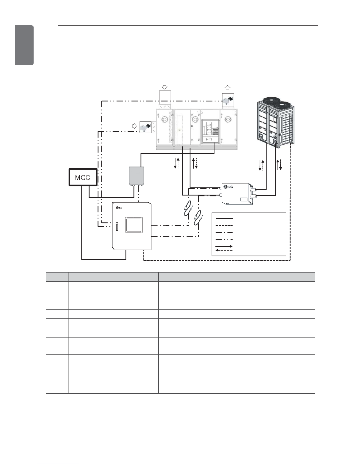
Installation structure diagram
Cautions in installation structuring
• A facility company is responsible for MCC construction work, and a separate discussion should
be made before an installation.
• A temperature sensor or a temperature/humidity sensor should be installed to at SA (supply air)
/ RA (return air) ducks to ensure a normal operation.
saoa
ra
Power line
①
②
③
Communication line
Piping sensor
Temperature/humidity sensor
Refrigerant piping
⑤
⑥
⑦-1
⑦-2
⑧
⑨
⑩
④
NO. Item Specification
①
AIR HANDLING UNIT -
②
Control Kit PRCKD42E
③
Expansion Kit PATX13A0E/20A0E/25A0E/35A0E/50A0E
④
Outdoor unit MULTI V
⑤
Piping temperature sensor IN Sensor : Ø 5, length : 10 m, line color : Black
⑥
Piping temperature sensor OUT Sensor : Ø 7, length : 10 m, line color : Red
⑦-1, 2
Temperature/humidity sensor
RA, SA
-40 °C ~ 70 °C, RH 0 ~ 95 %/AC 24 V/DC 0 ~ 10 V
⑧
Supply air fan -
⑨
Inverter drive KIT PTND01B0E
⑩
MCC MCC distributing board PANEL
INSTALLATION STRUCTURE
7
ENGLISH
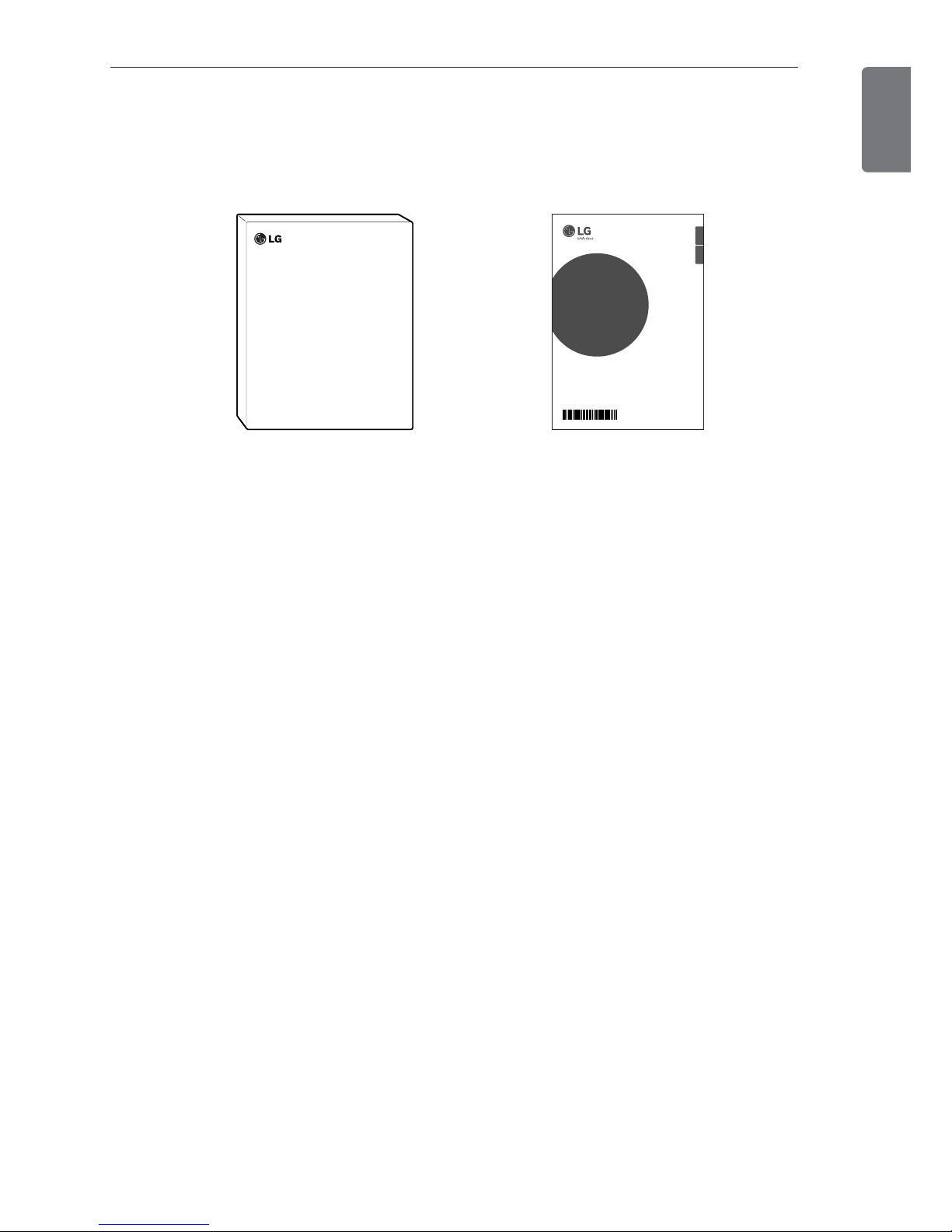
Basic components provided
• The components of an inverter drive kit are as below. Please, check components when you
open the box.
<Inverter Drive KIT> <Installation/User Manual>
P/NO : MFL62171718
INSTALLATION MANUAL
Applied(AHU)
Control Kit
AIR
CONDITIONER
www.lg.com
Please read this installation manual completely before installing the product.
Installation work must be performed in accordance with the national wiring
standards by authorized personnel only.
Please retain this installation manual for future reference after reading it
thoroughly.
ENGLISH ESPAÑOL
8
INSTALLATION STRUCTURE
ENGLISH
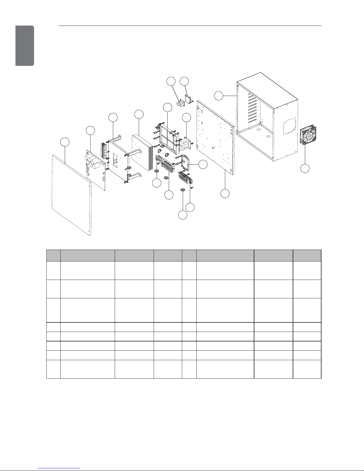
Product structure diagram
• PTND01B0E
1
2
3
4
5
8
9
10
7
13
11
12
14
6
15
16
No. Parts name Specification Quantity No. Parts name Specification Quantity
①
Cover - 1
⑨
Main Power Line
Terminal Block
100 A, 6PIN 1
②
Inverter PCB 8 kW 1
⑩
Communication
Terminal Block
25 A, 13PIN 1
③
Inverter PCB Fixing
Bracket
- 1
⑪
Rubber Bush - 3
④
Heatsink - 1
⑫
Middle Panel - 1
⑤
Noise Filter AC 35 A 1
⑬
Outer Box - 1
⑥
Reactor - 1
⑭
Cooling Fan AC 25 W 1
⑦
Interface PCB DC 1
⑮
Trans AC 220 V 1
⑧
Motor Power Line
Terminal Block
30 A, 4PIN 1
⑯
Trans Fixing Bracket - 1
PRODUCT SPECIFICATION
9
ENGLISH
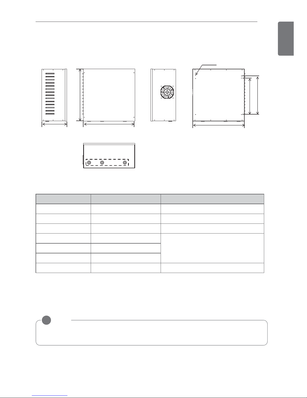
PRODUCT SPECIFICATION
NOTE
!
Input wires into the holes in G could change by an installation condition, and, please, use
flexible pipes and connectors which fit with respective holes.
Classification Spec. Explanation
A (mm) 493.4 Width
B (mm) 496.8 Height
C (mm) 237.2 Depth
D (mm) 437.8
Distance between AHU fastening holesE (mm) 346.8
F (mm) 366.8
G Ø 28 Wires input Parts
<left side> <front side>
<bottom side>
<right side> <back side>
c a
b
6-Φ6 Hole
d
e
f
g
 Loading...