


P/NO : MFL62049604
www.lge.com
INSTALLATION MANUAL
AIR CONDITIONER
• Please read this installation manual completely before installing the product.
• Installation work must be performed in accordance with the national wiring
standards by authorized personnel only.
• Please retain this installation manual for future reference after reading it
thoroughly.
TYPE : AHU CONTROL KIT
ENGLISH
ITALIANO
ESPAÑOL FRANÇAIS
PORTUGUESE

2 AHU CONTROL KIT
AHU CONTROL KIT Installation Manual
TABLE OF CONTENTS
Safety Precautions...............................................................................3
Installation configuration ......................................................................5
Supplies ...............................................................................................6
Wiring diagram.....................................................................................9
Installation flowchart...........................................................................13
CONTROL KIT Installation .................................................................14
Pipe temperature sensor connection .................................................16
Outdoor communication cable connection.........................................17
Precaution..........................................................................................18
AHU sensor specification...................................................................20
AHU sensor secondary cover Installation (Outdoor Installation)........21
AHU sensor connection .....................................................................22
ACP/BACnet gateway connection......................................................28
AHU controller setting ........................................................................29
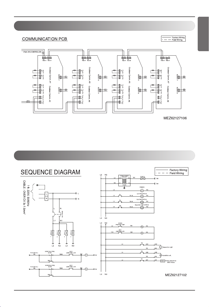
Communication PCB setting ..............................................................34
Electric wiring work ............................................................................36
Test run ..............................................................................................42
Safety Precautions
Installation Manual 3
ENGLISH
■ Installation
Safety Precautions
To prevent injury to the user or other people and property damage, the following instructions must be followed.
■ Incorrect operation due to ignoring instruction will cause harm or damage. The seriousness is
classified by the following indications.
■ Meanings of symbols used in this manual are as shown below.
WARNING
CAUTION
This symbol indicates the possibility of death or serious injury.
This symbol indicates the possibility of injury or damage.
Be sure not to do.
Be sure to follow the instruction.
WARNING
Do not use the existing manifold gauge for
R22 refrigerant.
• To charge the refrigerant stably, always
use the manifold gauge for high pressure
(R410A).
Install the air conditioner at a designated
location using the designated material.
• Heat exchanger inlet/outlet pipe location.
Do not store or use
flammable gas or volatile
substance near the air
conditioner.
• It can cause a fire or problem
to the product.
Do not mix existing R22 pipe
and installation products for
the installation.
• When you mix the mineral oil
of R22 and R410A oil (PVE), it
can decompose with water to
cause problems to the product.
Do not mix other refrigerant
with the designated
refrigerant (R410A) during
the installation or moving
the air conditioner.
• When other refrigerant is
mixed with the original
refrigerant, it can cause a
problem in the refrigerant cycle
and damage the product.
System air conditioner can
only be installed by
specialized service provider
with air condition
installation certifications.
• Inappropriate installation can
cause leakage, fire and
electric shock.
When moving or reinstalling
the air conditioner, please
contact the
MULTI VTM AHU
installation service provider.
• Inappropriate installation can
cause leakage, fire and
electric shock.
Do not disassemble, repair
or reconfigure the product
arbitrarily.
• It can cause a fire and electric
shock.
Safety Precautions
4 AHU CONTROL KIT
■ Operation
■ Installation
Do not install the air conditioner outdoors.
• If installed outdoor inevitably, consult Multi
VTM
AHU installation service provider.
Do not let any worker or user climb on top of
the product.
• The person can get seriously injured.
Make sure that water does
not get inside the product
(Controller). Especially, do
not clean the product with
water.
• It can cause electric shock and
problems.
When the air conditioner is
submersed in water, always
consult
MULTI VTM AHU
installation service provider.
• It can cause a fire and electric
shock.
Do not keep any heating
devices near the product.
• It can cause a fire.
After the product installation
and repair, always check for
gas leakage.
• It can cause problems in the
product.
When installing the product,
always make sure to level to
the product.
• It can cause vibration and
leakage.
Do not install the product
where flammable gas leaks.
• It can cause a fire and
problems to the product.
■ Operation
If the refrigerant leaked while installing the product, always ventilate the room.
• The refrigerant gas can react with the fire to turn into hazardous gas to cause an accident.
CAUTION
Installation Manual 5
Installation Scene
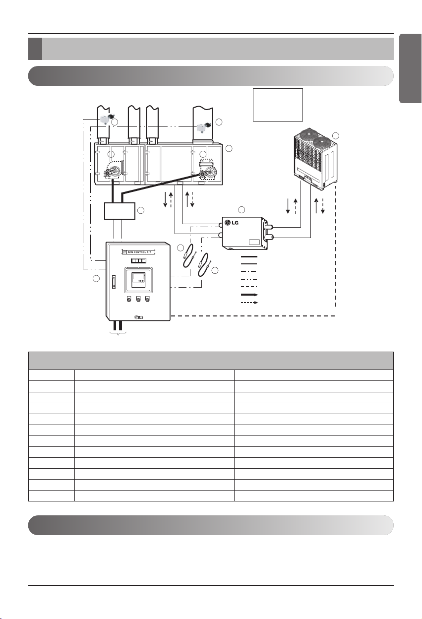
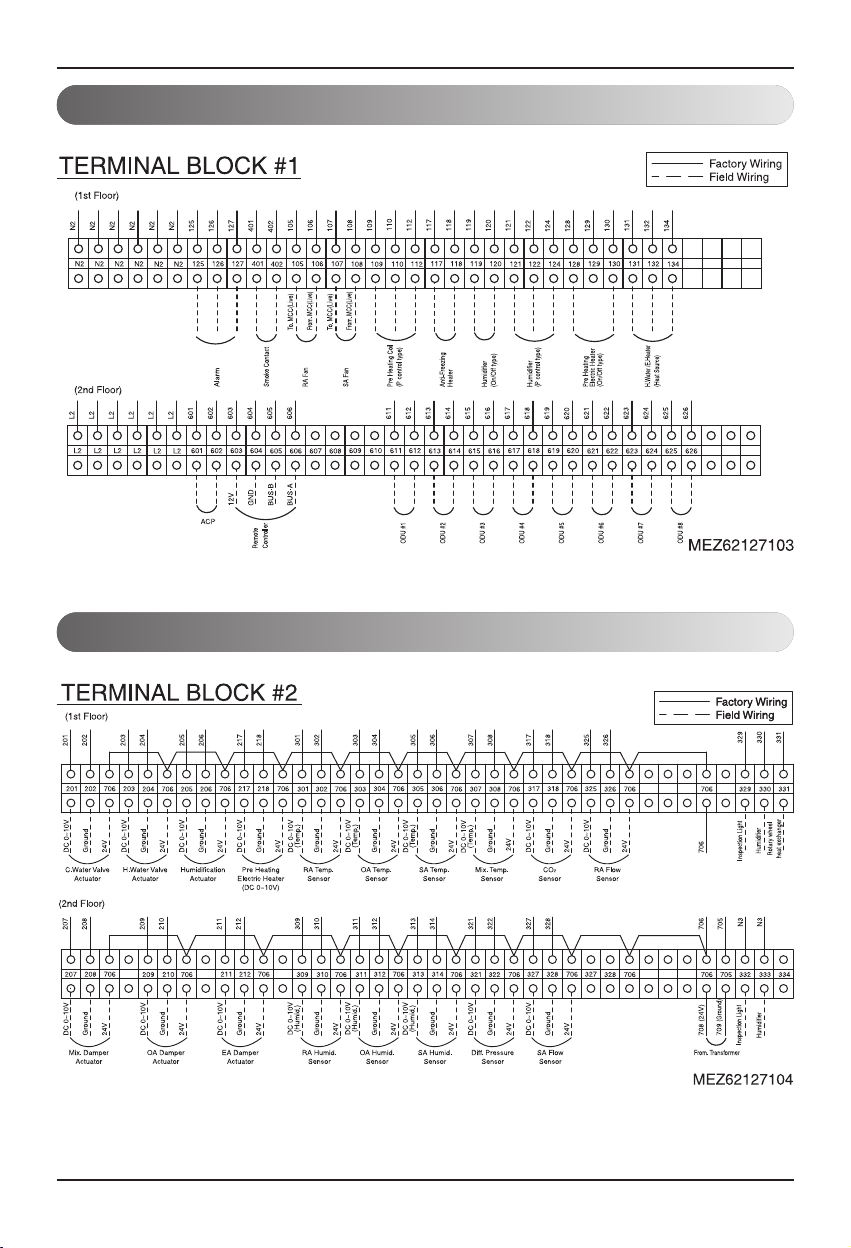
Installation configuration
RA
OA
SA
220V0V/
60Hz/1P1PHASE
8 -1
No. Name Remarks
①
Air Handling Unit -
②
CONTROL KIT PRCKD20E / PRCKD40E
③
EXPANSION KIT PATX13A0E/20A0E/25A0E/35A0E
④
Outdoor unit Multi V
⑤
Pipe temperature sensor IN Sensor: Ø5, Length: 10m,Cable color: Black
⑥
Pipe temperature sensor OUT Sensor: Ø7, Length: 10m, Cable color: Red
⑦
-1 Temperature sensor RA -50~50°C/ AC 24V / DC 0~10V
⑦
-2 Temperature sensor SA -50~50°C/ AC 24V / DC 0~10V
⑧
-1 Return Fan -
⑧
-2 Supply Fan -
⑨
MCC MCC
Installation components
ENGLISH
Installation configuration diagram
Precaution during installation configuration
1. MCC is the construction of the equipment by the equipment provider and must be separately discussed before
the installation.
2. Temperature or Temperature/Humidity sensor must be installed on the SA/RA duct for normal operation.
RA
2
EAEAOA
7 -1 7 -2
8 -1
9
MCC
SA
8 -2
5
1
3
6
• RA: Return air
• EA: Exhaust air
• OA: Outdoor air
• SA: Supply air
Power cable
Refrigerant pipe
Pipe temperature sensor
Signal cable
Communication cable
Refrigerant flow (Air conditioning)
Refrigerant flow (Heating)
4
60H
Basic parts supplied
Sensor (Separately sold)
• To operate the product, you must separately purchase and install the following temperature or
temperature/humidity sensor.
• Separate specification and installation location for the applied sensor can be checked from
ʻAHU sensor specification”.
6 AHU CONTROL KIT
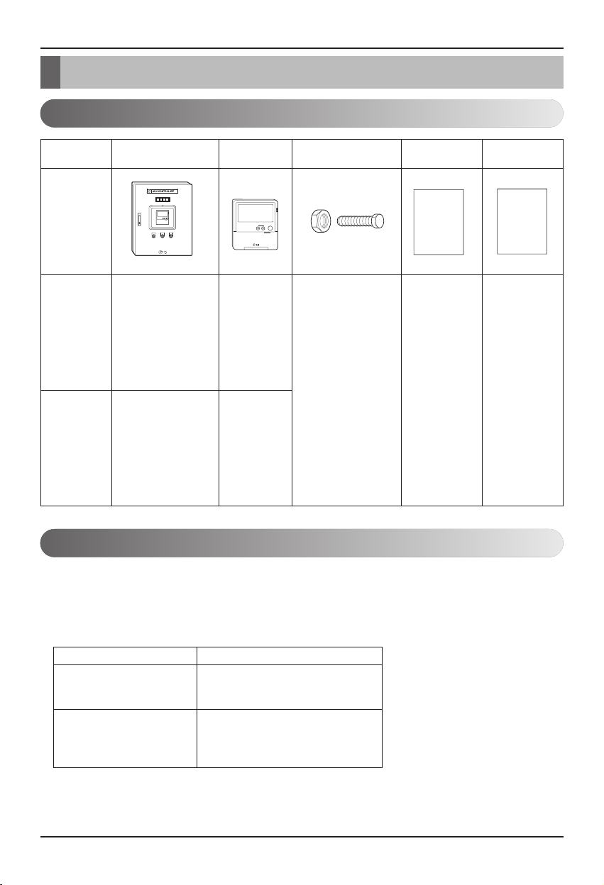
Supplies
Supplies
CONTROL KIT
- Quantity: 1EA
- Maximum number of
outdoor units that
can be connected:
- Quantity: 4EA
- Bolt quantity: 4EA
Specification:
M10/70mm
- Nut quantity:4EA
Specification: M10
- Quantity: 1EA
- Quantity: 1EA - Quantity: 1EA
- Quantity: 1EA
- Quantity: 1EA
- Maximum number of
outdoor units that
can be connected:
- Quantity: 8EA
Model name
PRCKD20E
PRCKD40EE
Wired remote
controller
Installation bolt/nut
Installation
manual
User manual
٦ʭܖۿ@@@@@@@@@ڒ۾O܄ݖ
Installation
manual
User
manual
Item Specification
Temperature sensor - Power: AC24V
- Output signal: DC 0~10V
- Temperature range: -50~50°C
Temperature/ - Power: AC24V
Humidity sensor - Output signal: DC 0~10V
- Temperature range: -40~70°C
- Humidity range: 0~95%RH
Supplies
Installation Manual 7
Product configuration
ENGLISH
PRCKD20E
* ( ) refers to the quantity applied to the PRCKD40E model.
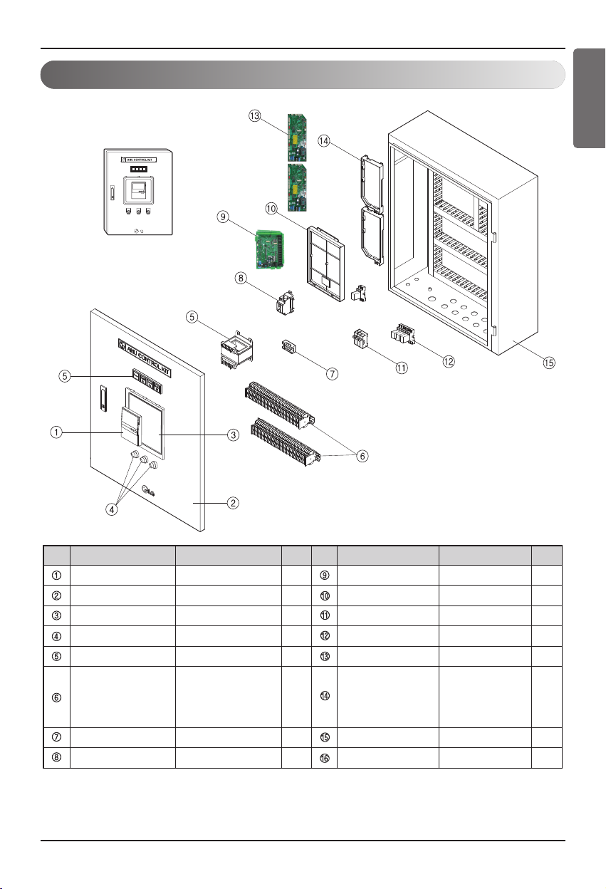
No. Part name
Wired remote controller
Door
Wired remote controller shield box
Selection switch
Lamp
Transformer
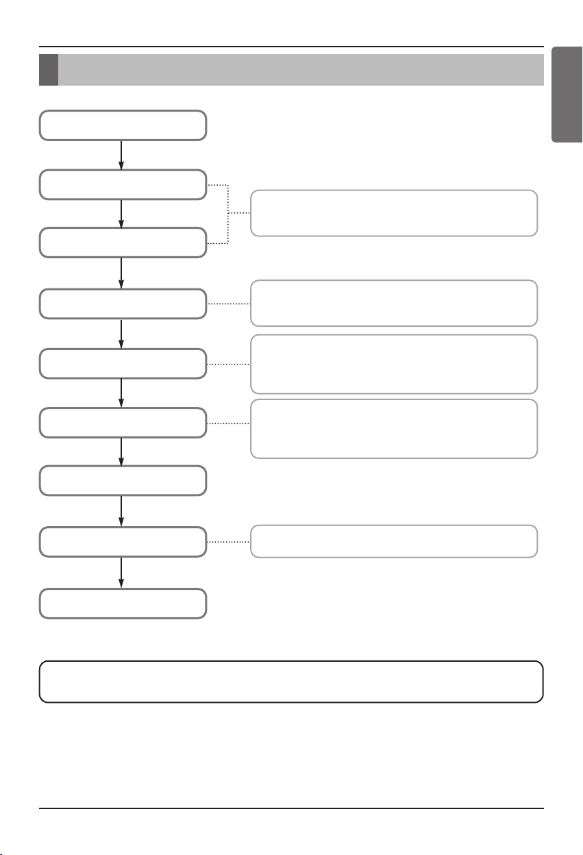
Terminal block #1
Terminal block #2
Specification
-1
1.6T 1
Polycarbonate, IP65
ON/OFF 3 250V, 5A 5
Power/SA/RA 4 5A 4
Input: 220V
Output: 24V
Capacity: 100VA
15A * 1.25mm
20A * 1.25mm
Quantity
No.
1
1 -
2
2 2(4)
2
1 1.6T 1
Part name Specification
Wiring circuit breaker
AHU Controller -
Controller Case
Fuse
Relay
Communication PCB
Communication PCB case
Control box
Quantity
15A 1
-
-
1
1
2(4)
Supplies
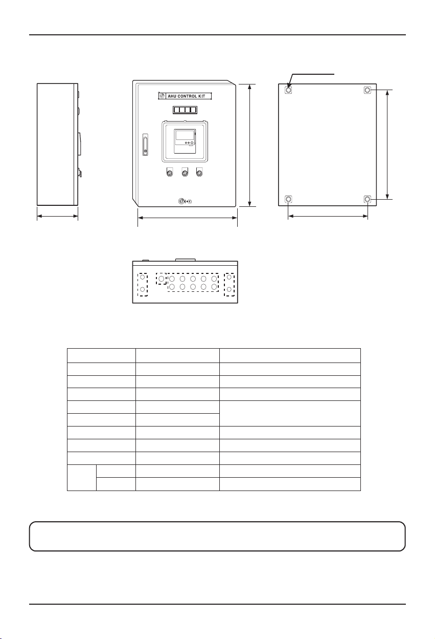
8 AHU CONTROL KIT
(Side) (Front) (Rear)
(Floor)
PRCKD20E / PRCKD40E
Remarks
A (mm) 600 Length
B (mm) 750 Height
C (mm) 280 Width
D (mm) 500
Hole connecting to AHU
E (mm) 650
F 4-Ø16 Hole Pipe sensor connector
G 10-Ø25 Hole Sensor/Communication cable connector
H Ø30 Hole Power cable connector
Weight
Product 43.5 Product weight
Packaging 48 Weight after packaging
■ Depending on the installation personnel, the cable drawn to the F/G/H hole can be
changed, and use the flexible pipe and connector that fits each hole.
4-Ø12 Hole
BE
CD
FH G F
A
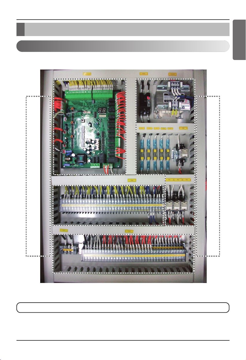
Wiring diagram
Installation Manual 9
ENGLISH
Wiring diagram
Part diagram
PRCKD40E
Communication PCB part #2
Safety part
AHU controller part
Communication PCB part
Terminal block part #2
Terminal block part #1
■ Communication PCB #1 part is not attached to the PRCKD20E model.
AHU controller part
Communication PCB part
Communication PCB part
Terminal block part #2
Terminal block part #2
Safety part
Safety partAHU controller part
Communication PCB part #2
Communication PCB part #2
Terminal block part #1
Terminal block part #1
(Inside product)
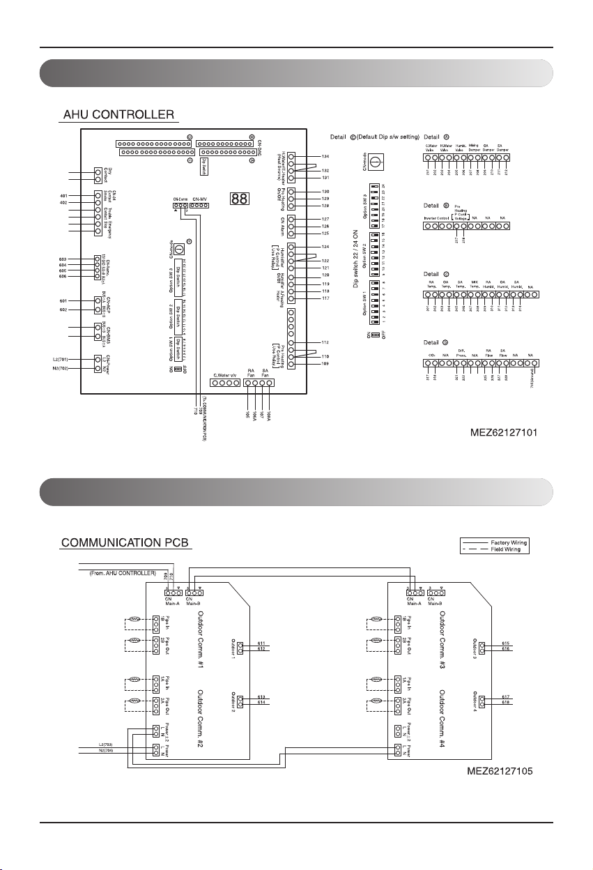
Wiring diagram
10 AHU CONTROL KIT
AHU controller part
Communication PCB part (PRCKD20E)
Wiring diagram
Installation Manual 11
ENGLISH
Communication PCB part (PRCKD40E)
Safety part (Transformer, wiring circuit breaker)
Wiring diagram
12 AHU CONTROL KIT
Terminal block part #1
Terminal block part #2
Installation flowchart
Installation Manual 13
ENGLISH
Installation flowchart
■ This order can change depending on the construction site. Therefore please read
the installation manual prior to the applicable work.
CONTROL KIT installation
Pipe temperature
sensor connection
Outdoor unit communication
cable connection
AHU sensor connection
AHU controller setting
Communication PCB setting
• Because 2 Outdoor units can be connected to 1 communication PCB,
be careful not to get the pipe temperature sensor and communication
cable connection to 1 Outdoor unit mi
• Temperature sensor that fits the specification must be installed in the
SA duct and RA duct.
(Specification: -50~50°C/ AC 24V / DC 0~10V)
• Install the temperature sensor only for the SA/RA duct and Dip switch
does not need to be set.
• Depending on the installation site, if the optional sensor is applied,
set the dip switc
• Be careful of Dip switch setting according to whether Outdoor unit is
connected or not.
• When connecting Outdoor unit, make sure to set Rotary switch
erently.
diff
xed and connected.
h according to the setting method.
Electric wiring
Outdoor unit address se
Operation check
tting
• After completing the installation of CONTROL KIT, always set the
address of Outdoor unit.
14 AHU CONTROL KIT
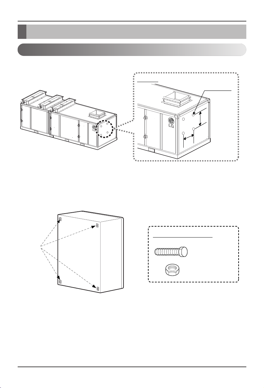
1. Check the location to install CONTROL KIT from the AHU product.
2. Check location of the hole on the rear side of CONTROL KIT and check whether accessories
exist for the installation.
CONTROL KIT Installation
Product installation location check
CONTROL KIT Installation
Detail
650
mm
500
mm
4-Ø12 Hole
4 holes
Installation bolt (4EA)
Installation nut (4EA)
Installation accessories
<AHU>
<Rear side of CONTROL KIT>
Installation location
(When installing on the side of the product)
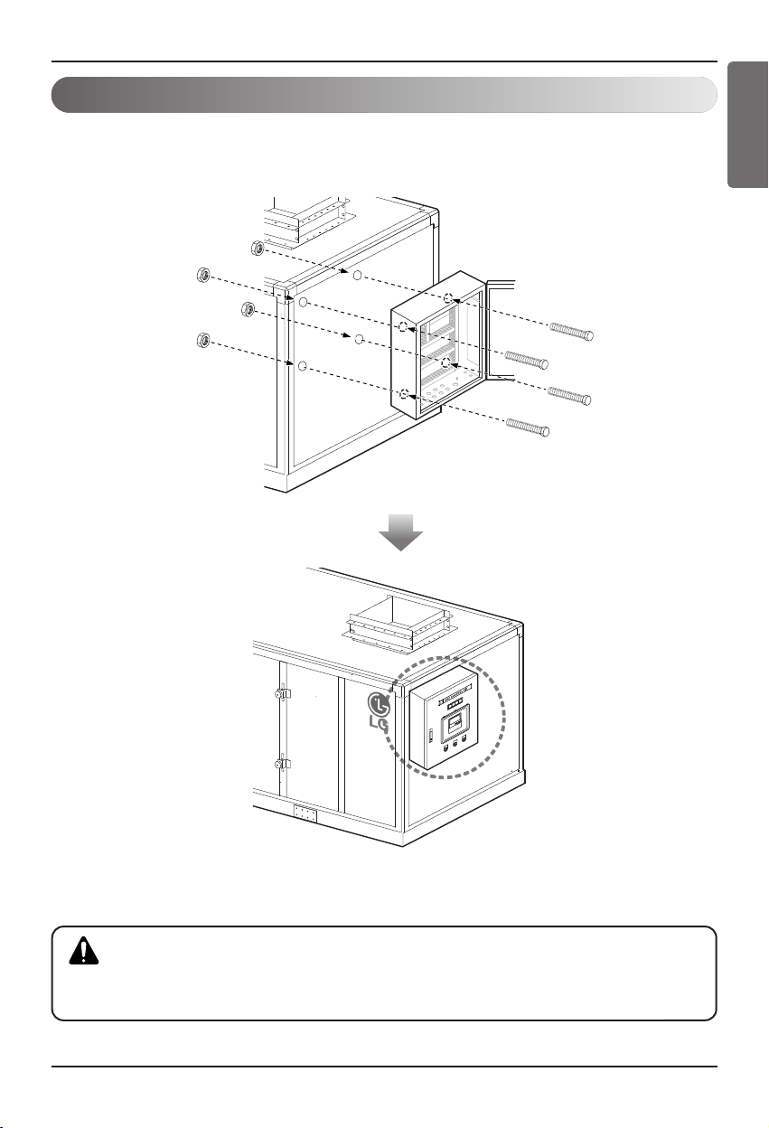
CONTROL KIT Installation
Installation Manual 15
ENGLISH
1. Punch the AHU panel according to the punched holes in the Control kit, and after matching
the punch locations, fix with bolts and nuts.
Product installation
<Installation complete>
■ Do not install the product by yourself.
■ After installing the product, check whether it is fixed well.
CAUTION
16 AHU CONTROL KIT
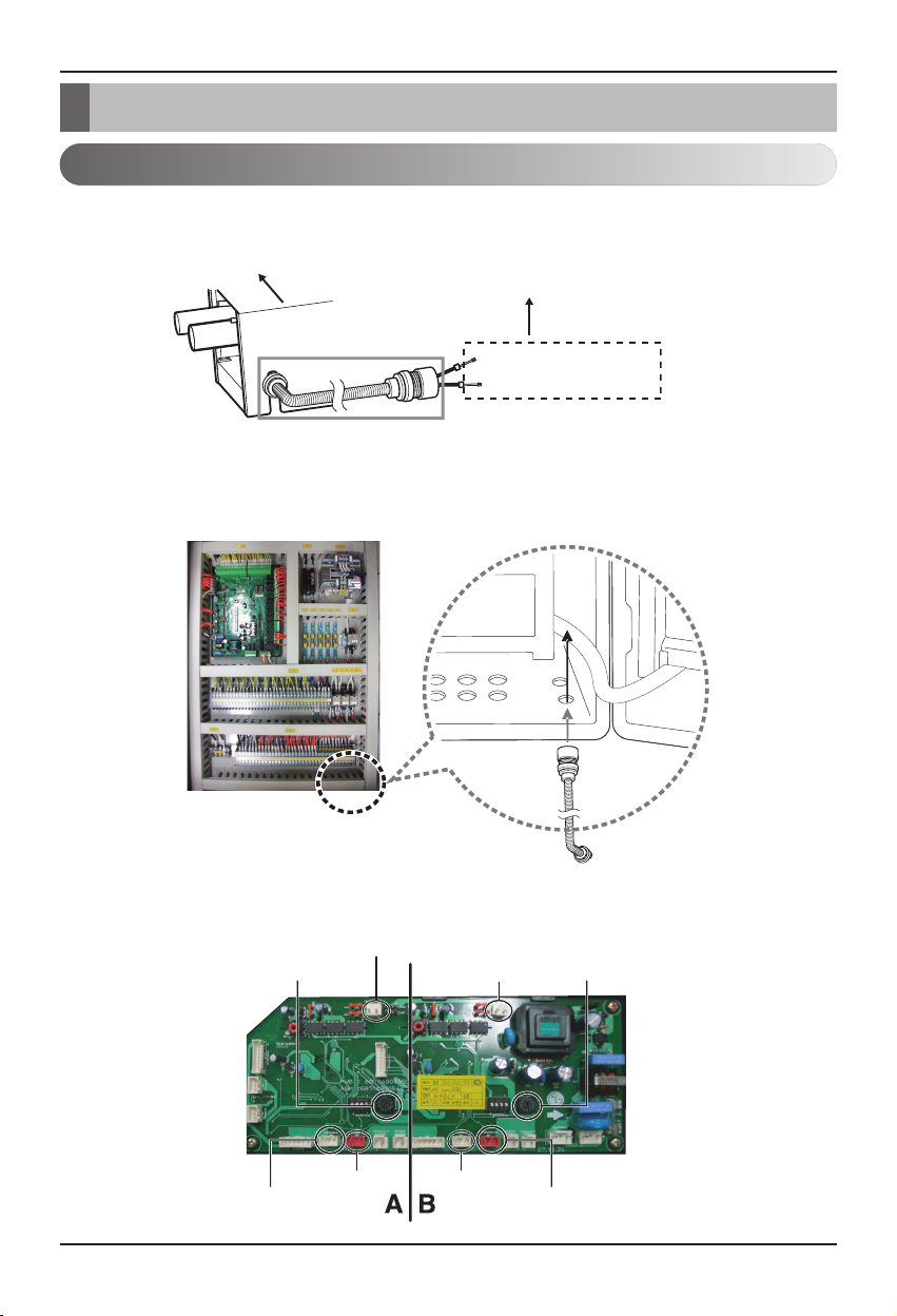
Pipe temperature sensor connection
Pipe temperature sensor connection
Pipe temperature sensor connection
2. Connect the flexible pipe and the connector (Ø16, Installed on site) included from
EXPANSION KIT to CONTROL KIT.
3. Classify the IN/OUT of the pipe temperature sensor, and connect to the connector on the
communication PCB.
Flexible pipe and connector: Ø16(Supplied on site)
Pipe temperature sensor IN
Pipe temperature sensor OUT
Rotary switch #1
Pipe temperature sensor #1 IN Pipe temperature sensor #2 OUT
Pipe temperature sensor #1 OUT Pipe temperature sensor #2 IN
Rotary switch #2
Outdoor unit
communication cable #1
Outdoor unit
communication cable #2
EXPANSION KIT
(PATX13A0E/20A0E/25A0E/35A0E)
• Pipe temperature sensor IN: Sensor Ø5, Length 10m, Cable color Black
• Pipe temperature sensor OUT: Sensor Ø7, Length 10m, Cable color Red
1. Check the IN/OUT of the pipe temperature sensor connected to EXPANSION KIT.
 Loading...