

Page 1

LG
Dry contact for communication
Owner's & installation manual
LG
IMPORTANT
• Please read this manual completely before
installing the product.
• Installation work must be performed in
accordance with the national wiring standards
by authorized personnel only.
• Please retain this installation manual for future
reference after reading it thoroughly.
Visit us at : http://www.lgservice.com
Models: PQDSBC
Page 2

2 Dry contact for communication
Dry contact for communication Owner’s &installation manual
TABLE OF CONTENTS
■ Safety Precautions
.............................................................
3~4
■ Name of each part
..................................................................
5
■ Installation Method
.............................................................
6~7
Installation inside of the indoor unit..........................................................6
Installation outside of the indoor unit .......................................................7
■ Setting and using method
................................................
8~18
1. Power supply and indoor unit connection............................................8
2. Setting of Contact Signal Input ............................................................9
3. Setting the desired temperature ........................................................10
4. Control mode setting..........................................................................11
5. Indoor unit monitoring ........................................................................15
Page 3
Safety Precautions
Owner’s & installation manual 3
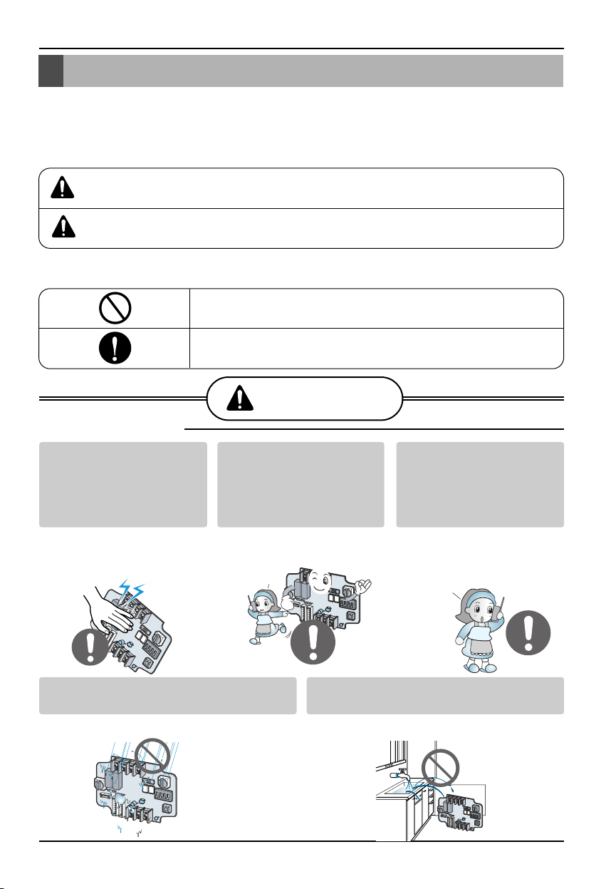
Do not touch the board
when the power is
connected.
•
It can cause a fire, electric
shock, explosion, injury and
problem to the product.
Always request for
installation of the product
to the service center or
the installation service
provider.
•
It can cause a fire, electric
shock, explosion and injury.
When reinstalling the
previously installed product,
request for service to the
service center or the
installation service provider.
•
It can cause a fire, electric
shock, explosion and injury.
■ During installation
Service center
Service center
Do not install the product where it can
be exposed to rain.
•
It can cause problems to the product.
Do not install the product in a humid
location.
•
It can cause problems to the product.
Safety Precautions
To prevent injury to the user or other people and property damage, the following instructions
must be followed.
■ Incorrect operation due to ignoring instruction will cause harm or damage. The seriousness is
classified by the following indications.
■ Meanings of symbols used in this manual are as shown below.
This symbol indicates the possibility of death or serious injury.
This symbol indicates the possibility of injury or damage.
Be sure not to do.
Be sure to follow the instruction.
WARNING
WARNING
CAUTION
Page 4
Safety Precautions
4 Dry contact for communication
■ During use
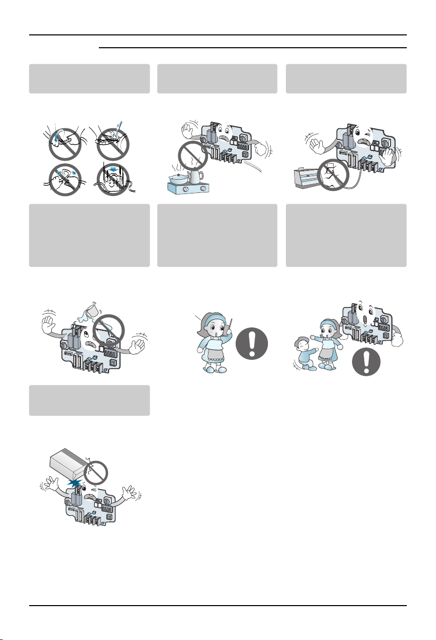
Do not modify or extend the
power cord.
• It can cause a fire and
electric shock.
Do not use any flaming
devices near the product.
• It can cause a fire.
Do not use any heating
devices near the power cord.
• It can cause a fire and
electric shock.
Do not pour water inside the
product.
• It can cause an electric
shock and problem to the
product.
When the product is
submersed in water, always
request for service to the
service center or the
installation service provider.
• It can cause a fire and
electric shock.
Make the children and the
elderly use the product with
the help of a guardian.
• It can cause a safety
accident and problems to the
product.
Do not give impact to the
product.
• It can cause problems to the
product.
Service center
Page 5
Name of each part
Owner’s & installation manual 5
Name of each part
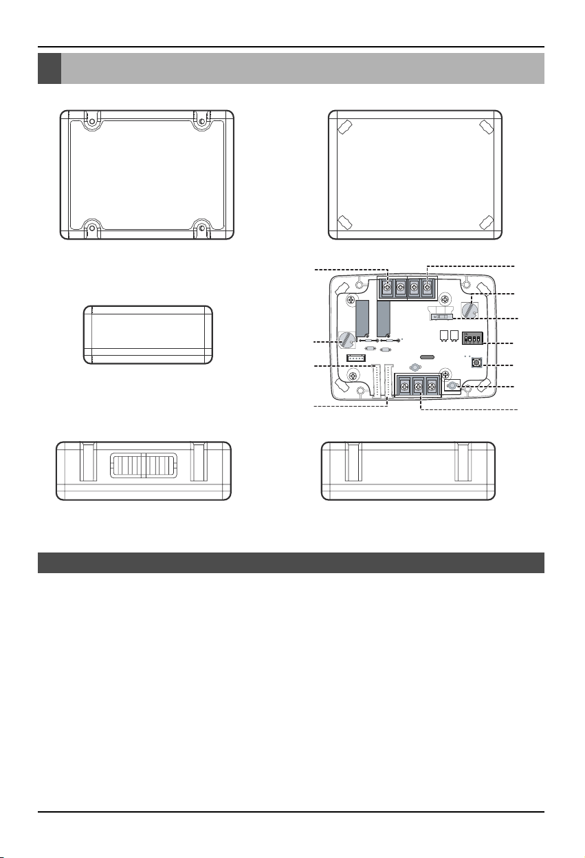
1. CN_INDOOR : Connect communication wire between indoor unit and Dry contact for communication
and supply power to Dry contact for communication
2. CN_PI485 : PI485 connector
3. CHANGE_OVER_SW : Switch to select voltage (5V-12V) of contact point
4. CN_CONTROL : Contact point signal input
5. CONTROL_MODE_SW : Switch to select the control mode
6. SETTING_SW : Switch to select whether to use set function of Dry contact for communication
7. TEMP_SETTING : Switch to set the desired temperature of the indoor unit
8. CN_OUT (O1, O2) : Connector to show whether the indoor unit is operating
9. CN_OUT (E3, E4) : Connector to show whether there is an error with the indoor unit
10. DISPLAY_LED : LED to display the status of the Dry contact for communication
11. RESET_SW : Reset switch
DRY CONTACT FOR COMMUNICATION (DRY_CONTACT FOR COMMUNICATION)
NOT
USB
e
CN_OUT
CHANGE
OVER_SW
VOLT
NON
VOLT
TEMP
SETTING
(Front case)
(Rear case)
(Top)
(Internal PCB board)
(Side) (Side)
1
2
5
8
9
7
3
6
11
10
4
Page 6
Installation Method
6 Dry contact for communication
Installation Method
Installation inside of the indoor unit
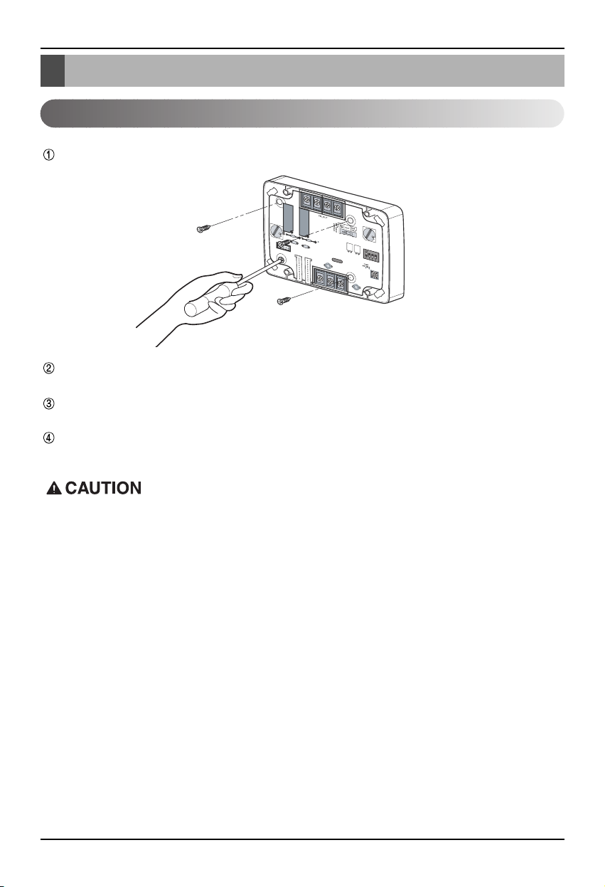
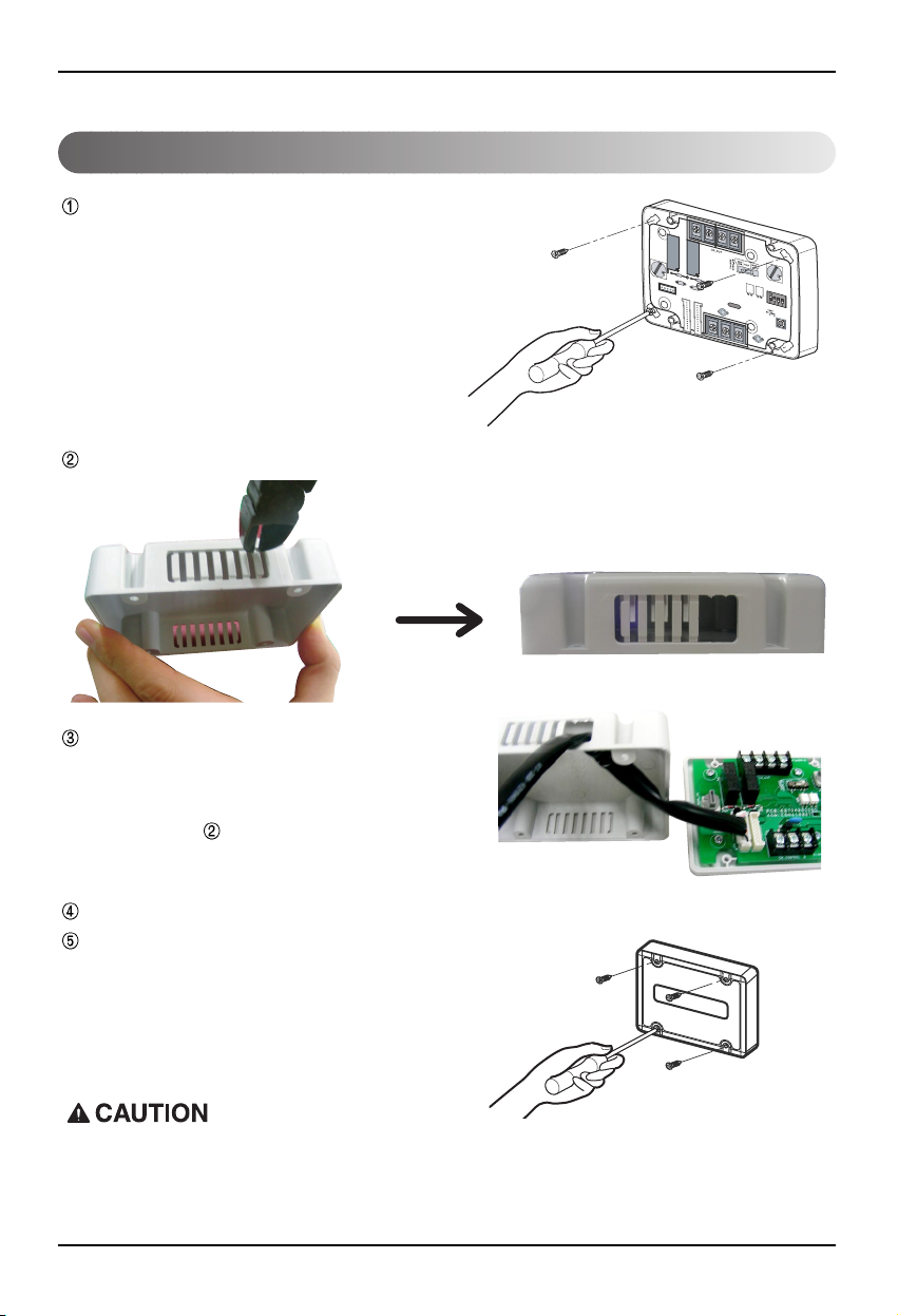
Loose 4 screws anchoring PCB and then separate the rear case and PCB
Connect the connection wires according to the instructions. (Please refer to Setting and Using
Method)
Perform the switch setting according to switch setting method. (Please refer to Setting and Using
Method)
Fix PCB on suitable space inside of the indoor unit.
1. Install the product on flat surface and install anchoring screws at more than 2 places. Otherwise
the central controller may not be anchored properly.
2. Do not tighten anchoring screws too tightly. It may cause deformation of the case.
3. Do not deform the case at random. It may cause malfunction of the central controller.
Page 7
Installation Method
Owner’s & installation manual 7
Installation outside of the indoor unit
Anchor the rear case of Dry Contact for
communication on the installation surface at
holes using anchor screws.
Connect connection wires according to the
instructions.
(Reference to Setting and Using Method)
Then, connect wire to PCB after going
through hole of .
Join the front case and the rear case, anchor
the front case at holes using anchor screws.
Please cut the pole which is located in side of the front case properly.
Perform the switch setting according to switch setting method. (Reference to Setting and Using Method)
DRY CONTACT UNIT
1. Install the product on flat surface and install anchoring screws at more than 2 places. Otherwise
the central controller may not be anchored properly.
2. Do not tighten anchoring screws too tightly. It may cause deformation of the case.
3. Do not deform the case at random. It may cause malfunction of the central controller.
Page 8
Setting and using method
Setting and using method
8 Dry contact for communication
1. Power supply and indoor unit connection
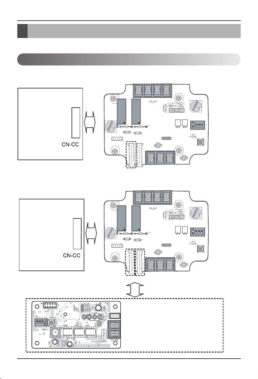
You must press the RESET switch when you are completed with all the settings to reflect the
settings.
■
When using the Dry contact for communication independently
■ When using with the central controller (Only when the indoor
unit PCB is a non-communication model)
Indoor unit
PCB
Indoor unit
PCB
PI485: Connect to central controller
CN_PI485
CN_INDOOR
CN_INDOOR
CN_INDOORCN_INDOOR
Page 9
Setting and using method
Owner’s & installation manual 9
2. Setting of Contact Signal Input
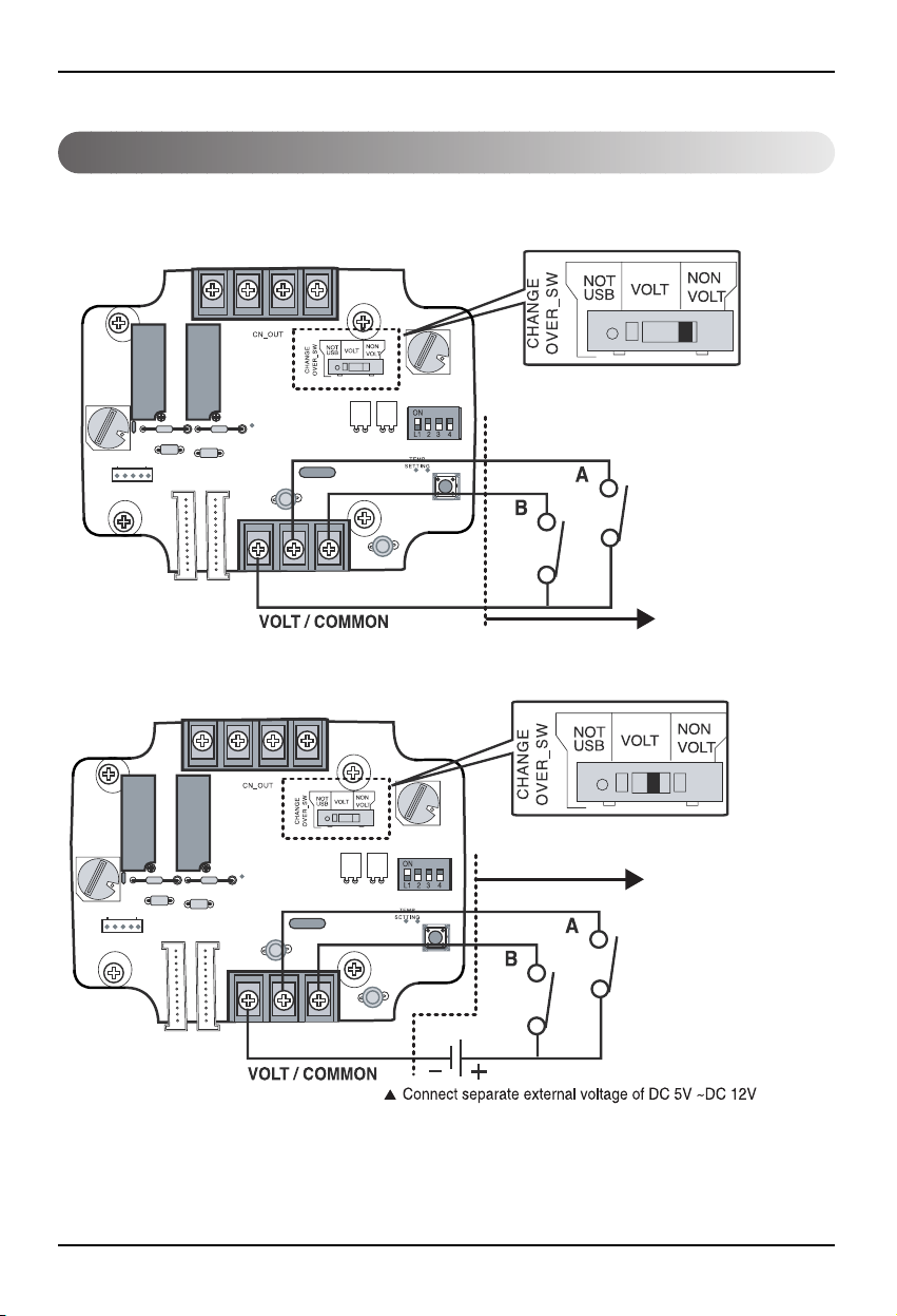
■ For no power contact point signal input
■ For power contact point signal input
LG does not
supply this section
(Local supply)
LG does not
supply this section
(Local supply)
Page 10
Setting and using method
10 Dry contact for communication
3. Setting the desired temperature
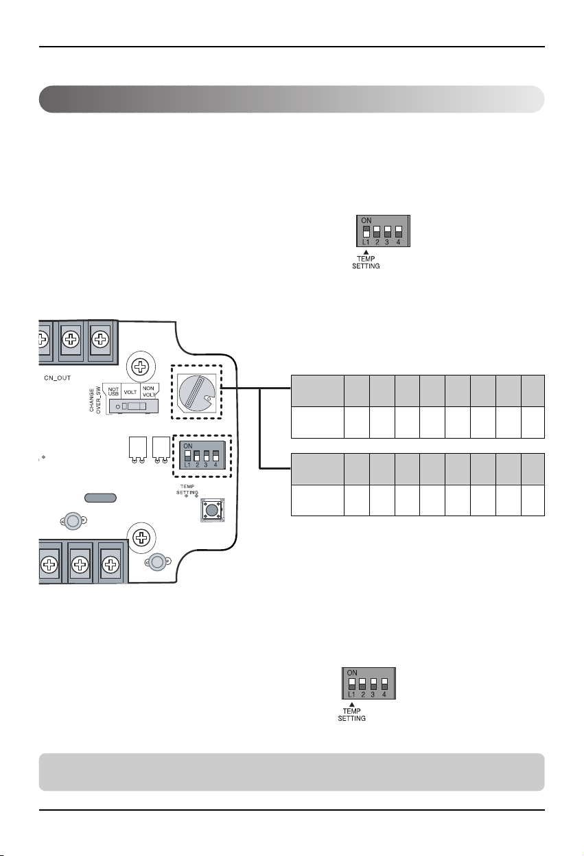
■ When setting the desired temperature of the Dry contact for
communication
: When operating the indoor unit, set the desired temperature according to the TEMP_SW setting.
When the indoor unit is unlocked, the desired temperature can be reset by other controller
1) Turn on the TEMP_SETTING switch of SETTING_SW.
2) Use the TEMP_SW to set the temperature as shown below.
■ When not using the desired temperature setting of Dry
contact for communication
1) Turn off the TEMP_SETTING switch of SETTING_SW.
➲ When operating the indoor unit initially in Dry contact for communication, set the desired
temperature to 18°C.
SETTING_SW
SETTING_SW
01234567
18 19 20 21 22 23 24 25
Desired temperature setting table
TEMP SW
setting
Temperature
setting(°C)
89ABCDEF
26 27 28 29 30 30 30 30
TEMP SW
setting
Temperature
setting(°C)
Page 11
Setting and using method
Owner’s & installation manual 11
4. Control mode setting
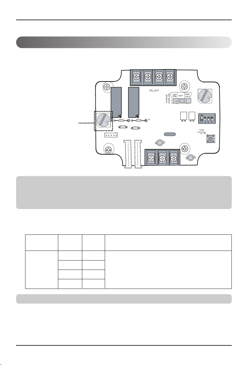
■ Use the CONTROL_MODE_SW to set the control mode you
want from 0~D.
■ Description of each control mode
1) Cancel mode for use of dry contact for communication
➲ Set this when the Dry contact for communication is connected but not used.
➲ Indoor control priority
Central control > Dry contact for communication > Wired/Wireless remote controller, indoor unit
button
➲ Dry contact for communication controls the indoor unit according to the applicable mode when there
is a change in input of A and B.
CONTROL_MODE_SW
Input A Input B Operating mode
OFF OFF
ON OFF
OFF ON
ON ON
The indoor unit cannot be controlled through the
Dry contact for communication
No change in indoor unit condition
CONTROL_
MODE S/W
0
Page 12
Setting and using method
12 Dry contact for communication
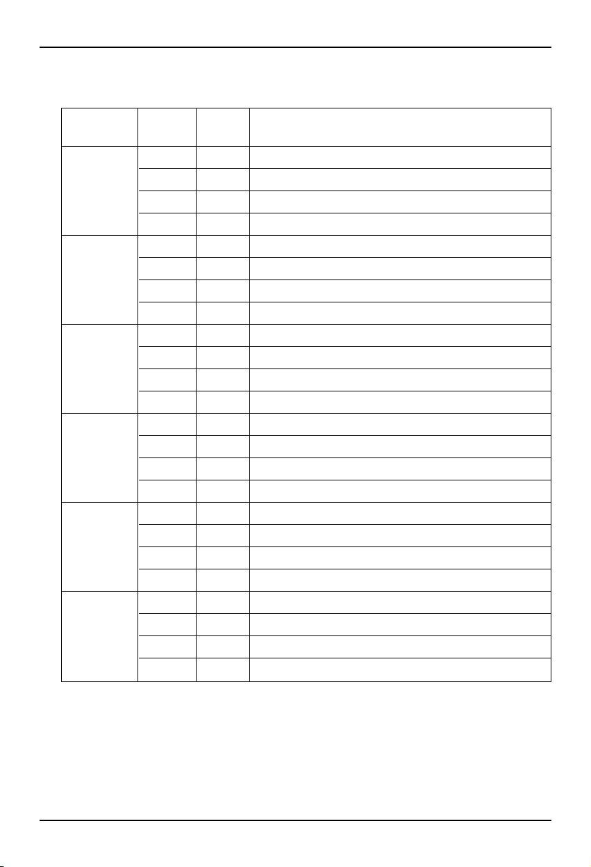
2) General mode
Input A Input B Operating mode
OFF OFF
ON OFF
OFF ON
ON ON
OFF OFF
ON OFF
OFF ON
ON ON
OFF OFF
ON OFF
OFF ON
ON ON
OFF OFF
ON OFF
OFF ON
ON ON
OFF OFF
ON OFF
OFF ON
ON ON
OFF OFF
ON OFF
OFF ON
ON ON
Indoor unit stopped, locked
Indoor unit prior operating condition maintained, unlocked
Indoor unit stopped, locked
Indoor unit stopped, locked
Indoor unit stopped, locked
Indoor unit operating, unlocked
Indoor unit stopped, locked
Indoor unit stopped, locked
Indoor unit stopped, locked
Indoor unit stopped, locked
Indoor unit prior operating condition maintained, unlocked
Indoor unit operating, unlocked
Indoor unit stopped, locked
Indoor unit stopped, locked
Indoor unit prior operating condition maintained, unlocked
Indoor unit prior operating condition maintained, unlocked
Indoor unit prior operating condition maintained, locked
Indoor unit prior operating condition maintained, locked
Indoor unit prior operating condition maintained, locked
Indoor unit prior operating condition maintained, unlocked
Indoor unit prior operating condition maintained, locked
Indoor unit prior operating condition maintained, locked
Indoor unit prior operating condition maintained, locked
Indoor unit operating, unlocked
CONTROL_
MODE S/W
1
2
3
4
5
6
Page 13
Setting and using method
Owner’s & installation manual 13
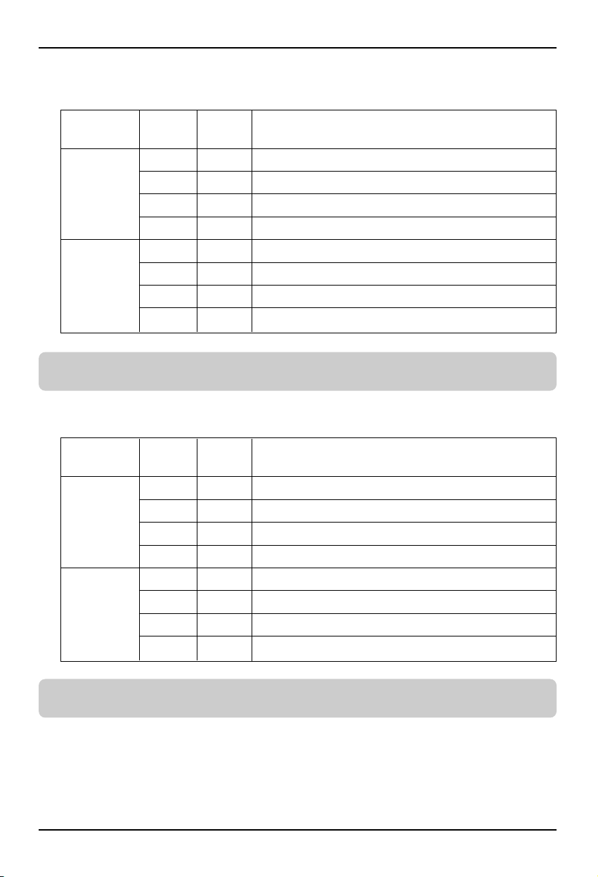
3) Fan level setting mode
4) Power save mode
➲ When the indoor unit is operating in Dry contact for communication, the fan level can be changed by
other controller when the fan level is set to low level and the indoor is in unlocked condition.
➲ When setting 9, A mode, the TEMP_SETTING must always be set to ON.
➲ Power save mode: Adjust the set temperature to +3°C for cooling and -3°C for heating.
Input A Input B Operating mode
OFF OFF
ON OFF
OFF ON
ON ON
OFF OFF
ON OFF
OFF ON
ON ON
Indoor unit operating at low level, locked
Indoor unit operating at low level, unlocked
Indoor unit stopped, locked
Indoor unit stopped, locked
Indoor unit operating at low level, locked
Indoor unit operating at low level, unlocked
Indoor unit stopped, locked
Indoor unit prior operating condition maintained, unlocked
CONTROL_
MODE S/W
7
8
Input A Input B Operating mode
OFF OFF
ON OFF
OFF ON
ON ON
OFF OFF
ON OFF
OFF ON
ON ON
Indoor unit operating in power save mode, locked
Indoor unit operating in power save mode, unlocked
Indoor unit stopped, locked
Indoor unit operating not in power save mode, unlocked
Indoor unit operating in power save mode, locked
Indoor unit operating in power save mode, unlocked
Indoor unit stopped, locked
Indoor unit stopped, locked
CONTROL_
MODE S/W
9
A
Page 14
Setting and using method
14 Dry contact for communication
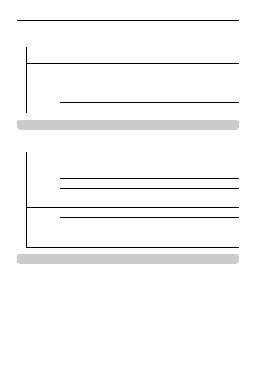
5) Compressor stop mode
➲ Compressor stop mode: The compressor is stopped during cool/heat operation.
6) Operating mode selection mode
➲ Power save mode: Adjust the set temperature to +3°C for cooling and -3°C for heating.
Input A Input B Operating mode
OFF OFF
ON OFF
OFF ON
ON ON
Indoor unit operating (Compressor in stop mode), locked
Indoor unit prior operating condition maintained
(Compressor not in stop mode), unlocked
Indoor unit stopped, locked
Indoor unit stopped, locked
CONTROL_
MODE S/W
B
Input A Input B Operating mode
OFF OFF
ON OFF
OFF ON
ON ON
OFF OFF
ON OFF
OFF ON
ON ON
Indoor unit stopped, unlocked
Indoor unit in cool/high operation, unlocked
Indoor unit in heat/high operation, unlocked
Indoor unit in fan/high operation, unlocked
Indoor unit stopped, locked
Indoor unit in cool/high operation, locked
Indoor unit in heat/high operation, locked
Indoor unit in fan/high operation, locked
CONTROL_
MODE S/W
C
D
Page 15
Setting and using method
Owner’s & installation manual 15
5. Indoor unit monitoring
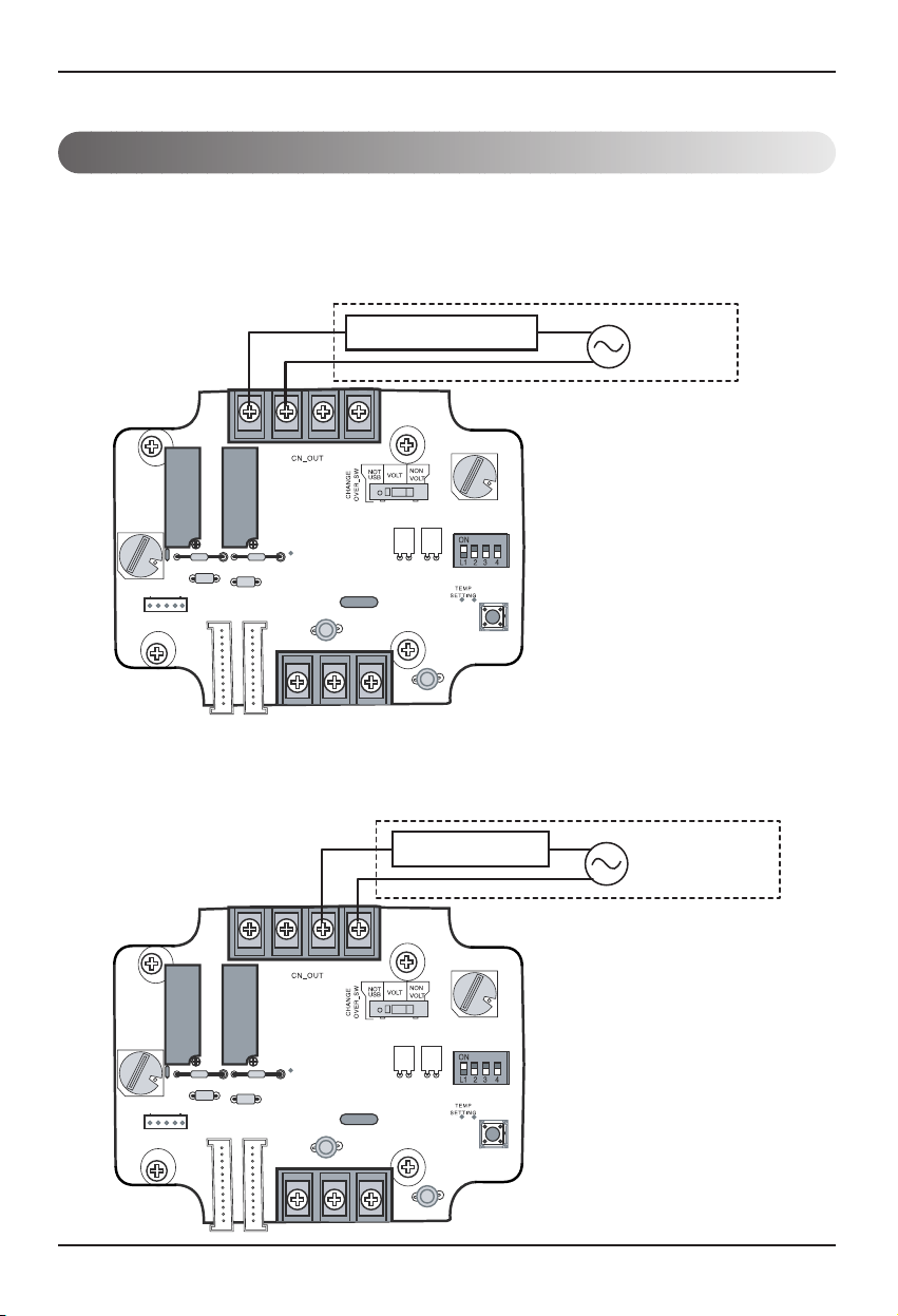
■ Monitoring whether the indoor unit is operating: Refer to
below and connect to the control device that you want to
control.
■ Monitoring indoor unit error: Refer to below and connect to
the control device that you want to control.
Operation Display
Error Display
Local Supply
(Depends on Operation
display power type)
Power
AC or DC
Local Supply
(Depends on Error
display power type)
Power
AC or DC
Page 16

P/No.: MFL42540202
After reading this manual, keep it in a place easily accessible to the user for future reference.
Printed in Korea
 Loading...