

Page 1

ENGLISH ITALIANO ESPAÑOL
FRANCAIS
DEUTSCH
PORTUGUESE
РУССКИЙ ЯЗЫК
P/NO : MFL32987304
INSTALLATION MANUAL
AIR
CONDITIONER
www.lg.com
TYPE :
MODELS : PRHR Series(Heat Recovery Unit)
Original instruction
Please read this installation manual completely before installing the product.
Installation work must be performed in accordance with the national wiring
standards by authorized personnel only.
Please retain this installation manual for future reference after reading it
thoroughly.
Page 2

2 HR Unit
PRHR Series Heat Recovery Unit Manual
TABLE OF CONTENTS
Safety Precautions .................................................................................................3
Features...................................................................................................................4
Installation Part.......................................................................................................4
Installation...............................................................................................................5
Coil Exchanging Method......................................................................................13
Page 3

Installation Manual 3
ENGLISH
Safety Precautions
Safety Precautions
To prevent injury to the user or other people and property damage, the following instructions must be followed.
n Incorrect operation due to ignoring instruction will cause harm or damage. The seriousness is classified by
the following indications.
This symbol indicates the possibility of death or serious injury.
This symbol indicates the possibility of injury or damage to properties only.
Have all electric work done by a licensed electrician according
to "Electric Facility Engineering Standard" and "Interior Wire
Regulations" and the instructions given in this manual and
always use a special circuit.
• If the power source capacity is inadequate or electric work is performed improperly, electric shock or fire may result.
Ask the dealer or an authorized technician to install the HR
unit.
• Improper installation by the user may result in water leakage, electric shock, or fire.
Always ground the product.
• There is risk of fire or electric shock.
Make the connections securely so that the outside force of the
cable may not be applied to the terminals.
• Inadequate connection and fastening may generate heat and
cause a fire.
For re-installation of the installed product, always contact a
dealer or an Authorized Service Center.
• There is risk of fire, electric shock, explosion, or injury.
Do not install, remove, or re-install the unit by yourself (customer).
• There is risk of fire, electric shock, explosion, or injury.
Do not damage or use an unspecified power cord.
• There is risk of fire, electric shock, explosion, or injury.
Do not touch the power switch with wet hands.
• There is risk of fire, electric shock, explosion, or injury.
Avoid a place where rain may enter since the HR unit is
for indoor.
• There is risk of property damage, failure of product, or electric shock.
Install the HR unit at a place in which it is not affected
by operation mode changing noise.
• Installation within cell such as meeting room etc. may disturb business due to noise.
Always check for gas (refrigerant) leakage after installation or repair of product.
• Low refrigerant levels may cause failure of product.
Keep level even when installing the product.
•
To avoid vibration or water leakage.
Securely install the cover of control box and the panel.
• If the cover and panel are not installed securely, dust or water may
enter the HR unit and fire or electric shock may result.
Be cautious when unpacking and installing the product.
• Sharp edges could cause injury. Be especially careful of the case
edges.
Safely dispose of the packing materials.
• Packing materials, such as nails and other metal or wooden parts, may cause stabs or other injuries.
• Tear apart and throw away plastic packaging bags so that children may not play with them. If children play with a plastic bag which was
not torn apart, they face the risk of suffocation.
Do not store or use flammable gas or combustibles near the
HR Unit.
• There is risk of fire or failure of product.
Use the correctly rated breaker or fuse.
• There is risk of fire or electric shock.
Page 4

4 HR Unit
Features & Installation Part
Installation Part
• Installation Manual
• Hanging bolts (4 x M10 or M8, Nut(8 x M10 or M8), Flat washers(8 x M10)
• Reducers
Features
Control Box
Connection Pipe
(to outdoor unit)
Connection Pipe
(to outdoor unit)
Coil assembly, Solenoid
Connection Pipe
(to indoor unit)
Model
Max. Connectable No. of Indoor Units
Max. Connectable No. of Indoor Units of a branch
Nominal Input Cooling
Heating
Net. Weight kg
lbs
Dimensions mm
(WxHxD) Inch
Casing
Connecting Pipes Indoor Liquid Pipe [mm/inch]
side Gas Pipe [mm/inch]
Outdoor Liquid [mm/inch]
side Low Pressure [mm/inch]
High Pressure [mm/inch]
Sound Absorbing Insulation Material
Current Minimum circuit Amps(MCA)
Maximum fuse Amps(MFA)
Power Supply
PRHR021 PRHR031 PRHR041
16 24 32
8 8 8
26 40 40
26 40 40
18 20 22
39.7 44.1 48.5
801x218x617 801x218x617 801x218x617
31.5x8.6x24.3 31.5x8.6x24.3 31.5x8.6x24.3
Galvanized steel plate
Ø9.52[3/8] Ø12.7[1/2] Ø15.88[5/8]
Ø22.2[7/8] Ø28.58[1-1/8] Ø28.58[1-1/8]
Ø19.05[3/4] Ø22.2[7/8] Ø22.2[7/8]
1Ø, 220-240V, 50Hz / 1Ø, 220V, 60Hz
Ø9.52[3/8]
Ø15.88[5/8]
Polyethylene Foam
Models
Indoor unit
reducer
PRHR021
Liquid pipe
Ø6.35OD9.52
Ø6.35OD9.52
High pressure
OD19.05 Ø15.88 Ø12.7
0.2
15
Gas pipe
Low pressure
OD15.88 Ø
12.7
OD22.2 Ø19.05 Ø15.88
HR unit
reducer
PRHR031/
PRHR041
OD15.88 Ø12.7 Ø9.52
OD12.7 Ø9.52
OD22.2 Ø19.05 Ø15.88
OD15.88 Ø12.7
OD15.88 Ø12.7
OD28.58 Ø22.2 Ø19.05
OD19.05 Ø15.88
Page 5

Installation Manual 5
ENGLISH
Installation
Installation
n Select installation location of the HR unit suitable for following conditions
• Avoid a place where rain may enter since the HR unit is for indoor.
• Sufficient service space must be obtained.
• Refrigerant pipe must not exceed limited length.
• Avoid a place subject to a strong radiation heat from other heat source.
• Avoid a place where oil spattering, vapor spray or high frequency electric noise is expected.
• Install the unit at a place in which it is not affected by operation noise. (Installation within cell such as meeting
room etc. may disturb business due to noise.)
• Place where refrigerant piping, drain piping and electrical wiring works are easy.
NOTES
* Be sure to install the inspection door at the electric control side.
** If reducers are used, servicing space must be increased equal to reducer's dimension.
Selection of the best location
Dimensional drawings
100 more
(Servicing space)
100 more
(Servicing space)
(Unit: mm)
No. Part Name
Description
PRHR041/031 PRHR021
1 Low pressure Gas pipe connection port Ø28.58 Brazing connection Ø22.2 Brazing connection
2 High pressure Gas pipe connection port Ø22.2 Brazing connection Ø19.05 Brazing connection
3 Liquid pipe connection port
Ø15.88 Brazing connection(PRHR041)
Ø12.7 Brazing connection(PRHR031)
Ø9.52 Brazing connection
4 Indoor unit Gas pipe connection port Ø15.88 Brazing connection Ø15.88 Brazing connection
5 Indoor unit Liquid pipe connection port Ø9.52 Brazing connection Ø9.52 Brazing connection
6 Control box
7 Suspension bolts M10 or M8 M10 or M8
481
450
450
7
345
1
2
3
(*) Inspection door
(servicing space)
300 more
(**)(Servicing space)
300 more
(**)(Servicing space)
100 more
100 more
(Servicing space)
(Servicing space)
300 more
(**)(Servicing space)
100 more
100 more
(Servicing space)
(Servicing space)
450 more
(Servicing space)
218
453(174)
(174)
124
182
182
6
41961 (137)
4 5
60
30
Page 6
6 HR Unit
Installation
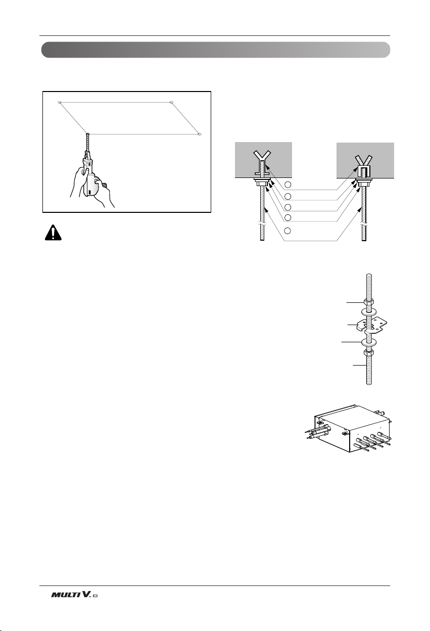
• Select and mark the position for fixing bolts.
• Drill the hole for set anchor on the face of ceiling.
• Insert the set anchor and washer onto the suspension bolts for locking the suspension bolts on the
ceiling.
•
Mount the suspension bolts to the set anchor firmly.
• Secure the installation plates onto the suspension
bolts (adjust level roughly) using nuts, washers
and spring washers.
1 Set anchor
Old building New building
2 Plate washer
3 Spring washer
4 Nut
5 Suspension
bolts
HR Unit Installation
CAUTION : Tighten the nut and bolt
to prevent unit falling.
Hanger metal
Flat washer
1. Using an insert-hole-in- anchor, hang the suspension bolt.
2. Install a hexagon nut and a flat washer (locally-procured)to the suspension bolt as
shown in the figure in the bottom, and fit the main unit to hang on the hanger metal.
3. After checking with a level that the unit is level, tighten the hexagon nut.
* The tilt of the unit should be within ±5° in front/back and left/right.
4. This unit should be installed suspended from ceiling and side A should always be
facing up.
Six-sided Nut
(M10 or M8)
Hanger metal
Hanger metal
Flat washer
Flat washer
(M10)
Suspension bolt
(M10 or M8)
A
Page 7
Installation Manual 7
ENGLISH
Installation
CAUTION:
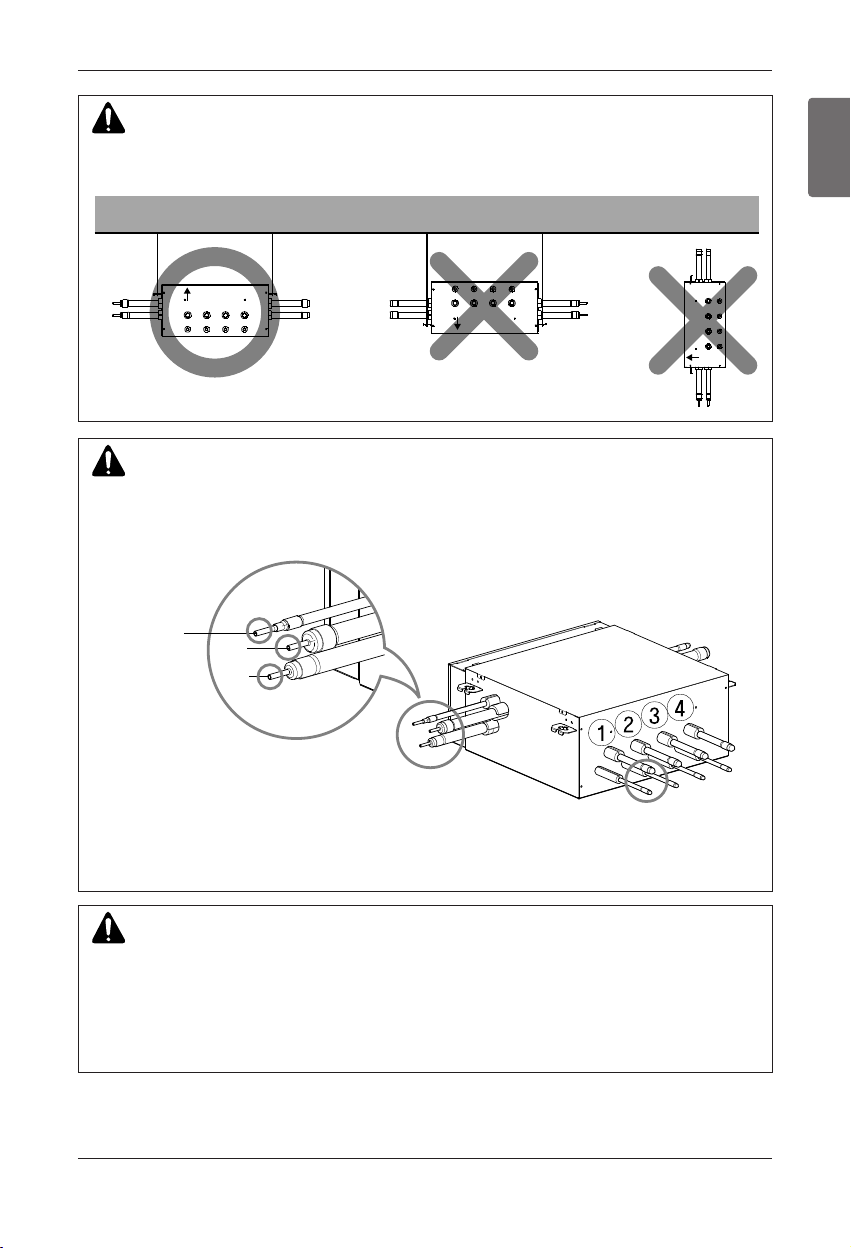
HR Unit should be installed that top side is facing up. If not, it may cause failure of the product.
WARNING:
Before brazing work, remove gas in the HR Unit by cutting the three pipes in the small circles on the figure.
If not, it may cause injuries.
Remove the caps before connecting pipes.
Liquid pipe
Low pressure gas pipe
High pressure gas pipe
CAUTION:
• Whenever connecting the indoor units with the HR unit, install the indoor units in numerical order
from No.1.
Ex) In case of installing 3 indoor units : No. 1, 2, 3 (O), No. 1, 2, 4 (X), No.1, 3, 4 (X), No.2, 3, 4 (X).
• Take care of no thermal damage on the valves of the HR uint.
(Especially packing part of valve) Wrap the valve with a wet towel when brazing it.
Ceiling
Top side
Top side
Top side
Liquid pipe
Liquid pipe
Low pressure gas pipe
Low pressure gas pipe
High pressure gas pipe
High pressure gas pipe
(Brazing Type)
Gas pipe Ø15.88
Liquid pipe Ø9.52
Brazing Type
Page 8
8 HR Unit
Installation
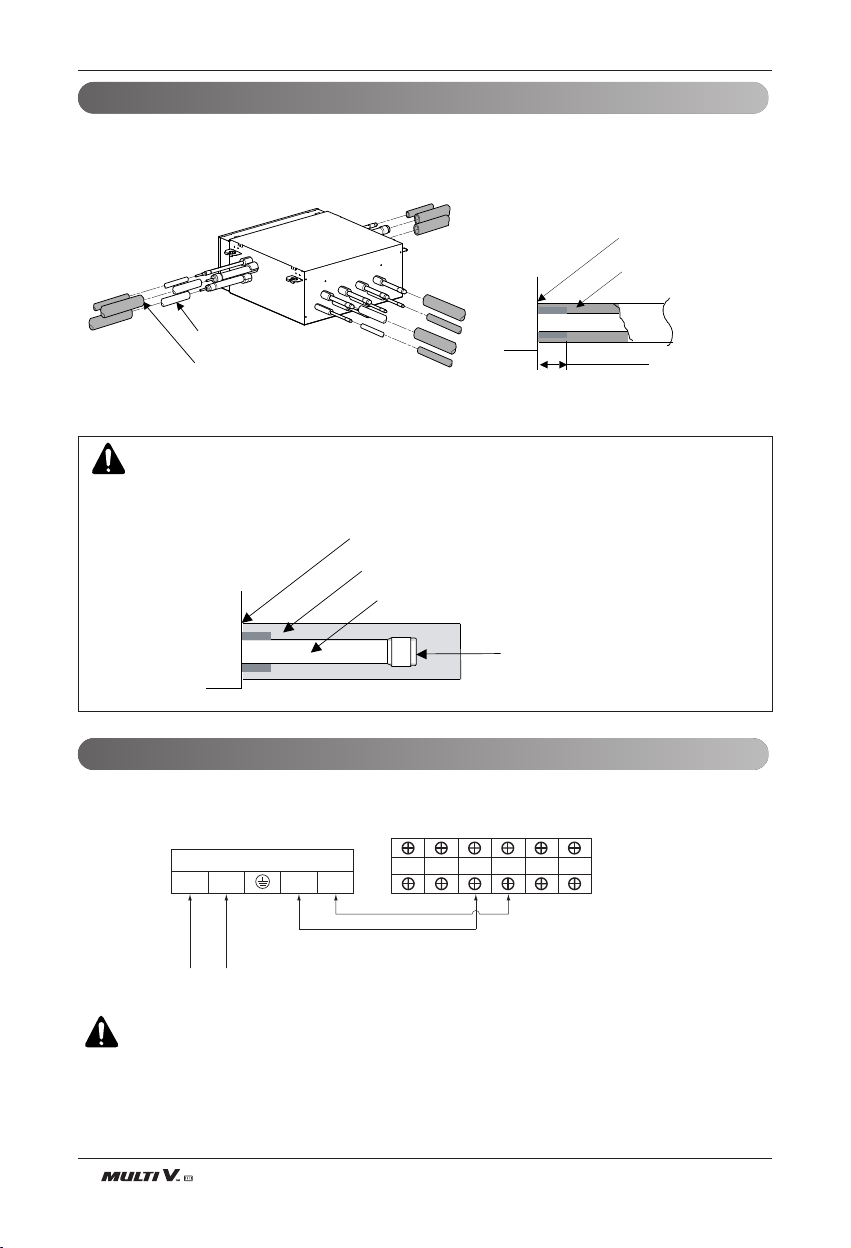
Insulate the connected pipes completely(all thermal insulation must comply with local requirement)
Thermal Insulation
Wiring Connection
CAUTION:
Insulate completely unconnected pipes as shown in the Figure.
Not connected pipe
Always seal up the
tip of unused pipe by brazing
Thermal insulator for
refrigerant pipe(Local supply)
Make sure that there is no
clearance here
Connect the wires to the terminals on the control board individually according to the outdoor unit connection.
• Ensure that the color of the wires of outdoor unit and the terminal No. are the same as those of HR Unit respectively.
WARNING : Make sure that the screws of the terminal are free from looseness.
Wiring Connection
Make sure that there is no
clearance here
Thermal insulator for
refrigerant pipe(Local supply)
Refrigerant pipe
(Local supply)
Thermal insulator for refrigerant pipe
(Local supply)
Overlap with thermal
insulator for piping
Terminal Block HR Unit
1(L) 2(N) 3 4
HR UNIT POWER INPUT
SODU B SODU A IDU B IDU A INT B INT A
Master
Outdoor Unit
Page 9
Installation Manual 9
ENGLISH
Installation
Setup the switch of HR Unit
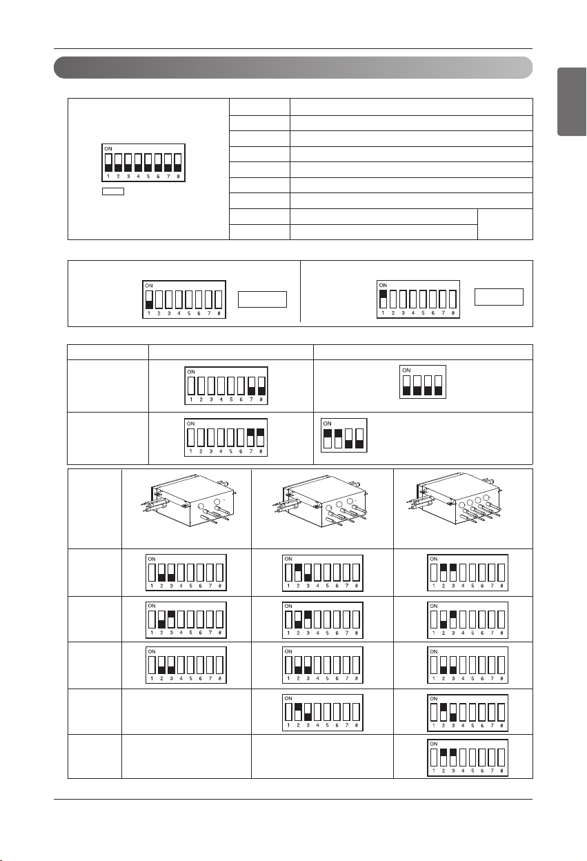
1. Main function of SW02M
ON S/W Selection
No.1
Method for addressing valves of an HR unit (Auto/Manual)
No.2 Model of HR unit
No.3 Model of HR unit
No.4 Model of HR unit
No.5 Valve group setting
No.6 Valve group setting
No.7
Use only in factory production (preset to “OFF”)
No.8
Use only in factory production (preset to “OFF”)
SW02M
1) Selection of the method for addressing valves of an HR unit (Auto/Manual)
Auto
Manual
Switch No.1 OnSwitch No.1 Off
h Each model is shipped with the switches No.2 and No.3 pre-adjusted as above in the factory.
Zoning setting
("ON")
1
2
3
1
2
1
3
2
4
(For 2 branches)
PRHR021A
(For 3 branches)
PRHR031A
(For 4 branches)
PRHR041A
Initial
Setting
1 branch
Connected
2 branches
Connected
3 branches
Connected
4 branches
Connected
2) Setting the zoning control
DIP S/W setting
Normal
control
SW01M
Zoning
control
SW01M
Turn the dip switch of the zoning
branch on.
EX) Branch 1,2 are zoning control.
Page 10
10 HR Unit
Installation
WARNING
• If you want to use a PRHR031 for 2 branches HR unit after closing the 3rd pipes, set the dip switch for 2 branches HR unit.
• If you want to use a PRHR041 for 3 branches HR unit after closing the 4th pipes, set the dip switch for 3 branches HR unit.
• If you want to use a PRHR041 for 2 branches HR unit after closing the 3rd and 4th pipes, set the dip switch for 2 branches HR
unit.
• The unused port must be closed with a copper cap, not with a plastic cap.
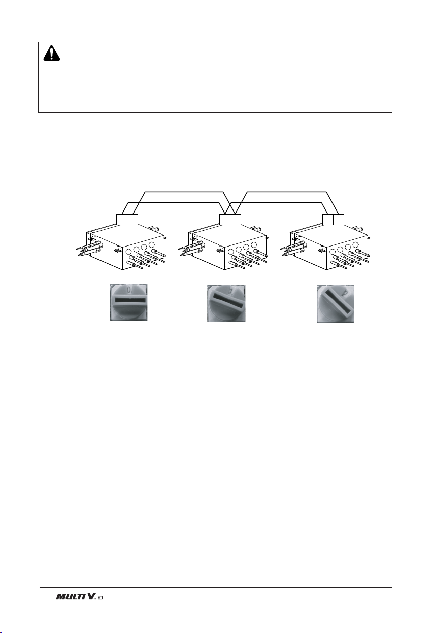
2. SW05M (Rotary S/W for addressing HR unit)
Must be set to '0' when installing only one HR unit.
When installing multiple HR units, address the HR units with sequentially increasing numbers starting from '0'.
Maximum 16 HR Units can be installed.
Ex) Installation of 3 HR units
34 34 3 4
4
3
2
1
4
3
2
1
4
3
2
1
Page 11
Installation Manual 11
ENGLISH
Installation
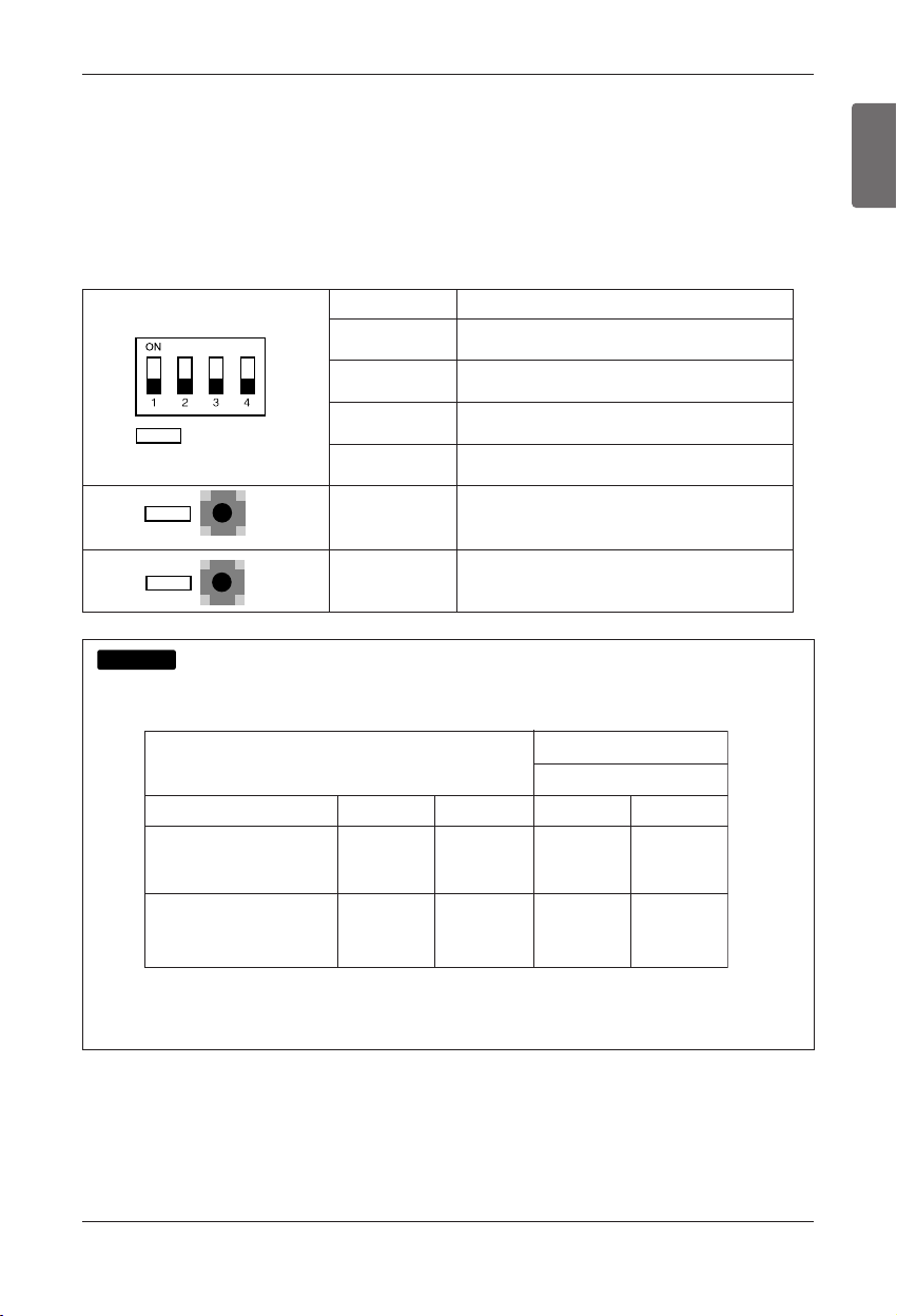
3. SW01M/SW03M/SW04M (Dip S/W and tact S/W for manual valve addressing)
1) Normal setting (Non-Zoning setting)
- Used in manual addressing of the valve in the HR unit
- Set the address of the valve of the HR unit to the central control address of the connected indoor unit.
- SW01M: selection of the valve to address
SW03M: increase in the digit of 10 of valve address
SW04M: increase in the last digit of valve address
- Prerequisite for manual valve addressing : central control address of each indoor unit must be preset differ-
ently at its wired remote control.
S/W No. Setup
No.1 Manual addressing of valve #1
No.2 Manual addressing of valve #2
No.3 Manual addressing of valve #3
No.4 Manual addressing of valve #4
SW03M Increase in the digit of 10 of valve address
SW04M Increase in the last digit of valve address
SW01M
SW03M
SW04M
Write positions of indoor units connected with each port and Central address, also write rotary S/W number
of HR Unit like below example.
If the branch 4 is not connected with an indoor unit, don't write on blank of table.
NOTICE
Rotary S/W number
HR Unit ( Multi V Sync )
Number of branch
Position of
indoor unit
Central address
of indoor unit
( In case of manual addressing of
valves )
Lecture
Room 1
Dormitory
Room 2
Conference
Room 1
0
4321
X
060504
X
Page 12
12 HR Unit
Installation
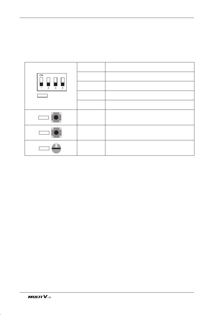
2) Zoning setting
- Set the address of the valve of the HR unit to the central control address of the connected indoor unit.
- SW01M : selection of the valve to address
SW03M : increase in the digit of 10 of valve address
SW04M : increase in the last digit of valve address
SW05M :Rotary S/W
- Prerequisite for manual valve addressing : central control address of each indoor unit must be preset
differently at its wired remote control.
S/W No. Setup
No.1 Manual addressing of valve #1
No.2 Manual addressing of valve #2
No.3 Manual addressing of valve #3
No.4 Manual addressing of valve #4
SW03M Increase in the digit of 10 of valve address
SW04M Increase in the last digit of valve address
SW05M Manual addressing of zoning indoor units
SW01M
SW03M
SW04M
SW05M
0
Page 13
Installation Manual 13
ENGLISH
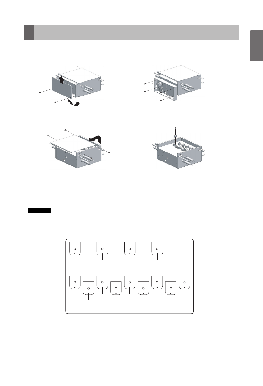
Coil Exchanging Method
Be sure that system power off before exchanging the coil.
Check the position of the solenoid coil with the label attached on the cover inside when abnormal noise is
heard loudly during operation.
Position label of the solenoid coil(PRHR041)
Coil Exchanging Method
NOTICE
1. Remove the 2 securing screws.
Remove the cover by pulling on the bottom of the
cover and lifting up.
3. Remove the 4 securing screws.
Lift up and pull on the cover.
NOTES
Refer to the label concerned the solenoid coil's position
attached on the cover inside.
2. Take out the connectors on the pcb.
Remove the 4 securing screws.
Lay down the control box.
4. Remove the securing nut with a spanner.
Exchange the coil.
Branch 4
Bypass
(CN11)
Branch 4
Low
(CN07)
Branch 4
High
(CN07)
Branch 3
Bypass
(CN10)
Branch 3
Low
(CN06)
Branch 3
High
(CN06)
Branch 2
Bypass
(CN09)
Branch 2
Low
(CN05)
Branch 2
High
(CN05)
Branch 1
Bypass
(CN08)
Branch 1
Low
(CN04)
Branch 1
High
(CN04)
Bypass
(CN12)
Page 14

14 HR Unit
Page 15

[
Representative
] LG Electronics Inc. EU Representative
Krijgsman 1, 1186 DM Amstelveen, The Netherlands
[Manufacturer]
LG Electronics Inc. Changwon 2nd factory
84, Wanam-ro, Seongsan-gu, Changwon-si, Gyeongsangnam-do, KOREA
 Loading...