

LG PQDSBCDVM0 INSTALLATION MANUAL
P/NO : MFL42540239
INSTALLATION MANUAL
TYPE : (Dry contact for demand control)
MODELS : PQDSBCDVM0
AIR
CONDITIONER
www.lg.com
Please read this installation manual completely before installing the product.
Installation work must be performed in accordance with the national wiring
standards by authorized personnel only.
Please retain this installation manual for future reference after reading it thoroughly.
ENGLISH
ITALIANO
ESPAÑOL
FRANÇAIS
DEUTSCH
ΕΛΛΗΝΙΚΆ
ČEŠTINA
NEDERLANDS
POLSKI
LIMBA ROMÂNĂ
PORTUGUESE
MAGYAR
БЪЛГАРСKN
SRPSKI
HRVATSKI
SVENDKA
NORSK
SUOMI
DANSK
EESTI KEEL
MALTI
SLOVENČINA
SLOVENŠČINA
LATVIEŠU VALODA
LIETUVIŲ KALBA
GAEILGE
МАКЕДОНСКИ
SHQIP
ÍSLENSKA BOSANSKI
2
SAFETY PRECAUTIONS
ENGLISH
SAFETY PRECAUTIONS
To prevent injury to the user or other people
and property damage, the following instructions must be followed.
•
Incorrect operation due to ignoring instruction
will cause harm or damage. The seriousness
is classified by the following indications.
WARNING
This symbol indicates the possibility of death
or serious injury.
CAUTION
This symbol indicates the possibility of injury
or damage.
• Meanings of symbols used in this manual
are as shown below.
WARNING
During installation
• Do not touch the board when the power is
connected.
• Always request for installation of the prod-
uct to the service center or the installation
service provider.
• When reinstalling the previously installed
product, request for service to the service
center or the installation service provider.
• Do not install the product where it can be
exposed to rain.
•
Do not install the product in a humid location.
During use
• Do not modify or extend the power cord.
•
Do not use any flaming devices near the product.
• Do not use any heating devices near the
power cord.
• Do not pour water inside the product.
• When the product is submersed in water,
always request for service to the service center or the installation service provider.
• Make the children and the elderly use the
product with the help a guardian.
• Do not give impact to the product.
* Install and use by qualified personnel only.
!
!
!
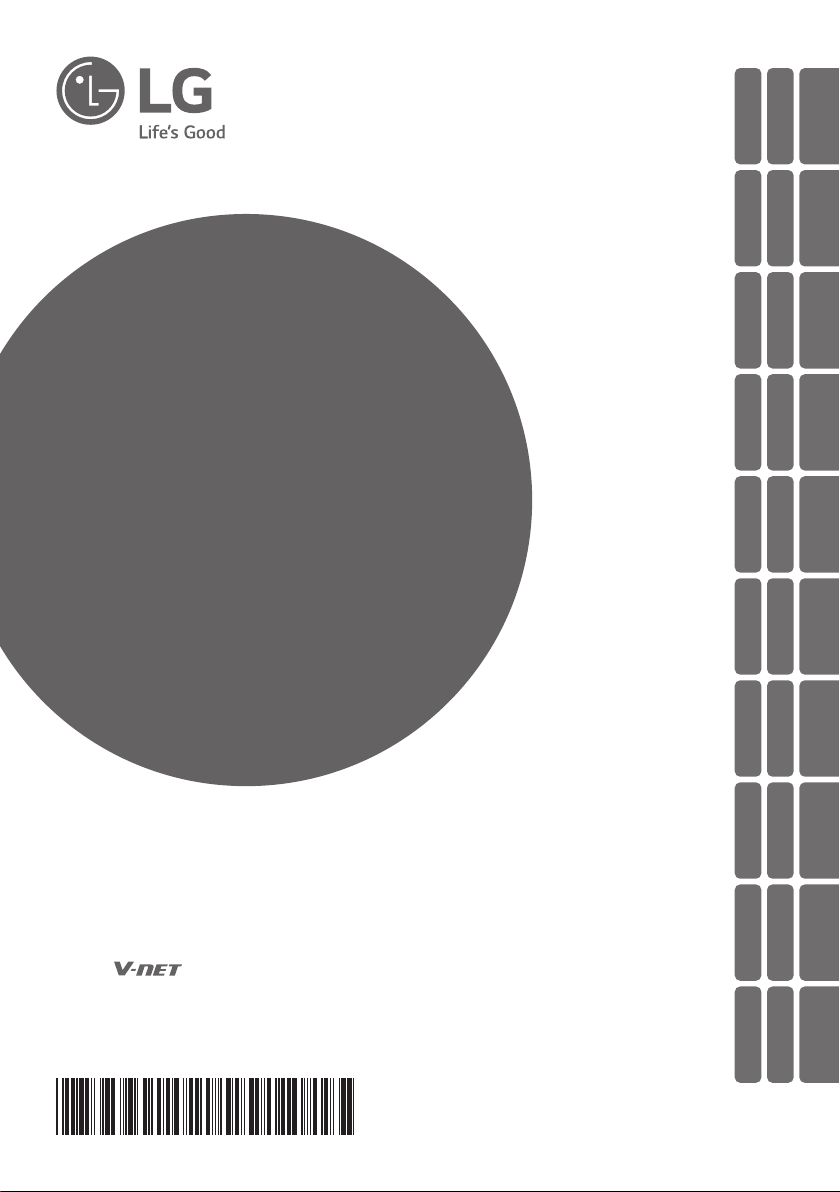
Dry contact for DEMAND CONTROL
1. SWDIP : Switch to select main function
2. SW_Address2 : Switch to set a upper
address of the outdoor unit
3. SW_Address1 : Switch to set a lower
address of the outdoor unit
4. SW_STEP : Switch to select a control
mode.
5. CN_PWR : DC Input terminal
6. ERROR : Error display with relay contact
7. BUS-A : RS-485 (+) Terminal
8. BUS-B : RS-485 (-) Terminal
9. CN_CAPACITY : Signal input terminal to
control a capacity of outdoor unit
10. CN_SPEED/CAP : Signal input terminal for
Analog Input/Low noise operation
11. CN_OUT : Outdoor unit connector
12. LED1 : Display LED for RS-485 status
13. LED01G,02G,03G : Display LED for com-
munication status
14. CN_JIG : Connector for writing program
15. SW1 : Reset switch
NAME OF EACH PART
12 34 5
15
14
13
12
91011
6
7
8
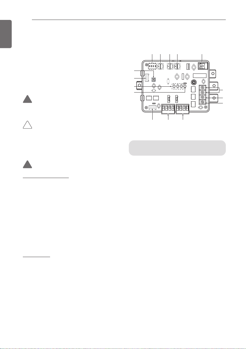
ACCESSORY PARTS
3
ENGLISH
INSTALLATION
METHOD
1. Connect the connection wires according to
the instructions.
(Please refer to Setting and Using Method)
2. Perform the switch setting according to
switch setting method.
(Please refer to Setting and Using Method)
3. Fix the Dry contact on suitable space inside
of the outdoor unit.
SETTING AND USING
METHOD
After change any Dry contact setting, then
you must press RESET switch to reflect the
setting.
Power source input
① When wiring power source from outdoor
unit.
② When using external power source.
System structure
When outdoor unit has RS-485
communication function
(Master Mode)
NOTE
!
This device can accept only DC Power
input.
Do not input 220VAC. Otherwise It will
cause a serious damage.
Install the product on flat surface and
screw at least 2 places. Otherwise the Dry
contact may not be anchored properly.
Do not screw too tightly. It may cause deformation of the case.
Do not deform the case at random. It may
cause malfunction of the Dry contact.
CAUTION
!
① DC12V or DC15V
② DC12V
① GND Outdoor Unit
PCB
② GND Power
Source
ACCESSORY PARTS
Others : Tie Wrap (3 EA) - Cable Tie
Clamp (1 EA)
RS-485
BUS_B
BUS_A
Multi-V
ODU Dry contact
PQDSBCDVM0
Sub cable
WIRE ASSY 2(1EA)
BRACKET (1EA)
Multi-V
WIRE ASSY 1(1EA)SCREW (4EA)
 Loading...