How it Works
Log In / Sign Up
Buy Points
How it Works
FAQ
Contact Us
Questions and Suggestions
Users
LG
Loading...
P
PM01122-A
PM05SP
PM07SP
PM09EP
2
PM09SP
2
PM1
5
PM12EP
PM12SP
7
PM18SP
PM19BA
PM20GA
PM225
4
PM5
4
PM7
4
PM9700
PM97-Z
PMBD3620
4
PMBD3630
3
PMBD3640
PMBUSB00A
3
PMC-1000
2
PMC-610
PMNFP14A0
5
PMNFP14A1
11
PMUB1111A
PMUB11A
PN1
17
PN5
15
PN-53A80P
PN7
14
PNEL-T707A
PNELT708A
PNF220G
PNF223G
PNF223GL
PNF228G
PNF231G
PN-F60B
PN-F60P
POCKET PHOTO PD251
POD200
Power 2
2
PP-43A80P
2
PP485B00K
4
PP-48A80P
3
PP-53A80P
2
PPWRDB000
9
PQCPA11A0E
3
PQCPB11A0E
2
PQCPC22A0
3
PQCPC22N0
PQCSB101S0
12
PQCSC101S0
5
PQCSD130A0
7
PQCSE341A0
3
PQCSE342A0
2
PQCSE440U0
4
PQCSS520A0E
2
PQCSSA21E0
3
PQCSW320A0E
PQCSW320A1E
4
PQCSW421E0A
7
PQCSZ250S0
11
PQDSA
PQDSB
3
PQDSB1
PQDSBC
PQDSBCDVM0
2
PQDSBCGCD0
2
PQNFB16A0
PQNFB16A1
PQNFB17B0
PQNFB17C0
7
PQNFG14B0
2
PQNFP00T0
3
PQNUD1S00
8
PQNUD1S40
10
PQNUD1S41
PQRCFCS0
4
PQRCFCS0C
5
PQRCHCA0Q
4
PQRCHCA0QW
7
PQRCUCA0
PQRCUCS0C
5
PQRCUDS0
3
PQRCUDS0B
4
PQRCUDS0S
PQRCUSA0
2
PQRCVCL0Q
PQRCVCL0QW
7
PQRCVSL0
3
PQRCVSL0QW
4
PQRNC0
PQRSTA0
3
PQ Series
PQWRCDF0
5
PQWRCQ0FDB
2
PQWRCSF0
5
PQWRHDF0
5
PQWRHQ0FDB
9
Loading...
Loading...
Nothing found
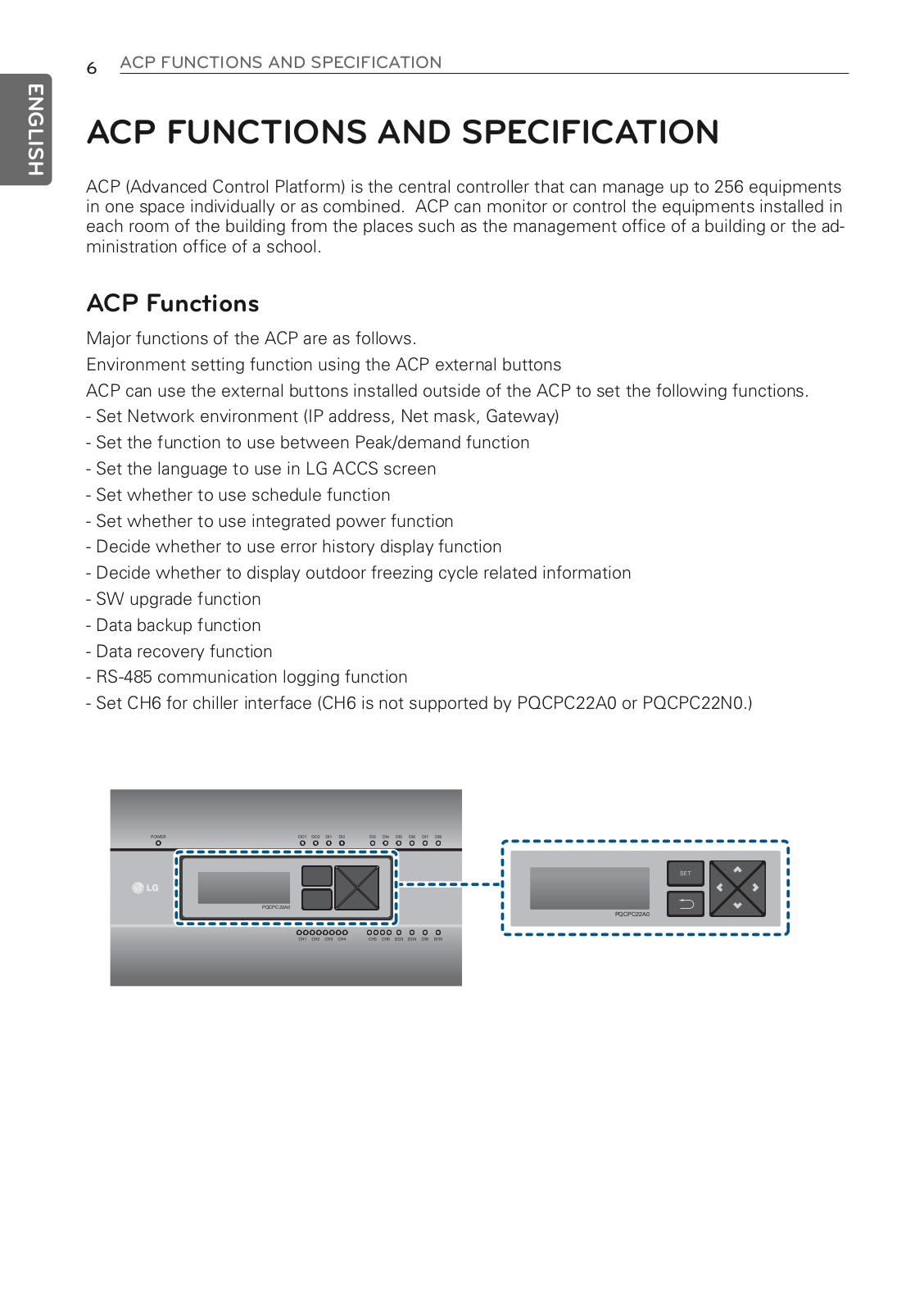
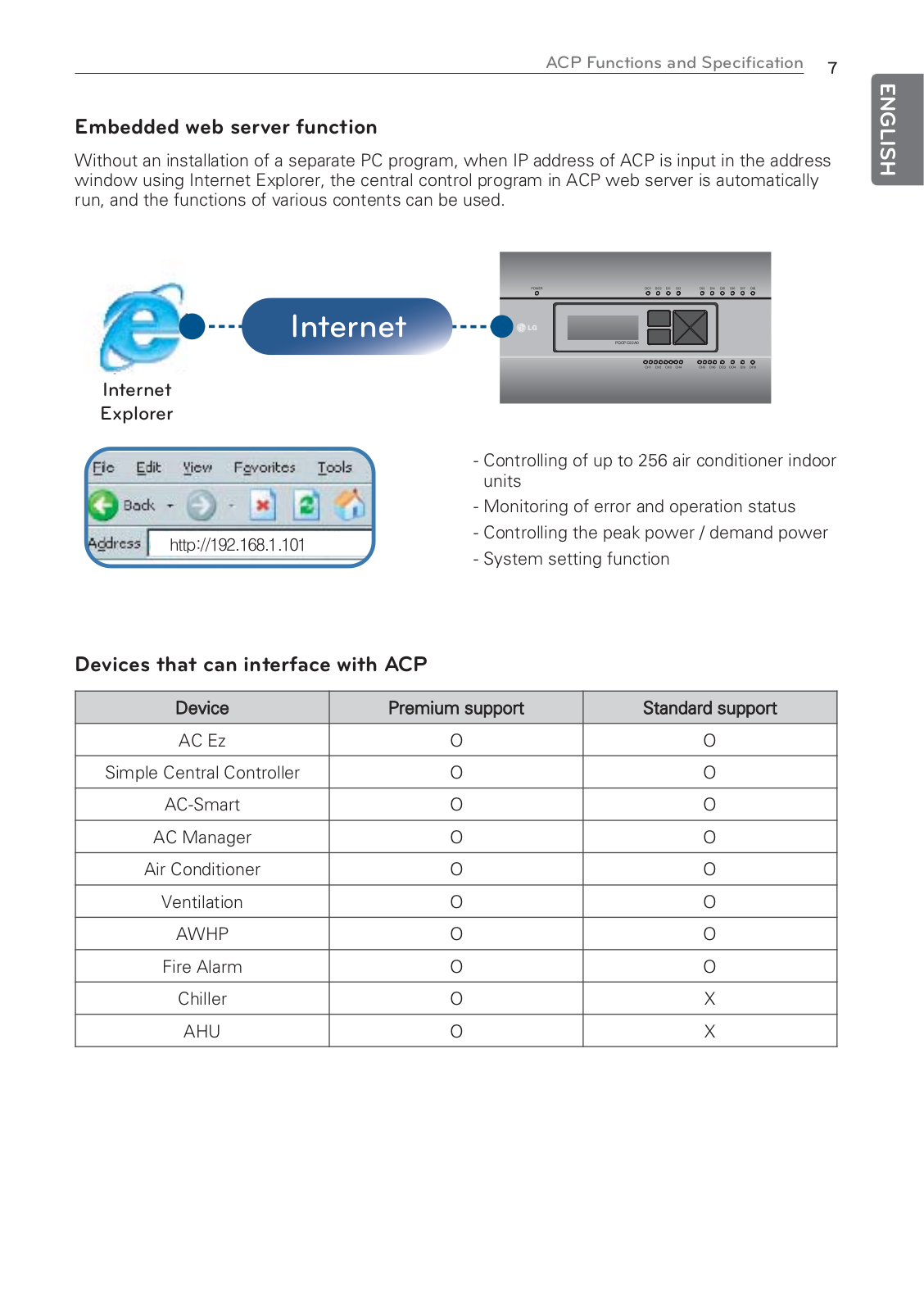
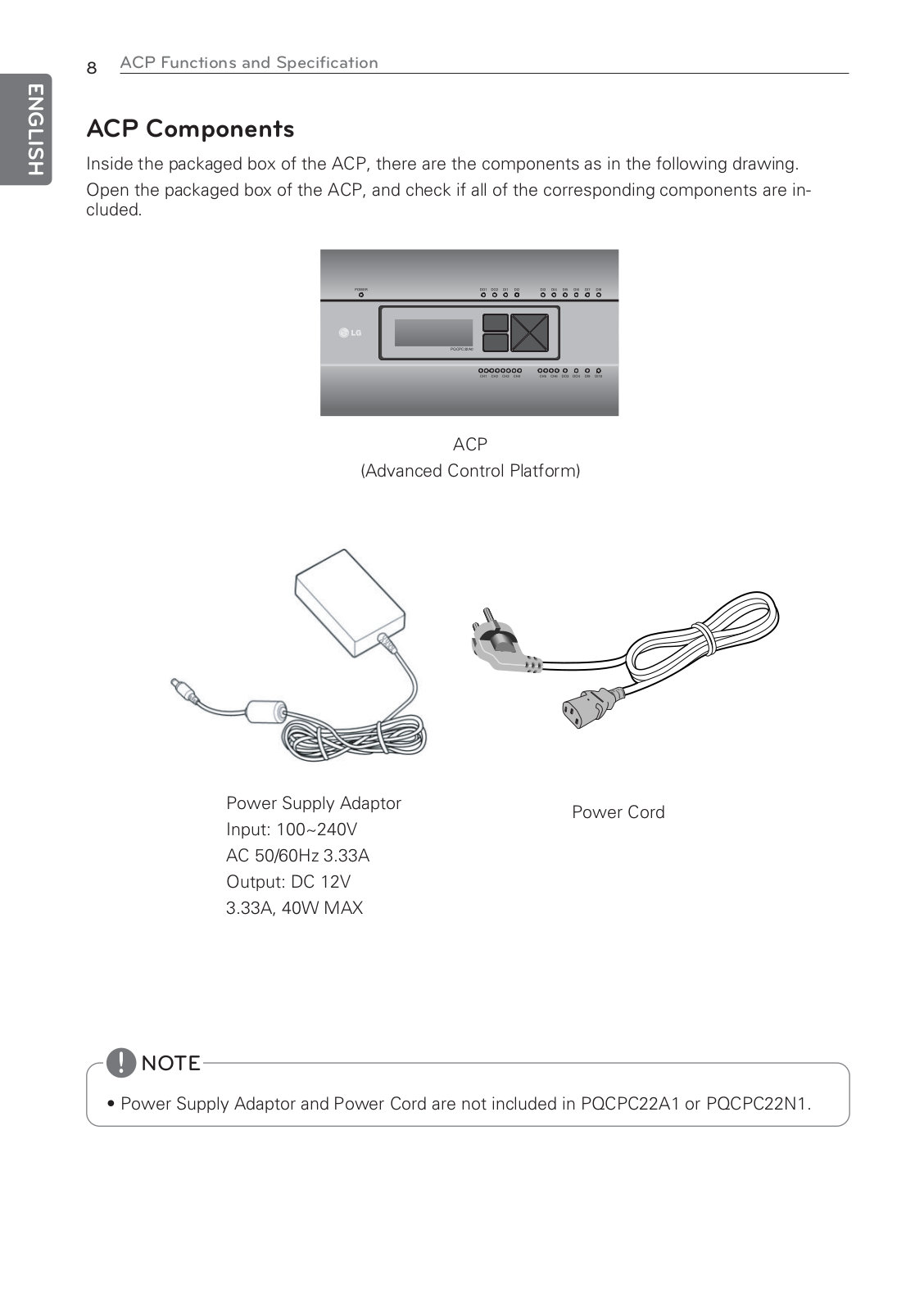
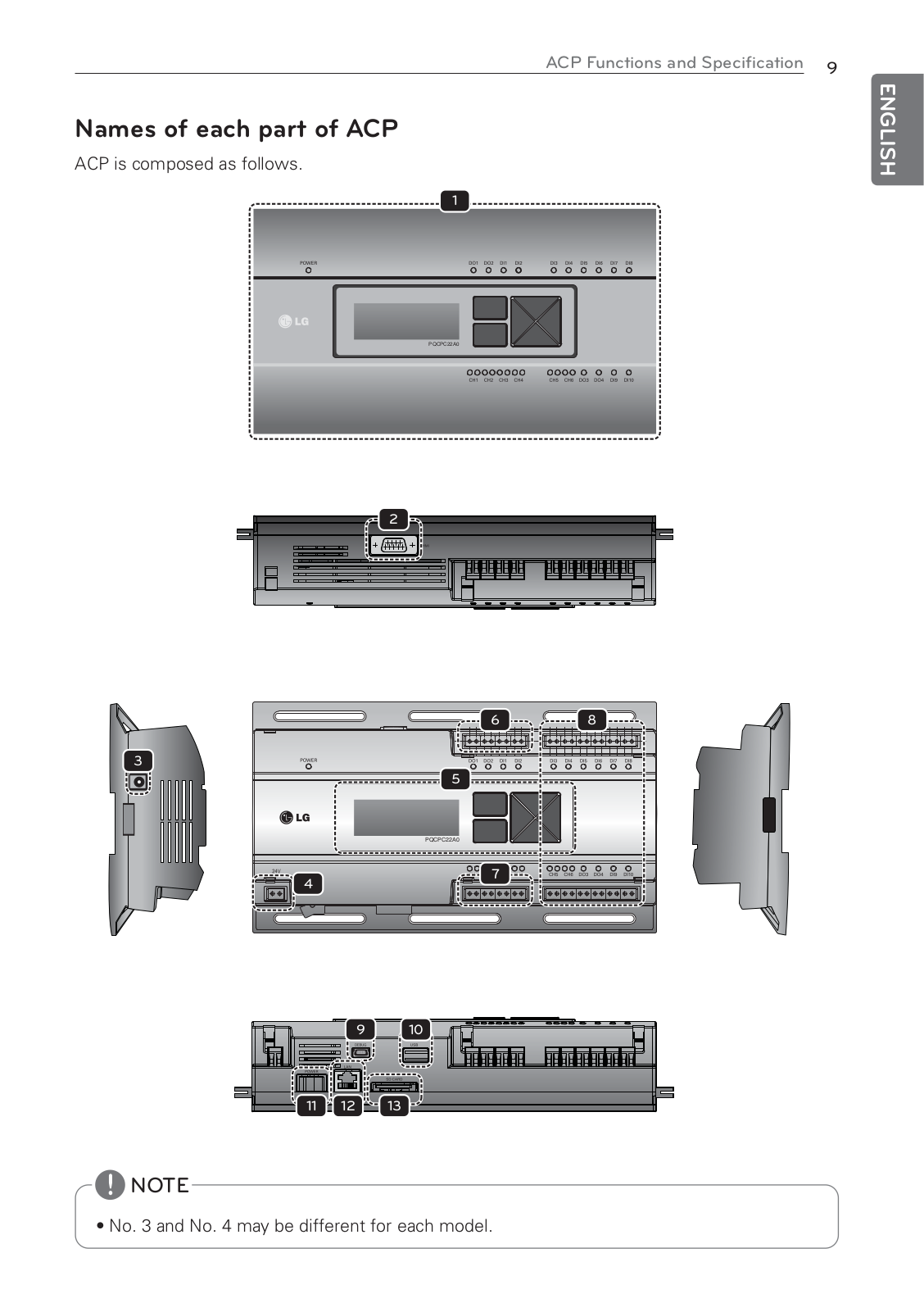
PQCPC22A0
Owner’s Manual [fr]
125 pgs
5.72 Mb
0
User guide
125 pgs
5.72 Mb
0
User guide [ru]
125 pgs
5.85 Mb
0
Table of contents
Loading...
LG PQCPC22A0 User guide
...
LG User guide
Download
Specifications and Main Features
Frequently Asked Questions
User Manual
Download
Loading...
+
95
hidden pages
Unhide
You need points to download manuals.
1 point = 1 manual.
You can buy points or you can get point for every manual you upload.
Buy points
Upload your manuals
 Loading...