

LG PQCPA11A0E User guide

ACP
Advanced Control Platform
(PQCPA11A0E, PQCPB11A0E)
Installation/Owner's Manual
LG
Caution
• Read this manual thoroughly before installing the product.
• Only the certified professional should install this product.
• Keep this manual for referring during the operation later.

2
ACP
Advanced Control Platform
Contents
1. ACP FUNCTIONS & SPECIFICATION .............1-1
Functions of ACP ............................................................................................................1-1
Denomination of ACP .....................................................................................................1-4
Components of ACP .......................................................................................................1-6
Hardware specification of ACP......................................................................................1-7
2. INSTALLING ACP.............................................2-1
Before installing the ACP ...............................................................................................2-2
• Using the single ACP as web server ........................................................................2-3
• Connecting the single ACP to the AC Manager ......................................................2-5
• Connecting more than on ACPs to the AC Manager ..............................................2-7
Setting the indoor unit address .....................................................................................2-8
• Setting the address by the wired remote controller ...............................................2-9
• Setting the address by the wireless remote controller.........................................2-10
Setting the PI485 and Connecting the cable .............................................................2-12
• Setting the PI485 DIP switch ...................................................................................2-12
• Connecting the 2PIN connector..............................................................................2-14
• Connceting RS485 cable to PI485...........................................................................2-16
Installing the ACP and Connecting the cable.............................................................2-19
• Fixing the ACP at the installation site ....................................................................2-19
• Connecting RS485 cable to ACP ............................................................................2-20
• Connecting Ethernet cable to ACP.........................................................................2-23
• Connecting Power adaptor to ACP.........................................................................2-24
Configuring the ACP network ......................................................................................2-25
• Before configuring the ACP environment..............................................................2-25
• Setting the IP address..............................................................................................2-29
• Setting the gateway address...................................................................................2-30
• Setting the net mask address .................................................................................2-31
• Checking the network environment .......................................................................2-32

Installation/Owner's Manual
3
3.
ACP OPERATION BY USING THE LG ACCS
.............3-1
Setting the functions of the ACP .................................................................................2-33
• Before setting the functions of the ACP ................................................................2-33
• Selecting Peak or Demand ......................................................................................2-34
• Selecting the ACCS display language....................................................................2-36
• Setting whether to use the schedule function or not ...........................................2-38
• Setting whether to use the wattage display function or not ................................2-40
• Setting error history display ..................................................................................2-42
Configuring the ACCS access .....................................................................................2-43
• Chceking the MS JAVA VM installation .................................................................2-43
• Checking the MS Explorer security setting ...........................................................2-45
Entering the indoor unit & ventilator information......................................................2-49
• If the ACP is connected to the AC Manager ..........................................................2-49
• If the ACP is not connected to the AC Manager....................................................2-50
Making sure and checking the ACP installation ........................................................2-67
Accessing the ACCS.......................................................................................................3-1
Reviewing the initial ACCS screen................................................................................3-4
Controlling the air conditioner.......................................................................................3-7
Controlling the ventilator .............................................................................................3-14
Setting the schedule .....................................................................................................3-21
• Reviewing the schedule setup screen ...................................................................3-21
• Example for setting the schedule ...........................................................................3-32
Controlling the peak operation rate ............................................................................3-44
Controlling the demand electric power.......................................................................3-51
Monitoring the air conditioner status..........................................................................3-56
Reviewing the error history..........................................................................................3-58
Reviewing the power consumption (interconnecting with the power display).......3-61
Setting the system ........................................................................................................3-66
4. REFERENCE ....................................................4-1
Troubleshooting..............................................................................................................4-1
Guide for the open source software..............................................................................4-2
UTP cable connection chart...........................................................................................4-3
ACP
4
Note for safety
Note for safety
In order to prevent the user's injury or the damage of the product, keep the followings to use the
product.
■ The service center or the professional installation agency cettified by our company should
perform the installation because the professional technique is required to install.
■ The installer should be responsible for all problems related the installation occurred by the
installation work without the installation certification, for which our company does not offer the
free-of-charge service.
■ Using the product ignoring the note for safety may cause the misoperation of the product,
which may cause the body's injury or the damage of the product. The note for safety is
classified into two following items:
■ The symbols used at this manual have the following meanings:
For causing the critical injury to the body.
For the body's injury or the damage of the product.
It should not be followed.
It should be carefully kept to perform.
WARNING
CAUTION
Installation/Owner's Manual
5
Note for safety
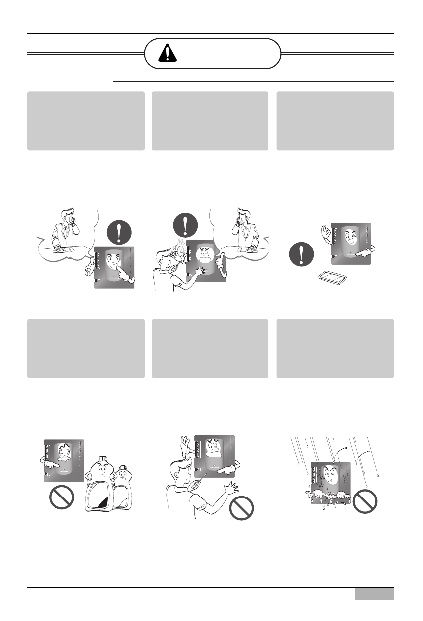
Any question about the
product should be asked to
the service center or the
professional installation
agency.
• The non-professional may
cause accident, electric
shock, explosion or injury.
Consult the service center
or the professional
installation agency about
reinstalling the installed
product.
• The non-professional may
cause accident, electric
shock, explosion or injury.
The standardized part.
• The non-standard part
may cause electric shock,
explosion, injury or failure.
LG-NET 1
MENU/
SELECT
TX
RX
LG-NET 2
TX
RX
LG-NET 3
TX
RX
LG-NET 4
TX
RX
Ethernet 1
ACT
LNK
Ethernet 2
ACT
LNK
Console
Run
Power
TX
RX
FDD
TX
RX
Ext.
TX
RX
DI
1
2
3
4
5
6
7
8
9
10
11
12
13
14
15
16
17
18
19
20
DO
1
2
3
4
Consult the service center
or the professional
installation agency about
reinstalling the installed
product
• The non-professional may
cause electric shock,
explosion or injury.
The flammable gas or the
combustible substance
such as gasoline, benzene
and thinner should not be
used near the power cord.
• It may cause explosion or
fire.
Do not disassemble, repair
or modify the product at
random.
• It may cause electric
shock or fire.
WARNING
■ When installing
TX
LG-NET 1
RX
TX
LG-NET 2
1
DI
2
3
4
5
6
7
8
9
10
11
12
13
14
15
16
17
18
19
20
1
DO
2
3
4
RX
TX
LG-NET 3
RX
TX
LG-NET 4
RX
TX
FDD
RX
TX
Ext.
RX
ACT
Ethernet 1
LNK
MENU/
ACT
Ethernet 2
SELECT
LNK
TX
Console
RX
Run
Power
TX
LG-NET 1
RX
TX
LG-NET 2
1
DI
2
3
4
5
6
7
8
9
10
11
12
13
14
15
16
17
18
19
20
1
DO
2
3
4
RX
TX
LG-NET 3
RX
TX
LG-NET 4
RX
TX
FDD
RX
TX
Ext.
RX
ACT
Ethernet 1
LNK
MENU/
ACT
Ethernet 2
SELECT
LNK
TX
Console
RX
Run
Power
TX
LG-NET 1
RX
TX
LG-NET 2
1
DI
2
3
4
5
6
7
8
9
10
11
12
13
14
15
16
17
18
19
20
1
DO
2
3
4
RX
TX
LG-NET 3
RX
TX
LG-NET 4
RX
TX
FDD
RX
TX
Ext.
RX
ACT
Ethernet 1
LNK
MENU/
ACT
Ethernet 2
SELECT
LNK
TX
Console
RX
Run
Power
Thinner
Wax
TX
LG-NET 1
RX
TX
LG-NET 2
1
DI
2
3
4
5
6
7
8
9
10
11
12
13
14
15
16
17
18
19
20
1
DO
2
3
4
RX
TX
LG-NET 3
RX
TX
LG-NET 4
RX
TX
FDD
RX
TX
Ext.
RX
ACT
Ethernet 1
LNK
MENU/
ACT
Ethernet 2
SELECT
LNK
TX
Console
RX
Run
Power
TX
LG-NET 1
RX
TX
LG-NET 2
1
DI
2
3
4
5
6
7
8
9
10
11
12
13
14
15
16
17
18
19
20
1
DO
2
3
4
RX
TX
LG-NET 3
RX
TX
LG-NET 4
RX
TX
FDD
RX
TX
Ext.
RX
ACT
Ethernet 1
LNK
MENU/
ACT
Ethernet 2
SELECT
LNK
TX
Console
RX
Run
Power
ACP
6
Note for safety
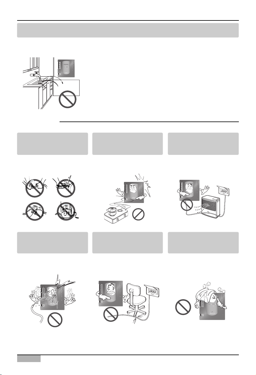
Do not install the product at the wet place.
• It may cause to degrade the insulating ability and may cause fire.
Do not change or extend the
power cord.
• It may cause fire or
electric shock.
Do not place any heating
device near the product.
• It may cause fire.
Do not use any heating
device near the power cord.
• It may cause fire or
electric shock.
Do not let water flow into the
product.
• It may cause electric
shock and failure.
Do not put heavy weight on
the power cord.
• It may cause fire or
electric shock.
Do not put heavy weight on
the product.
• It may cause the failure of
the product.
■ When using
TX
LG-NET 1
RX
TX
LG-NET 2
RX
1
DI
TX
LG-NET 3
2
RX
3
TX
4
LG-NET 4
RX
5
6
7
TX
8
FDD
RX
9
TX
10
Ext.
RX
11
12
13
14
ACT
Ethernet 1
15
LNK
16
MENU/
17
ACT
Ethernet 2
18
LNK
SELECT
19
20
TX
Console
RX
1
Run
DO
2
3
Power
4
TX
LG-NET 1
RX
TX
LG-NET 2
1
DI
2
3
4
5
6
7
8
9
10
11
12
13
14
15
16
17
18
19
20
1
DO
2
3
4
RX
TX
LG-NET 3
RX
TX
LG-NET 4
RX
TX
FDD
RX
TX
Ext.
RX
ACT
Ethernet 1
LNK
MENU/
ACT
Ethernet 2
SELECT
LNK
TX
Console
RX
Run
Power
TX
LG-NET 1
RX
TX
LG-NET 2
RX
1
DI
TX
LG-NET 3
2
RX
3
TX
4
LG-NET 4
RX
5
6
7
TX
8
FDD
RX
9
TX
10
Ext.
RX
11
12
13
14
ACT
Ethernet 1
15
LNK
16
MENU/
17
ACT
Ethernet 2
SELECT
18
LNK
19
20
TX
Console
RX
1
Run
DO
2
3
Power
4
TX
LG-NET 1
RX
TX
LG-NET 2
1
DI
2
3
4
5
6
7
8
9
10
11
12
13
14
15
16
17
18
19
20
1
DO
2
3
4
RX
TX
LG-NET 3
RX
TX
LG-NET 4
RX
TX
FDD
RX
TX
Ext.
RX
ACT
Ethernet 1
LNK
MENU/
ACT
Ethernet 2
SELECT
LNK
TX
Console
RX
Run
Power
TX
LG-NET 1
RX
TX
LG-NET 2
RX
1
DI
TX
LG-NET 3
2
RX
3
TX
4
LG-NET 4
RX
5
6
7
TX
8
FDD
RX
9
TX
10
Ext.
RX
11
12
13
14
ACT
Ethernet 1
15
LNK
16
MENU/
17
ACT
Ethernet 2
SELECT
18
LNK
19
20
TX
Console
RX
1
Run
DO
2
3
Power
4
TX
LG-NET 1
RX
TX
LG-NET 2
1
DI
2
3
4
5
6
7
8
9
10
11
12
13
14
15
16
17
18
19
20
1
DO
2
3
4
RX
TX
LG-NET 3
RX
TX
LG-NET 4
RX
TX
FDD
RX
TX
Ext.
RX
ACT
Ethernet 1
LNK
MENU/
ACT
Ethernet 2
SELECT
LNK
TX
Console
RX
Run
Power
Installation/Owner's Manual
7
Note for safety
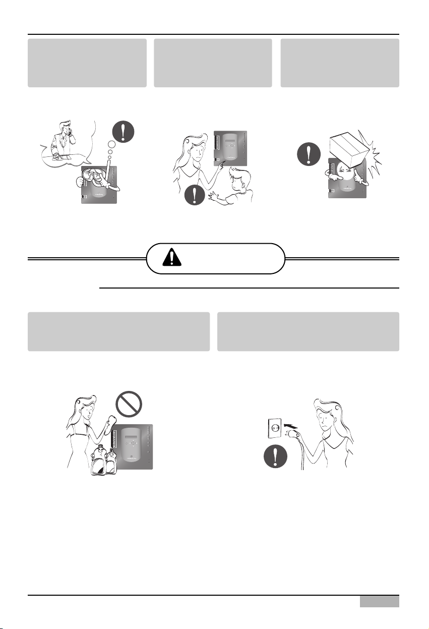
CAUTION
If the product is flooded,
consult the service centre or
the professional installation
agency.
• It may cause fire or
electric shock.
Let the children or the old
and the weak be controlled
by the guardian to use.
• It may cause accident or
failure.
Do not give any shock to the
product.
• Any shock to the product
may cause failure.
Do not use strong detergent such as
solvent, but a soft cloth.
• It may cause fire or to deform the product.
Grab the head of the plug of the power cord
to pull when disconnecting the plug, and do
not touch the plug with wet hands.
• It may cause fire or electric shock.
■ When using
1
DI
2
3
4
5
6
7
8
9
10
11
12
13
14
15
16
MENU/
17
SELECT
18
19
20
1
DO
2
3
4
TX
LG-NET 1
RX
TX
LG-NET 2
RX
TX
LG-NET 3
RX
TX
LG-NET 4
RX
TX
FDD
RX
TX
Ext.
RX
ACT
Ethernet 1
LNK
ACT
Ethernet 2
LNK
TX
Console
RX
Run
Power
TX
LG-NET 1
RX
TX
LG-NET 2
RX
1
DI
TX
LG-NET 3
2
RX
3
TX
4
LG-NET 4
RX
5
6
7
TX
8
FDD
RX
9
TX
10
Ext.
RX
11
12
13
14
ACT
Ethernet 1
15
LNK
16
MENU/
17
ACT
Ethernet 2
SELECT
18
LNK
19
20
TX
Console
RX
1
Run
DO
2
3
Power
4
1
2
3
4
5
6
7
8
9
10
11
12
13
14
15
16
17
18
19
20
1
2
3
4
TX
LG-NET 1
RX
TX
LG-NET 2
RX
DI
TX
LG-NET 3
RX
TX
LG-NET 4
RX
TX
FDD
RX
TX
Ext.
RX
ACT
Ethernet 1
LNK
MENU/
ACT
Ethernet 2
SELECT
LNK
TX
Console
RX
Run
DO
Power
TX
LG-NET 1
RX
TX
LG-NET 2
RX
TX
LG-NET 3
RX
TX
LG-NET 4
RX
TX
FDD
RX
TX
Ext.
RX
ACT
Ethernet 1
LNK
MENU/
ACT
Ethernet 2
SELECT
LNK
TX
Console
RX
Run
Power
Wax
1
2
3
4
5
6
7
8
9
10
11
12
13
14
15
16
17
18
19
20
1
2
3
4
Thinner
DI
DO
ACP
1-1
1. ACP Functions & Specification
Functions of ACP
1. ACP Functions & Specification
The ACP(Advanced Control Platform) is the central controller which can control up to 256 indoor units
of the airconditioner at one place individually or totally. The ACP can monitor or control to operate the
airconditioner and the ventilator installed at each room of the building from the place such as the
control room of a building, the administrative room of a school.
Main functions of the ACP are as follows:
Using the external button of the ACP to set the environment
The following functions can be set by using the external buttons of the ACP.
• Set the network environment (IP address, net mask, gateway)
• Set one of Peak/Demand function to use
• Set the language displayed on the LG ACCS screen
• Set whether to use the schedule feature or not
• Set whether to use the watthour meter feature or not.
Installation/Owner's Manual
1-2
1. ACP Functions & Specification
Built-in Web server
Various functions of contents can be used when the IP address of the ACP is entered at the address
window by using the Internet Explorer without installing a separate PC program to automatically
execute the central control program at the ACP web server.
Also, the demand control feature to control the demand power is controlled by directly connecting the
ACP to the demand controller without installing a separate PC program.
Interconnecting with the AC Manager
Various features offered by the AC Manager are offered by connecting the AC Manager program
installed at the PC to the ACP. Especially, when using the schedule feature of the AC Manager,
because the ACP has its own engine, even though the user turns off the PC where the AC Manager is
installed, the ACP can perform the schedule featre by itself.
➲ Control 256 indoor units of the airconditioner at
maximum
➲ Monitoring the error and operation state
➲ Controlling the peak/demand electric power
➲ Setting the system
TX
LG-NET 1
RX
TX
LG-NET 2
RX
TX
LG-NET 3
RX
TX
LG-NET 4
RX
TX
FDD
RX
TX
Ext.
RX
ACT
Ethernet 1
LNK
ACT
Ethernet 2
LNK
TX
Console
RX
Run
Power
Internet
Explorer
1
DI
2
3
4
5
6
7
8
9
10
11
12
13
14
15
16
MENU/
17
SELECT
Internet
18
19
20
1
DO
2
3
4
ACP
TX
LG-NET 1
RX
TX
LG-NET 2
RX
TX
LG-NET 3
RX
TX
LG-NET 4
RX
TX
FDD
RX
TX
Ext.
RX
ACT
Ethernet 1
LNK
ACT
Ethernet 2
LNK
TX
Console
RX
Run
Power
AC Manager
HUB
1
DI
2
3
4
5
6
7
8
9
10
11
12
13
14
15
16
MENU/
17
SELECT
18
19
20
1
DO
2
3
4
ACP
ACP
1-3
1. ACP Functions & Specification
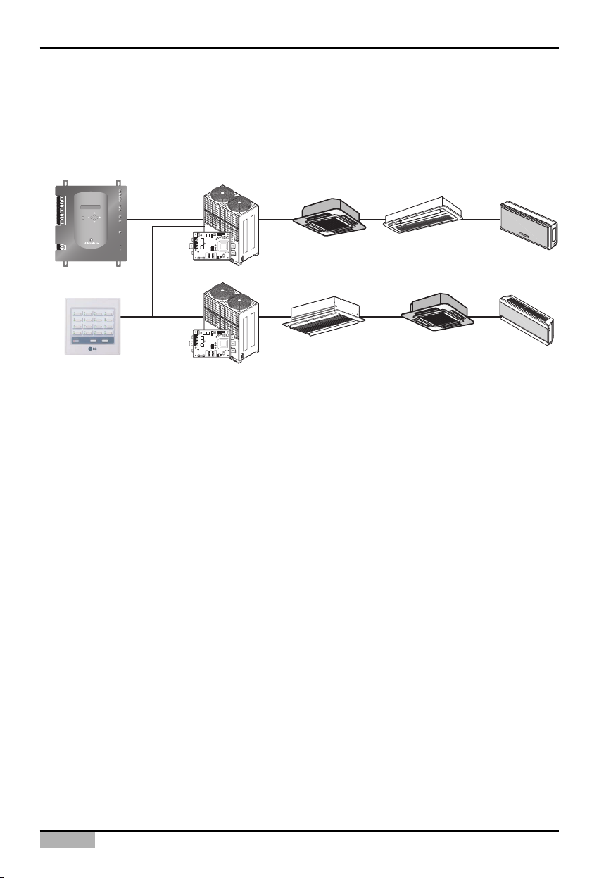
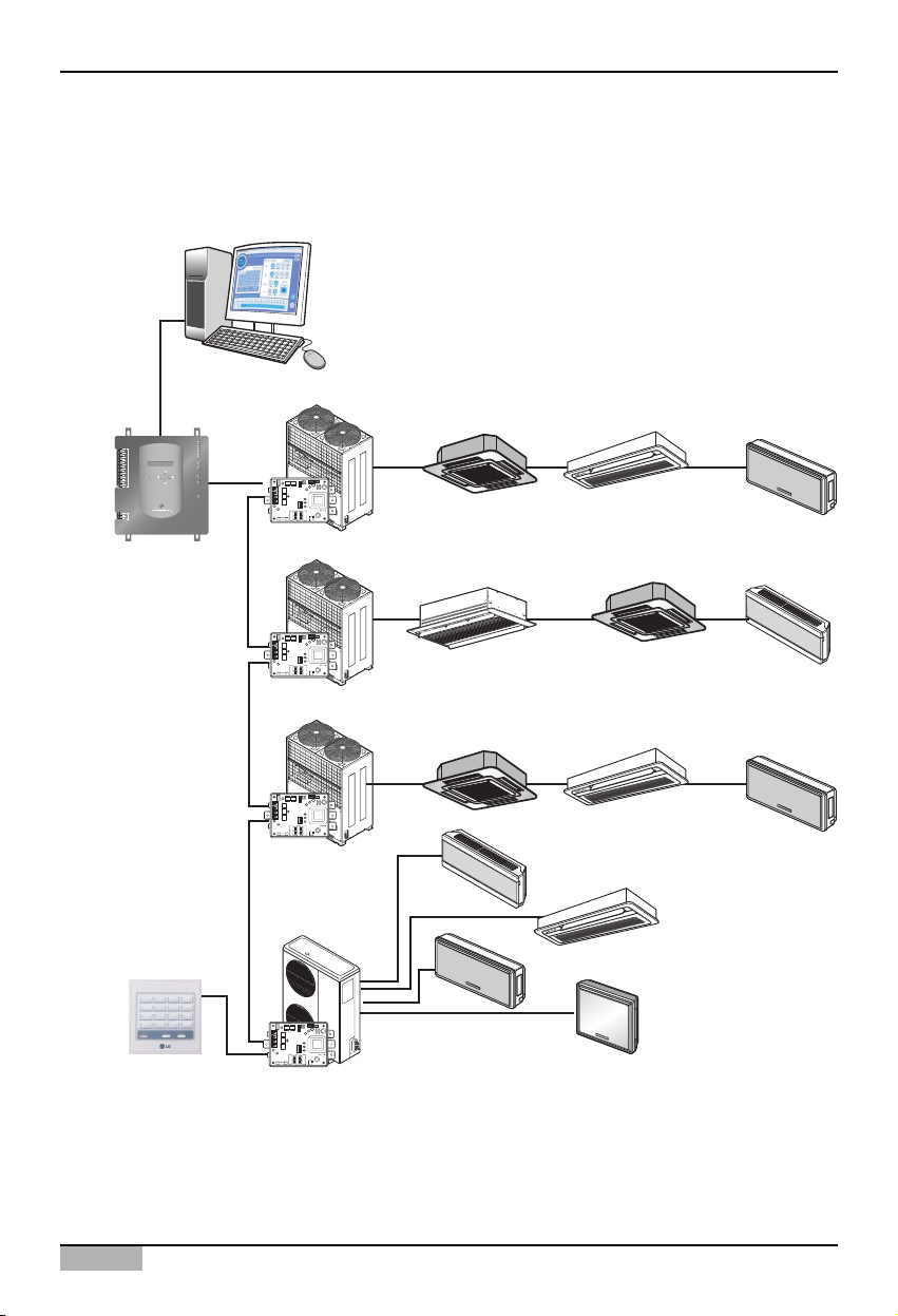
Interconnecting with the simple central controller
The 16-room simple central controller can be interconnected with the ACP. When the ACP centrally
controlling all airconditioners and the simple central controller at each floor of the building are used
together, the airconditioner can be controlled more easily.
TX
LG-NET 1
RX
TX
LG-NET 2
1
DI
2
3
4
5
6
7
8
9
10
11
12
13
14
15
16
17
18
19
20
1
DO
2
3
4
RX
TX
LG-NET 3
RX
TX
LG-NET 4
RX
TX
FDD
RX
TX
Ext.
RX
ACT
Ethernet 1
LNK
MENU/
ACT
SELECT
Ethernet 2
LNK
TX
Console
RX
Run
Power
ACP
Simple central controller
PI485
PI485
ON
L1 2 3 4
KSDO4H
ON
L1 2 3 4
KSDO4H
Multi V
Multi V
00
Central control
address
Central control
address
(0.0) (0.1) (0.F)
(0.0) (0.1) (0.F)
Installation/Owner's Manual
1-4
1. ACP Functions & Specification
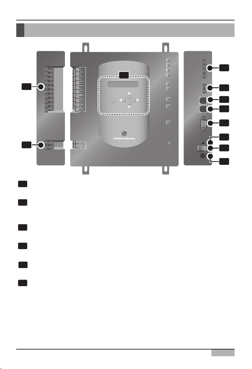
Denomination of ACP
1
6
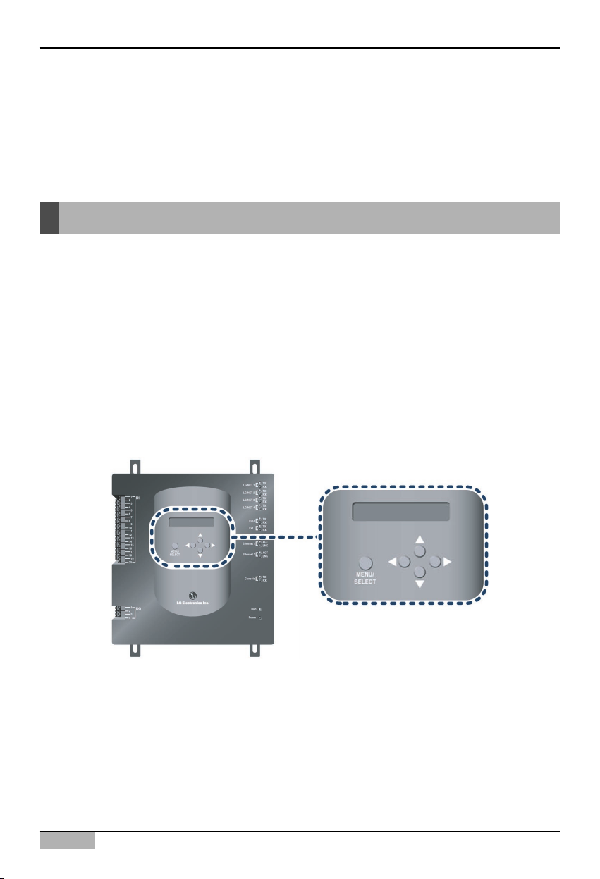
Buttons and LCD
Buttons and the LCD to display the network environment setting and other information
RS485 communication port (for PI485 connection)
RS485 communication port connecting to the PI485 to connect the airconditioner and the
ventilator (4EA in total)
RS485 communication port (for external extension)
RS485 communication port spar for exter extension (2EA in total)
Ethernet port (for connecting the Internet and the AC Manager)
The Ethernet port for connecting the Internet and the AC Manager
Ethernet port (spare)
Ethernet port spare for the function extension of the ACP
RS232 port
RS232 port for updating the software of the ACP
6
5
4
3
2
1
1
DI
2
3
4
5
6
7
8
9
10
10
11
12
13
14
15
16
17
18
19
20
MENU/
SELECT
TX
LG-NET 1
RX
TX
LG-NET 2
RX
LG-NET 3
LG-NET 4
FDD
Ext.
Ethernet 1
Ethernet 2
Console
TX
RX
TX
RX
TX
RX
TX
RX
ACT
LNK
ACT
LNK
TX
RX
2
3
4
5
11
1
DO
2
3
4
Run
Power
7
8
9

ACP
1-5
Note: External input/output signal terminal
9 external input signal terminal and 10 external output signal terminal are configured at the
PQCPB11A0E only. These terminals are used to connect the AC Manager to set the fire control
function. These terminal are used to set the indoor unit to operate or stop for responding High or Low
signal of each external input signal.
In case of PQCPA11A0E model, a separate IO Kit (Model: PQCPE11A0E) can be purchased and
installed to use for connecting the external signal.
1. ACP Functions & Specification
Reset switch
Switch for resetting the ACP by the software
Power switch
Switch for turning on/off the ACP
Adaptor connection port
Port for DC 12V to connect the adaptor supplying the power
External input signal terminal
Port for connecting the external input signal (20EA in total). Input terminal not requiring the
power.
External output signal terminal
Connection port spare for the function extension of the ACP (4EA in total)
11
10
9
8
7
Installation/Owner's Manual
1-6
1. ACP Functions & Specification
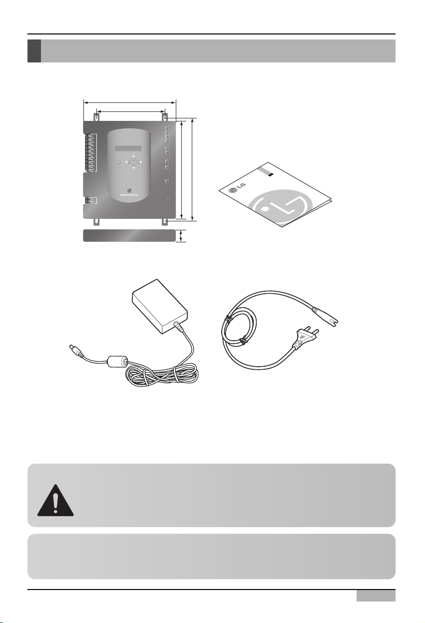
Components of ACP
The following components are contained within the packaging box of the ACP. Open the packaging
box of the ACP to make sure that all components are contained.
LG
ACP
(Advanced Control Platform)
Adaptor for Power supply
Input: 100~240V
AC 50/60Hz 1.5A
Output: DC 12V
3.33A, 40W MAX
Power Cord
International Standard
IEC320 C14 Type
ACP
Installation/Owner's Manual
Notice : In Australia, purchase the power code
In Australia, the power code from local area.
The power code is not included in the package
Caution: Using the standardized part
We are not responsible for any problem caused by using the adaptor other than the
standardized one offered by us, so using any non-standard part should be prohibited.
You can consult the LG System Air Conditioner Support Division about the applicable
product.
237mm
180mm
TX
LG-NET 1
RX
TX
LG-NET 2
1
DI
2
3
4
5
6
7
8
9
10
11
12
13
14
15
16
MENU/
17
SELECT
18
19
20
1
DO
2
3
4
RX
TX
LG-NET 3
RX
TX
LG-NET 4
RX
TX
FDD
RX
TX
Ext.
RX
250mm
273mm
ACT
Ethernet 1
LNK
ACT
Ethernet 2
LNK
TX
Console
RX
Run
Power
57mm

ACP
1-7
1. ACP Functions & Specification
Hardware Specification of ACP
Item Description
CPU PXA255-400MHz Xscale
RAM 128MB (32x4) SDRAM
ROM • 512KB NOR Flash – Boot image
• 128MB (64x2) NAND Flash – Program image, Database, others
RS-232 Console For updating the program (for developing)
Communication port
• RS485 port: PI485 communication port 4EA, External device
connection port 2EA
• RS-232 communication port: Port for updating the program 1EA
• Ethernet port: for Internet connectioin 1EA (10Base-T) Spare 1EA
For the PQCPB11A0E model, the following ports are supplied as default.
• External input port: 20EA (Pulse contable, DC 12V)
• External output port: 4EA (Relay output, 5V)
For the PQCPA11A0E model, the IO Kit (PQCPE11A0E) should be
separately purchased for connecting the above port
LED
20EA (for displaying RS communication status, Ethernet communication
status, RS232 communication status, Power operation status)
LCD
16x2 Character, displaying Network environment setting and information
Note: License policy
This product follows the GPL(General Public License) for using the embedded Linux.

Installation/Owner's Manual
2-1
2. Installing ACP
This chapter describes how to install the ACP to use.
In order to use the ACP, the environment for the ACP, the indoor unit and the ventilator to
communicate should be built and the indoor unit should be registered.
In order to use the ACP, the installation should be performed by the following order.
STEP 1. Check the environment before installing the ACP
Before installing the ACP, check the network configuration according to the
interconnection between the ACP and the external device.
STEP 2. Set the indoor unit address and Connecting the PI485
Set the address of the ACP not overlapped with the connecting indoor unit and connect
the PI485.
STEP 3. Install the ACP and set the environment and the function
Install the ACP and set the network environment and the function.
STEP 4. ACCS access and Information input
Set the access environment at the LG ACCS, the ACP operation program and enter the
air conditioner information.
STEP 5. Make sure and check the ACP installation
Make sure and check that the ACP is normally installed.
2. Installing ACP
Caution: Installing the ACP
The ACP installation work needs the professional technique. Therefore, the
installation described at this chapter should be performed by the certified
installation professional.
Consult the service center or the professional installation agency certified by us about
any question or request related to the installation.

ACP
2-2
2. Installing ACP
Before installing the ACP
ACP provides 4 RS485 ports to connect the indoor unit. Maximum of 16 units can be connected to
PI485 for outdoor unit in 1 RS385 port, and maximum of 31 units for SINGLE/Ventilator PI485.
256 indoor units at maximum can be connected to one ACP. All of 256 indoor units may be connected
to one RS485 port, which is the maximum number of units for the ACP to connect. But, in order to
improve the communication performce of the RS485, we recommend to distribute them to four ports.
By considering three following cases using the ACP, perform the installation after carefully considering
how to use.
• Install the single ACP to use as web server
• Connect the single ACP to the AC Manager to use
• Connect more than one ACP to the AC Manager via the hub to use
Note: Change the number of connections of RS485
If it is inevitable to change the above specification, call the system air conditioner support division
Installation/Owner's Manual
2-3
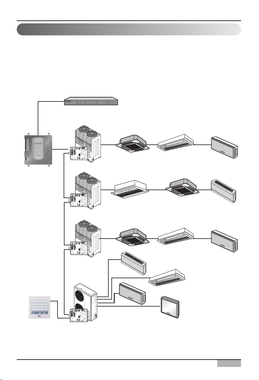
2. Installing ACP
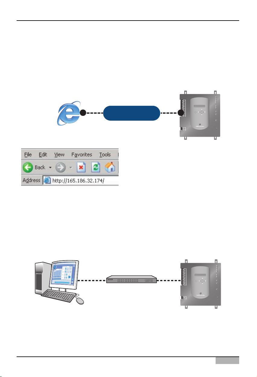
When one ACP is used as web server, the ACP should be connected with the network structure as
shown at the following examples.
Using the hub
If it is connected via the hub, the network can be configured as shown at the following example.
Using the single ACP as web server
LAN
(Direct Cable)
Hub
Multi V
TX
LG-NET 1
RX
TX
LG-NET 2
MENU/
SELECT
ACP
RX
TX
LG-NET 3
RX
TX
LG-NET 4
RX
TX
FDD
RX
TX
Ext.
RX
ACT
Ethernet 1
LNK
ACT
Ethernet 2
LNK
TX
Console
RX
Run
Power
PI485
ON
L1 2 3 4
KSDO4H
Multi V
1
DI
2
3
4
5
6
7
8
9
10
11
12
13
14
15
16
17
18
19
20
1
DO
2
3
4
00 01 02
10
11 12
Simple central controller
(possible to connect
when necessary)
PI485
PI485
PI485
ON
L1 2 3 4
KSDO4H
Multi V
ON
L1 2 3 4
KSDO4H
Multi
ON
L1 2 3 4
KSDO4H
20 21 22
30
31
32
33
ACP
2-4
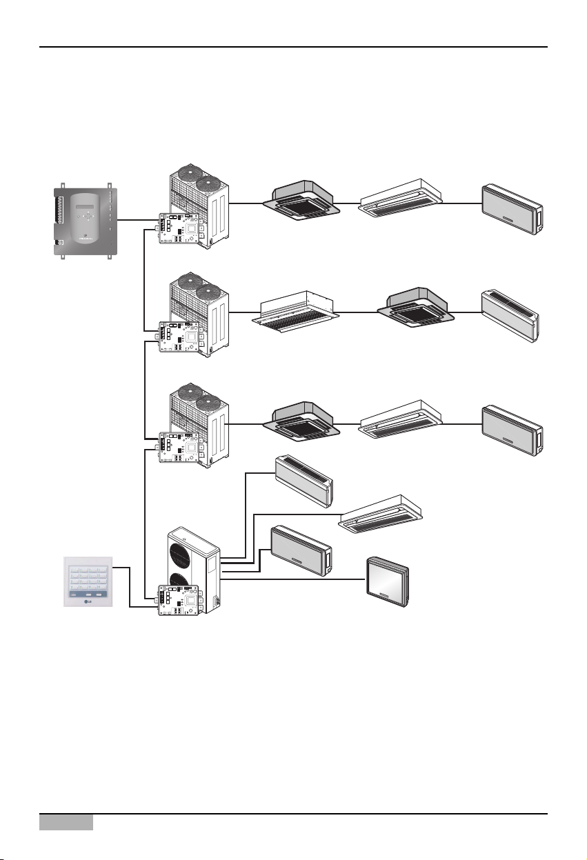
2. Installing ACP
Not using the hub
If it is connected without the hub, the network can be configured as shown at the following example.
Multi V
00 01 02
TX
LG-NET 1
RX
TX
LG-NET 2
MENU/
SELECT
ACP
RX
TX
LG-NET 3
RX
TX
LG-NET 4
RX
TX
FDD
RX
TX
Ext.
RX
ACT
Ethernet 1
LNK
ACT
Ethernet 2
LNK
TX
Console
RX
Run
Power
PI485
ON
L1 2 3 4
KSDO4H
Multi V
10
ON
L1 2 3 4
KSDO4H
11 12
1
DI
2
3
4
5
6
7
8
9
10
11
12
13
14
15
16
17
18
19
20
1
DO
2
3
4
PI485
Multi V
20 21 22
Simple central controller
(possible to connect
when necessary)
PI485
PI485
ON
L1 2 3 4
KSDO4H
Multi
ON
L1 2 3 4
KSDO4H
30
31
32
33
Installation/Owner's Manual
2-5
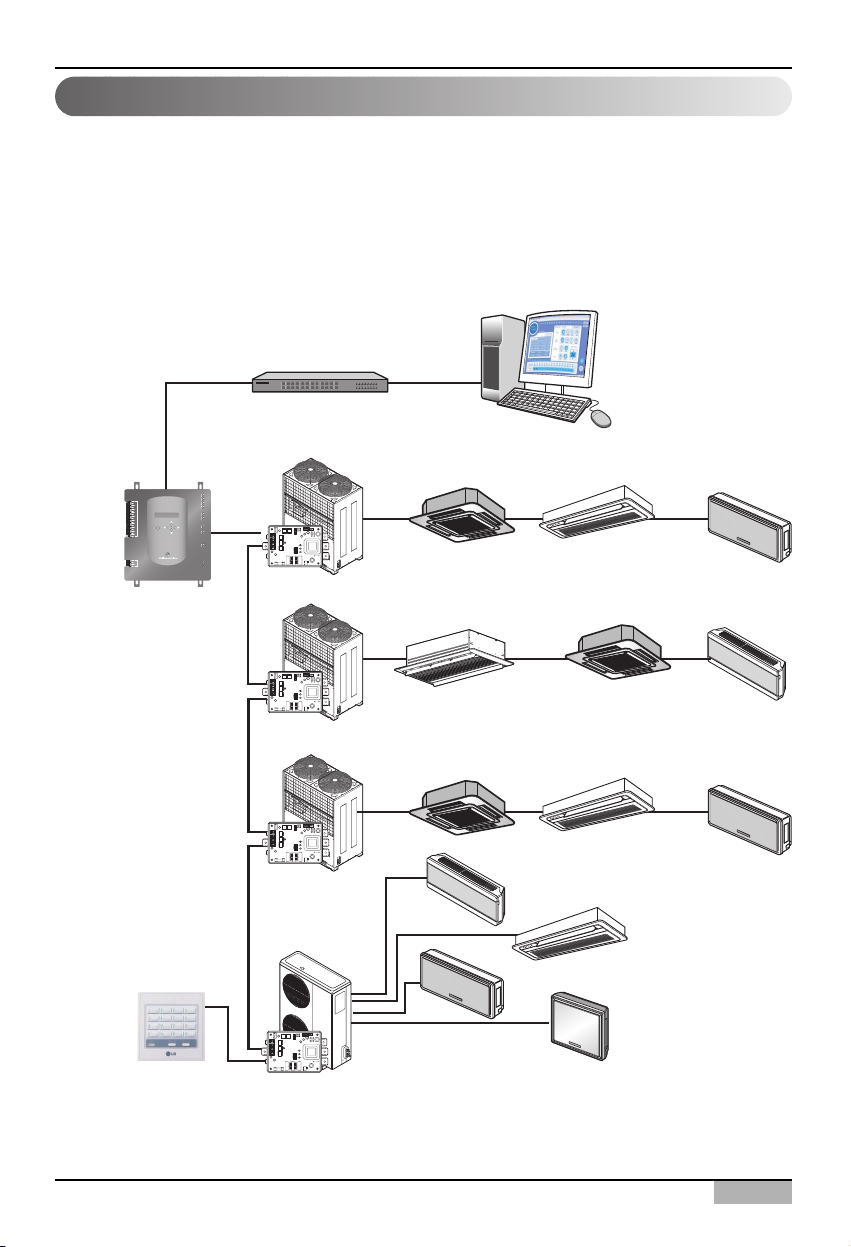
2. Installing ACP
When one ACP is connected to the AC Manager without the hub, the ACP should be
connected with the network structure as shown at the following examples.
Using the hub
If it is connected via the hub, the network can be configured as shown at the following example.
Connecting the single ACP to the AC Manager
AC Manager
LAN
(Direct Cable)
1
DI
2
3
4
5
6
7
8
9
10
11
12
13
14
15
16
17
18
19
20
1
DO
2
3
4
MENU/
SELECT
ACP
Hub
Multi V
TX
LG-NET 1
RX
TX
LG-NET 2
RX
TX
LG-NET 3
RX
TX
LG-NET 4
RX
TX
FDD
RX
TX
Ext.
RX
ACT
Ethernet 1
LNK
ACT
Ethernet 2
LNK
TX
Console
RX
Run
Power
PI485
ON
L1 2 3 4
KSDO4H
00 01 02
Multi V
11 12
PI485
10
ON
L1 2 3 4
KSDO4H
Multi V
20 21 22
ON
L1 2 3 4
KSDO4H
PI485
Multi
30
31
32
Simple central controller
(possible to connect
when necessary)
PI485
33
ON
L1 2 3 4
KSDO4H
ACP
2-6
2. Installing ACP
Not using the hub
If it is connected without the hub, the network can be configured as shown at the following example.
AC Manager
LAN
Cross cable
1
DI
2
3
4
5
6
7
8
9
10
11
12
13
14
15
16
17
18
19
20
1
DO
2
3
4
MENU/
SELECT
ACP
TX
LG-NET 1
RX
TX
LG-NET 2
RX
TX
LG-NET 3
RX
TX
LG-NET 4
RX
TX
FDD
RX
TX
Ext.
RX
ACT
Ethernet 1
LNK
ACT
Ethernet 2
LNK
TX
Console
RX
Run
Power
PI485
PI485
Multi V
ON
L1 2 3 4
KSDO4H
Multi V
ON
L1 2 3 4
KSDO4H
Multi V
00 01 02
10
20 21 22
11 12
Simple central controller
(possible to connect
when necessary)
PI485
PI485
ON
L1 2 3 4
KSDO4H
Multi
ON
L1 2 3 4
KSDO4H
30
31
32
33
Installation/Owner's Manual
2-7
2. Installing ACP
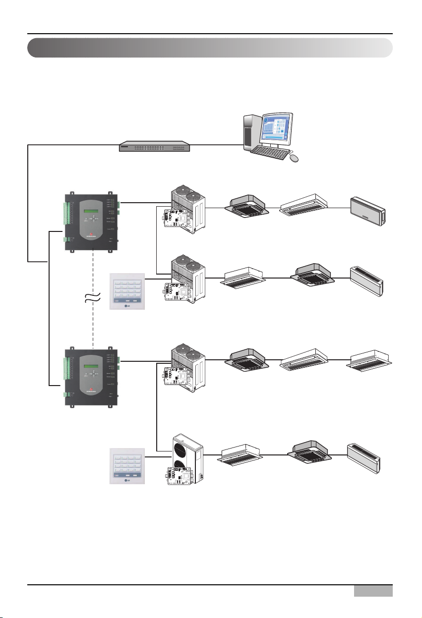
When more than one ACP are connected to the AC Manager via the hub, the ACP should be
connected with the network structure as shown at the following examples.
Connecting more than on ACPs to the AC Manager
LAN
Direct cable
ACP
ACP
Hub
PI485
PI485
Simple central controller
(possible to connect
when necessary)
PI485
Multi V
L1 2 3 4
KSDO4H
Multi V
ON
L1 2 3 4
KSDO4H
Multi V
ON
L1 2 3 4
KSDO4HON
Multi
AC Manager
00 01 02
10 11 12
20 21 22
30 31 32
Simple central controller
(possible to connect
when necessary)
PI485
ON
L1 2 3 4
KSDO4H
ACP
2-8
2. Installing ACP
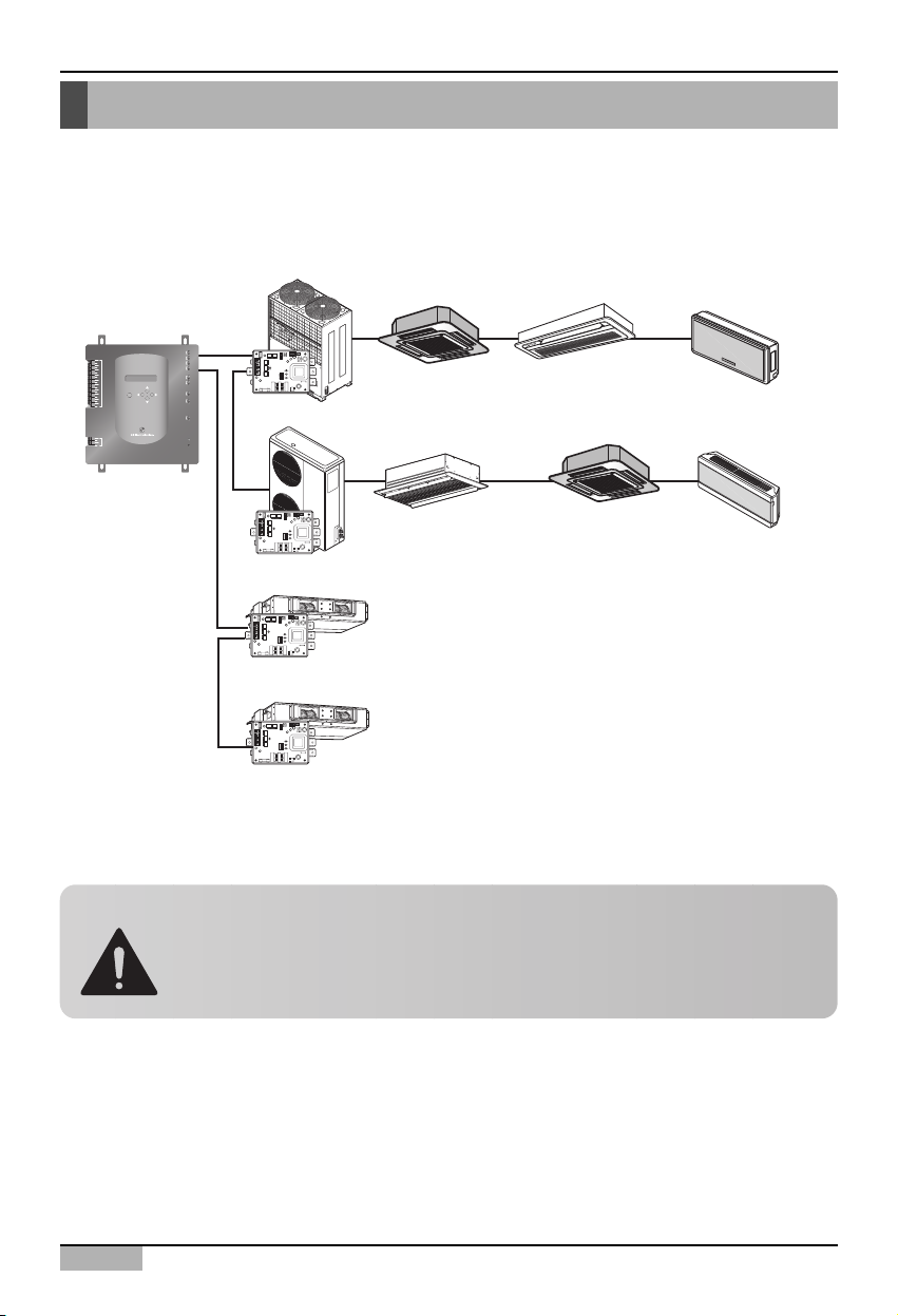
Setting the indoor unit address
By considering the entire installation configuration connecting to one ACP, set the address to each
indoor unit not to be overlapped. 00~FF in hexadecimal can be set to the indoor unit address.
The next section describes how to set the address to each indoor unit by using the wired or wireless
remote controller according to the given number.
The following example sets the address to the indoor unit.
When the ACP is interconnected with the AC Manager, the ventilator can be together installed and
controlled. The above figure shows the example that sets 30 and 31 to the ventilators as address and
connects to the ACP.
Caution: Connecting the ventilator to the RS485
The ventilator and the air conditioner can not be connected together to the same
RS485 communication cable. When connecting the ventilator to the RS485
communication cable, the cable other than the RS485 communication cable
connecting the air conditioner should be used.
Multi V
00 01 02
TX
LG-NET 1
RX
TX
LG-NET 2
1
DI
2
3
4
5
6
7
8
9
10
11
12
13
14
15
16
MENU/
17
SELECT
18
19
20
1
DO
2
3
4
RX
TX
LG-NET 3
RX
TX
LG-NET 4
RX
TX
FDD
RX
TX
Ext.
RX
ACT
Ethernet 1
LNK
ACT
Ethernet 2
LNK
TX
Console
RX
Run
Power
PI485
ON
L1 2 3 4
KSDO4H
Multi
10
11 12
ACP
ON
L1 2 3 4
KSDO4H
Ventilator
30
ON
L1 2 3 4
KSDO4H
PI485
Ventilator
31
ON
L1 2 3 4
KSDO4H
PI485
Installation/Owner's Manual
2-9
2. Installing ACP
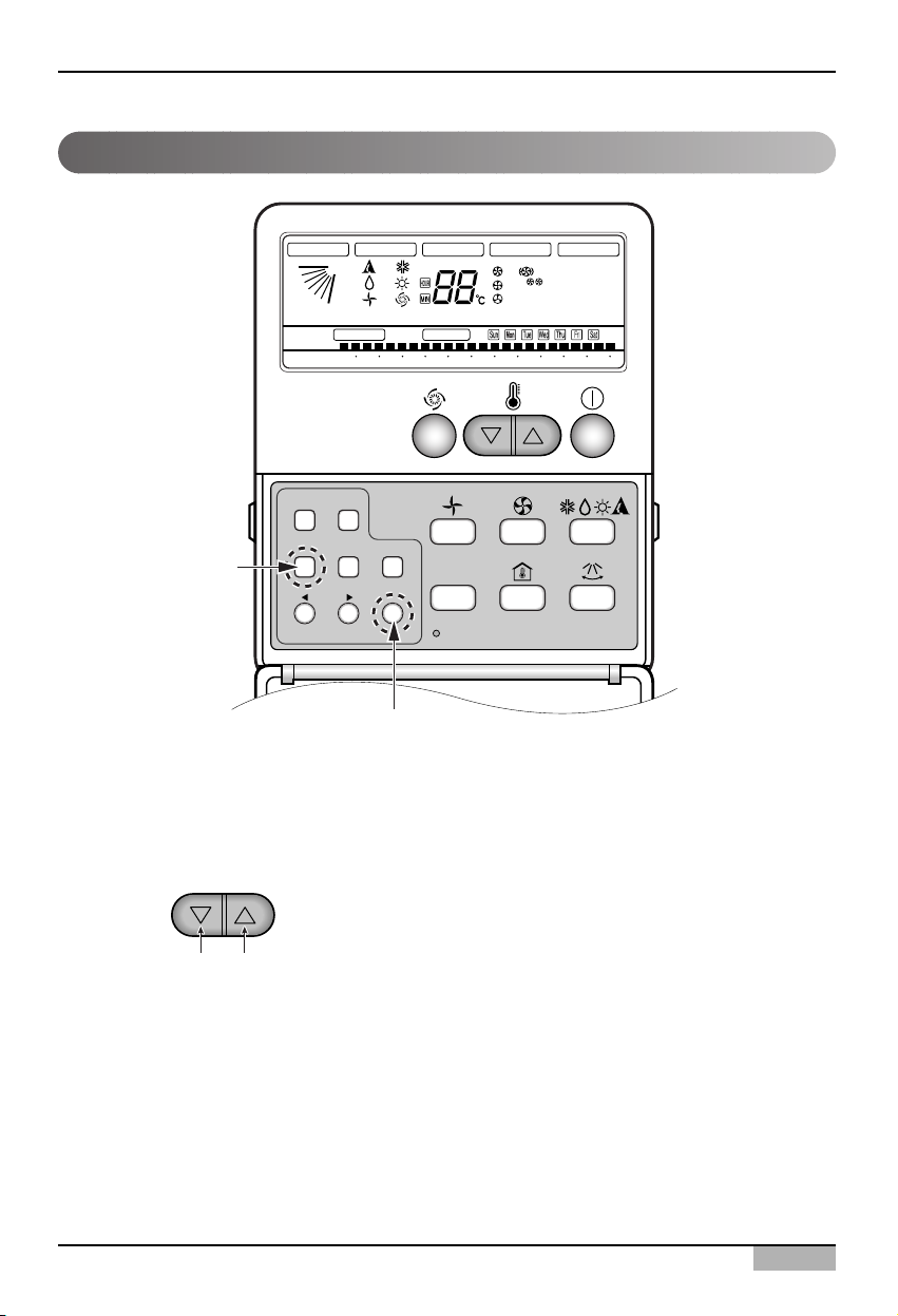
Setting address with wired remote controller
Timer Cancel
Program Week
Hour Min
Holiday
Set/Clr
RESET
ZONE
1234
Operation unit
Humidify
JET
AUTO
AUTO SWING OPERATION
FAN SPEED
Program set
SUB FUNCTION
SET TEMP
Room Temp
HI
MED
LO
Heater
Defrost
Filter
Preheat
Out door
Time
Timer
On
Set no. Time
Off
01 03 05 07 09 11 13 15 17 19 21 23
Plasma
Program
Set/Ctl
1. Press Week Program & Set/Clr keys at the same time.
2. Set the indoor unit address using the temperature controller.
Allowed Range : 00-FF
3. Complete the address setting to press the week Program & Set/Clr keys at the same time for 3
seconds.
❈ Some remote controllers may not be suported by above functions, a coording to the production date
of wired/wireless remote conrollers. As it has no concem with customers' use, use the remote
controller available for the address setting during installation.
Group No. Indoor Unit No.
EX)
3A
ACP
2-10
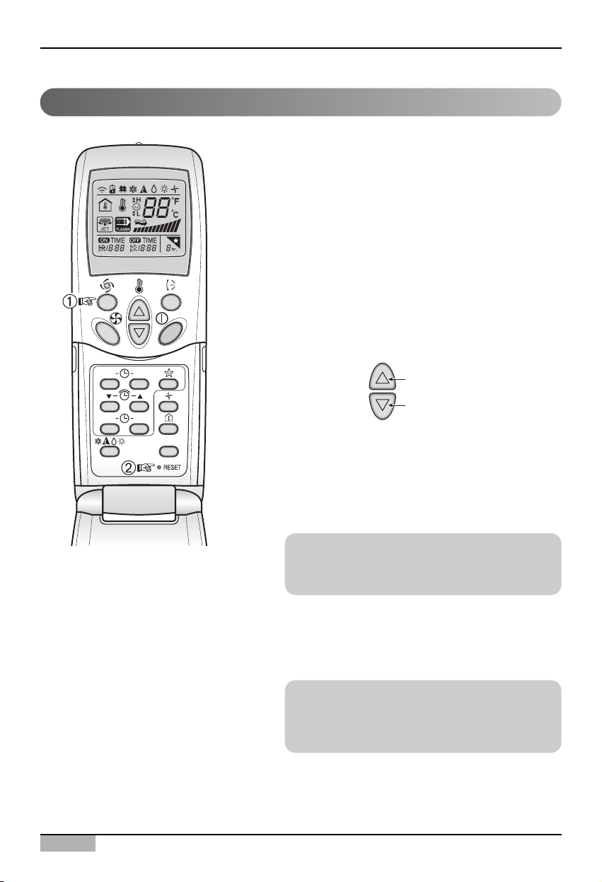
2. Installing ACP
You can set the address of the indoor unit through the
wireless remote controller that controls the indoor
unit. To set the address of the indoor unit with the
wireless remote controller, proceed as follows.
1. With the [Power Cool] button pressed, press the
[RESET] button. The [Power Cool] button must be
pressed for more than 3 seconds.
2. Use the [Temperature Adjustment] button to set the
address of the indoor unit.
3. After setting the address, press the [Operate/Stop]
button once toward the indoor unit.
4. When the set address is displayed on the indoor
unit, the address setting is complete.
5. When you reset the remote controller, it switches
from the address setting mode to general operation
mode.
Setting address with wireless remote controller
Reference: Address display time and method
The address display time and method may differ
by the type of the indoor unit.
Reference: Type of remote controller
When using a different type of remote controller
from the one described above, refer to the user
manual of the applicable remote controller.
Group No.
Indoor unit No.
Temperature
adjustment
ON OFF
SET
CANCEL
PLASMA
Installation/Owner's Manual
2-11
2. Installing ACP
ON OFF
SET
CANCEL
PLASMA
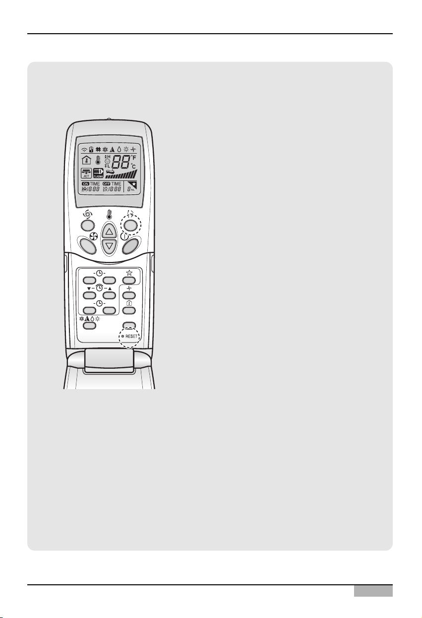
Information: Checking the set address
You can check the set address by using the
wireless remote controller. To check the set
address, proceed as follows.
1. With the [Wind Up/Down] button pressed,
press the [RESET] button. The [Wind
Up/Down] button must be pressed for more
than 3 seconds.
2. Press the [Operate/Stop] button once toward
the indoor unit. The set address will be shown
on the display part of the indoor unit. The
address display time and method can differ by
the type of indoor unit.
3. Reset the remote controller again to use it in
general operation mode.
ACP
2-12
2. Installing ACP
Setting the PI485 and Connecting the cable
After setting the address of the indoor unit, install the PI485 and set the DIP switch. And then, connect
the RS485 cable for communicating with the ACP.
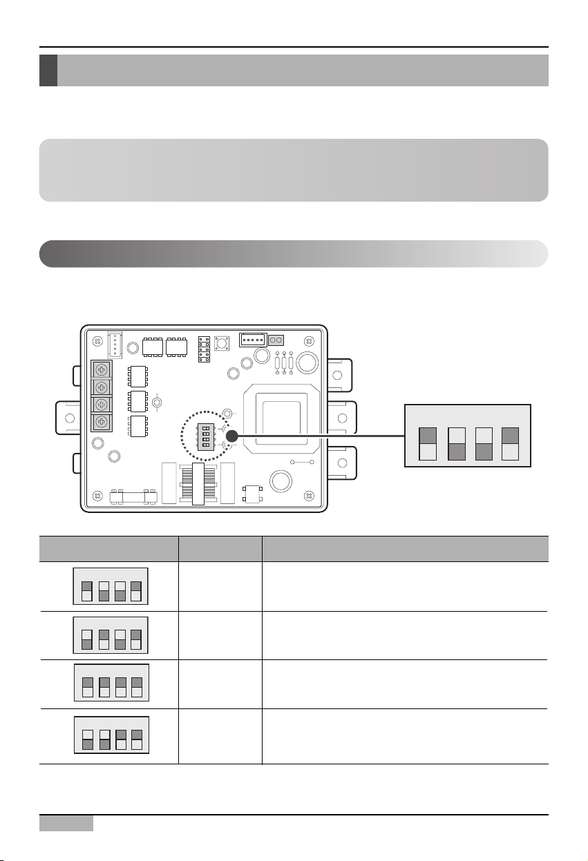
After installing the PI485 suitable to the product, the DIP switch should be set. The DIP switch of the
PI485 can be checked at the following place.
Setting the PI485 DIP switch
Dip switch Setting Product type
1, 4 ON - Multi V product(CRUN, LRA product excluded)
2, 3 OFF - MPS product with the common PCB applied
- MPS inverter product
2, 4 ON
- MPS product with the common PCB not applied
1, 3 OFF
1, 2, 3, 4 ON - Multi V CRUN, LRA product
3, 4 ON
- Single indoor unit (connected to the PI485 for the
indoor unit)
- Ventilator (connected to the PI485 for ventilating)
O N K S D O 4 H
O N K S D O 4 H
O N K S D O 4 H
O N K S D O 4 H
Note: Installing the PI485
Installing the PI485 deponds on the outdoor unit. So, install the PI485 by referring to the PI485
manual or the installation technique information.
ON
L1 2 3 4
KSDO4H
O N K S D O 4 H
Installation/Owner's Manual
2-13
2. Installing ACP
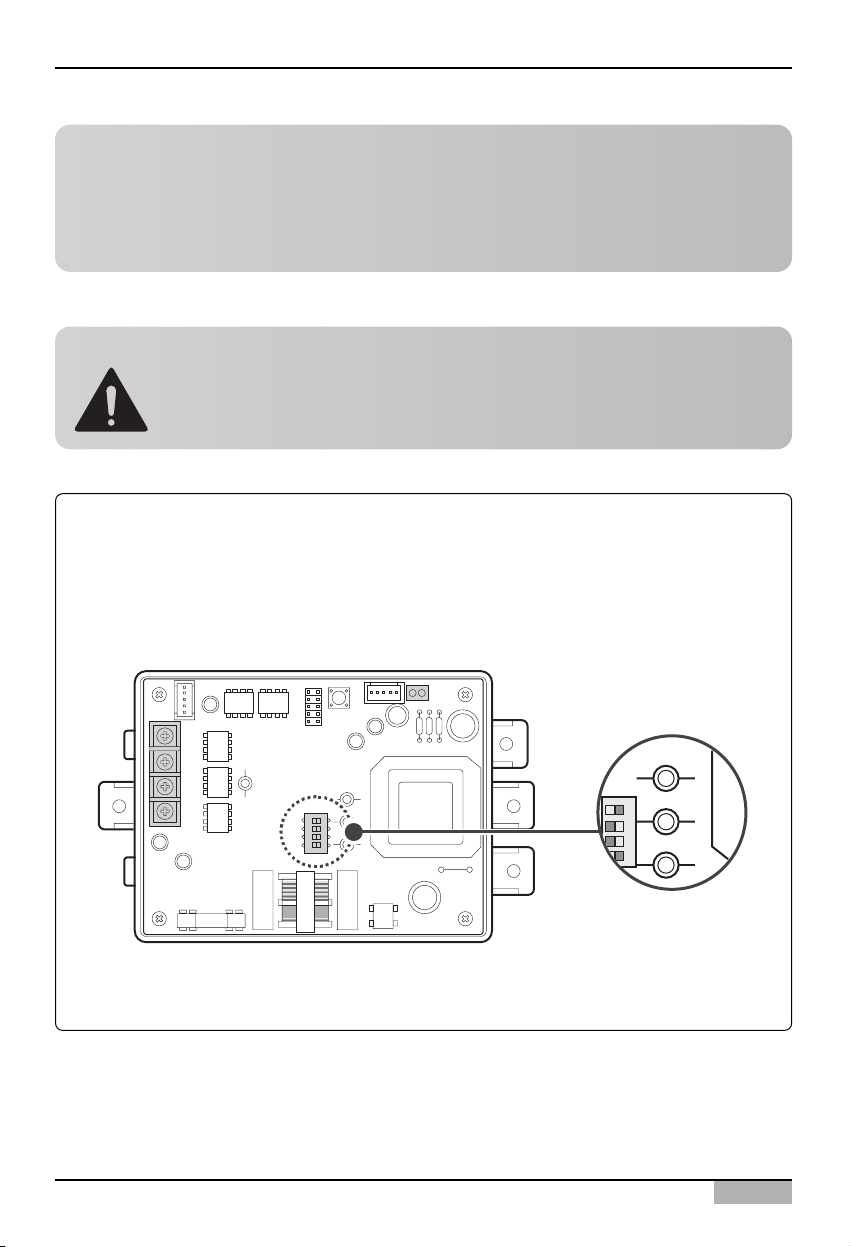
Tip: Checking the PI485 DIP switch setting
It can be checked whether the indoor unit address and the DIP switch of the PI485 are correctly set
as follows:
• The LED01G blinks as many as the number of the connected indoor units.
• The LED02G and the LED03G continue to blink alternately. (When the LRA/CRUN is
connected, the LED02G may blink more than the LED03G.)
If the LED is abnormally different from the above description, check again the indoor unit address
setting and the DIP switch setting.
O N K S D O 4 H
Note: PCB part number
The MPS product with the common PCB applied has the following PCB part number:
• PCB P/NO. : 6871A20910A ~ Z
• PCB P/NO. : 6871A20917A ~ Z
• PCB P/NO. : 6871A20918A ~ Z
Caution: Setting the PI485 DIP switch
If the air conditioner selection switch is incorrectly set, the air conditioner may
incorrectly operate.
For more information about installing the PI485, see the PI485(M) manual.
LED03G
ON
L1 2 3 4
KSDO4H
LED02G
LED01G
ACP
2-14
2. Installing ACP
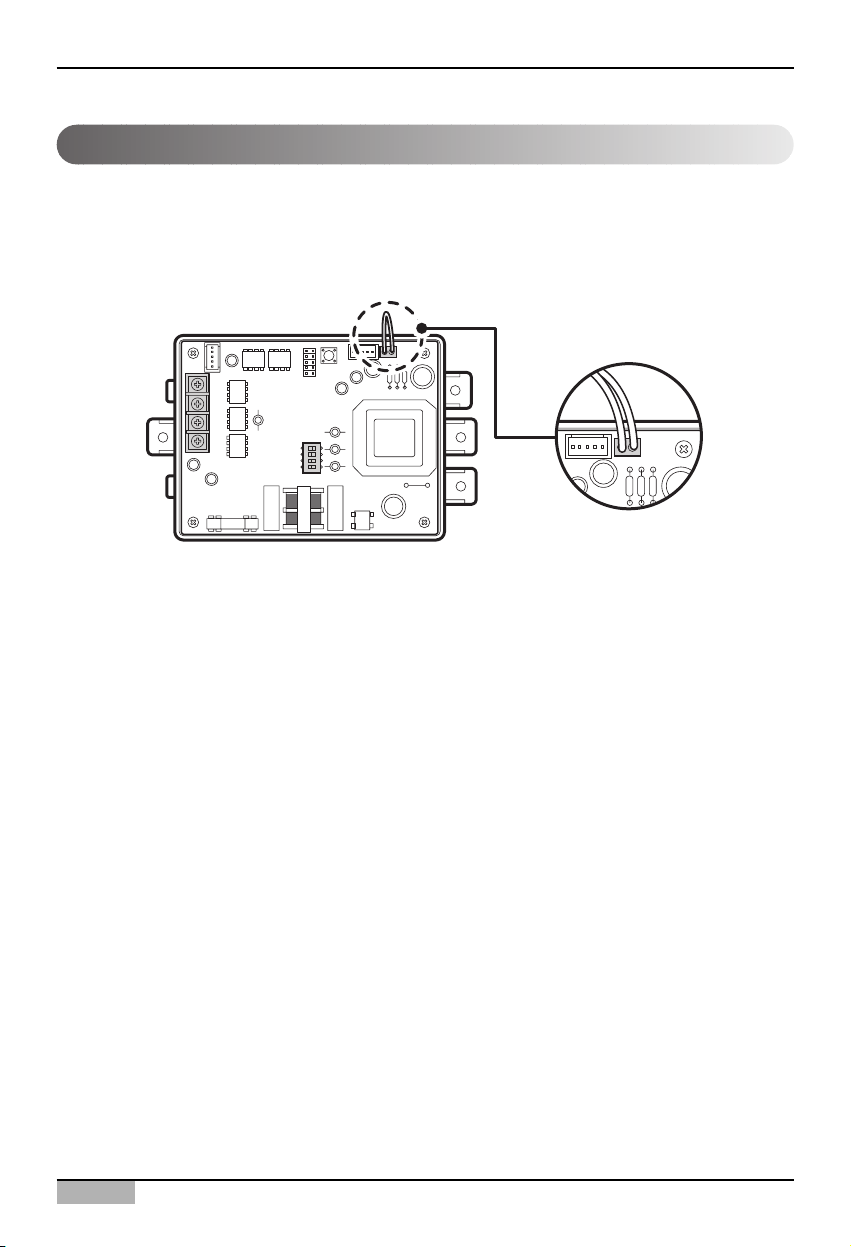
Connecting the 2PIN connector
If you want to use the individual lock function for setting mode, wind flow, and temperature lock by the
central control, the 2PIN connector should be connected to the CN_DRY terminal of the PI485
according to the product type.
ON
L1 2 3 4
KSDO4H
Installation/Owner's Manual
2-15
2. Installing ACP
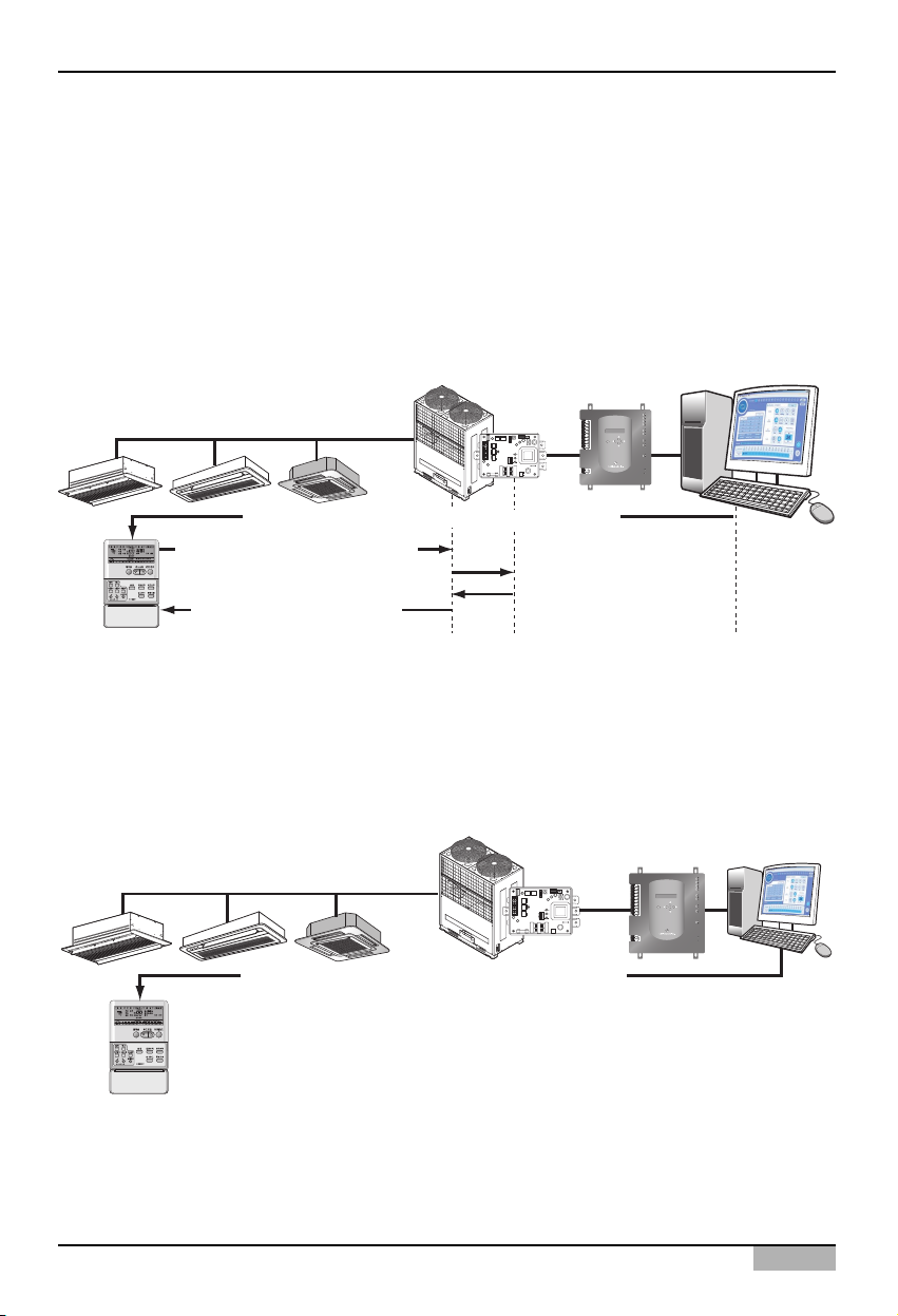
The following figure shows the example of the central control for connecting the 2PIN connector to the
CN_DRY terminal.
1) 'Heating operation, 20°C , Strong wind, Temperature lock' function is ordered by the central control
such as ACP or AC Manager, which is transferred to the remote controller.
2) If the user changes the temperature to 25°C by the remote controller, the related command is
transferred to the outdoor unit and the remote controller displays the 25°C setting.
3) The outdoor unit receives the related command and transferrs it to the PI485.
4)
The PI485 cancels this command and transferrs the previous central control command again. And, the
remote controller displays again the 20°C temperature transferred by the central control command.
On the other hand, let's see an example of connecting the 2PIN connector to CN_DRY terminal.
When a command is given for function of "Heat operation, 20°C setting, high fan level, temperature
lock" through the central control, the applicable command is transmitted through the remote
controller. "HL (Hard Lock)" message showing the central control status is displayed on the remote
controller. If the user sets the temperature to 25°C, the command is blocked at the remote controller.
Multi V
TX
LG-NET 1
RX
TX
LG-NET 2
RX
1
DI
TX
LG-NET 3
2
RX
3
TX
4
LG-NET 4
RX
5
6
7
TX
8
FDD
RX
9
TX
10
Ext.
RX
11
12
13
14
ACT
Ethernet 1
15
LNK
16
MENU/
17
ACT
Ethernet 2
18
SELECT
LNK
19
20
TX
Console
RX
1
Run
DO
2
3
Power
4
ACP
1) Set ‘Heating, 20°C, Strong wind, Temperature lock’
2) Change temperature to 25°C
3) Heating, 25°C, Strong wind
5) Heating, 20°C, Strong wind
6) Return to Heating, 20°C, Strong wind
ON
L1 2 3 4
KSDO4H
4) Heating, 20°C, Strong wind
Multi V
TX
LG-NET 1
RX
TX
LG-NET 2
RX
1
DI
TX
LG-NET 3
2
RX
3
TX
4
LG-NET 4
RX
5
6
7
TX
8
FDD
RX
9
TX
10
Ext.
RX
11
12
13
14
ACT
Ethernet 1
15
LNK
16
MENU/
17
ACT
Ethernet 2
18
SELECT
ON
L1 2 3 4
KSDO4H
LNK
19
20
TX
Console
RX
1
Run
DO
2
3
Power
4
Set ‘Heating, 20°C, Strong wind, Temperature lock’
The remote controller displays ‘HL’ message
It is not possible for the user to operate.
ACP
2-16
2. Installing ACP
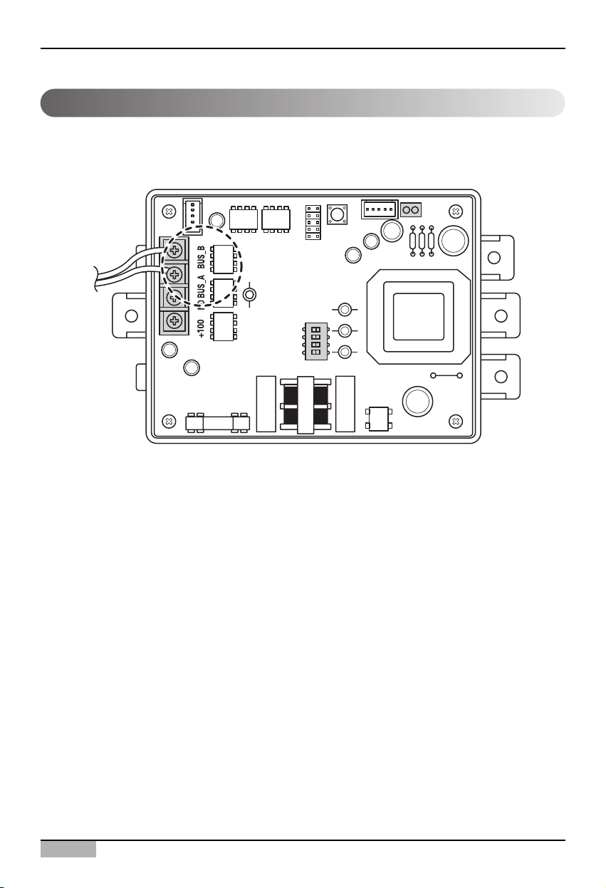
Connceting RS485 cable to PI485
In order to connect the PI485 and the ACP, two RS485 cables should be connected to the BUS_A and
the BUS_B of the PI485. Connect the RS485 cables by referring to the following figure.
When connecting more than one PI485 to one ACP, connect the BUS_A/BUS_B of the PI485 to the
BUS_A/BUS_B of the other PI485 respectively.
ON
L1 2 3 4
KSDO4H
 Loading...