

LG PHLTB INSTALLATION MANUAL
P/NO : MFL65222201
INSTALLATION MANUAL
AIR
CONDITIONER
www.lg.com
Please read this installation manual completely before installing the product.
Installation work must be performed in accordance with the national wiring
standards by authorized personnel only.
Please retain this installation manual for future reference after reading it
thoroughly.
(Sanitary Water Tank Kit)
PHLTB
Safety Precautions
To prevent injury to the user or other people and property damage, the following instructions must be followed.
Be sure to read before installing the unit.
Be sure to observe the cautions specified here as they include important items related to safety.
Incorrect operation due to ignoring instruction will cause harm or damage. The seriousness is classified
by the following indications.
This symbol indicates the possibility of death or serious injury.
This symbol indicates the possibility of injury or damage to properties only.
For antifreeze, always contact the dealer or an
authorized service center.
•
Almost the antifreeze is a toxic product.
Do not modify or extend the
power cable.
• There is risk of fire or electric shock.
Do not install, remove, or
reinstall the unit by yourself
(customer).
• There is risk of fire, electric shock,
explosion, or injury.
Be cautious when unpacking
and installing the unit.
•
Sharp edges could cause injury. Especially careful
on the unit edges and the fins on the heat exchanger.
Install the panel and the cover
of control box securely.
• There is risk of fire or electric shock.
Always install a dedicated
circuit and breaker.
• Improper wiring or installation may
cause fire or electric shock.
Use the correctly rated breaker
or fuse.
• There is risk of fire or electric.
Do not use a defective or underrated
circuit breaker. Use this appliance on
a dedicated circuit.
• There is risk of fire or electric shock.
For electrical work, contact the
dealer, seller, a qualified electrician,
or an Authorized Service Center.
• There is risk of fire or electric shock.
Always ground the unit.
• There is risk of fire or electric shock.
Be sure the installation area does not
deteriorate with age.
• If the base collapses, the unit could fall with it, causing
property damage, unit failure, and personal injury.
Keep level even when installing the unit.
• To avoid vibration or water leakage.
Use two or more people to lift and transport the
unit.
• Avoid personal injury.
For installation, always contact the dealer or an
Authorized Service Center.
Do not install the unit on a defective installation
stand.
• There is risk of fire, electric shock, explosion, or injury. • It may cause injury, accident, or damage to the unit.
2
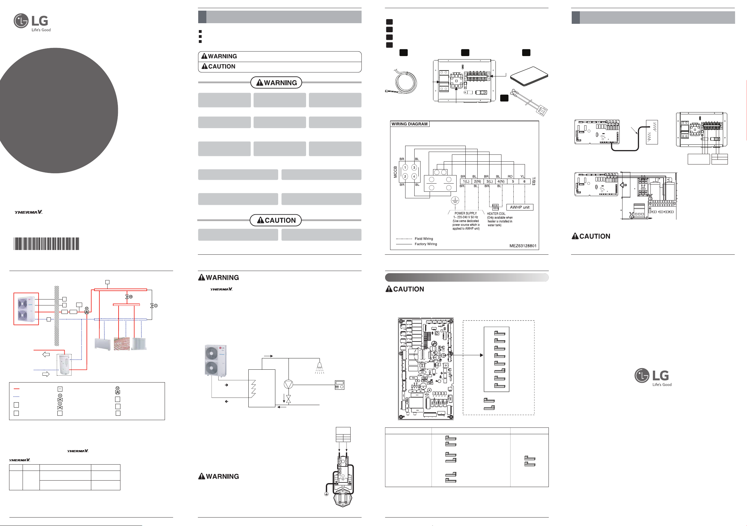
Parts
4
Installation Method
How to Install Sanitary Water Tank Kit
Follow below procedures Step 1 ~ Step 5.
To establish sanitary water circuit, 3way valve and sanitary water tank kit is required.
Step 1. Uncover the water tank kit and locate it on the wall.
Step 2. Connect the water tank kit to the main power like the below figure 2.
Step 3. Connect the water tank kit to the Main PCB Assembly1 like the below figure 2.
Step 4.
Connect power cord of sanitary tank heater. It is located inside of the tank. Refer to the next
page for more information.
Step 5.
Find sanitary water tank sensor
Step 6.
Connect the Main PCB to terminal block with wire(Part 4) like figure 3.
※ This wire is only for AHBWXXXA0 model.
. Plug it to 'CN_TH4' (Red Connector) of the main PCB
assembly 1.
Like below figure. 1
The sensor should be mounted correctly to the sensor hole of sanitary water tank.
Sensor mounting
Insert sensor into sensor socket and bolt it tightly
Sanitary Water
Tank
Sanitary
Sensor
CN-TH4
Main Power
220-240
67
BR
Main PCB
BL
Fig. 1
Fig. 2
.
Fig. 3
Water Tank
CH-B/HEAT(A)
5
Connecting Sanitary Water Tank
R
T
Outdoor Indoor
Floor heating loopFan coil unit
Sanitary
water
tank
Hot water
City water
Radiator
A
E/T
E/H
S
W/P
High Temperature
Room Thermostat(Field supply)
2way valve
(Field supply)
3way valve
(Field supply)
By-pass valve(Field supply)
Low Temperature
Expansion Tank
(Field supply)
Air Vent
Strainer(Mesh : 1mm*1mm)
Remote Controller
E/T
Electric Heater
E/H
Water Pump
(Field supply)
W/P
A
S
R
Note:
• Sanitary water tank
- It should be equipped with internal electric heater to generate sufficient heat energy in very cold
season.
supports following 3way valve.
(1) : SPDT = Single Pole Double Throw. Three wires consist of Live1 (for selecting Flow A), Live 2
(for selecting Flow B), and Neutral (for common).
(2) : Flow A means ʻwater flow from the unit to under floor water circuit.ʼ
(3) : Flow B means ʻwater flow from the unit to sanitary water tank.ʼ
YesSelecting “Flow B” between
“Flow A” and “Flow B” (3)
YesSelecting “Flow A” between
“Flow A” and “Flow B” (2)
1~ 230 VSPDT
3-wire
(1)
SupportedOperating ModePowerType
• 3way valve
- Refer to the installation manual of to install the 3way valve.
DIP Switch Setting
Turn off electric power supply before setting DIP switch.
• Whenever adjusting DIP switch, turn off electric power supply to avoid electric shock.
General Information
OFF ON
1
2
3
4
5
6
7
8
OFF is selected
ON is selected
Description Setting Default
Accessory installation
information.
2
3
Unit only
2
3
Unit + Sanitary water tank
is installed.
2
3
Unit + Sanitary water tank
+ Solar thermal system
is installed.
2
3
7
6
Installing recirculation pump
When is used with sanitary water tank, it is STRONGLY recommended to install recirculation
pump to prevent flooding out cold water at the end of hot water supply and to stabilize the water temperature
inside the sanitary water tank.
- The recirculation pump should be operated when sanitary water demand is not required. Therefore, external
time scheduler to determine when the recirculation pump should turn on and turn off is required.
- The operating duration time of the recirculation pump is calculated as follow :
Duration time [minute] = (k*V)/R
k : 1.2 ~ 1.5 is recommended. (If distance between pump and tank is far, then choose high number.)
V : Volume of sanitary water tank [liter]
R : Water flow rate of pump [liter per minute], which is determined by pump performance curve.
- The pump operating start time should be prior to the sanitary water demand.
Sanitary
Water Tank
Recirculation
Pump
External
Time Scheduler
Check Valve
Shower
(End of Hot
water supply)
Hot water supply
City water
Water In
Water Out
How to Wire Sanitary Water Tank Heater
Step 1. Uncover heater cover of the sanitary water tank. Heater is located
inside of the tank.
Step 2. Find terminal block in the water tank kit and connect wires as below.
Wires are field-supplied item.
(L) : Live signal from Water Tank Kit to Heater
(N) : Neutral signal from Water Tank Kit to Heater
(L) (N)
A
Terminal block
in the water
tank kit
BR BL
L43N
Fig. 3
Wire specification
• Cross-sectional area of the wire should be over 5mm2.
• You should use the shield wire for the signal wire in terminal block 5,6 not
to make the electric noise.
Adjusting thermostat temperature
• To guarantee proper operation, it is recommended to set temperature of
thermostat to maximum temperature (symbol
ʶ
at the figure 3).
Sensor (Thermistor)
1
Water tank kit
2
Installation Manual
3
Multi harness (only AHBWXXXA0 model use)
4
1 2 3
MCCB
Magnetic switch
YL RD
A1 A2
Magnet switch
contact
BL
L3
T3
BL
Wiring Diagram
BR
L1
T1
BR
Terminal
Block 3
4
3
 Loading...