

Page 1
Installation Manual
for LG CO2 Sensor
Model Number: PESC0RV0
Page 2

PROPRIETARY DATA NOTICE
This document, as well as all reports, illustrations, data, information, and other materials are the property of
LG Electronics U.S.A., Inc., and are disclosed by LG Electronics U.S.A., Inc. only in confidence.
Do not throw away, destroy, or lose this manual.
Please read carefully and store in a safe place for future reference.
Content familiarity required for proper installation.
The instructions included in this manual must be followed to prevent product malfunction, property damage, injury, or death to the user or
other people. Incorrect operation due to ignoring any instructions will cause harm or damage. The level of seriousness is classified by the
symbols described by the summary list of safety precautions on page 3.
For more materials such as submittals, catalogs, engineering,
installation, owner’s, and service manuals, visit www.lghvac.com.
For continual product development, LG Electronics U.S.A., Inc. reserves the right to change specifications without notice.
© LG Electronics U.S.A., Inc.
Page 3
DANGER
CAUTION
SAFETY PRECAUTIONS
The instructions below must be followed to prevent product malfunction, property damage, injury or death to the user or other people. Incorrect operation due to ignoring any instructions will cause harm or damage. The level of seriousness is classified by the symbols described
below.
TABLE OF SYMBOLS
This symbol indicates an imminently hazardous situation which, if not avoided, will result in death or serious injury.
This symbol indicates a potentially hazardous situation which, if not avoided, could result in death or serious injury.
This symbol indicates a potentially hazardous situation which, if not avoided, may result in minor or moderate injury.
This symbol indicates situations that may result in equipment or property damage accidents only.
This symbol indicates an action should not be completed.
INSTALLATION
All electrical work must be performed by a licensed electrician and conform to local building codes or, in the absence
of local codes, with the National Electrical Code, and the
instructions given in this manual.
If the power source capacity is inadequate or the electric
work is not performed properly, it may result in re, electric
shock, physical injury or death.
Do not touch the CO2 sensor’s PCB, any exposed wiring, terminals, or other electrical components with tools or exposed
skin when the power is connected. Only qualied technicians
should install, remove, or re-install the sensor.
Improper installation or use may result in re, electric shock, physical
injury or death.
Do not install, remove, or re-install the unit by yourself (end
user). Ask the dealer or an authorized technician to install the
unit.
Improper installation by the user may result in re, electric shock, physical injury or death.
For replacement of an installed sensor, always contact an
authorized LG service provider.
There is risk of re, electric shock, and physical injury or death.
Do not install the sensor in a highly humid environment or
where it can be exposed to rain.
There is risk of physical injury or death due to electric shock.
Safely dispose of the packing materials.
Tear apart and throw away plastic packaging bags so that children may
not play with them and risk suffocation and death.
Safety Precautions
Only qualied technicians should install, remove, or re-install
the sensor.
Improper installation or use may result in product malfunction.
Do not install the sensor in a highly humid environment or
where it can be exposed to rain.
There is risk of product malfunction.
Due to our policy of continuous product innovation, some specifications may change without notification.
©LG Electronics U.S.A., Inc., Englewood Cliffs, NJ. All rights reserved. “LG” is a registered trademark of LG Corp.
Do not drop the sensor.
It may damage the case.
3
Page 4

DANGER
CAUTION
SAFETY PRECAUTIONS
OPERATION
Do not provide power to or operate the sensor if it is ooded
or submerged. Always have the dealer or an authorized technician to service the sensor.
There is risk of re, electric shock, physical injury or death.
Do not install the CO2 sensor (or its hard-wired and exten-
sion cables) in a location exposed to open ame or extreme
heat. Do not touch the sensor with wet hands.
There is risk of re, electric shock, physical injury or death.
Only authorized persons should operate the product.
If the sensor is not operated properly, there is a risk of physical injury.
Do not store or use ammable gas or combustibles near the
sensor.
There is risk of re, explosion, and physical injury or death.
Do not modify or extend the power supply cord.
There is risk of re, electric shock, physical injury or death.
Sensor Installation Manual
Do not the sensor to get wet.
2
There is risk of unit failure or malfunction.
CO
Only authorized persons should operate the CO2 sensor.
There is risk of unit failure or malfunction.
Do not drop the CO2 sensor.
There is risk of unit failure or malfunction.
4
Due to our policy of continuous product innovation, some specifications may change without notification.
©LG Electronics U.S.A., Inc., Englewood Cliffs, NJ. All rights reserved. “LG” is a registered trademark of LG Corp.
Page 5

INTRODUCTION, PARTS LIST, AND
SPECIFICATIONS
Introduction
The CO2 sensor is especially designed to work in conjunction with LG Energy Recovery Ventilators (ERVs). Real-time CO2 levels are detected and displayed on the sensor’s LCD. The CO2 sensor then sends the data to the LG ERV via the hard-wired connection cable coupled with
the supplied 33-foot extension cable. LG ERVs, using stand-alone embedded logic, will respond to CO2 changes in the surrounding ambient
air by applying demand control ventilation when its fan is set to Auto mode. Energy efficiency is increased, and indoor air quality can be
improved when ventilation air is introduced to the monitored space only as necessary.
The CO2 sensor does not work with interlock or slave operation with indoor units.
Factory-Supplied Parts
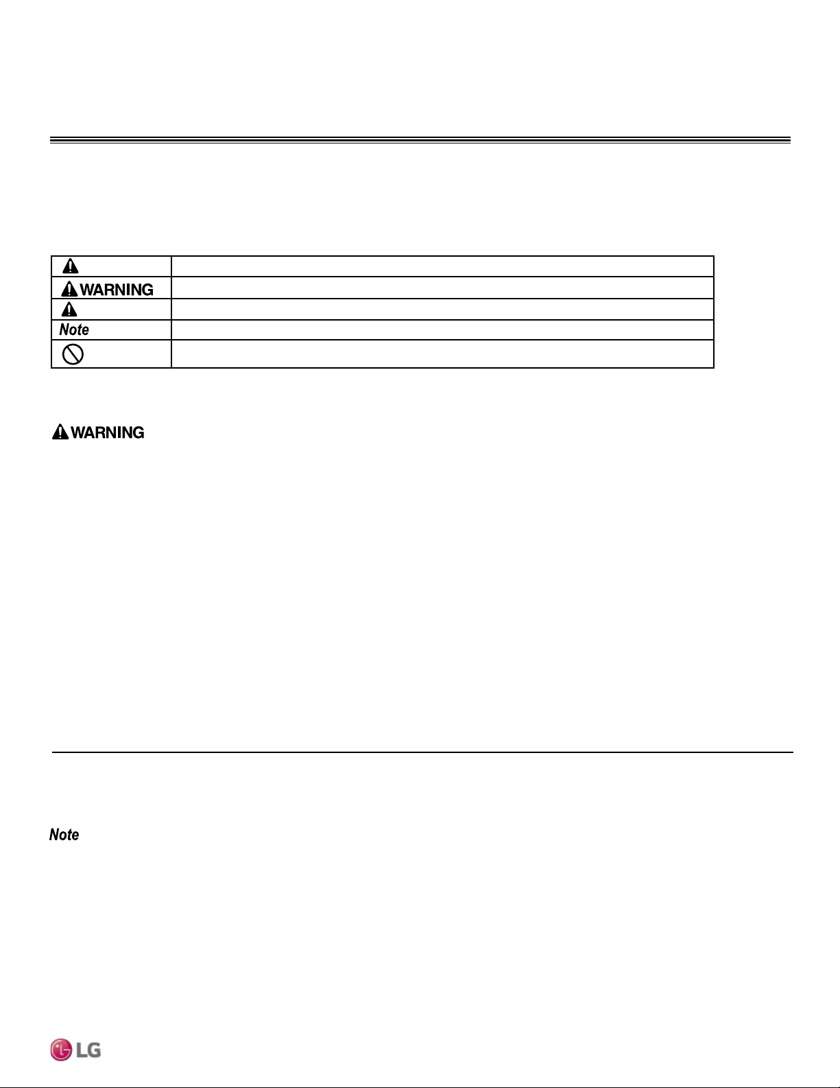
Figure 1: CO2 Sensor (Model No. PES-C0RV0).
6-inch Hard-Wired
Connection Cable
Table 1: Factory-Supplied Parts Table.
Part Quantity Image
LCD
Yellow
LED
CO2 Sensor
33-foot Extension
Cable
Mounting Screws Three (3)
Installation Manual One (1)
Specifications
Table 2: Specications Table.
Specications
For Use With ARVU053-063ZEA2 and ARVU093-123ZFA2 LG Energy Recovery Ventilators (ERV)
Power Supply 12V DC ±5%
Analog Output 0 to 5V DC
Measuring Range 0 to 2,000 ppm
Dimensions 4-1/16″ H x 3-1/4″ W x 1-1/4″ D
Net Weight 4 oz. (CO2 Sensor with its 6-inch Hard-Wired Cable Only)
Shipping Weight Approximately 1 lb.
One (1)
Installation
Due to our policy of continuous product innovation, some specications may change without notication.
©LG Electronics U.S.A., Inc., Englewood Cliffs, NJ. All rights reserved. “LG” is a registered trademark of LG Corp.
5
Page 6

INSTALLATION AND WIRING
1. Open the Case.
To open CO2 sensor case, insert a flat-head screwdriver in the slot (see right), and gently twist.
2. Remove the CO2 sensor Printed Circuit Board (PCB).
The installer needs to remove the PCB attached to the bottom part of the case before
wall-mounting the CO2 sensor. To detach, push the support tabs out that are holding the PCB, lift
the PCB up, and remove.
To avoid damaging the CO2 sensor PCB, place it in a clean secure
location while the backplate is being installed.
Figure 3: Push the Support Tabs Out.
3. Choose an installation location for the CO2 sensor.
General Dos
The CO2 sensor should be installed:
• In an occupied space that has air exchange from the ERV
• Where it can accurately detect the CO2 level of the space
• Four (4) to five (5) feet above the floor where its LED display can
be read easily (if CO2 sensor monitoring is required; possibly near
the zone controller)
• In an area with good air circulation
• Where the CO2 sensor is within reach of the ERV with the one (1) factory-supplied 33-foot extension
cable
To detach the PCB from the
bottom cover, push the support
tabs out.
Figure 2: Removing the Cover.
Figure 4: Attaching the CO2
Sensor Case to the
Wall.
General Don’ts
Do not install the CO2 sensor near or in:
• Drafts or dead spots behind doors and in corners
Sensor Installation Manual
2
• An open window
4. Wall-mount the CO2 sensor.
LG CO
Using the bottom part of the case as a template, mark the area on the wall where the three (3) factory-supplied screws and the access hole for the hard-wired connection cable should go. Drill the holes,
then attach the bottom of the CO2 sensor case securely to the wall.
Holes for the Three (3) Screws
5. Reinsert the PCB and reattach the cover.
After wiring is complete (see Wiring), place the right side of the PCB under the guides on the case. Gently push the left side of the PCB
under the support tabs until it snaps in place, indicating it is secure.
Position the three guides (on the cover) at the bottom of the case, then push down on the top until the two hooks snap in place.
Figure 5: CO2 Sensor PCB.
Wiring
The CO2 sensor PCB has a hard-wired connection cable ending in a female terminal. The factory-supplied 33-foot male extension cable connects this cable to the CN-CO2 terminal on the ERV PCB. No
splicing or additional connections are required.
6
Due to our policy of continuous product innovation, some specications may change without notication.
©LG Electronics U.S.A., Inc., Englewood Cliffs, NJ. All rights reserved. “LG” is a registered trademark of LG Corp.
Page 7

WIRING PROCEDURE, OPERATION,
+
+
33-Foot Extension Wire
CO2 Sensor
*
ERV PCB Example
(Actual Appearance Depends on Model)
CN-CO2
AND TROUBLESHOOTING
Wiring Procedure
1. Power down the ERV.
2. Attach one male end of the extension cable to the female connection on the hard-wired cable.
3. Attach the other male end of the extension cable to the CN-CO2 terminal on the ERV Main PCB.
4. Reattach the CO2 sensor PCB to the bottom of the case (that has already been wall-mounted).
Figure 6: Wiring from ERV PCB to CO2 Sensor.
Use only the hard-wired factory supplied 33-foot extension wire.
Field-supplied wires and / or splicing is not / are not permitted.
There is risk of unit failure or malfunction if cables other than LG
supplied components are used.
Operation
1. At initial power up, a wrench symbol will appear on the LCD and the yellow LED on
the CO2 sensor PCB lights up for two (2) to three (3) seconds.
2. Turn ERV on at the zone controller or central controller. Set the ERV fan mode to Auto.
3. The ambient CO2 concentration in parts per million (ppm) will then appear on the
LCD. Permit the system to operate for about five [5] minutes before obtaining an
accurate reading.
4. The CO2 reading will update every three (3) seconds, using data from the CO2
infrared sensor.
5. ERV fans will automatically operate according to CO2 sensor readings (see table at right).
Table 3: ERV Operation Sequence with CO2 Sensor.
CO2 Sensor Reading ERV Fan Operation
<500 ppm Off
500-700 ppm Low Speed
700-900 ppm High Speed
>900 ppm Super High Speed
Troubleshooting
• The wrench symbol displays on the LCD and the yellow LED on the CO2 sensor PCB turns on if there is an error and / or if the reading is
outside the measuring range (0 to 2,000 ppm).
• Both the wrench symbol and the yellow LED will turn off when the CO2 sensor returns to normal operation.
• If CO2 readings fluctuate ±200 ppm, the reading may be unstable.
• If the system has been operating for more than five (5) minutes, and readings continue to be unstable, verify that the CO2 sensor’s
connections are properly secured.
Installation
Due to our policy of continuous product innovation, some specications may change without notication.
©LG Electronics U.S.A., Inc., Englewood Cliffs, NJ. All rights reserved. “LG” is a registered trademark of LG Corp.
7
Page 8

Contact your local sales representative if you have any
questions about the CO2 sensor or its installation.
LG Electronics, U.S.A., Inc.
Commercial Air Conditioning Division
11405 Old Roswell Road
Alpharetta, Georgia 30009
www.lg-vrf.com
LG Customer Information Center, Commercial Products
1-888-865-3026 USA
Follow the prompts for commercial A/C products.
IM-CO2-Sensor-PESC0RV0-3-15
 Loading...