

Page 1

LG
Weekly Wired Remote Controller
LG
IMPORTANT
• Please read this installation manual completely
before installing the product.
• Installation work must be performed in
accordance with the national wiring standards
by authorized personnel only.
• Please retain this installation manual for future
reference after reading it thoroughly.
Owner's & Installation Manual
Models: PCRCUSZ0
PDRCUSZ0
Page 2

2 Weekly Wired Remote Controller
Weekly Wired Remote Controller Owner’s & Installation Manual
TABLE OF CONTENTS
■ Safety Precaution .............................................................................................3~4
■ Part Description................................................................................................5~8
■ Installation instruction .........................................................................................9
■ Remote controller connection method.............................................................10
■ Address setup of central control ......................................................................11
■ E.S.P(DUCT TYPE)..............................................................................................12
■ Cooling operation.........................................................................................13~14
Standard cooling ................................................................................................13
Power cooling .....................................................................................................14
■ Heating operation ...............................................................................................15
■ Temperature control...........................................................................................16
Setting desired temperature................................................................................16
The room temperature confirmation....................................................................16
■ Fan Speed operation .........................................................................................17
Fan Speed selector.............................................................................................17
Air flow direction control......................................................................................17
■ Additional functions.....................................................................................18~28
Auto operation.....................................................................................................18
Dehumidification operation .................................................................................19
Fan operation .....................................................................................................19
Plasma................................................................................................................19
Swirl Function......................................................................................................20
Heater .................................................................................................................20
Ventilation ...........................................................................................................21
Humidifier............................................................................................................22
Fan Auto..............................................................................................................22
Vane control........................................................................................................23
Setting current time ............................................................................................24
Setting preset for weekly time.............................................................................25
Setting holiday.....................................................................................................26
On preset ............................................................................................................27
Off preset ............................................................................................................27
Usage restriction function....................................................................................28
Auto restarting Function .....................................................................................28
Self diagnosis fuction .........................................................................................28
Different mode operation.....................................................................................29
Page 3
Safety Precaution
Owner’s & Installation Manual 3
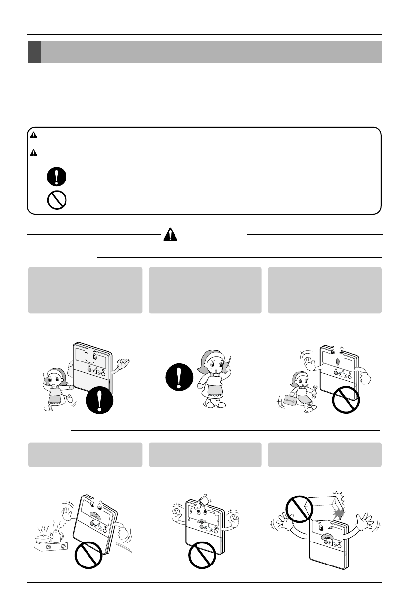
Be sure to request to the
service center or installation
specialty store when
installing products.
• It will cause fire or electric shock
or explosion or injury.
Request to the service center
or installation specialty store
when reinstalling the
installed product.
• It will cause fire or electric shock
or explosion or injury.
Do not disassemble, fix, and
modify products randomly.
• It will cause fire or electric shock.
Do not place flammable
stuffs close to the product.
• It will cause fire.
Do not allow water to run
into the product.
• It will cause electric shock or
breakdown.
Do not give the shock to the
product.
• It will cause breakdown when
giving the shock to the product.
■ Installation
Safety Precaution
• The installation requires expert skills, and it should be installed by the service center or other shops specialized
in the installation and recognized by our company.
• For all the problems arising after installation by someone who has no relevant qualifications, our company will
not provide free service.
• The following safety cautions are provided to prevent unexpected dangers or losses.
: If the user does not follow the mandatory items, it may result in serious injury or death.
: If the user does not follow the mandatory items, it may cause personal injury or property
damage.
: Warning and Caution are to call the user’s attention to the possible danger. Read and follow
them carefully in order to prevent a safety accident.
: Warning and Caution are indicated in this guide and the product itself to help protect the users
from danger.
WARNING
CAUTION
WARNING
■ In-use
AUTO SWING
OPERATION
SET TEMP
Ro
o
m T
FAN SPEED
e
m
p
SUB FUNCTION
T
i
H
m
I
e
r
On
A
Oper
U
Off
TO
M
a
E
t
D
ion unit
Hea
Set
t
no.
T
er
im
T
P
i
e
m
r
L
ehea
e
O
Defro
01
t
JET
s
P
t
r
03
o
Hum
g
r
a
m
ZONE
Filter
i
dify
05
s
et
07
Out do
09
o
r
1
1
2
1
3
1
4
315
17
19
2
1
2
3
A
U
TO SWING
OPERATION
SET TE
T
Ro
im
M
o
On
P
e
m T
r
e
m
Off
Set no.
p
Oper
FAN SPE
a
t
ion unit
T
im
e
E
01
D
HI
T
03
SUB FUNCTION
im
M
A
E
e
UTO
D
P
05
r
o
g
LO
Heater
r
a
m set
07
JET
Defrost
Preheat
09
ZONE
Filter
11
Humidify
13
Out door
1
15
2
3
17
4
19
21
23
AUTO SWING
OPERATION
SET TEMP
Ro
o
m T
FAN SPEED
e
m
p
SUB FUNCTION
T
i
H
m
I
e
r
On
A
Oper
U
Off
TO
M
a
E
t
D
ion unit
Hea
Set
t
no.
T
er
im
T
P
i
e
m
reheat
L
e
O
Defr
01
JET
o
s
P
t
r
03
o
Hum
g
r
a
m
ZONE
Filter
i
dify
05
s
et
07
Out do
09
o
r
1
1
2
1
3
1
4
315
17
19
2
1
2
3
AUTO SWING
OPERATION
SET TEMP
Ro
o
m T
FAN SPEED
e
m
p
SUB FUNCTION
T
im
H
I
e
r
On
A
Oper
U
Off
TO
M
a
E
t
D
ion unit
Hea
Set
t
no.
T
er
im
T
P
i
e
m
r
L
ehea
e
O
Defro
01
t
JET
s
P
t
r
03
o
Hum
g
r
a
m
ZONE
Filter
i
dify
05
s
et
07
Out do
09
o
r
1
1
2
1
3
1
4
315
17
19
2
1
2
3
AUTO SWING
OPERATION
SET TEMP
Ro
o
m T
FAN SPEED
e
m
p
SUB FUNCTION
T
i
H
m
I
e
r
On
A
Oper
U
Off
TO
M
a
E
t
D
ion unit
Hea
Set
ter
no.
T
im
T
P
i
e
m
r
L
ehea
e
O
Defro
01
t
JET
s
P
t
r
03
o
Hum
g
r
a
m
ZONE
Filter
i
dify
05
s
et
07
Out do
09
o
r
1
1
2
1
3
1
4
3
15
17
19
2
1
2
3
Page 4
Safety Precaution
4 Weekly Wired Remote Controller
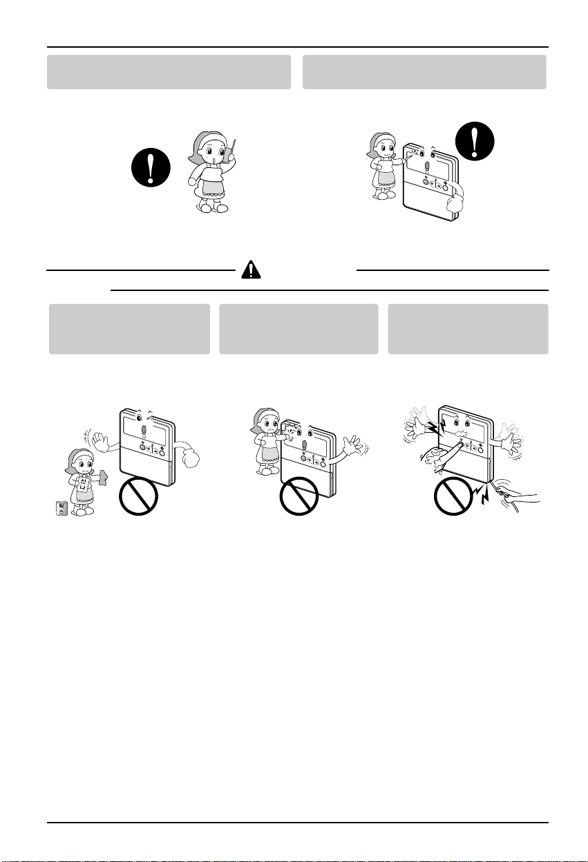
■ In-use
CAUTION
Request to the service center or installation
specialty store when the product becomes wet.
• It will cause fire or electric shock.
Do not give the shock using sharp and
pointed objects.
• It will cause breakdown by damaging parts.
Do not clean using the
powerful detergent like
solvent but use soft cloths.
• It will cause fire or product
deformation.
Do not press the screen
using powerful pressure or
select two buttons.
• It will cause product breakdown or
malfunction.
Do not touch or pull the lead
wire with wet hands.
• It will cause product breakdown or
electric shock.
H
I
M
E
D
L
O
Z
O
N
E
1
2
3
4
T
im
e
P
r
o
g
r
a
m
s
e
t
T
i
m
e
r
O
n
S
e
t
n
o
.
T
i
m
e
O
ff
0
1
0
3
0
5
0
7
0
9
1
1
1
315
1
7
1
9
O
p
e
r
a
t
i
o
n
u
n
i
t
JE
T
H
e
a
te
r
D
e
fro
s
t
P
re
h
e
a
t
H
um
id
ify
F
ilte
r
O
u
t d
o
o
r
R
o
o
m
T
e
m
p
AUTO SWING
OPERATION
SET TEMP
FAN SPEED
S
U
B
F
U
N
C
T
I
O
N
A
U
T
O
2
1
2
3
AUTO SWING
OPERATION
SET TEMP
Ro
o
m T
FAN SPEED
e
m
p
SUB FUNCTION
T
i
H
m
I
e
r
On
A
Oper
U
Off
TO
M
a
E
t
D
ion unit
Hea
Set
ter
no.
T
im
T
P
i
e
m
r
L
ehea
e
O
Defro
01
t
JET
s
P
t
r
03
o
Hum
g
r
a
m
ZONE
Filter
i
dify
05
s
et
07
Out do
09
o
r
1
1
2
1
3
1
4
3
15
17
19
2
1
2
3
AUTO SWING
OPERATION
SET TEMP
Ro
o
m T
FAN SPEED
e
m
p
T
im
H
I
e
r
On
A
Oper
U
Off
M
a
E
t
D
ion unit
Set
no.
T
im
T
i
e
m
L
e
O
01
JET
P
r
03
o
g
r
a
m
ZONE
05
s
et
07
09
1
1
1
3
15
17
AUTO SWING
OPERATION
SET TEMP
Ro
o
m T
FAN SPEE
e
m
p
D
SUB FUNCTION
T
im
H
I
e
r
On
A
Oper
U
Off
TO
M
a
E
t
D
ion unit
Hea
Set
t
no.
T
er
im
T
P
i
e
m
r
L
ehea
e
O
Defro
01
t
JET
s
P
t
r
03
o
Hum
g
r
a
m
ZONE
Filter
i
dify
05
s
et
07
Out do
09
o
r
1
1
2
1
3
1
4
3
15
17
19
2
1
2
3
SUB FUNCTION
TO
Hea
t
er
P
r
ehea
Defro
t
s
t
Hum
Filter
i
dify
Out do
o
r
1
2
3
4
19
2
1
2
3
Page 5
Part Description
Owner’s & Installation Manual 5
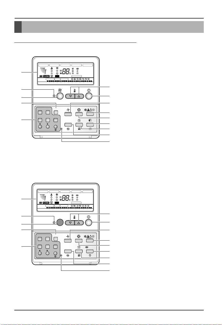
Part Description
Name and Function of Remote Controller
1. Operation indication screen
2. Swirl button
3. 2ndF button
4. Timer set/cancel
Program/Week/Holiday
Hour/Min/SET/Clr/Ventilator
5. Set temperature button
6. ON/OFF button
7. Fan operation
8. Operation mode selection button
9. Fan speed button
10. Horizontal/Vertical air flow
direction button
11. Room temperatur/filtersign
release button
12. Plasma/Heater button
13. Time reset button
14. Operation lamp
1. Operation indication screen
2. Wireless remote controller receiver
3. 2ndF button
4. Timer set/cancel
Program/Week/Holiday
Hour/Min/SET/Clr/Ventilator
5. Set temperature button
6. ON/OFF button
7. Fan operation
8. Operation mode selection button
9. Fan speed button
10. Fan auto/Humidification button
11. Room temperatur/filtersign
release button
12. Plasma/Heater button
13. Time reset button
14. Operation lamp
Timer
Program
Hour
Cancel 2ndF
Week Holiday
Set/Clr
Min
RESET
PLASMA
ZONE
1234
Operation unit
No Func
Humidify
JET
SLo
AUTO
AUTO SWING OPERATION
FAN SPEED
Program set
SUB FUNCTION
SET TEMP
Room Temp
HI
MED
LO
Heater
Defrost
Filter
Preheat
Out door
Time
Timer
On
Set no. Time
Off
01 03 05 07 09 11 13 15 17 19 21 23
2ndF
1
2
5
6
7
8
9
10
11
12
13
3
4
14
CST TYPE
Timer
Program
Hour
Cancel 2ndF
Week Holiday
Set/Clr
Min
RESET
PLASMA
AUTO
ZONE
1234
Operation unit
Humidify
JET
SLo
AUTO
AUTO SWING OPERATION
FAN SPEED
Program set
SUB FUNCTION
SET TEMP
Room Temp
HI
MED
LO
Heater
Defrost
Filter
Preheat
Out door
Time
Timer
On
Set no. Time
Off
01 03 05 07 09 11 13 15 17 19 21 23
2ndF
1
2
5
6
7
8
9
10
11
12
13
3
4
No Func
14
DUCT TYPE
❈ Operation lamp lights on during the indoor operation. If error occurs, the lamp lights on red color.
Page 6

Part Description
6 Weekly Wired Remote Controller
Accessory
Connection wire(1) Remote control lock
screw(5)
Operation/installation
Manual
Insulation
Page 7
Part Description
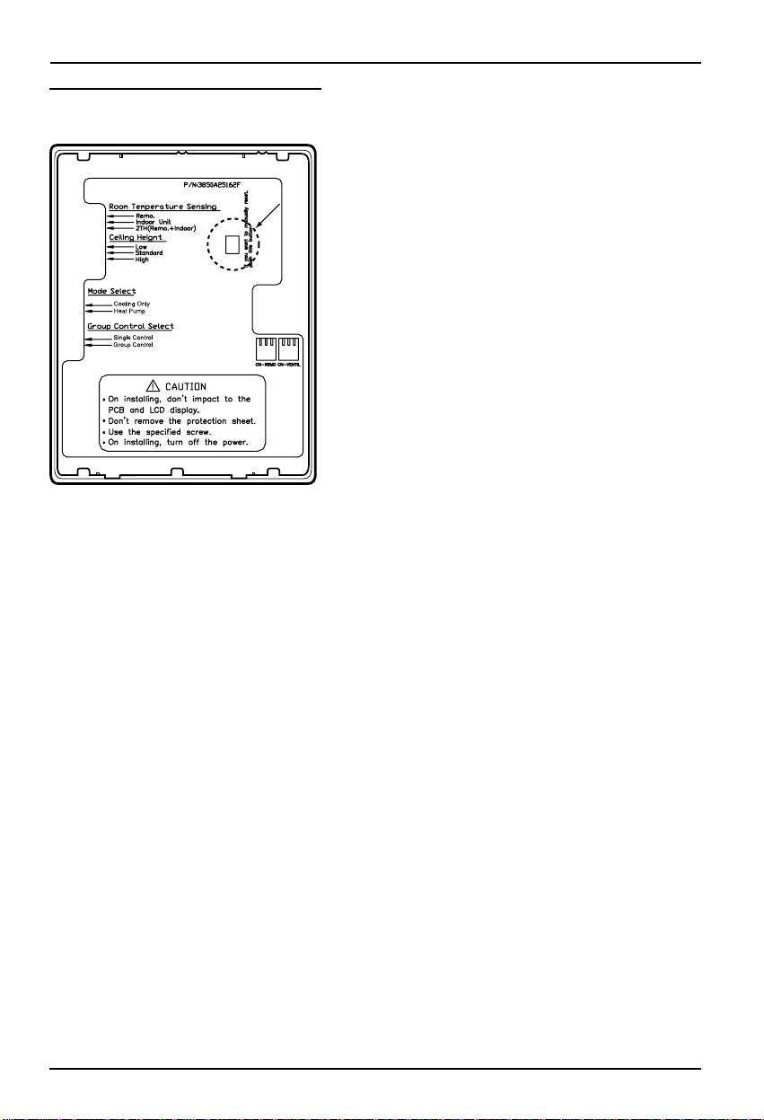
Owner’s & Installation Manual 7
Information of slide switch
CST TYPE
RESET switch
Room Temperature Sensing select
Switch
1. Use Remocon's sensor
2. Use Indoor's sensor
3. Use senor which has lower temrerature
between Remocon's and indoor's
Ceiling Height select switch
1. Low
2. Standard
3. High
Mode select switch
1. Cooling only
2. Heater pump
Group control select switch
1. Case of Single control
2. Case of Group control
* When changing the product selection switch and group control switch, you must press the reset switch to use
the changed selection.
RESET switch
RESET switch
Page 8
Part Description
8 Weekly Wired Remote Controller
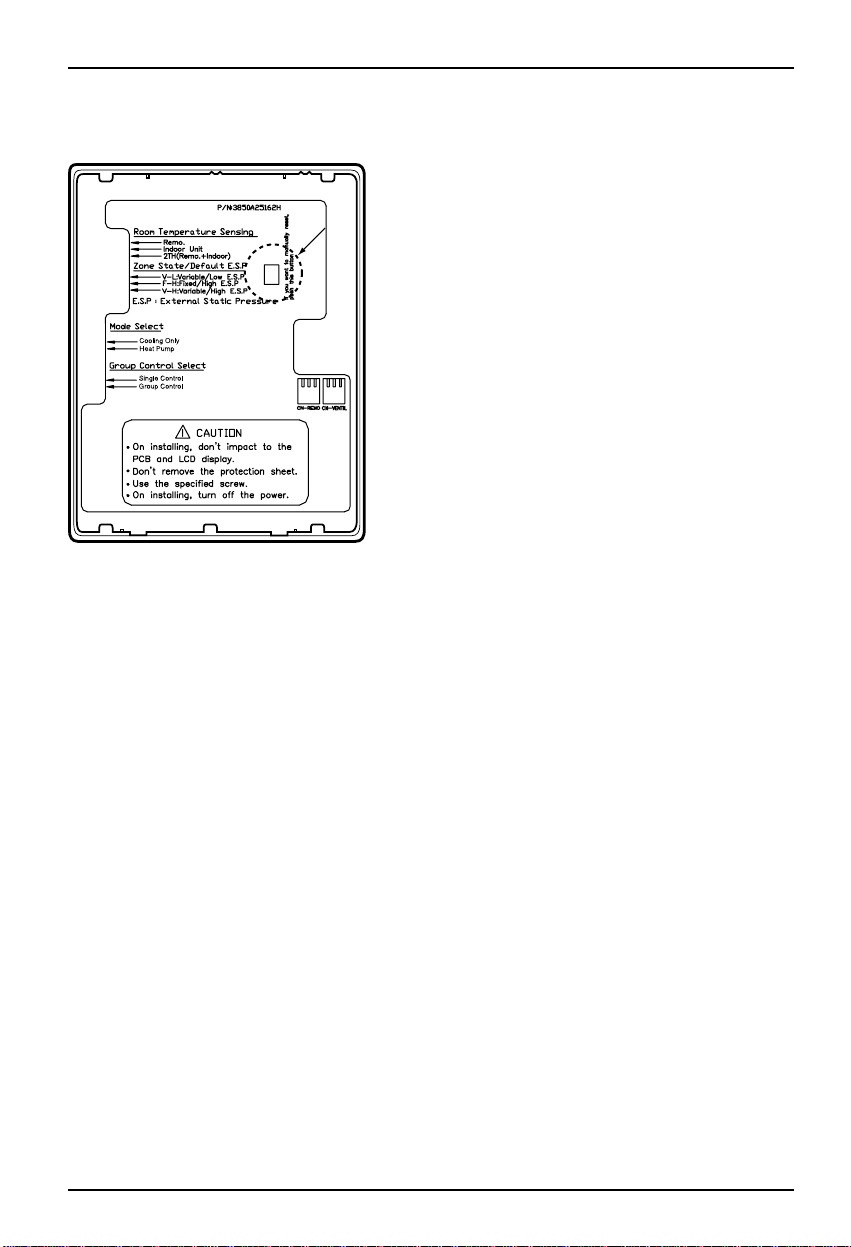
DUCT TYPE
RESET switch
Room Temperature Sensing select
Switch
1. Use Remocon's sensor
2. Use Indoor's sensor
3. Use senor which has lower temrerature
between Remocon's and indoor's
Zone State/Default E.S.P
1. Variable/Low E.S.P
2. Fixed/High E.S.P
3. Variable/High E.S.P
Mode select switch
1. Cooling only
2. Heater pump
Group control select switch
1. Case of Single control
2. Case of Group control
* When changing the product selection switch and group control switch, you must press the reset switch to use
the changed selection.
RESET switch
RESET switch
Page 9
Owner’s & Installation Manual 9
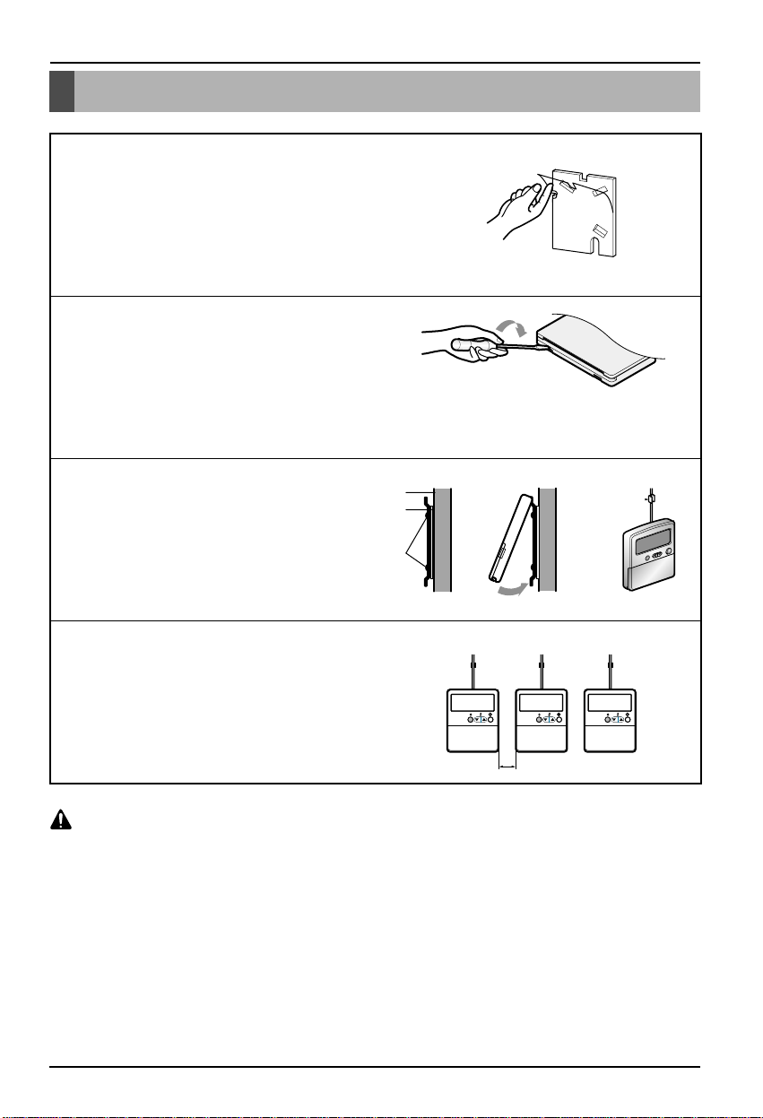
Installation instruction
Installation instruction
1
Remove the sticker that is attached on back of insulation and
attach the remote control on the wall you want to install.
2
Separate the cover of remote control like the right hand side.
3
Fix the setup board on top of the insulation.
4
Install each remote control with the distance of at least 2cm
between them when installing several wired remote controls
horizontally.
Before installing the wired remote controller, set the switch on the back of the wired remote controller
to the required condition of the product.
Especially, if the switch exclusively for air conditioning and air conditioning/heating selection switch is
incorrectly set, it can cause a problem to the product operation.
CAUTION
remote control
wall
insulation
lock screw
2cm
Page 10

Remote controller connection method
Remote controller connection method
10 Weekly Wired Remote Controller
1. Check the cable is conneced with CN-REMO
(CN-VENTIL is used if remocon is connected with ventilator)
2. Connect the cables between the indoor unit and the remote controller.
* When installing the wired remote controller, do not install it buried within the wall.
(It can cause problems to the temperature sensor.)
Do not install the cable for longer distance than 50m. (It can cause a communication error.)
When installing the cable, check the connector between the remote controller and the connector. The
connector will not be connected well when connected backwards.
CAUTION
Connector for the
remote controller side
Connector for the
indoor unit side
Page 11

Owner’s & Installation Manual 11
Address setup of central control
1
You can set the address up by pressing the Program
button and the Set/Clr button about 3 seconds at the
same time.
2
The group change uses the temperature control button
to change the value possibly. The number of indoor
unit uses the temperature control button to change the
value possibly.
Ex) Group address: 2
Indoor unit number: 3
3
You can complete setting up the address by pressing
the Program button and the Set/Clr button about 3
seconds at the same time.
• Multi model: Connect the outdoor unit and P1485 of outdoor unit
• Single model: Connect P1485 of outdoor unit
• When you connect the indoor unit with central control unit, you should setup Network address which is
recognized by central control unit inside of indoor unit.
• The address of central control is consisted by group number and number of indoor unit.
Note : The remote controller displays 'HL' if central controller has locked the remote controller.
Address setup of central control
AUTO SWING
OPERATION SET TEMP FAN SPEED
Room Temp
Time
Program set
Operation unit
Timer
On
Off
01 03 05 07 09 11 13 15 17 19 21
Time
Set no.
Cancel 2ndF
Timer
Program
Week Holiday
Hour
Min
Set/Clr
PLASMA
RESET
HI
MED
LO
ZONE
AUTO
JET
Heater
Defrost
Filter Out door
SUB FUNCTION
Preheat
Humidify
1234
23
Page 12

E.S.P(DUCT TYPE)
1
If you press the Timer button and the Fan Speed
button simultaneously for about 3 seconds, you can
enter the ESP value setting mode.
2
Using the Temperature Adjustment button, set the
ESP value for each wind level (Low, Mid, High). Use
the Wind button to decide the Fan Speed. (The ESP
value can be set between 1 to 255.)
3
After completing the ESP setting, press the Timer
button and Fan Speed simultaneously again for about
3 seconds to exit the ESP value setting mode.
* Because the ESP value is already appropriately set when manufactured from the factory, it is
recommended that you do not change the ESP value.
12 Weekly Wired Remote Controller
What is an E.S.P function?
This is the function that decides the strength of the wind for each wind level and because this function is to make
the installation easier, please do not use this function when using the remote controller.
AUTO SWING OPERATION
Timer
On
Off
Set no. Time
Timer
Program
Hour
SET TEMP
Room Temp
2ndF
Operation unit
Program set
01 03 05 07 09 11 13 15 17 19 21
Cancel 2ndF
Week Holiday
Set/Clr
Min
RESET
Time
PLASMA
FAN SPEED
HI
MED
LO
ZONE
SUB FUNCTION
AUTO
Heater
JET
Defrost
Filter
SLo
1234
Preheat
Humidify
Out door
23
AUTO
Page 13

Owner’s & Installation Manual 13
Cooling operation
Cooling operation
Standard cooling
It makes the room cool using pleasant and fresh air
0
o
T
0
T
1
It becomes the cooling operation when pressing the
ON/OFF button on control part of remote control.
2
Set the desired temperature lower than the room
temperature by pressing temperature control button.
3
While using, the cooling operation stops by pressing
ON/OFF button.
• When the desired
temperature is setup
higher than the room
temperature, there
won't be any cool air
but there will be the
air of ventilation
statue.
What's the function of 3 minute delay?
• When the product operates right after stopping the cooling, there is no cool air due to the function to protect
the compressor.
The compressor is operated after 3 minutes and the cool air comes out to the indoor.
AUTO SWING
OPERATION SET TEMP FAN SPEED
Room Temp
Set/Clr
Time
Program set
RESET
Operation unit
Timer
On
Off
01 03 05 07 09 11 13 15 17 19 21
Set no.
Time
Cancel 2ndF
Timer
Program
Week Holiday
Hour
Min
PLASMA
HI
MED
LO
ZONE
JET
AUTO
Heater
Defrost
Filter
SUB FUNCTION
Preheat
Humidify
Out door
1234
23
AUTO SWING
OPERATION SET TEMP FAN SPEED
Operation unit
Timer
On
Off
01 03 05 07 09 11 13 15 17 19 21
Set no. Time
PERATION SET TEMP FAN SPEED
n unit
305070911131517
The room
temperature
❈ Automatically sets up to the
desired temperature as 18°C
at the beginning of operation.
AUTO SWING
OPERATION SET TEMP FAN SPEED
Program set
Operation unit
Timer
On
Off
01 03 05 07 09 11 13 15 17 19 21
Set no. Time
Room Temp
Time
Program set
Program set
Room Temp
Time
Room Temp
Time
SUB FUNCTION
AUTO
Heater
HI
Defrost
MED
JET
Filter
LO
ZONE
AU
HI
MED
JET
LO
ZONE
SUB FUNCTION
AUTO
Heater
HI
Defrost
MED
JET
Filter
LO
ZONE
Preheat
Humidify
Out door
1234
23
PERATION SET TEMP FAN SPEED
Room Temp
Time
Program set
n unit
305070911131517
Desired
temperature
Preheat
Humidify
Out door
1234
23
AU
HI
MED
JET
LO
ZONE
Page 14

14 Weekly Wired Remote Controller
Cooling operation
Power cooling
It cools the room strongly within the short period of time.
What is power cooling?
• Desired temperature: 18°C in fact
• Fan Speed: special high cool (Power air)
• Air flow direction: Fix as cooling place
1
After pressing the ON/OFF button on control part of
remote control.
2
It becomes the power cooling operation when
pressing the Fan speed button after High Fan speed.
3
While operating, the power cooling operation stops
when pressing the ON/OFF button.
• The power cooling
operation cancels when
the fan speed button and
the temperature control
button are pressed.
• When cancels, it operates the high cool in cooling
statue and sets up the desired temperature as 18°C.
}
It quickly lowers the room temperature by operating.
AUTO SWING
OPERATION SET TEMP FAN SPEED
Room Temp
Set/Clr
Time
Program set
RESET
Operation unit
Timer
On
Off
01 03 05 07 09 11 13 15 17 19 21
Set no.
Time
Cancel 2ndF
Timer
Program
Week Holiday
Hour
Min
PLASMA
HI
MED
LO
ZONE
SUB FUNCTION
AUTO
Heater
Defrost
JET
Filter
Preheat
Humidify
Out door
1234
23
AUTO SWING
OPERATION SET TEMP FAN SPEED
Program set
Operation unit
Timer
On
Off
01 03 05 07 09 11 13 15 17 19 21
Set no. Time
Room Temp
Time
SUB FUNCTION
HI
AUTO
Heater
Preheat
Defrost
Humidify
MED
JET
Filter
LO
Out door
ZONE
1234
23
AUTO SWING
OPERATION SET TEMP FAN SPEED
Operation unit
Timer
On
Off
01 03 05 07 09 11 13 15 17 19 21
Set no. Time
Room Temp
Time
Program set
SUB FUNCTION
AUTO
Heater
HI
Defrost
MED
JET
Filter
LO
ZONE
1234
Preheat
Humidify
Out door
23
Page 15

Owner’s & Installation Manual 15
Heating operation
Heating operation
0
T
0
T
1
After pressing the ON/OFF button on control part of
remote control.
2
Select the heating operation by pressing the operation
selection button.
3
Set the desired temperature higher than the room
temperature by pressing temperature control button.
4
While using, the heating operation stops by pressing
ON/OFF button.
• When the room
temperature is set up
higher than the
desired temperature,
the air that is not
warm in ventilation
statue comes out.
❈ The heating operation operates only at the combination
model of cooling and heating.
The heating doesn't operate in the cooling exclusive
model.
AUTO SWING
OPERATION SET TEMP FAN SPEED
Room Temp
Set/Clr
Time
Program set
RESET
Operation unit
Timer
On
Off
01 03 05 07 09 11 13 15 17 19 21
Set no.
Time
Cancel 2ndF
Timer
Program
Week Holiday
Hour
Min
PLASMA
HI
MED
LO
ZONE
JET
AUTO
Heater
Defrost
Filter
SUB FUNCTION
Preheat
Humidify
Out door
1234
23
AUTO SWING
OPERATION SET TEMP FAN SPEED
Room Temp
Time
Program set
Operation unit
Timer
On
Off
01 03 05 07 09 11 13 15 17 19 21
Set no. Time
AUTO SWING
OPERATION SET TEMP FAN SPEED
Room Temp
Time
Program set
Operation unit
Timer
On
Off
01 03 05 07 09 11 13 15 17 19 21
Set no. Time
SUB FUNCTION
AUTO
Heater
Preheat
HI
Defrost
Humidify
MED
JET
Filter
LO
Out door
ZONE
1234
23
PERATION SET TEMP FAN SPEED
Room Temp
Time
Program set
n unit
305070911131517
The room
temperature
❈ Automatically sets up to the
desired temperature as 30°C
at the beginning of operation.
AUTO
HI
MED
JET
LO
ZONE
HI
MED
LO
ZONE
SUB FUNCTION
Heater
Preheat
Defrost
Humidify
Filter
Out door
1234
23
PERATION SET TEMP FAN SPEED
AU
JET
n unit
305070911131517
temperature
Room Temp
Time
Program set
Desired
AU
HI
MED
JET
LO
ZONE
Page 16

16 Weekly Wired Remote Controller
Temperature control
Temperature control
Setting Desired temperature.
The room temperature confirmation
1
Fix the desired temperature using the temperature
control button.
1
If you press the room temperature button, room
temperature will be indicated about 5 seconds.
It will be returned to the desired temperature after 5
seconds.
There would be some difference between actual
temperature you feel and room temperature of remote
controller , because the temperature of the position is not
uniform which the remote controller is located on.
• The room temperature: It tells the current temperature.
• Desired temperature: It tells the room temperature that
user wants to keep.
While cooling operation
• Cooling doesn't work if the desired temperature is
higher than the room temperature. Fix the desired
temperature lower than the room temperature.
While heating operation (Cooling/Heating model)
• Heating doesn't work if the desired temperature is
lower than the room temperature. Fix the desired
temperature higher than the room temperature.
• You can select the desired temperature for cooling
operation from 16°C to 37°C and heating operation
from 16°C to 30°C.
AUTO SWING
OPERATION SET TEMP FAN SPEED
Room Temp
Set/Clr
Time
Program set
RESET
Operation unit
Timer
On
Off
01 03 05 07 09 11 13 15 17 19 21
Set no.
Time
Cancel 2ndF
Timer
Program
Week Holiday
Hour
Min
PLASMA
HI
MED
LO
ZONE
SUB FUNCTION
AUTO
Heater
Defrost
JET
Filter
Preheat
Humidify
Out door
1234
23
Increment of 1°C every time you press the button once
Decrement of 1°C every time you press the button once
AUTO SWING
OPERATION SET TEMP FAN SPEED
Room Temp
Set/Clr
Time
Program set
RESET
Operation unit
Timer
On
Off
01 03 05 07 09 11 13 15 17 19 21
Set no.
Time
Cancel 2ndF
Timer
Program
Week Holiday
Hour
Min
PLASMA
HI
MED
LO
ZONE
SUB FUNCTION
AUTO
Heater
Defrost
JET
Filter
Preheat
Humidify
Out door
1234
23
Page 17

Owner’s & Installation Manual 17
Fan Speed operation
Fan Speed operation
Fan Speed selector
Air flow direction control
FAN Speed selection. You can easily adjust the FAN Speed
You can simply control the air flow direction as you wish.
1
Press the FAN Speed button to set the desired strength
of the wind.
2
Every time you press the FAN Speed button, the
strength of the wind will switch from super low (Only for
applicable model) → low → Mid → High → Auto (Only
for applicable model) → Power (Only for cooling).
The initial FAN Speed during the operation is “High”.
1
Press the ON/OFF button.
2
First press the 2ndF button to control left and right
direction of the wind.
You will see the 2ndF sign on the screen.
4
To cancel the left/right operation of the wind, press the
Left/Right Wind button.
3
Press the left/right wind button.
5
Press the Up/Down Wind button.
6
To cancel the up/down operation of the wind, press the
Up/Down Wind button one more time.
If you press both the Up/Down Wind and the Left/Right Wind button, all the wind direction bars will be highlighted.
The Up/Down Wind and Left/Right Wind function only works with the cassette type remote controller. It does not
work in the duct type remote controller.
Left/Right Wind function only works in the model with the left and right function. When it does not operate, it will
show the “No function” sign.
if indoor's type is SRAC which not operates left/right wind function,
It will not show the "No function" sign although press the left/right button.
AUTO SWING
OPERATION SET TEMP FAN SPEED
Room Temp
Time
2ndF
Operation unit
Timer
On
Set no.
Off
Time
Program set
01 03 05 07 09 11 13 15 17 19 21
HI
MED
LO
ZONE
SUB FUNCTION
Heater
AUTO
Defrost
JET
Filter
Preheat
Humidify
Out door
1234
23
Timer
Program
Hour
Cancel 2ndF
Week Holiday
Set/Clr
Min
PLASMA
RESET
AUTO SWING
OPERATION SET TEMP FAN SPEED
Room Temp
Time
2ndF
Operation unit
Timer
On
Set no.
Off
Time
Program set
01 03 05 07 09 11 13 15 17 19 21
HI
MED
LO
ZONE
SUB FUNCTION
Heater
AUTO
Defrost
JET
Filter
Preheat
Humidify
Out door
1234
23
Cancel 2ndF
Timer
Program
Hour
Week Holiday
Set/Clr
Min
PLASMA
RESET
Page 18

18 Weekly Wired Remote Controller
Additional functions
Additional functions
Auto operation
1
Press the ON/OFF button.
2
Select auto by pressing the operation selection button.
3
You can control the temperature by pressing the
temperature control button.
• The temperature and the air capacity are
automatically controlled by the current temperature of
room.
While auto operation....
• You can use the air capacity selection button.
• Select another operation selection manually if it doesn't
operate as you wish.
• While auto operation, the louver moves vertically or
horizontally if you press the vertical air flow direction
button or horizontal air flow direction button.
AUTO SWING
OPERATION SET TEMP FAN SPEED
Room Temp
Set/Clr
Time
Program set
RESET
Operation unit
Timer
On
Off
01 03 05 07 09 11 13 15 17 19 21
Set no.
Time
Cancel 2ndF
Timer
Program
Week Holiday
Hour
Min
PLASMA
HI
MED
LO
ZONE
SUB FUNCTION
Heater
AUTO
Defrost
JET
Filter
Preheat
Humidify
Out door
1234
23
• Remote control indication monitor (cooling, heating model)
AUTO SWING
OPERATION SET TEMP FAN SPEED
Room Temp
Operation unit
Timer
On
Off
01 03 05 07 09 11 13 15 17 19 21
Set no.
Time
Time
Program set
• Remote control indication monitor (cooling model)
AUTO SWING
OPERATION SET TEMP FAN SPEED
Room Temp
Operation unit
Timer
On
Off
01 03 05 07 09 11 13 15 17 19 21
Set no.
Time
Time
Program set
HI
MED
LO
ZONE
HI
MED
LO
ZONE
SUB FUNCTION
Heater
AUTO
Defrost
JET
Filter
SUB FUNCTION
Heater
AUTO
Defrost
JET
Filter
Preheat
Humidify
Out door
1234
23
when it's cold
Preheat
Humidify
when it's little cold
Out door
1234
when it's proper
23
when it's little hot
when it's hot
Page 19

Owner’s & Installation Manual 19
Room Temp
AUTO
Operation unit
Set no.
Time
Program set
Timer
On
Time
Off
01 03 05 07 09 11 13 15 17 19 21
23
ZONE
1234
JET
Heater
Defrost
Preheat
Humidify
Filter
Out door
AUTO SWING
OPERATION SET TEMP FAN SPEED
SUB FUNCTION
HI
MED
LO
Timer
Program
Hour
Cancel 2ndF
Week Holiday
Set/Clr
Min
RESET
PLASMA
HI
MED
LO
Room Temp
AUTO
Operation unit
Set no.
Time
Program set
Timer
On
Time
Off
01 03 05 07 09 11 13 15 17 19 21
23
ZONE
1234
JET
Heater
Defrost
Preheat
Humidify
Filter
Out door
Timer
Cancel
AUTO SWING
OPERATION SET TEMP FAN SPEED
SUB FUNCTION
Program
Hour
Week Holiday
Set/Clr
Min
RESET
PLASMA
Additional functions
Dehumidification operation
Fan operation
Plasma
Remove the dehumidification while lowering cooling.
1
Press the ON/OFF button.
1
After pressing the ON/OFF button
1
Press the plasma button.
2
The plasma function is performed while the plasma
indication blinks for 3 times.
2
Press the Fan operation button.
3
You can select the Fan Speed in order of high → auto
→ low → medium every time you press the Fan Speed
selection button.
• While Fan operating, the compress of outdoor unit
doesn't work.
2
Fix the dehumidification by pressing the operation
selection button.
• While dehumidification operation, the air flow direction
selection and the temperature control don't work.
3
The dehumidification operation cancels and becomes
the cooling operation if you press the operation
selection button once more.
• In the case that you use the function when it's rainy
season or when there is high humidity, you can
efficiently remove humidity and cooling operation at the
same time.
• FAN operation doesn't bring out cold air but air from
regular fan comes out.
• Have a function to circulate the indoor as it sends out
the air that doesn't have much temperature difference
with indoor.
Because Plasma is subfunction, some product will not operate.
Plasma function is possible when only product is operating.
Please press the plasma button in fan mode,If you want
operate only plasma function.
Page 20

Additional functions
20 Weekly Wired Remote Controller
Swirl Function
Heater
1
Press the Swril button.
Every time you press the Swril button, the sign of wind
direction bar will toggle between on and off.
But if the model does not support the Swril , the Swril
sign will be shown on the remote controller but the
actual product will not operate the Swril function.
The Swril function only exists with the cassette type
remote controller. There is no button on the duct type
remote controller.
1
First press the 2ndF button to use the Heater function.
You will see the 2ndF sign on the screen.
2
Press the Heater button.
Every time you press the Heater button, it will toggle
between on and off.
The heater function only works in the indoor unit with
the Heater function installed.
The Heater function can only be operated during the heating operation.
Because Heater is subfunction, some product will not operate.
CAUTION
Because Swirl is subfunction, some product will not operate.
CAUTION
You can use the swril function.
You can use the Heater function.
AUTO SWING OPERATION
Timer
On
Off
Set no. Time
SET TEMP
Room Temp
Time
2ndF
Operation unit
Program set
01 03 05 07 09 11 13 15 17 19 21
FAN SPEED
HI
MED
LO
ZONE
SUB FUNCTION
Heater
AUTO
JET
Defrost
Filter
SLo
1234
Preheat
Humidify
Out door
23
Cancel 2ndF
Timer
Program
Hour
Week Holiday
Min
Set/Clr
PLASMA
RESET
AUTO SWING OPERATION
Timer
On
Off
Set no. Time
SET TEMP
Room Temp
Time
2ndF
Operation unit
Program set
01 03 05 07 09 11 13 15 17 19 21
FAN SPEED
HI
MED
LO
ZONE
SUB FUNCTION
AUTO
Heater
Defrost
JET
Filter
SLo
1234
Preheat
Humidify
Out door
23
Timer
Program
Hour
Cancel 2ndF
Week Holiday
Set/Clr
Min
PLASMA
RESET
Page 21

Additional functions
Owner’s & Installation Manual 21
Ventilation
1
First press the 2ndF button to use the Ventilation
function.
You will see the 2ndF sign on the screen.
3
If you press the ON/OFF button, the figure on the right
screen will be shown.
The Ventilation sign
indicates that the ventilation
is in progress.
4
When you press the Operation Selection button, the
operating mode of the ventilation function repeatedly
switches from Heated → Auto → Normal.
5
When you press the Wind Selection button, the strength
of the wind changes from Low → High → Power.
6
If you press the Ventilation button again, the remote
controller will exit from the ventilation mode and operate
in air conditioning mode.
But if the ventilation product
is on even in air conditioning
mode, the ventilation sign
will continuously be shown.
2
Press the Ventilation button.
If you press the Ventilation button, the remote controller
will operate in Ventilation mode. But for the models that
do not support the Ventilation function, 'No function'
sign will be shown and will not operate the Ventilation
function.
Because Ventilation is subfunction, some product will not operate.
CAUTION
You can use the ventilation function.
• Ventilation sign shows whether the ventilating product is operated or stopped.
• The ventilation sign indicates that the ventilation product is in operation.
AUTO SWING OPERATION
Timer
On
Off
Set no. Time
Cancel 2ndF
Timer
Program
Week Holiday
Hour
SET TEMP
2ndF
No Func
Operation unit
Program set
01 03 05 07 09 11 13 15 17 19 21
Set/Clr
Min
Room Temp
Time
RESET
PLASMA
FAN SPEED
HI
MED
LO
ZONE
SUB FUNCTION
Heater
AUTO
JET
Defrost
Filter
SLo
1234
Preheat
Humidify
Out door
23
AUTO SWING OPERATION
Timer
On
Set no. Time
SET TEMP
Room Temp
Time
2ndF
Operation unit
Program set
Off
01 03 05 07 09 11 13 15 17 19 21
FAN SPEED
HI
MED
LO
ZONE
SUB FUNCTION
Heater
AUTO
JET
Defrost
Filter
SLo
1234
➔ ➔
AUTO SWING OPERATION
Timer
On
Set no. Time
SET TEMP
Room Temp
Time
2ndF
Operation unit
Program set
Off
01 03 05 07 09 11 13 15 17 19 21
FAN SPEED
HI
MED
LO
ZONE
SUB FUNCTION
Heater
AUTO
JET
Defrost
Filter
SLo
1234
Preheat
Humidify
Out door
23
Preheat
Humidify
Out door
23
Page 22

Additional functions
22 Weekly Wired Remote Controller
Humidifier
1
First press the 2ndF button to use the Humidifier
function.
You will see the 2ndF sign on the screen.
2
Press the Humidifier button.
Every time you press the Humidifier button, it toggles
between on and off.
But the Humidifier function is only in the duct type wired
remote controller. The Humidifier function will not
operate in the cassette type wired remote controller.
But for the models that do not support the Humidifier
function, the Humidifier function will not work even
though the sign will be shown on the screen.
1
First press the 2ndF button to use the Fan Auto
function.
You will see the 2ndF sign on the screen.
2
Press the Fan Auto button.
Every time you press the Fan Auto button, it toggles
between on and off.
But the Fan Auto function is only in the duct type wired
remote controller. The Fan Auto function will not
operate in the cassette type wired remote controller.
But for the models that do not support the Fan Auto
function, the Fan Auto function will not work even
though the sign will be shown on the screen.
You can use the humidifier function.
Fan Auto
You can use the Fan Auto function.
Because Humidifier is subfunction, some product will not operate.
CAUTION
Because Fan Auto is subfunction, some product will not operate.
CAUTION
AUTO SWING OPERATION
Timer
On
Off
Set no. Time
SET TEMP
Room Temp
Time
2ndF
Operation unit
Program set
01 03 05 07 09 11 13 15 17 19 21
FAN SPEED
HI
MED
LO
ZONE
SUB FUNCTION
Heater
AUTO
Defrost
JET
Filter
SLo
1234
Preheat
Humidify
Out door
23
Cancel 2ndF
Timer
Program
Hour
Week Holiday
Set/Clr
Min
RESET
PLASMA
AUTO
AUTO SWING OPERATION
Timer
On
Off
Set no. Time
SET TEMP
Room Temp
Time
2ndF
Operation unit
Program set
01 03 05 07 09 11 13 15 17 19 21
FAN SPEED
HI
MED
LO
ZONE
SUB FUNCTION
AUTO
Heater
JET
Defrost
Filter
SLo
1234
Preheat
Humidify
Out door
23
Timer
Program
Hour
Cancel 2ndF
Week Holiday
Set/Clr
Min
RESET
PLASMA
AUTO
Page 23

Additional functions
Owner’s & Installation Manual 23
Vane control
1
Simultaneously press the 'Hour' button with the
Up/Down Wind button for more than 3 seconds to enter
the 2 same vane value setting mode.
2
You will see
the right
screen.
3
You can adjust the 2 vane angles from P0 to P5 by
using the Up/Down Wind button.
5
Press the 'Minute' button and the Up/Down Wind
button simultaneously for more than 3 seconds to
enter the 2 different vane value setting mode.
6
Set the vane value following the above method.
7
If you press the 'Minute' button and the Up/Down Wind
button simultaneously for more than 3 seconds, it will
enter the 2 different vane value setting mode.
4
If you press the 'Hour' button and the Up/Down
Wind button simultaneously for more than 3
seconds again, it will exit 2 same vane value
setting mode.
You can adjust the vane angle.
The set angle of the vane does not change even when you turn on and off the air conditioner. (Default is P0).
AUTO SWING OPERATION
Operation unit
Timer
On
Off
01 03 05 07 09 11 13 15 17 19 21
Set no. Time
Cancel 2ndF
Timer
Program
Week Holiday
Set/Clr
Hour
Min
SET TEMP
Room Temp
Time
Program set
PLASMA
RESET
FAN SPEED
HI
MED
LO
ZONE
SUB FUNCTION
Heater
AUTO
Defrost
JET
Filter
SLo
1234
Preheat
Humidify
Out door
23
AUTO SWING OPERATION
Timer
On
Off
Set no. Time
AUTO SWING OPERATION
Timer
On
Off
Set no. Time
AUTO SWING OPERATION
Timer
On
Off
Set no. Time
FAN SPEED
SUB FUNCTION
SET TEMP
Room Temp
Preheat
Heater
AUTO
HI
Humidify
JET
MEDLODefrost
Filter
Out door
SLo
ZONE
Time
Operation unit
01 03 05 07 09 11 13 15 17 19 21
Operation unit
01 03 05 07 09 11 13 15 17 19 21
Operation unit
01 03 05 07 09 11 13 15 17 19 21
1234
Program set
23
FAN SPEED
SUB FUNCTION
SET TEMP
Room Temp
Preheat
Heater
AUTO
HI
Humidify
JET
MEDLODefrost
Filter
Out door
SLo
ZONE
Time
1234
Program set
23
➔➔
FAN SPEED
SUB FUNCTION
SET TEMP
Room Temp
Heater
AUTO
HI
Preheat
Humidify
JET
MED
Defrost
LO
Filter
Out door
SLo
ZONE
Time
1234
Program set
23
➔
AUTO SWING OPERATION
Timer
On
Off
Set no. Time
AUTO SWING OPERATION
Timer
On
Off
Set no. Time
AUTO SWING OPERATION
➔
Timer
On
Off
Set no. Time
FAN SPEED
SET TEMP
Room Temp
HI
MEDLODefrost
ZONE
Time
Operation unit
Program set
01 03 05 07 09 11 13 15 17 19 21
➔➔
FAN SPEED
SET TEMP
Room Temp
HI
MEDLODefrost
ZONE
Time
Operation unit
Program set
01 03 05 07 09 11 13 15 17 19 21
FAN SPEED
SET TEMP
Room Temp
HI
MED
LO
ZONE
Time
Operation unit
Program set
01 03 05 07 09 11 13 15 17 19 21
AUTO
JET
SLo
AUTO
JET
SLo
AUTO
JET
SLo
SUB FUNCTION
Preheat
Heater
Humidify
Filter
Out door
1234
23
SUB FUNCTION
Preheat
Heater
Humidify
Filter
Out door
1234
23
SUB FUNCTION
Heater
Preheat
Humidify
Defrost
Filter
Out door
1234
23
Page 24

Additional functions
24 Weekly Wired Remote Controller
1
e
e
t
U
Setting current time
You can simply set up the current time.
1
Press the 'hour' button on the control part of remote
control.
The number from 00 to 23 is changed by pressing the
button. Fix the current time.
2
Press the 'minute' button on the control part of remote
control.
The number from 00 to 59 is changed by pressing the
button. Fix the current time.
3
Press the 'day selection' button on the control part of
remote control.
The day from Sunday to Monday is changed by
pressing the button. Fix the current day.
4
Press the 'reset' button on the control part of remote
control.
• It sets up when you press the reset button once and
performs the cancel function when you press the
button once more.
AUTO SWING
OPERATION SET TEMP FAN SPEED
Room Temp
Set/Clr
Time
Program set
RESET
Operation unit
Timer
On
Off
01 03 05 07 09 11 13 15 17 19 21
Set no.
Time
Cancel 2ndF
Timer
Program
Week Holiday
Hour
Min
PLASMA
HI
MED
LO
ZONE
SUB FUNCTION
AUTO
Heater
Defrost
JET
Filter
Preheat
Humidify
Out door
1234
23
AUTO SWING
OPERATION SET TEMP FAN SPEED
Room Temp
Time
Operation unit
Timer
On
Off
01 03 05 07 09 11 13 15 17 19 21
Set no. Time
Program set
HI
MED
LO
ZONE
SUB FUNCTION
AUTO
Heater
Defrost
JET
Filter
Preheat
Humidify
Out door
1234
23
AUTO SWING
OPERATION SET TEMP FAN SPEED
Room Temp
Time
Operation unit
Timer
On
Off
01 03 05 07 09 11 13 15 17 19 21
Set no. Time
Program set
HI
MED
LO
ZONE
SUB FUNCTION
AUTO
Heater
Defrost
JET
Filter
Preheat
Humidify
Out door
1234
23
AUTO SWING
OPERATION SET TEMP FAN SPEED
Room Temp
Time
Operation unit
Timer
On
Off
Set no. Time
Program set
01 03 05 07 09 11 13 15 17 19 21
PLASMA
RESET
SUB FUNCTION
HI
AUTO
Heater
Defrost
MED
JET
Filter
LO
ZONE
1234
TEMP FAN SPEED
om Temp
HI
MED
JET
LO
ime
ZONE
am set
11 13 15 17 19
Preheat
Humidify
Out door
23
AUTO
S
H
D
Fil
Page 25

Additional functions
Owner’s & Installation Manual 25
Setting preset for weekly time
Ex) If you want to operate at Monday from 6 to 8 and from 13 to 22,
1
Press the weekly time preset button on the control part
of remote control.
Indication part blinks as below figure.
2
Press the daily selection button on the control part of
remote control.
Select Monday.
3
Set up the time you want by pressing the set/cancel
button while moving using the <, > button.
Set up the time until setting up the time you want.
4
It appears on indication part as below if you do the
setup you want.
The black bar indicates the operation and empty space
indicates the stop.
• You can't input of the start/cancel button when the
holiday is set up.
• It works wired remote controller's reservation time, if
preset time by wireless and wired remote controller at
the same time.
AUTO SWING
OPERATION SET TEMP FAN SPEED
Room Temp
Set/Clr
Time
Program set
PLASMA
RESET
Operation unit
Timer
On
Off
01 03 05 07 09 11 13 15 17 19 21 23
Set no.
Time
Cancel 2ndF
Timer
Program
Week Holiday
Hour
Min
HI
MED
LO
ZONE
JET
AUTO
Heater
Defrost
Filter
SUB FUNCTION
Preheat
Humidify
Out door
1234
AUTO SWING
OPERATION SET TEMP FAN SPEED
Operation unit
Timer
On
Off
01 03 05 07 09 11 13 15 17 19 21 23
Set no. Time
AUTO SWING
OPERATION SET TEMP FAN SPEED
Operation unit
Timer
On
Off
01 03 05 07 09 11 13 15 17 19 21 23
Set no. Time
Room Temp
Time
Program set
Room Temp
Time
Program set
SUB FUNCTION
HI
AUTO
Heater
Preheat
Defrost
Humidify
MED
JET
Filter
LO
Out door
ZONE
1234
SUB FUNCTION
HI
AUTO
Heater
Preheat
Defrost
Humidify
MED
JET
Filter
LO
Out door
ZONE
1234
Set/Clr
Hour
Min
AUTO SWING
OPERATION SET TEMP FAN SPEED
Room Temp
Time
Operation unit
Timer
On
Off
01 03 05 07 09 11 13 15 17 19 21 23
Set no. Time
Program set
HI
MED
LO
ZONE
SUB FUNCTION
AUTO
Heater
Defrost
JET
Filter
Preheat
Humidify
Out door
1234
Page 26

Additional functions
26 Weekly Wired Remote Controller
Setting holiday
Ex) If the holiday is on Tuesday,
1
Press the weekly time preset button on the control part
of remote control.
Indication part blinks as below figure.
2
Press the day selection button on the control part of
remote control.
Select Tuesday.
3
Press the holiday selection button on the control part
of remote control.
It will be indicated as Tuesday on the control part of
remote control.
The outside quadrate means the holiday.
AUTO SWING
OPERATION SET TEMP FAN SPEED
Room Temp
Set/Clr
Time
Program set
PLASMA
RESET
Operation unit
Timer
On
Off
01 03 05 07 09 11 13 15 17 19 21 23
Set no.
Time
Cancel 2ndF
Timer
Program
Week Holiday
Hour
Min
HI
MED
LO
ZONE
SUB FUNCTION
AUTO
Heater
Defrost
JET
Filter
Preheat
Humidify
Out door
1234
AUTO SWING
OPERATION SET TEMP FAN SPEED
Room Temp
Operation unit
Timer
On
Off
01 03 05 07 09 11 13 15 17 19 21 23
Set no. Time
Time
Program set
HI
MED
LO
ZONE
SUB FUNCTION
AUTO
Heater
Defrost
JET
Filter
Preheat
Humidify
Out door
1234
AUTO SWING
OPERATION SET TEMP FAN SPEED
Room Temp
Operation unit
Timer
On
Off
01 03 05 07 09 11 13 15 17 19 21 23
Set no. Time
Time
Program set
HI
MED
LO
ZONE
SUB FUNCTION
AUTO
Heater
Defrost
JET
Filter
1234
Preheat
Humidify
Out door
AUTO SWING
OPERATION SET TEMP FAN SPEED
Room Temp
Operation unit
Timer
On
Off
01 03 05 07 09 11 13 15 17 19 21 23
Set no. Time
Time
Program set
HI
MED
LO
ZONE
SUB FUNCTION
AUTO
Heater
Defrost
JET
Filter
1234
Preheat
Humidify
Out door
Page 27

Additional functions
Owner’s & Installation Manual 27
On preset
It turns on automatically at the preset time that had been setup.
Off preset
It turns off automatically at the preset time that had been setup.
1
Press the preset button on the control part of remote
control.
1
Press the preset button on the control part of remote
control.
2
Set up the time you want by pressing the <, > button
until set up.
3
Press the preset button once more or the cancel button
if you want to cancel the preset.
2
Set up the time you want by pressing the <, > button
until set up.
3
Press the preset button once more or the cancel button
if you want to cancel the preset.
• You can preset when the product is stopped and it
automatically operates when it comes the setup time. Operate
in previous condition as memorized in remote control while
operating.
• It works wired remote controller's reservation time, if preset
time by wireless and wired remote controller at the same time .
• In case of power failure condition, on/off preset may be Cancel.
• You can preset when the product is operating and it
automatically stops when it becomes the setup time.
• It works wired remote controller's reservation time, if preset
time by wireless and wired remote controller at the same time .
• In case of power failure condition, on/off preset may be Cancel.
AUTO SWING
OPERATION SET TEMP FAN SPEED
Room Temp
Operation unit Program set
Timer
On Off
01 03 05 07 09 11 13 15 17 19 21 23
Set no. Time
Time
HI
MED
LO
ZONE
JET
AUTO
Heater
Defrost
Filter
SUB FUNCTION
Preheat
Humidify
Out door
1234
AUTO SWING
On Off
Set no. Time
OPERATION SET TEMP FAN SPEED
Operation unit
Timer
01 03 05 07 09 11 13 15 17 19 21 23
Room Temp
Time
Program set
SUB FUNCTION
HI
AUTO
Heater
Preheat
Defrost
Humidify
MED
JET
Filter
LO
Out door
ZONE
1234
Timer
Program
Hour
Cancel 2ndF
Week Holiday
Set/Clr
Min
PLASMA
RESET
AUTO SWING
OPERATION SET TEMP FAN SPEED
Room Temp
Set/Clr
Time
PLASMA
RESET
Operation unit Program set
Timer
On Off
01 03 05 07 09 11 13 15 17 19 21 23
Set no. Time
Cancel 2ndF
Timer
Program
Week Holiday
Hour
Min
HI
MED
LO
ZONE
JET
AUTO
Heater
Defrost
Filter
SUB FUNCTION
Preheat
Humidify
Out door
1234
AUTO SWING
OPERATION SET TEMP FAN SPEED
Operation unit
Timer
On Off
01 03 05 07 09 11 13 15 17 19 21 23
Set no. Time
Room Temp
Time
Program set
HI
MED
LO
ZONE
SUB FUNCTION
AUTO
Heater
Defrost
JET
Filter
1234
Preheat
Humidify
Out door
Page 28

28 Weekly Wired Remote Controller
Additional functions
Usage restriction function
Auto restarting Function
The function is used to restrict children to not to use the air conditioner carelessly.
(CL is an abbreviated form of Child Lock.)
1
If you press the preset and minute setup button for 3
seconds at the same time, the operation condition
switches to the child lock function and will be indicated
as "CL" on the indication monitor.
At that time, remote control doesn't
switch to the selected mode and
"CL" appears on the indication
monitor for 3 seconds if you press
another button.
However, it normally performs the
actions of the room temperature
indication function and wireless
remote control.
1
Press the preset and minute setup button over 3
seconds at the same time.
In that case, the child lock function cancels and will be
indicated as the previous condition.
Function setup
Function cancel
1
When the power has been shut off due to power failure or other reasons, it is automatically operated as
previous operation condition with the power failure compensation function.
2
In case of power failure condition, the remote contoller display is off but the settings arte retreved arter the
power recovery.
Self diagnosis fuction
1
'CH' will flash in the remote controller display when a problem occurs. Then please contact yout dealer.
AUTO SWING
OPERATION SET TEMP FAN SPEED
Room Temp
Operation unit Program set
Timer
On Off
01 03 05 07 09 11 13 15 17 19 21
Set no. Time
Cancel 2ndF
Timer
Program
Week Holiday
Hour
Min
Time
Set/Clr
RESET
PLASMA
HI
MED
LO
ZONE
SUB FUNCTION
AUTO
Heater
Defrost
JET
Filter
Preheat
Humidify
Out door
1234
23
Timer
Program
Hour
Cancel
Week
Min
Holiday
Set/Clr
Page 29

Owner’s & Installation Manual 29
Different Mode Operation
When One outdoor unit have several indoor units,Different Mode Operation is which each indoor unit
operate different mode.
1
If one indoor unit operate heating Mode while several
indoor units are operating Cooling Mode, Outdoor
segment and Cooling segment are blinking like screen
on the left
• It is display to operate cooling in outdoor unit.
2
If one indoor unit operate Cooling or Dehumidification
Mode while several indoor units are operating Heating
Mode, Outdoor segment and Cooling segment are
blinking
• It is display to operate Heating in outdoor unit.
3
When push the On/Off button, the indoor unit operate
mode automatically which other indoor unit is
operating for 5 second later.
• If the product is not compatible which the Different Mode
Operation, Screen will be displayed CH07.
• If CH07 is displayed , please change the mode.
• Different Mode Operation is not error
AUTO SWING
OPERATION SET TEMP FAN SPEED
Room Temp
Set/Clr
Time
Program set
RESET
Operation unit
Timer
On
Off
01 03 05 07 09 11 13 15 17 19 21
Set no.
Time
Cancel 2ndF
Timer
Program
Week Holiday
Hour
Min
PLASMA
HI
MED
LO
ZONE
SUB FUNCTION
AUTO
Heater
Defrost
JET
Filter
Preheat
Humidify
Out door
1234
23
Page 30

P/No.: 3828A20860A Printed in Korea
After reading this manual, keep it in a place easily accessible to the user for future reference.
 Loading...