

Page 1

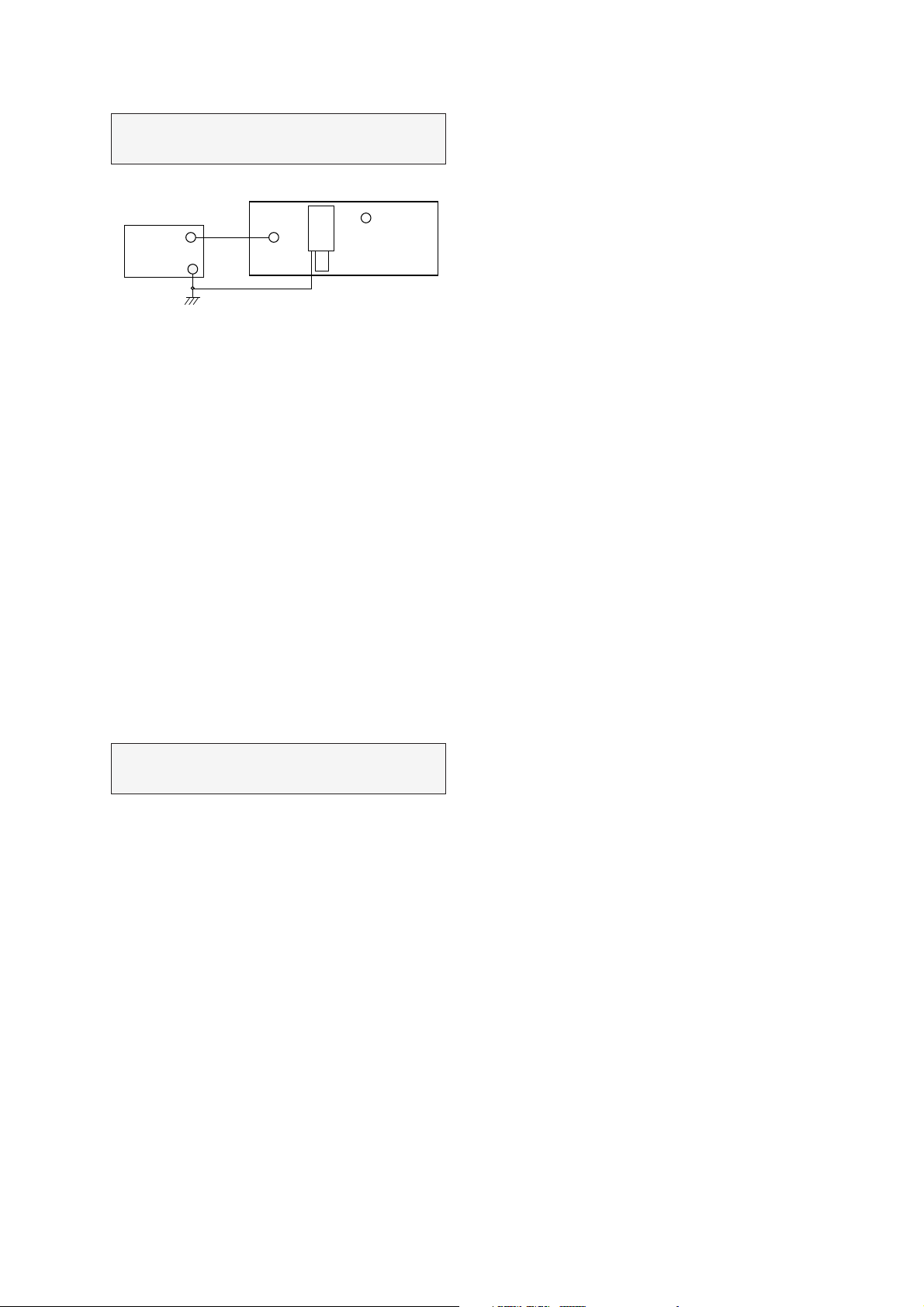
Preparation for VCO Adjustment
1. Connect the measuring equipment to the TV as shown in Fig. 1.
2. Set RF output level of sweep S.G.(Signal Generator) to 80dBuV.
3. Set Alignment Scope, Volts/Div to 100mV, AC/DC switch to
AC, Line/Ext switch to Ext.
38.9MHz
Signal
generator
GND
12Vdc
Power
Supply
GND(C26(-))
Ceramic
CAP.
10000pF
Ceramic
CAP.
10000pF
Fig.1: Connection Diagram of Equipment for BG VCO Adjustment
3
MAIN BOARD
Z101
4 5
G3962
C25(+)
C25(-)
IC101
TDA4474
J77
R124
L107
C123(+)
24
J169 5V
R139
Multimeter &
oscilloscope
2.5Vdc
SW1
AM/FM SW
GND
SW2
L/L'SW
* VCO (Voltage Controlled Oscillation) Adjustment
a) For B/G system
Test Poin t : Pin 24 of IC101 (+ lead of C123)
Adjust : L107
1) Turn on DC power supplies.
2) Adjust VCO adjust
coil(L107)so that DMM reads 2.5Vdc+_0.1V.
Page 2

Ceramic
CAP.
33.9MHz
Signal
generator
GND
12Vdc
Power
Supply
GND(C26(-))
10000pF
Ceramic
CAP.
10000pF
Fig. 2 : Connecting Diagram of Equipments for secam-L' system.
b) For Secam-L' system
3
MAIN BOARD
Z102
4 5
G3953
C25(+)
C25(-)
IC101
TDA4474
J77
R124
VR102
C123(+)
24
J139 GND
R169
Multimeter &
oscilloscope
2.5Vdc
GND(C122(-))
SW1
AM/FM SW
5V
SW2
L/L'SW
Test Poin t : J5 (one lead of R533)
Adjus t : VR102
1) Turn on DC power supplies.
2) Apply 5Vdc to the + lead of C25.
3) Adjust VCO adjust
volume(VR102) so that the DMM reads 2.5Vdc+_0.1V.
* Screen voltage adjustment
1) Tune the TV set to receive digital pattern.
2) Press PSM button on the Remote Controller to get the STANDARD picture.
3) Turn the screen VR of FBT until the black level of picutre signal is 150Vdc at the digital pattern.
CPT BOARD
GND
Rk
BLACK Level
150Vdc 1.5V
OSCILLSCOPE
Fig. 3 Fig. 4
Page 3
* RF AGC (Auto Gain Control) Adjustment
TUNER
Test Poin t : J173 or Observing Display
Adjus t : VR101
MAIN BOARD
AGC TP.
6Vdc
Digital
Multimeter
The RF AGC contro l(VR101)was aligned at the time of manufacture for optimum performance over a wide range
conditions. Readjust of VR101 should not be necessary unless unusual local conditions exist, such as ;
1) Channel interference in a CATV system
2) Picture bending and/or color beats, which are unusually due to excessive RF signal input when the receiver is too close
to a transmitting tower or when the receiver is connected to an antenna distribution system where the RF signal has
been amplified.
In this case, the input signal should be attenuated (with pad or filter) to a satisfactory level.
3) Picture noise caused by “broadcast noise” or weak signal.
If the broadcast is “clean” and the RF signal is at least 1mV (60dBu), the picture will be noise free in any area.
J173
Fig. 5
VR101
(AGC ADJ.)
Adjusting th e
Adjusting to the other end of rotation will usually cause a degradation of over load capabilities resulting in color beats or
adjacent channel reference.
For best results,
(RF level: 60dBuV).
VR101 (RF AGC)control to one end of rotation will usually cause a relatively poor signal to noise ratio;
adjust VR101 control while performing on all other local channels, or the voltage at J173 will be 6.0+_0.1Vdc.
* Focus Adjustment
NOTE : This adjustment should be performed after warming up for 10 minutes.
Test Poin t : Observing Display
Adjus t : Focus control of FBT
1) Set color & brightness to minimum, contrast to 50% respectively.
2) Input the PAL BG Digital Pattern signal.
3) Adjust the Focus control for best overall focus.
Page 4

PURITY & CONVERGENCE ADJUSTMENT
Caution:
Convergence and Purity have been factory aligned. Do not
attempt to tamper with these alignments.
However, the effects of adjacent receiver components, or
replacement of picture tube or deflection yoke may require the
need to readjust purity any convergence.
DEFLECTION YOKE
PURITY &CONVERGENCE
MAGNET ASSEMBLY
6-POLE
,,,
RUBBER
WEDGES
,,
,,
,,,
PURITY MAGNET
4-POLE
GLASS CLOTH TAPE
X-AXIS YOKE
POSITIONING
(L/R PURITY)
5.Reconnect the internal degaussing coil.
6. Position the beam bender locking rings at the 9 o'clock
position and the other three pairs of tabs (2,4 and 6 pole
magnets) at the 12 o'clock position.
6-POLE
6-POLE
MAGNETS
4-POLE
MAGNET
MAGNES
CONVERGENCE MAGNET ASSEMBLY
CONVERGENCE MAGNET ASSEMBLY
PURITY MAGNET(2-POLE)
* Purity Adjustment
This procedure DOES NOT apply to bonded yoke and picture
tube assemblies.
The instrument should be at room temperature (60 degrees F or
above) for six (6) hours and be operating at low beam current
(dark background) for approximately 20 to 30 minutes before
performing purity adjustments.
CAUTION:Do not remove any trim magnets that may be
attached to the bell of the picture tube.
1. Remove the AC power and disconnect the internal
degaussing coil.
2. Remove the yoke from the neck of the picture tube.
3. If the yoke has the tape version beam bender, remove it and
replace it with a adjustable type beam bender (follow the
instructions provided with the new beam bender)
4. Replace the yoke on the picture tube neck, temporarily
remove the three (3) rubber wedges from the bell of the
picture tube and then slide the yoke completely forward.
7. Perform the following steps, in the order given, to prepare the
receiver for the purity adjustment procedure.
a. Face the receiver in the "magnetic north" direction.
b. Externally degauss the receiver screen with the television
power turned off.
c. Turn the television on for approximately 10 seconds to
perform internal degaussing and then turn the TV off.
d. Unplug the internal degaussing coil. This allows the
thermistor to cool down while you are performing the purity
adjustment. DO NOT MOVE THE RECEIVER FROM ITS
"MAGNETIC NORTH" POSITION.
e. Turn the receiver on and obtain a red raster by increasing
the red bias control (CW) and decreasing the bias controls
for the remaining two colors (CCW).
f. Attach two round magnets on the picture tube screen at 3
o'clock and 9 o'clock positions, approximately one (1) inch
from the edge of the mask (use double-sided tape).
3-2
Page 5

1.ADJUST YOKE Z-AXIS FIRST
TO GET EQUAL BLUE
COLOR CIRCLES
MAGNETS
RED RED
2 .ADJUST BEAM BENDER 2 POLE
MAGNET TO GET FOUR EQUAL
COLOR CIRCLES
8. Referring to above, perform the following two steps:
a. Adjust the yoke Z-axis to obtain equal blue circles.
b. Adjust the appropriate beam bender tabs to obtain correct
purity (four equal circles).
9. After correct purity is set, tighten the yoke clamp screw and
remove the two screen magnets.
10.Remove the AC power and rotate the receiver 180 degrees
(facing "magnetic south").
11. Reconnect the internal degaussing coil.
12. Turn the receiver on for 10 seconds (make sure the receiver
came on) to perform internal degaussing, and then turn the
receiver off.
13. Unplug the internal degaussing coil.
14. Turn on the receiver and check the purity by holding one (1)
round magnet at the 3 o'clock and a second round magnet at
9 o'clock position. If purity is not satisfactory, repeat steps 8
through 14.
15. Turn off the receiver and reconnect the internal degaussing
coil.
* Convergence Adjustment
Caution:This procedure DOES NOT apply to bonded yoke and
picture tube assemblies.
Do not use screen magnets during this adjustment
procedure. Use of screen magnets will cause an
incorrect display.
1. Remove AC power and disconnect the internal degaussing
coil.
2. Apply AC Power and set the brightness to the Picture Reset
condition. Set the Color control to minimum.
3. Apply 8V to the pin.
6. Reconnect the internal degaussing coil and apply AC power.
7. Turn the receiver on for 10 seconds to perform internal
degaussing and then turn the receiver off again.
8. Unplug the internal degaussing-coil.
9. Turn on the receiver, connect a signal generator to the VHF
antenna terminal and apply a crosshatch signal.
Caution:During the convergence adjustment procedure, be
very careful not to disturb the purity adjustment tabs
are accidentally move, purity should be confirmed
before proceeding with the convergence adjustments.
Note:
Make sure the focus is set correctly on this instrument
before proceeding with the following adjustment.
10. Converge the red and blue vertical lines to the green vertical
line at the center of the screen by performing the following
steps (below TABLE).
a. Carefully rotate both tabs of the 4-pole ring magnet
simultaneously in opposite directions from the 12 o'clock
position to converge the red and blue vertical lines.
b. Carefully rotate both tabs of the 6-pole ring magnet
simultaneously in opposite directions form the 12 o'clock
position to converge the red and blue (now purple)
vertical lines with the green vertical line.
11. Converge the red and blue horizontal with the green line at
the center of the screen by performing the following steps.
(below TABLE)
a. Carefully rotate both tabs of the 4-pole ring magnet
simultaneously in the same direction (keep the spacing
between the two tabs the same) to converge the red and
blue horizontal lines.
b. Carefully rotate both tabs of the 6-pole ring magnet
simultaneously in same direction (keep the spacing
between the two tabs the same) to converge the red and
blue (now purple) horizontal lines with the green
horizontal line.
c. Secure the tabs previsouly adjusted by locking them in
place with the locking tabs on the beam bender.
4. Adjust the Red, Green and Blue Bias controls to get a dim
white line.
5. Remove the AC power and 8V from the pin.
3-3
Page 6

3-4
RING
PAIRS
4
POLE
ROTATION DIRECTION
OF BOTH TABS
OPPOSITE
SAME
OPPOSITE
SAME
MOVEMENT OF RED
AND BLUE BEAMS
B B
RR
OR
OR
B R B R
OR
B
R
B
R
B R
OR
B
R
6
POLE
12. While watching the 6 o'clock positions on the screen, rock the
front of the yoke in a vertical (up/down) direction to converge
the red and blue vertical lines. (Fig upper left)
13. Temporarily place a rubber wedge at the 12 o'clock position
to hold the vertical position or the yoke.
14.
Check the 3 o'clock and 9 o'clock areas to confirm that the red
and blue horizontal lines are converged.
If the lines are not converged, slightly offset the vertical tilt of the
yoke (move the rubber wedge if necessary) to equally balance the
convergence error of the horizontal lines at 3 o'clock and 9 o'clock
and the vertical lines at 6 o'clock and 12 o'clock.
15. Place a 1.5 inch piece of glass tape over the rubber foot at
the rear of the 12 o'clock wedge.
16. While watching the 6 o'clock and 12 o'clock areas of the
screen, rock the front of the yoke in the horizontal (left to
right) motion to converge the red and blue horizontal lines.
(Fig. upper right)
17. Temporarily place a rubber wedge at the 5 o'clock and 7
o'clock positions to hold the horizontal position of the yoke.
18. Check the 3 o'clock and 9 o'clock areas to confirm that the
red and blue vertical lines are converged. If the lines are not
converged, slightly offset the horizontal tilt of the yoke (move
the temporary rubber wedges if necessary) to equally
balance the convergence error of the horizontal lines at 6
o'clock and 12 o'clock and the vertical lines at 3 o'clock and 9
o'clock.
19. Using a round magnet confirm purity at the center, right and
left sides and corners. See Purity Adjustment Procedure.
20. Reconfirm convergence and apply a 1.5 inch piece of glass
tape over the rubber foot at the rear of the 5 o'clock and the 7
o'clock wedges.
RED
BLUE
RED BLUE
BLUE
RED
GREEN
GREEN
BLUE RED
GREEN
GREEN
ADJUSTMENT
VIEWING
AREA
UP/DOWN ROCKING OF THE YOKE
CAUSES OPPOSITE ROTATION OF RED
AND BLUE RASTERS
ADJUSTMENT
VIEWING
AREA
RED
RED
GREEN
TV
SCREEN
LEET/RIGHT ROCKING OF THE YOKE
CAUSES OPPOSITE SIZE CHANGE OF
THE RED AND BLUE RASTERS
UP/DOWN ROCKING OF THE YOKE
CAUSES OPPOSITE ROTATION OF RED
AND BLUE RASTERS
LEFT/RIGHT ROCKING OF THE YOKE
CAUSES OPPOSITE SIZE CHANGE OF THE
RED AND BLUE RASTERS
Page 7

TUNER
TUKE9CO7DF
VIF
TDA4474A
AUDIO SW.
LA7222
1H DELAY
TDA4665
MEGA TEXT
SDA5273/SDA5275
u-PROCESSOR
SDA30C163-2
EEPROM
24C16
EEPROM 128K
27C010A
1M DRAM
GM71C4256B
VIDEO SW.
TEA6415
50Hz C DECODER
TDA9141
DIGITAL
BOARD
(DOUBLE
SCAN)
POWER &
DEFLECTION
COLOR SW.
GD4052B
H/P AMP
TDA2882
SOUND PROCESSOR
MSP3410P
LPF
GL4558
L/S AMP
LA4282
IIC1
IIC1
AGC
CVBS
IF2
SW
2
2
2
Headphone
SPEAKER1(L)
SPEAKER2(R)
2
2
2
2
2
2
2
2
2
2
4
RGB/FB
CVBS
RESET
IIC0
IIC1 Addr & Data
Addr & Data
Co
L
R
Y
C
L
R
V
Lo/Ro2
Li/Ri2
Vo2
Vi2/Yi
Ci
Lo/Ro1
Li/Ri1
Vi1
Vo1
RGB/FB
4 RGB/FB
IIC1
IIC1
H/V
YUV50
YUV100
RGB
CPT
A66EAK552X54
RGB
IIC0 IIC1
AUDIO OUT SCART I
SCART II HALF & Y,C
FULL With
RGB
SVHS FRONT AV
100Hz VIDEO PROCESSOR
TDA 4780
VIDEO AMP & SVM
TDA6111Q X3
Page 8

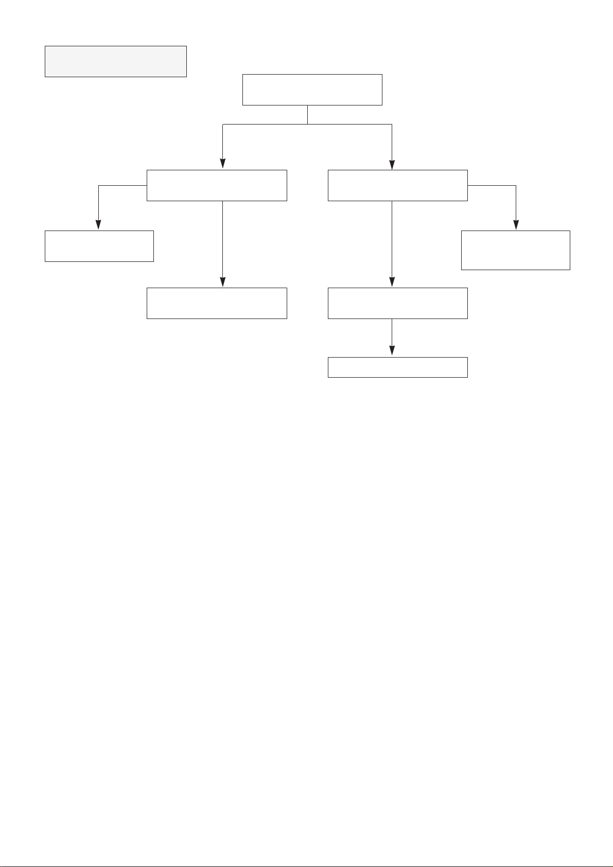
NO TELETEXT
NO RASTER
(SOUND OK)
Check the voltage
of ZD701 (5V)
Abnormal Normal
NG
NG
NG NG
Check the 5V line
to be correct.
Check if the video signal is
at pin 10 of IC702.
Check the
CVBS line.
Check/Replace
IC702, 703, X701.
Check I2C BUS lines.
(SDA, SCL)
Check pin 51, 52, 53 and 54
of IC702.
Check the voltage of
CPT Heater
Check the voltage of
HV and SCREEN of CPT.
Check/Replace
CPT Board.
Check the Heater pulse
at pin 9 of T701.
Check/Replace
T701.
Check/Replace
T701.
Check/Replace
Connector, FR459 and FR901.
Check/Replace IC503.
Page 9

NO PICTURE/NO COLOR
Is the CVBS signal at pin 14
of IC101 normal?
Check/Replace
IC101.
Is the CVBS signal at pin 26
of IC501 normal?
Check/Replace
Q201.
Is the R-Y, B-Y signal at pin 3, 4
of IC501 normal?
Check/Replace
IC501, 502.
Is the Y, U, V(in, 50Hz) signal at
pin 12, 13 and 14 of IC501 normal?
Check/Replace
IC101.
Is the Y, U, V(out, 100Hz) signal at
pin 3, 4 and 6 of P101 normal?
GO to
DIGITAL BLOCK.
Is the R, G, B signal at
pin 1, 3 and 5 of IC501 normal?
Check/Replace
IC503.
Check/Replace
IC503.
NG
NG
NG
NG
NG
NG
Page 10

NO SOUND
(PICTURE OK)
(NO AM Sound)
Check the Audio signal
at pin27 of IC101.
Check/Replace
IC101
Check the Audio signal
at pin55 of IC601.
(NO FM/NICAM Sound)
Check if the SIF signal at pin26 of
IC101 normal.
Check/Replace
IC101.
Are the Audio signal at pin28 and
29 IC601 normal?
Are the Audio signal at pin 2 and
5 of IC605 normal?
Are the Audio signal at pin 7 and
11 of IC605 normal?
Check/Replace
Connectors and Speakers.
Check/Replace
X601, IC601 and IC606.
Check LO, RO lines.
Check/Replace
IC605, Sound +B Line.
Check AM line
NG
NG
NG
NG
NG
NG
Page 11
NO PICTURE/NO SOUND
(RASTER OK)
Is the Auto programme
operation normal?
Is the CVBS signal at pin14
of IC101 normal?
yes
yes
OK
OK
no
no
no
Go to NO PICTURE Block.
NO SOUND Block
Check the voltages
5V, 12V and 33V of Tuner.
Check/Replace
ZD101, 102,
5V, 12V and 33V Lines.
Check/Replace
IC101.
Check I2C bus lines.
(SDA, SCL)
Check/Replace TUNER.
Page 12

NO RASTER
NO SOUND
Check +B voltage at J306.
Is there the square waveform at
pin4 of P101 (H-out)
140V
yes
yes
yes
OK
230~380V
Lower than 6V
no
NG
0V
no
Is the waveform at the collector of
Q402 normal?
Check/Replace
T701 and CONNECTORS.
Is the voltage at pin 24
of IC01 5V?
Check/Replace IC803,
D826, 827, 828, 829, T805,
T801, 804 and Fuse (FC02).
Check the part of
Digital PCB ASSY
Check the voltage of C834.
Check the voltage at pin9
of IC801.
Check/Replace
D802, D803, Q801 and
IC801.
Check/Replace
D801.
no
Check/Replace
Q401, T401and Q402.
Check/Replace
IC802, IC804, D810 and R832.
Page 13

Digital assy Trouble shooting
Check with Color Bar signal input.
Check the circuit from PQ101
to CQ54,57
Replace an IC causing Power
drop.
Check ICQ501.
Replace ICQ05
Replace ICQ04
Replace ICQ09
Replace ICQ08
Replace ICQ07
Replace ICQ02
Check Deflection Part
Replace ICQ01
Replace IC501
Replace ICQ06
Check IC503
No Picture or
screen flows
Check Y,U,V signal
input of PQ101.
Check Y,U,V
signals at CQ54(+),CQ57(+)
and CQ58(+).
Check the Vcc
of each IC.
Check Pin 34~40 and
Pin 48~51 of ICQ05.
Check Pin10 of ICQ06
Check Pin15 and
16 of ICQ06 for 27MHz and
13.5MHz waveform.
Check the Video
Sync at CQ54(+).
Check if Pin13 and 20
of ICQ01 have 32
¥s?
Check Pin61~68 and
Pin2~5 of ICQ04
Check Pin13~16, Pin18~21,
Pin22~25 of ICQ02.
Check the outputs
of Pin 2,4,5 of PQ102.
no
no
no
no
no good
no good
Pin13~16 no signal
Pin18~21
no signal
Pin22~25
no signal
no signal
Yes
No Picture
Screen flows
good
no good
no good
no good
good
Yes
good
Yes
good
good
Yes
Yes
Yes
Page 14

Page 15

 Loading...