

Page 1

ON/OFF
STOP PLAY
OPEN/
CLOSE
STOP/
EJECT
PLAY
REC/ITR
DVD TRK COPY VCR
REC
PM
TV
Triple Combi TV
SERVICE MANUAL
CAUTION
BEFORE SERVICING THE CHASSIS,
READ THE SAFETY PRECAUTIONS IN THIS MANUAL.
CHASSIS : MV-033A
MODEL : Multiplex 72
website:http://biz.LGservice.com
e-mail:http://www.LGEservice.com/techsup.html
SERVICE MANUAL MODEL : Multiplex 72
LG Electronics inc.
Page 2

CHASSIS : MV-033A
MODEL : Multiplex 72
CONTENT
SAFETY INSTRUCTIONS ............................ 1-2
SERVICING PRECAUTIONS ....................... 1-4
SPECIFICATION ................................................1-5
DESCRIPTION OF CONTROLS .................. 1-8
SECTION 1 SUMMARY
ON/OFF
STOP PLAY
OPEN/
CLOSE
STOP/
EJECT
PLAY
REC/ITR
DVD TRK COPY VCR
REC
PM
TV
Triple Combi TV
SERVICE MANUAL
Page 3
1-8
DESCRIPTION OF CONTROLS
TVCR DVDRESET EJECT
PSM
SSM
TV/AV
MENU
MUTE
OK
PR
VOL VOL
PR
TEXT
1 2 3
4 5 6
7 8 9 0
C o m m u n i c a t o r
SP/LP
CLR/RST
TIMER PROG
CLK/COUNT
SYSTEMARCI/II
SLEEP
RECSTOP SKIPSKIP
PAUSEFFREW
PLAY
RETURN
TITLE
SETUP
DISC MENU
ZOOMPROGRAM
?
SUBTITLE
ANGLE 3D
AUDIO
REPEATMA-B
Q.VIEW LIST
POWER
i
1
3
4
6
5
7
8
9
10
2
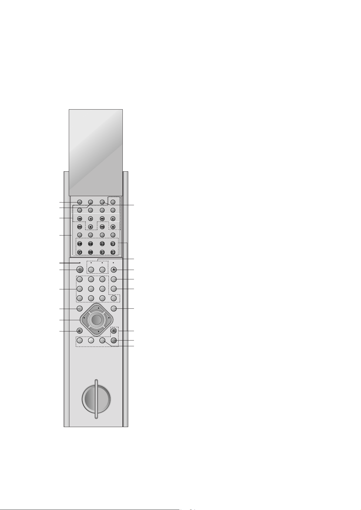
All the functions can be controlled with the Communicator.
Some functions can also be adjusted with the buttons on the front
panel of the set.
Communicator
Before you use it, please select TV, VCR or DVD function by pressing the TVCR or DVD buttons.
1. I/II
selects the language during dual language broadcast.
selects the sound output (option).
2. SLEEP
sets the sleep timer.
3. VCR BUTTONS
controls a LG video cassette recorder.
For further details, see the ‘VCR Operation’ section.
4. DVD BUTTONS
controls a LG DVD player.
For further details, see the ‘DVD Operation’ section.
5. RESET
When Communicator does not work, reset the Communicator
by pressing the reset point with sharp one.
6. POWER
switches the set on from standby or off to standby.
7. NUMBER BUTTONS
switches the set on from standby or directly select a number.
8. MENU
selects a menu.
9.
D / E
(Programme Up/Down)
selects a programme or a menu item.
switches the set on from standby.
F / G
(Volume Down/Up)
adjusts the volume.
adjusts menu settings.
OK
accepts your selection or displays the current mode.
10. MUTE
switches the sound on or off.
11. ARC (Aspect Ratio Control)
changes the picture format.
12. TVCR / DVD
selects to control a LG video cassette recorder or DVD player.
13. EJECT
Open or close the disc tray.
ejects the tape.
14. PSM (Picture Status Memory)
recalls your preferred picture setting.
15. SSM (Sound Status Memory)
recalls your preferred sound setting.
11
12
13
14
15
16
17
18
19
Page 4
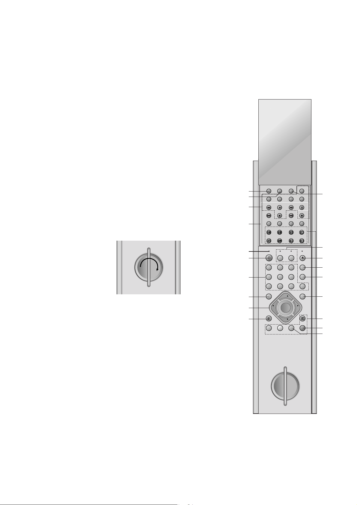
1-9
16. TV/AV
selects the remote operating mode.
clears the menu from the screen.
switches the set on from standby.
17. TELETEXT BUTTONS (option)
These buttons are used for teletext.
For further details, see the ‘Teletext’ section.
18. LIST
displays the programme table.
19. Q.VIEW
returns to the previously viewed programme.
selects a favourite programme.
COLOURED BUTTONS : These buttons are used for teletext (only
TELETEXT models) or programme edit.
Internal generator charge
The communicator can be charged with the internal electric generator. To charge the communicator do the followings;
1. In first use,
20 rotation of the handle in the arrow direction as picture below
-> waiting for one minute -> 20 rotation again -> waiting for one
minute again -> 20 rotation again -> beginning to use
2. In usual use
20 or 25 rotation -> resuming to use
Note : Do not rotate the handle too rapidly for the protection of the
communicator.
1
3
4
6
5
7
8
9
10
2
11
12
13
14
15
16
17
18
19
C o m m u n i c a t o r
CLR/RST
TITLE
ANGLE 3D
PR
OK
PR
Q.VIEW LIST
SYSTEMARCI/II
SP/LP
PAUSEFFREW
RECSTOP SKIPSKIP
RETURN
i
ZOOMPROGRAM
?
PSM
SSM
TV/AV
TEXT
SLEEP
TIMER PROG
CLK/COUNT
PLAY
SETUP
DISC MENU
SUBTITLE
AUDIO
REPEATMA-B
TVCR DVDRESET EJECT
POWER
1 2 3
4 5 6
7 8 9 0
MENU
VOL VOL
MUTE
Page 5
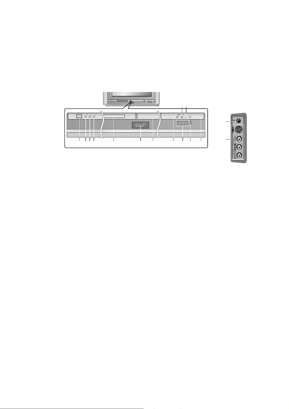
Front panel
Multiplex 72 series
Multiplex 55 series
Side panel
Shown is a simplified representation of front or side panel.
Here shown may be somewhat different from your set.
ON/OFF
STOP PLAY
OPEN/
CLOSE
STOP/
EJECT
PLAY
REC/ITR
ON/OFF
STOP PLAY
OPEN/
CLOSE
STOP/
EJECT
PLAY
REC/ITR
DVD TRK COPY VCR
REC
PM
TV
DVD TRKCOPY VCR
REC
PM
TV
AV2
13
14
1 2 3 4 5 7 8 12119
310
6
ON/OFF
STOP PLAY
OPEN/
CLOSE
STOP/
EJECT
PLAY
REC/ITR
ST-BY
REC/ITR
TIMER/REC
1-10
1. MAIN POWER (ON/OFF)
switches the set on or off.
2. STOP
Stops playback for DVD player.
3. PLAY
Starts playback for DVD player.
4. OPEN/CLOSE
Opens or closes the disc tray.
5. DISC TRAY
Places a disc on the disc tray.
6. LED (Light Emitting Diode) DISPLAY
7. CASSETTE COMPARTMENT
Inserts a video cassette tape here.
8. STOP/EJECT
stops the tape during playback or recording or
ejects the tape.
9.
DD / EE
(Programme Up/Down)
selects a programme or a menu item.
switches the set on from standby.
FF / GG
(Volume Down/Up)
adjusts the volume.
adjusts menu settings.
10. REC/ITR
starts a manual recording or instant timer
recording.
11. POWER (
rr
/ I)
switches the set on from standby or off to
standby.
12. COMMUNICATOR SENSOR
Note : Only use the supplied Communicator.
(When you use others, they’ll be not able to
function.)
13. HEADPHONE SOCKET (option)
Connect the headphone plug to this socket.
14. AUDIO/VIDEO IN SOCKETS (AV2)
Connect the audio/video out sockets of external equipment to these sockets.
S-VIDEO/AUDIO IN SOCKETS (S-Video)
(option)
Connect the video out socket of an VCR to the
S-VIDEO socket.
Connect the audio out sockets of the VCR to
the audio sockets as in AV2.
15. STANDBY / REC/ITR / TIMER REC
INDICATOR
Page 6
3-2
ADJUSTMENT INSTRUCTIONS
1. APPLICATION RANGE
These adjustment instructions is applied to MV-033A chassis.
2. Notes
2.1. Because this is a cold chassis, it is not necessary to use an
isolation transformer.
But operate it using a transformer between the power
supply line and chassis input to prevent electric shock and
to protect the test instrument.
2.2. All adjustment must be done in correct sequence.
However, for the better productivity, it can be changed in
pre-permitted range.
2.3. Environment conditions : If not specified, it must be done in
following conditions.
1) Temperature : 25
cC ! 5 cC
2) Humidity : 65 % ! 10 %
2.4. Power supply of a SET which is adjusted is AC110-240V,
50/60Hz.(EU model : AC230V,50HZ)
2.5. If not specified, the receiver must be operated for more
than 20 minutes prior to the adjustment.
2.6. Signal
Receive the standard color signal. (65dB ! 1dB uV)
LG standard signal means the digital pattern PAL-B/G
05CH.
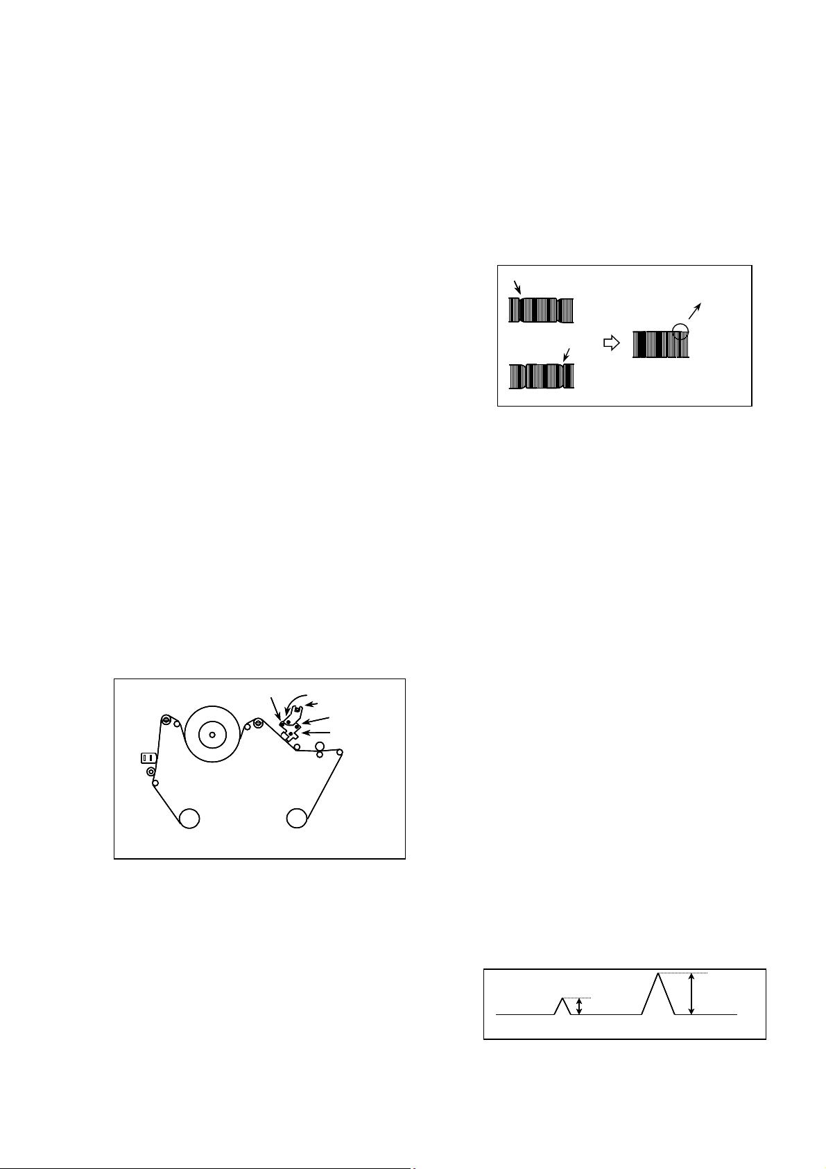
3. DECK Line Adjustment.(VCR DECK Part)
3.1. P2/P3 Pre-Adjustment
3.1.1. Necessary Instrument
1) PAL SP Normal TAPE
2) OSCILLOSCOPE
3) 10:1 PROBE : 2 PIECES
4) SPECIAL NUT DRIVER (for P2/P3 Control)
3.1.2. Adjustment
1) Play the PAL standard Tape(SP).
2) Connect to J261(H/SW) the OSCILLOSCOPE(CH-1) on
the MAIN1 PCB.
3) Connect to J219(RF) the OSCILLOSCOPE(CH-2) on the
MAIN1 PCB.
4) With observing the RF envelope waveform, adjust P2, P3
until it becomes the waveform C.
5) Check the envelope waveform is in the maximum size by
pressing the TRK UP(+).
3.2. CTL/AUDIO LEVEL ADJUSTMENT
3.2.1. NECESSARY INSTRUMENT
1. CTL TAPE
2. PAL SP Standard TAPE(for Audio level adjustment)
3. OSCILLOSCOPE
4. 10:1 PROBE : 2 PIECES
5. RMS METER(for Audio level adjustment)
3.2.2. CTL ADJUSTMENT
THIS ADJUSTMENT MUST BE DONE WHEN THE
UNCONTROLLED DECK IS WAREHOUSED.
1) Connect the OSCILLOSCOPE to J101(CTL)
2) After playing the CTL control tape, make sure the CTL
waveform range is From 1.5 :1 to 2.5 : 1.
If it is out of range , adjust CTL waveform to the following
procedures.
¤ If is over 2.5 :1, lower the head height.
After turning the height adjust screw counter-clockwise
to adjust its level from 1.5 : 1 to 2 : 1. Check the tape
location at P4. Readjust the TILT.(2:1)
¤ŁIf is under 1.5:1, heighten the head height.
After turning the height, adjust the screw clockwise to
adjust its level from 2 : 1 to 2.5 : 1. Check the tape
location of P4. Readjust the TILT.(2:1)
3) Play the standard tape and adjust the azimuth screw right
and left by using the oscilloscope and level-meter to
maximize the audio sound.
Adjust the azimuth screw & the height adjust screw at the
same time because they have mutual relationship.
(Check CTL again after the adjustment)
*A/C head adjustment order
Height adjust screw->check the TILT->azimuth screw->
check CTL
P2
<A> P2 POST ADJUSTMENT
P3
D
<B> P3 POST ADJUSTMENT
D
<C> The Waveform after adjustment
TAKE- UP
REEL
AZIMUTH ADJUST SCEW
CAPSTAN
T/UP ARM
SUPPLY
REEL
DRUM
P2
P3
FE HEAD
P1
TENTION ARM
P4
P0
TAKE- UP
REEL
AZIMUTH ADJUST SCEW
CAPSTAN
T/UP ARM
SUPPLY
REEL
DRUM
P2
P3
FE HEAD
P1
TENTION ARM
P4
P0
TAKE- UP
REEL
AZIMUTH ADJUST SCEW
CAPSTAN
T/UP ARM
SUPPLY
REEL
DRUM
P2
P3
FE HEAD
P1
TENTION ARM
P4
P0
X-Value Fixed Screw
X-Value Adjustment Hole
Tilt Adjustment screw
Height Adjustment Screw
PINCH - ROLLER
<Fig1> Adjustment Position
<Fig2> P2/ P3 Adjustment Waveform
1
2
CTL WAVEFORM
1
2
CTL WAVEFORM
1
2
CTL WAVEFORM
<Fig3>
Page 7

3-3
3.2.3 AUDIO LEVEL Checking and adjustment
1) Connect “+” terminal of RMS meter(Auto level meter) to
C392 on the main PCB Audio out and “-” terminal to
GND.
2) Check that if audio level of RMS meter satisfies with the
spec, If audio sound is weak, adjust the A/C head
azimuth screw.
3) Audio level spec
1K :0.5 ! 0.1Vrms
6K :1KHz ! 1.5dB
3.3. X-DISTANT/P2,P3 ADJUSTMENT
3.3.1. NECESSARY INSTRUMENT
1) SP PAL TAPE
2) OSCILLOSCOPE
3) 10:1 PROBE : 2 PIECES
4).SPECIAL DRIVER FOR ADJUSTMENT(P2,P3,XDISTANT(NUT),AUDIO(NUT))
5) RMS METER(AUDIO LEVEL METER)
3.3.2. ADJUSTMENT PREPARATION
1).Connect oscilloscope(CH-1) to J261(H/SW) on main PCB.
(Use for trigger of CH-2 )
2) Connect oscilloscope(CH-2) to J261(RF) on main PCB.
(Use waveform of CH-2)
3) Play by inserting SP PAL TAPE. (2HD:normal tape)
4) After the picture is appeared, make initial condition by
pressing the tracking adjustment up(+) button of the
remote controller.
3.3.3. X-DISTANCE ADJUSTMENT
1) Turn the X-distant adjust groove of the deck right and left
to maximize the scope waveform.
2) Check that if waveform satisfies with the linearity by
pressing TRK Up(+) and Down(-) button.
3) Tighten the X-distant adjust screw.
3.3.4. P2/P3(RF LINEARITY) CHECK & ADJUSTMENT
1) Adjust p2 & p3 so that the the RF envelope waveform of
the oscilloscope becomes C in figure 2.
2) Check if the envelope waveform becomes maximum by
pressing TRK Up(+),Down(-) button one step.
3.4. PG ADJUSTMENT
Adjust it after finishing controlling the Deck.
3.4.1.NECESSARY INSTRUMENT
1) SP PAL TAPE
2) OSCILLOSCOPE
3) 10 : 1 PROBE : 2 PIECES
3.4.2. ADJUSTMENT
1) Insert and play the SP PAL TAPE.
2) Connect the oscilloscope(CH-1) to H/SW(J261) on the
main PCB and trigger in setting the VOL/DIV to 1V range.
3) Connect the oscilloscope(CH-2) to video out(C571) on the
main PCB and set the VOL/DIV to 500mV range.
4) Set the TIME/DIV of oscilloscope to 50us range.
5) If press P-CHECK of SVC Remote control “A-PG>>>” is
appeared in the display, and PG adjustment signal
become 412uS ! 100uSec.
4. ASSEMBLY LINE ADJUSTMENT
4.1. DVCO adjustment
1) This is for adjustment of VCT3834, crystal oscillator
frequency after receiving a company Digital pattern.
(PAL : EU05CH, NTSC : 13CH)
2) When entering adjustment mode by pressing IN-START
button, DVCO adjustment is operating automatically. (T/X
doesn’t operating occasionally during DVCO adjustment,)
4.2. FOCUS ADJUSTMENT
1). Receive the LG standard pattern(digital pattern, Fig5).
2). Set the picture condition on ‘STANDARD’ mode.
3)Adjust the focus volume of FBT for the best focus of
horizontal line A, vertical line B.
4.3. Purity & Convergence adjustment
4.3.1. PURITY adjustment
1) Preparation
¤ Receive the RED Raster Pattern for purity adjustment.
(P-50CH or N-11CH)
¤ŁDemagnetize the CPT and Cabinet with a degaussing
coil.
2) Adjustment
¤ Pre-adjust the static convergence(STC) with 4 and 6-
pole magnet.
¤Ł Push the DY(deflection Yoke)all the way to the CPT
panel.
¤Ø Turn the purity magnet(2-pole magnet) so that the
‘green’ portion of left side and the ‘blue’ portion of right
side have same portion.
¤Œ Pull the DY slowly and fix it when the whole screen
become red.
4.3.2. Convergence adjustment
1) Preparation
¤ Receive the cross Hatch pattern for convergence
adjustment.(P-07CH or N-09CH)
¤Ł Let the contrast at the adequate luminance level.
ADJUST PERIOD (6.5H = 412us)
PG ADJUST WAVEFORM
*CAUTION: SET THE TRIGGER MODE OF OSCILLOSCOPE TO DC
ADJUST PERIOD (6.5H = 412us)
PG ADJUST WAVEFORM
*CAUTION: SET THE TRIGGER MODE OF OSCILLOSCOPE TO DC
<Fig4>
<Fig 5>
Page 8

3-4
2) Adjustment
¤ Converge the RED vertical line and BLUE vertical line
the same line by changing the angle between the 2 tab
of the 4pole magnet.
¤ŁConverge the RED horizontal line and BLUE horizontal
line in the same line by turning the table of the 4 pole
magnet. This time, go not change the angle between
the 2 tabs.
¤ØConverge the R, G, B vertical line in the same line by
changing the angle between the 2 tabs of the 6 pole
magnet.
¤Œ Converge the R, G, B horizontal line in the same line
by turning the 2 tabs of the 6 pole magnet. This time,
do not change the angle between the 2 tabs.
4.4. Screen Voltage adjustment
1) Receive the PAL or SECAM(NTSC) signal into RF mode
regardless of channel.
2) If you press the ADJ button in LINE SVC mode(IN-START
button), the LINE SVC mode changes to screen
adjustment mode.
3) Turn the Screen Volume of FBT to changes luminance of
White signal center as shown below.
4) Press the EXIT button to exit SVC mode.
4.5 White Balance adjustment
4.5.1 Necessary Instrument
1) Auto White Balance Meter
2) Color Analyzer (CA-100)
3) Factory Remote control
* Prior to this adjustment, the Screen Voltage Adjustment must
be finished.
4.5.2 Adjustment
1) Make the picture luminance 35Ft-L by changing the
“CONTRAST” and “BRIGHTNESS”.
2) Enter the white balance adjust mode with a factory remote
control.
3) Adjust HIGH Light status of WDR R, WDR B.
4) Make the picture luminance 4.5Ft-L by changing the
‘contrast’ and ‘brightness’.
5) Adjust LOW Light status of CUT R CUT B at CUT B.
6) Repeat 1) ~ 5) until both low and high light have same
color temperature.
* Note : When adjusting White balance automatically, connect
the adjustment JIG in SVC mode. (When pressing IN-START,
MUTE button on remote control for adjustment orderly, it
changes to SVC mode and screen displays SVC.)
* WHITE BALANCE INITIAL VALUE
CR,CG,CB => 80
WR,WG,WB => 800
4.6. Deflection data adjustment
4.6.1. Preparation
1) At adjustment mode (IN-START button on remote control
of adjustment), changed to LINE SVC 2 mode to adjust
the deflection.
2) Press Channel UP/DOWN button for desirous function
adjustment.
3) Press Volume UP/DOWN button to adjust the data.
4) Tune the TV set to receive a Digital pattern.(PAL :
EU05CH, NTSC:13CH)
4.6.2. Deflection setting data adjustment
* Note : First, adjust deflection at N50Hz, W50Hz, Z50Hz of
PAL signal.
Then adjust deflection at N60Hz, W60Hz, Z60Hz of
NTSC signal.
In case of NTSC only model, adjust deflection at
N60Hz, W60Hz, Z60Hz of NTSC signal
¤ When adjusting a deflection, adjust N50Hz of PAL
signal first and adjust a deflection at W50Hz,
Z50Hz,N50Hz, W60Hz, Z60Hz of PAL signal.
¤ŁAdust a deflection as shown below
PAL 4:3 -> PAL 16:9 -> PAL ZOOM -> NTSC 16:9 ->
NTSC ZOOM
¤ØAfter finishing deflection adjustment, press the ENTER
button to enter or exit in SVC mode.
1) VA (Vertical Amplitude)
Adjust so that the circle of a digital circle pattern may be
located within the effective screen of the CPT.
2) VL (Vertical Linearity)
Adjust so that the boundary line between upper and lower
half is in accord with geometric horizontal center of the
CPT
3) SC (Vertical S-Correction)
Adjust so that all distance between each horizontal lines
are to be the same.
4) VS (Vertical Shift)
Adjust so that the horizontal center line of a digital circle
pattern is in accord with geometric center of the CPT.
5) HS (Horizontal Shift)
Adjust so that the vertical center line of a digital circle
pattern is in accord with geometric vertical center of the
CPT.
6) EW (East-West Width)
Adjust so that a digital circle pattern looks like exact.
<Table 1> Convergence Spec. & Test Position
CPT & INCH
29”FLAT
21”FLAT
29”FLAT
21”FLAT
Luminance(Manual Adj.)
9 ! 1 FL
12 ! 1 FL
9 ! 1 FL
12 ! 1 FL
Luminance(Auto Adj.)
27 Cd
42 Cd
27 Cd
42 Cd
Description
KZ Model
KZ Model
KF Model
KF Model
<Table 2> Screen Voltage Adjust Spec.
X
Y
Temp.
EU
288
295
9000
Non-EU
268
273
13000
<Table 3> white Balance Adjust Spec.
Page 9

3-5
7) ET (East-West Trapezium)
Adjust to make the length of top horizontal line same with
it of the bottom horizontal line.
8) EP (East-West Parabola)
Adjust so that middle portion of the outermost left and
right vertical line looks like parallel with vertical lines of the
CPT.
9) ES (East-West Symmetric)
Adjust until the upper and lower corner of the screen
symmetric.
10) EC (East-West Corner)
After completing the EP adjustment, adjust so that the
corner vertical line to be straight.
11) BOW
Adjust the left and right crooked line on upper and lower
side.
12) ANGLE
Adjust the vertical slope.
<Table 4> Initial deflection data & conversion data for each mode
(Line SVC-2) (50Hz is initial data and the other data are
compensated conversion.)
5. SVC Dat & PSM,SSM Setting Data
Picture Setting Data (LINE SVC-3) : No need of adjustment
<Table 5>
<Table 6> Picture Mode Initial Setting Value
O Shipment Condition
In the last assembly line before packing, below setting are
should be made (Using IN-STOP KEY)
<TAble 7>
PAL NTSC
<Fig.6>
VA
VL
SC
VS
HS
EW
ET
EP
ES
EC
BOW
ANGLE
Vertical Amplitude
Vertical - Linearity
S - Correction
Vertical Shift
Horizontal Shift
East - West Width
East - West Trapezium
East - West Parabola
East - West Symmetric
East - West corner
Bow Correction(Quadratic)
Angle Correction(Linear)
0050~00CF
0025~00BF
0000~009F
0600~0900
0000~003F
0400~0EFF
0700~08FF
06E0~0840
06A0~0AFF
0790~08E0
-256~255
-256~255
00A1
00FB
00D0
0738
0017
0B04
07F8
07B0
0840
0825
0000
0000
160
0
-32
-224
39
464
20
66
0
48
0
0
OPTION CONTENTS RANGE
N50Hz
21” 29”
DVCO
BCLTH
BCLTM
BCLGN
SVG1
SVDEL
SVD1
LDLY1
DSCC
DSCV
HBSO
VBSO
Digital VCO
BCL TRERHOLD
BCL TIME
BCL GAIN
SVM GAIN
SVM DELAY
SVM DELAY1
L DELAY
Discharge Sample Count
Vertical Discharge Value
BLACK CURRENT
WHITE CURRENT
-2048~2047
0~2047
0~15
0~15
0~1FFH
0~6
0~6
0~511
0~511
00A1
00FB
00D0
0738
0017
0B04
07F8
07B0
0840
0825
0000
0000
160
0
-32
-224
39
464
20
66
0
48
0
0
OPTION CONTENTS RANGE
21”
FLAT
29”
FLAT
CONTRAST
BRIGHT
COLOR
SHARPNESS
100
60
60
50
90
50
50
40
60
60
40
30
50
60
40
30
Mode DYNAMIC STANDARD MILD GAME
No.
1
2
3
4
5
6
7
8
9
10
11
12
13
14
CONTENTS
POWER
TV / AV INPUT
MEMORY CHANNEL
SOUND
MUTE
DBS
PSM
SSM
CHILD LOCK
AUTO SLEEP
AVL
BALANCE
BLUE BACK
TILT
CONDITION
OFF
TV
Refer CH. Memory
spec. sheet
30 STEPS
OFF
OFF
DYNAMIC
FLAT
OFF
OFF
OFF
0
OFF
0
REMARK
29” Option
Page 10

3-6
6. Option Adjustment
6.1. Preparation for Adjustment
1) This decides function in accordance with model.
Press the SVC TX adjustment button (IN-START button) at
SVC model, then adjust the option at OPTION 1, 2, 3 mode.
2) Mark the option adjustment data like (90, 96, 4) in B.O.M.
O Mark of BOM
The OPTION 1 data is 90, the OPTION 2 data is 96, the
OPTION 3 data is 4 in this model.
6.2. Adjustment
6.2.1. Adjustment Method
1) Input data directly by the buttons corresponded with
OPTION 1 ??(0~255), OPTION 2 ??(0~255), OPTION 1
??(0~255).
2) Select each OPTION function by the CH/DOWN button
and then set up each OPTION by th VOL UP/DOWN
button.
6.2.2 OPTION-1 Function
6.2.3. OPTION-2 Function
6.2.4. OPTION-3 Function
option
(90, 96, 4)
option
option
LEVEL1PART NO.
3141VMNN40A
SPECIFICATION
MAIN, MV033A
DESCRIPTION
CHASSIS ASSY
JOP EXP.
(90,96,4)
OPTION
SCART
TOP
(TELETEXT)
ACMS
CH+AU
DEG
TILT
SYS
CODE
0
1
0
1
0
1
0
1
0
1
0
1
0
1
2
3
FUNCTION
PHONE JACK
SCART JACK
W/O TOP (FLOP BASIC)
WITH TOP (Only applied some
EU nation with TOP)
WITHOUT ACMS FUNCTION
WITH ACMS FUNCTION
ALL NATION
CHINA & AUSTRALIA ONLY
WITHOUT DEGAUSSING
WITH DEGAUSSING
W/O TILT(NORMAL MODEL,
EXCEPT AUSTRALIA)
WITH TILT (FLAT AUSTRALIA
NORMAL MODEL)
B/G, I DK, L/L’
B/G, I, DK
M
PAL-N/M M
REMARK
21”
Option
OPTION
TSS (Turbo
search)
DUAL
(Dual Save)
V-CUR
(Vol.)
HOTEL
M-VOL
MONO
CODE
0
1
0
1
0
1
0
1
1~100
0
1
FUNCTION
WITHOUT TURBO SEARCH
WITH TURBO SEARCH
NO SAVE DUAL/SOUND CONDITION
SAVE DUAL/SOUND CONDITION
NORMAL VOLUME
CURVE
WITHOUT HOTEL OPTION
WITH HOTEL OPTION
MAX
FORCED MONO NO SETTING
FORCED MONO SETTING
REMARK
EU
NON EU
NON EU
with HOTEL
OPTION
OSD
LANG
TXT
LANG
CODE
0
1
0
1
0
1
2
3
4
5
0
1
2
3
4
5
FUNCTION
ENGLISH Only
ENGLISH, GERMANY, FRENCH,
ITALIAN,SPANISH, RUSSIAN
ENGLISH Only
ENGLISH, FRENCH, ARABIC, URDU
WEST EU (Eng / Fre / Swedish / Czech /
German / Spanish / Italian)
EAST EU (Polish/ Fre/ Swedish/ Czech/
Slovenian/ Ita/ Rumanian)
TURKEY (Eng/ Fre/ Swedish/ Turkish/
German/ Spanish/ Italian)
CYILLIC3 (Eng/ Russian/ Estonian/ Czech/
Ger/ Ukrainian/ Lettish)
GREEK3(Eng/ Fre/ Swedish/ Turkish/ Ger/
Spanish/ Italian/ Greek)
RESERVED
WEST EU (Eng/ Fre/ Swedish/ Czech/
German/ Spanish/ italian)
EAST EU (Polish/ Fre/ Swedish/ Czech/
Slovakian/ Italian/ Rumania)
TURKEY (Eng/ Fre/ Swedish/ Turkish/
German/ Spanish/ Italian)
CYILLIC3 (Eng/ Russian/ Estonian/ Czech/
German/ Ukrainian/ Lettish)
ARAB/ ENGLISH (Eng/ Fre/ Turkish/ Arab)
RESERVED
REMARK
EU
VERSION
ARAB
VERSION
EU
VERSION
ARAB
VERSION
Page 11

3-7
BLOCK DIAGRAM
Page 12

3-8
Page 13

3-9
Page 14

TROUBLE SHOOTING
NO Play Of VCR, DVD
Check the voltage
of P03 pin2,4 12V &13.5V
Check The VCR
SMPS Board
0V
YES
OK
Error Lamp Flicker ?
Check / Replace
Deck Assy
NO
Check/ Replac e
Mode Switch P02
No Play Of VCR
Open/ Close Control ?
Check /Replace The
DVD Loader
NG
OK
No Play Of DVD
Check the voltage of P751A
pin1.3.6 3.3V.12V.5.3V?
Bad Disc ,No Disc
On the Menu
Check the Disc
Condition
Check the Regional
Code On Disc
Check The VCR
SMPS Board
NO
OK
3-10
Page 15

3-11
NO Raster : No Monitor on
Check AC Power
at P801
Is the voltage at D824
(B+)?
Check
RL701(Relay)
Check the power
CTL of IC01 Pin27
Check Waveform
of P821 Pin9(H-out)
Check Q401
collector waveform
Check T402
& voltage
Check &replace
IC501
Check &replace
Q401
Check the in/ out
of IC801
Check the
D801
Check /replace
RL701
OK NO
OK
OK
Yes
No
No
No
No
OK
Open
Go to No Power
Block
No
Page 16

3-12
NO Sound / Picture OK
Select correct
system in MENU
Check the waveform
of PIN 4,12 IC851
Check the waveform
of PIN 27,28 IC601
Check the Freq of
X600(X-tal )
CheckVcc/ replace
IC851
OK
NO
NO
OK
Check / replace
P500(Connector)
OK
Check / replace
Tuner Audio Line
OK
Check / replace
VCC, IIC line
NO
Page 17

3-13
NO Picture / SOUND OK
Check the Waveform of
IC501 Pin42,43,44
Check
FR901,FR401
Check
FBT T402
Check the
Heater Volt 6.0V~ 6.4V?
Check The Main
Power Board
OK
OK Not OK
Check/ Replac e
IC501
Not OK
Check VCC of IC501
Pin 3.15.25,45,54
3.3V or 5V?
OK Not OK
Page 18

3-14
NO Play Of VCR, DVD
Check the voltage
of P03 pin2,4 12V &13.5V
Check The VCR
SMPS Board
0V
YES
OK
Error Lamp Flicker ?
Check / Replace
Deck Assy
NO
Check/ Replac e
Mode Switch P02
No Play Of VCR
Open/ Close Control ?
Check /Replace The
DVD Loader
NG
OK
No Play Of DVD
Check the voltage of P751A
pin1.3.6 3.3V.12V.5.3V?
Bad Disc ,No Disc
On the Menu
Check the Disc
Condition
Check the Regional
Code On Disc
Check The VCR
SMPS Board
NO
OK
Page 19

P/NO: 3854VA0122A - S1(1/2)
2004.2.26
Page 20

P/NO: 3854VA0122A - S1(2/2)
2004.2.26
 Loading...