

LG LW9424-B Owner’s Manual
MODELS
LW9424 Megapixel Network PTZ Camera
Safety Information
2
This Class A digital apparatus complies with Canadian
ICES-003.
Cet appareil numérique de la classe A est conforme à
la norme NMB-003 du Canada.
SSaaffeettyy IInnffoorrmmaattiioonn
This lightning flash with
arrowhead symbol within an
equilateral triangle is intended to
alert the user to the presence of
uninsulated dangerous voltage
within the product’s enclosure
that may be of sufficient
magnitude to constitute a risk of
electric shock to persons.
The exclamation point within an
equilateral triangle is intended to
alert the user to the presence of
important operating and
maintenance (servicing)
instructions in the literature
accompanying the product.
FCC WARNING: This equipment may generate or use
radio frequency energy. Changes or modifications to
this equipment may cause harmful interference unless
the modifications are expressly approved in the
instruction manual. The user could lose the authority
to operate this equipment if an unauthorized change
or modification is made.
REGULATORY INFORMATION: FCC Part 15
This equipment has been tested and found to comply
with the limits for a Class A digital device, pursuant to
Part 15 of the FCC Rules. These limits are designed to
provide reasonable protection against harmful
interference when the equipment is operated in a
commercial environment. This equipment generates,
uses, and can radiate radio frequency energy and, if
not installed and used in accordance with the
instruction manual, may cause harmful interference to
radio communications. Operation of this equipment in
a residential area is likely to cause harmful
interference in which case the user will be required to
correct the interference at his own expense.
A suitable conduit entries, knock-outs or glands
shall be provided in the cable entries of this
product in the end user.
Caution: Danger of explosion if battery is
incorrectly replaced. Replaced only with the same
or equivalent
type recommended by the manufacturer. Dispose
of used batteries according to the manufacturer’s
instructions.
Holes in metal, through which insulated wires
pass, shall have smooth well rounded surfaces or
shall be provided with brushings.
3
To disconnect power from mains, pull out the mains
cord plug. When installing the product, ensure that
the plug is easily accessible.
Warning: Do not install this equipment in a confined
space such as a bookcase or similar unit.
Warning: Wiring methods shall be in accordance with
the National Electric Code, ANSI/NFPA 70.
Warning: This is a class A product. In a domestic
environment this product may cause radio interference
in which case the user may be required to take
adequate measures.
Warning: To reduce a risk of fire or electric shock, do
not expose this product to rain or moisture.
Caution: This installation should be made by a qu
alified service person and should conform to all local
codes.
Caution: To avoid electrical shock, do not open the
cabinet. Refer servicing to qualified personnel only.
Caution: The apparatus should not be exposed to
water (dripping or splashing) and no objects filled
with liquids, such as vases, should be placed on the
apparatus.
Caution: This product employs a Laser System. To
ensure proper use of this product, please read this
owner’s manual carefully and retain it for future
reference. Should the unit require maintenance,
contact an authorized service center. Performing
controls, adjustments, or carrying out procedures
other than those specified herein may result
inhazardous radiation exposure. To prevent direct
exposure to laser beam, do not try to open the
enclosure. Visible laser radiation when open. DO NOT
STARE INTO BEAM.
Safety Information
LG Electronics hereby declares that
this/these product(s) is/are in
compliance with the essential
requirements and other relevant
provisions of Directive 2004/108/EC,
2006/95/EC, and 2009/125/EC.
European representative :
LG Electronics Service Europe B.V.
Veluwezoom 15, 1327
AE Almere. The Netherlands
(Tel : +31-(0)36-547-8888)
Disposal of your old appliance
1. When this crossed-out wheeled bin
symbol is attached to a product it means
the product is covered by the European
Directive 2002/96/EC.
2. All electrical and electronic products
should be disposed of separately from
the municipal waste stream via
designated collection facilities appointed
by the government or the local
authorities.
3. The correct disposal of your old
appliance will help prevent potential
negative consequences for the
environment and human health.
4. For more detailed information about
disposal of your old appliance, please
contact your city office, waste disposal
service or the shop where you purchased
the product.
EEE Compliance with Directive. (for Turkey only)

Safety Information
4
IMPORTANT SAFETY
INSTRUCTIONS
1. Read these instructions.
2. Keep these instructions.
3. Heed all warnings.
4. Follow all instructions.
5. Do not use this apparatus near water.
6. Clean only with dry cloth.
7. Do not block any ventilation openings. Install
in accordance with the manufacturer’s
instructions.
8. Do not install near any heat sources such as
radiators, heat registers, stoves, or other
apparatus (including amplifiers) that produce
heat.
9. Do not defeat the safety purpose of the
polarized or grounding-type plug. A polarized
plug has two blades with one wider than the
other. A grounding type plug has two blades
and a third grounding prong. The wide blade
or the third prong are provided for your
safety. If the provided plug does not fit into
your outlet, consult an electrician for
replacement of the obsolete outlet.
10. Protect the power cord from being walked on
or pinched particularly at plugs, convenience
receptacles, and the point where they exit
from the apparatus.
11. Only use attachments/accessories specified
by the manufacturer.
12. Use only with the cart, stand, tripod, bracket,
or table specified by the manufacturer, or
sold with the apparatus. When a cart is used,
use caution when moving the cart/apparatus
combination to avoid injury from tip-over.
such as power-supply cord or plug is
damaged, liquid has been spilled or objects
have fallen into the apparatus, the apparatus
has been exposed to rain or moisture, does
not operate normally, or has been dropped.
Safety Precautions
Do not attempt to disassemble the camera
To prevent electric shock, do not remove screws
or covers. There are no user serviceable parts
inside. Ask a qualified service personnel for
servicing.
Avoid the camera with direct sunlight
Do not aim the camera at bright objects. Whether
the camera is in use or not, never face it with
direct sunlight or other extremely bright objects.
Otherwise blooming or smear may be caused.
Handle the camera with care
Do not abuse the camera. Avoid striking, shaking,
etc. The camera could be damaged by improper
handling or storage.
Do not use strong solvents or detergents
Use a dry cloth to the camera when it is dirty. If it
is hard to remove the dirt on the camera, use a
mild detergent and wipe it gently.
Do not install this camera upside down
This camera is designed for mounting on the
ceiling or wall. If you install this camera upside
down, for example, mounted on the floor, it may
cause malfunction.
Do not use the camera in such places as shown
below. The lens may become cloudy due to
condensation if the camera is used under the
following conditions.
Rapid temperature fluctuation by switching an air
conditioner on and off.
13. Unplug this apparatus during lightning
storms or when unused for long periods of
time.
14. Refer all servicing to qualified service
personnel. Servicing is required when the
apparatus has been damaged in any way,
Rapid temperature fluctuation due to frequent
door opening and closing.
Use in an environment where eyeglasses become
foggy.
Use in a room filled with cigarette smoke or dust.
If the lens becomes cloudy due to condensation,
remove the dome cover and wipe all moist
surfaces
with a soft cloth.
Before operating, please check proper

5
temperature, humidity and power source ratings.
Use the camera under conditions where
temperature is from -10 °C to 50 °C and humidity
is below 80 %. The input power source is AC 24 V.
Consumables
Parts having contacts such as the lens-drive
motors, cooling fan built inside the camera are
subject to wear with time. About replacement and
maintenance of such parts, please ask the nearest
service center.
Camera Installation Location
Discuss the installation location for the camera with
your retailer, and select a place that is strong enough
for the installation.
Install the camera on a ceiling (concrete, etc.) at a
location that is sufficiently strong to support it.
Safety Information
Doing so may cause internal components to damage
more easily or malfunction.
Do not wire cables near power lines.
Tightening the Screws
Screws should be tightened sufficiently in accordance
with the materials and structure of the installation
location. After tightening the screws, visually inspect
them to make sure there is no unevenness and that
each screw is tight.
Install the camera body on the foundation section
of the building or sections having sufficient
bearing strength.
Never install or use the camera in the following
locations
Do not install it in areas exposed to direct
sunlight or rain.
Do not install the camera near the air outlet of an
air conditioner.
Near a swimming pool or other areas where
chemicals are used.
Food preparation areas and other locations where
there are large amounts of steam vapor and oil, in
flammable atmospheres, other special
environments.
Areas where radiation, X-rays, strong electric
waves, or magnetism is generated.
At sea, in coastal areas, or in areas where
corrosive gas is being generated.
Areas outside of the allowable ambient operating
temperature range.
About Static Electricity Removal
Before installing the camera, touch a metal case or
other metallic parts with your hand to remove static
electricity from your body.
Do not install in areas subjected to high amounts of
humidity or dust.

Safety Information
6
Contents
Safety Information .............................................................. 2
IMPORTANT SAFETY INSTRUCTIONS................. 4
Safety Precautions ...................................................... 4
Preparation ............................................................................. 7
Introduction ................................................................... 7
Feature ............................................................................. 7
Accessories .................................................................... 8
Optional Accessories ................................................. 8
Part Names and Functions ..................................... 9
Installation ............................................................................ 10
Connection .................................................................. 10
Basic Connection Overview ......................... 10
ALARM input connection .............................. 11
ALARM output connection .......................... 11
Connecting power source ............................ 11
Connecting Network ....................................... 11
Connecting IP Reset Cable ........................... 11
Connecting Audio ............................................ 11
Camera ID Setting ............................................ 11
Protocol and baud rate settings ................ 12
Mounting the camera ............................................. 13
Wall mount (optional) .................................... 13
System Operation ............................................................. 14
Remote Video Monitoring .................................... 14
Initialization of IP address..................................... 15
Remote Configuration..................................................... 16
Using Web Brower ................................................... 16
System Configuration ............................................. 17
Video Configuration ................................................ 19
Audio Configuration ................................................ 22
Network Configuration .......................................... 23
Serial Configuration ................................................. 26
Event Configuration ................................................. 28
PTZ Configuration .................................................... 31
Record Configuration .............................................. 34
User Configuration ................................................... 38
Camera Configuration ............................................ 39
Open source software notice....................................... 42
Appendix ............................................................................... 43
Specifications .............................................................. 43
Dimension .................................................................... 45

7
PPrreeppaarraattiioonn
Introduction
This User Manual provides information on operating
and managing the megapixel IP PTZ camera. The
Manual includes instructions of installation, operation
and configuration of megapixel IP PTZ camera as well
as how to make troubleshooting.
Feature
This product is a megapixel PTZ network-based
camera with remote live monitoring, audio monitoring
and control via an IP network such as LAN,
ADSL/VDSL, and Wireless LAN.
Camera
1/3” 2 MegaPixel CMOS
x20 optical zoom, x12 digital zoom
True Day & Night (ICR)
Video
Highly efficient compression algorithm, H.264 &
MJPEG support
Resolutions: CIF (352x240) – HD (1920x1080)
Wide range of transmission rates: 256kbps ~ 10Mbps
Motion detection
Composite video output
Audio
Multi-transmission mode: Simplex (megapixel IP PTZ
camera Client PC, Client PC megapixel IP PTZ
camera), Full Duplex
Network
Fixed IP & Dynamic IP (DHCP) support
1:1, 1:N support
Multicasting
Various types of Protocol support : TCP/IP, UDP,
Multicast, DHCP, SMTP, HTTP, SNMP, RTP, RTSP
Serial Data
RS-485 support
Sensor and Alarm
Support direct connections of external sensor and
alarm devices
Event Alarm notification.
Preparation
2 alarm sensor Inputs and 2 alarm Output relays are
available
If an external sensor is activated, camera can be set to
move to the corresponding Preset position.
User Interface
Live monitoring and system configuration through LG
Smart station and LG Smart Web Viewer.
High Reliability
Reliable embedded system
System Recovery using dual watchdog
Powerful Pan/Tilt Functions
Max. 360/sec high speed Pan/Tilt Motion
Using Vector Drive Technology, Pan/Tilt motions are
accomplished in a shortest path. As a result, time to
target view is reduced dramatically and the video on
the monitor is very natural to watch.
For jog operation using a controller, since ultra slow
speed 0.05/sec can be reached, it is very easy to
locate camera to desired target view. Additionally it is
easy to move camera to a desired position with
zoom-proportional pan/tilt movement.
Preset, Pattern, Swing, Group
MAX. 128 Presets are assignable and characteristics of
each preset can be set up independently,
Max. 8 set of Swing action can be stored. This enables
to move camera repetitively between two preset
positions with designated speed.
Max. 4 of Patterns can be recorded and dplayed back.
This enables to move camera to follow any trajectory
operated by joystick as closely as possible.
Max. 8 set of Group action can be stored. This enables
to move camera repetitively with combination of
Preset or Pattern or Swing. A Group is composed of
max. 20 entities of Preset/Pattern/Swings.
PTZ(Pan/Tilt/Zoom) Control
With RS-485 communication, max. 255 of cameras can
be controlled at the same time.
Pelco-D or Pelco-P or LG multix protocol can be
selected as a control protocol in the current version of
firmware..
Easy Installation and Perfect Outdoor Environment
Compatibility
Fans and heaters are built-in in camera for cold and
hot temperature environment. Also idealistic
Preparation
8
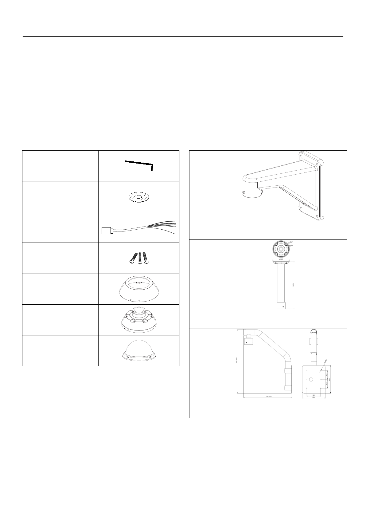
Wrench Driver
Installation CD
Alarm I/O Connector
Screw (SAMS M3X10)
Cover Adaptor
Mount Adaptor
Dome Cover Ass’y
Wall
Mount
Bracket
[Screws : Machine M1450,
Hex Lag #1450]
Pole
Mount
Bracket
[Screws : Machine M1450,
Hex Lag #1450]
Para
Mount
Bracket
[Screws : Machine M1450,
Hex Lag #1450]
mechanical design protects camera from water and
dust. (IP 66)
It is easy to install and maintain camera with terminal
for cable connection in brackets.
Accessories
Optional Accessories
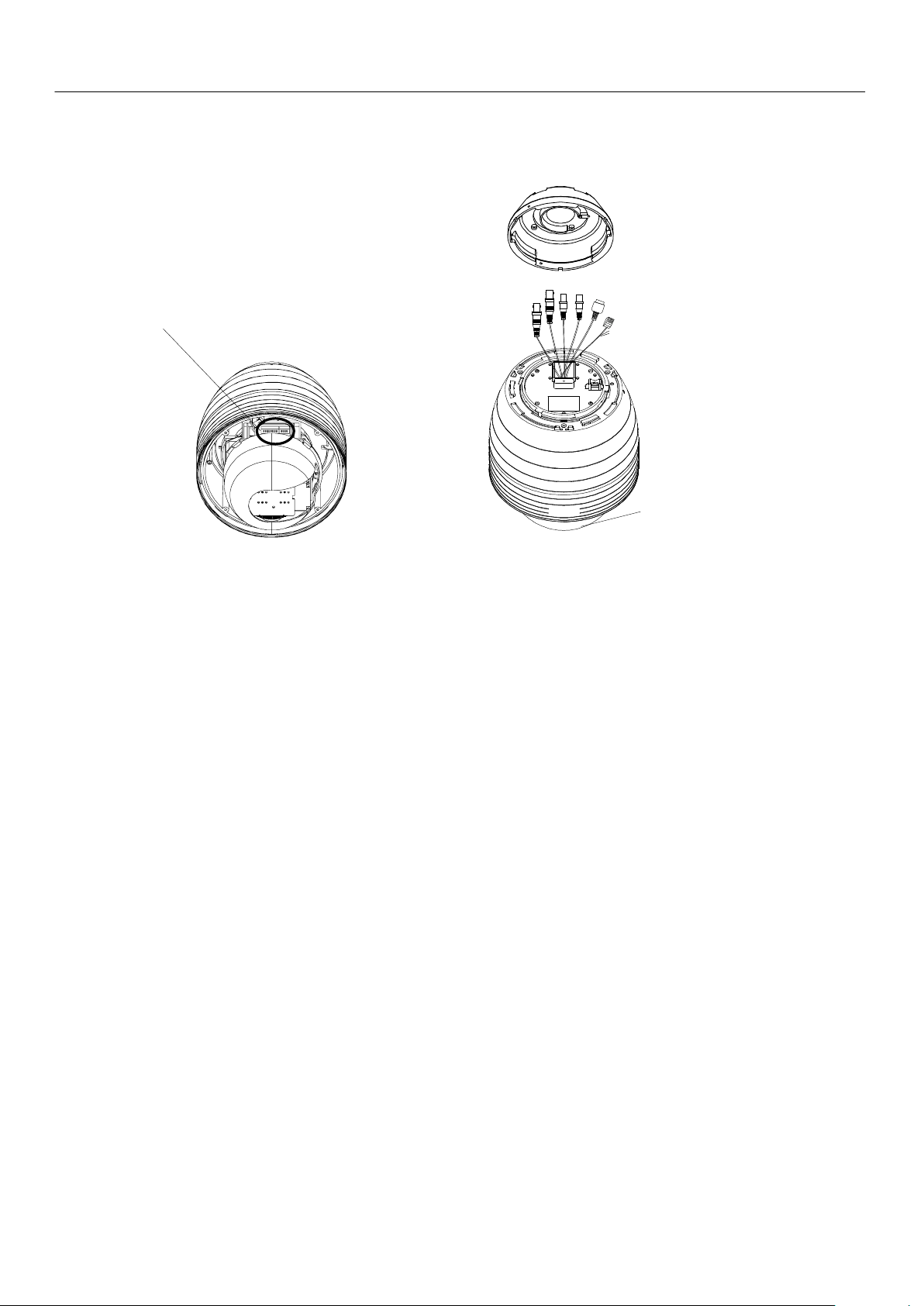
9
DIP Switch
Dome Cover
Power Connector
Video Out Connector
Audio In Connector
Audio Out Connector
LAN Connector
Alarm I/O Adaptor
Dome Cover
Do not detach protection vinyl from dome cover before
finishing all installation process to protect dome cover
from scratches or dust.
DIP Switch
Sets up camera ID and protocol.
Drop Prevention Spring
This part keeps the camera from dropping during
installation and maintenance. After install the Bracket,
please, hang the spring to the drop prevention hook of
main body as shown in picture for further tasks.
Mounting Screw Hole
This hole is for screws that assembles the main body with
a bracket.
Alarm I/O Connector
The RS-485 communication cable, alarm in/out connection
cable and IP Reset cable. (See table “Port Description of
Alarm I/O Pin out”)
Video (BNC)
Used for the composite video out connection.
LAN Port
Used for the Ethernet connection
Audio Port
Used for the audio in/out connection.
Part Names and Functions
Installation
10
Sit e
R em ote Center
(P C SW )
R e m ot e Ce n t e r
S ite
Bitrate
NO. of Clients
Bitrate
NO. of Clients
10Mbps
1
3Mbps
4
7Mbps
2
2Mbps
5
5Mbps
3
1Mbps
7
Site
R e m ote Center
Browser
Power
MIC Sp eaker
INTERNE T
Controller / DVR
RS-485
LAN Cable
Audio
Cable
DC12V
IR
Sensor
Door
Switch
Sensor I/O
Monitor / DVR
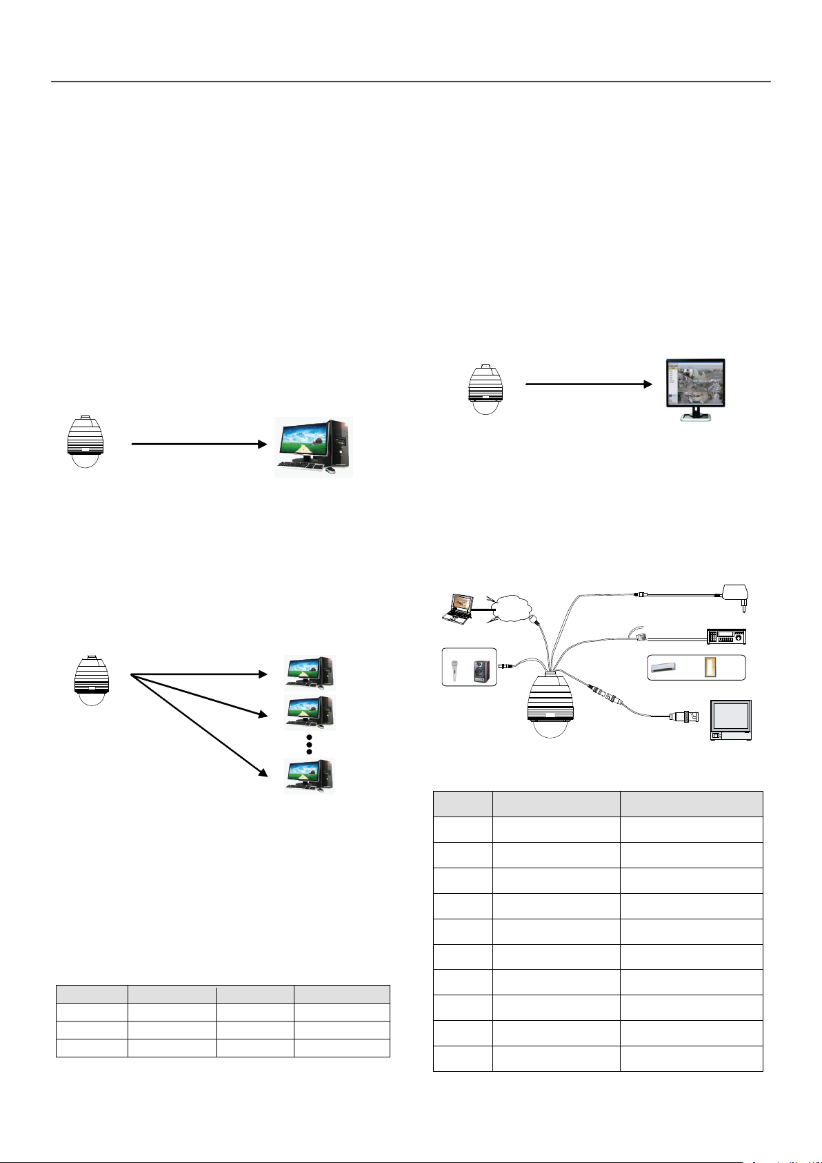
BNC
Color
Signal
Description
GRAY
ALARM IN <COM>
GROUND
WHITE
ALARM IN 1
GREEN
ALARM IN 2
ORANGE
ALARM OUT <COM>
Relay Common
PINK
ALARM OUT 2
Normal Open Relay Out
BLUE
ALARM OUT 1
Normal Open Relay Out
RED
RS 485 +
B:ACL
RS 485 -
VIOLET
IP RESET
IP Address Reset
BROWN
GND
GROUND
IInnssttaallllaattiioonn
Megapixel IP Camera can be connected in either 1 to
1 connection where one camera is connected to one
PC client or 1 to many connections where one camera
can be connected to several PCs.
Connection
Topology
Generally, LW9424 megapixel Network PTZ Camera
and PC is connected in 1-to-1 mode or 1-to many
configuration.
1:1 Connection .
One camera is installed at a site where video images
are transmitted. A PC is installed at a central location
to receive and view the video images on an analog
monitor. Audio and serial data are transferred in either
direction.
1:N Connection .
Multicast Mode
If the network supports multicasting, a large number
of PCs can be used to receive video effectively from a
camera using a single streaming of video and audio.
However, multicast mode is possible only when
network environment supports multicast.
Smart Station
Smart station is a Window-based remote monitoring
program in order to monitor or control video, audio,
and events in real time from several IP cameras. Please
refer to the Smart station User Manual for more in
detail.
Basic Connection Overview
In this configuration, a site can be monitored from
many remote central locations. Although up to 64 PCs
can be connected to one camera, in the real network
environment, network bandwidth can limit the
maximum connections.
In case that a PTZ is connected to more than 1 client,
to get stable images, the number of client is limited
for each Bitrate as below.
Port Description of Alarm I/O Pin out
Installation
11
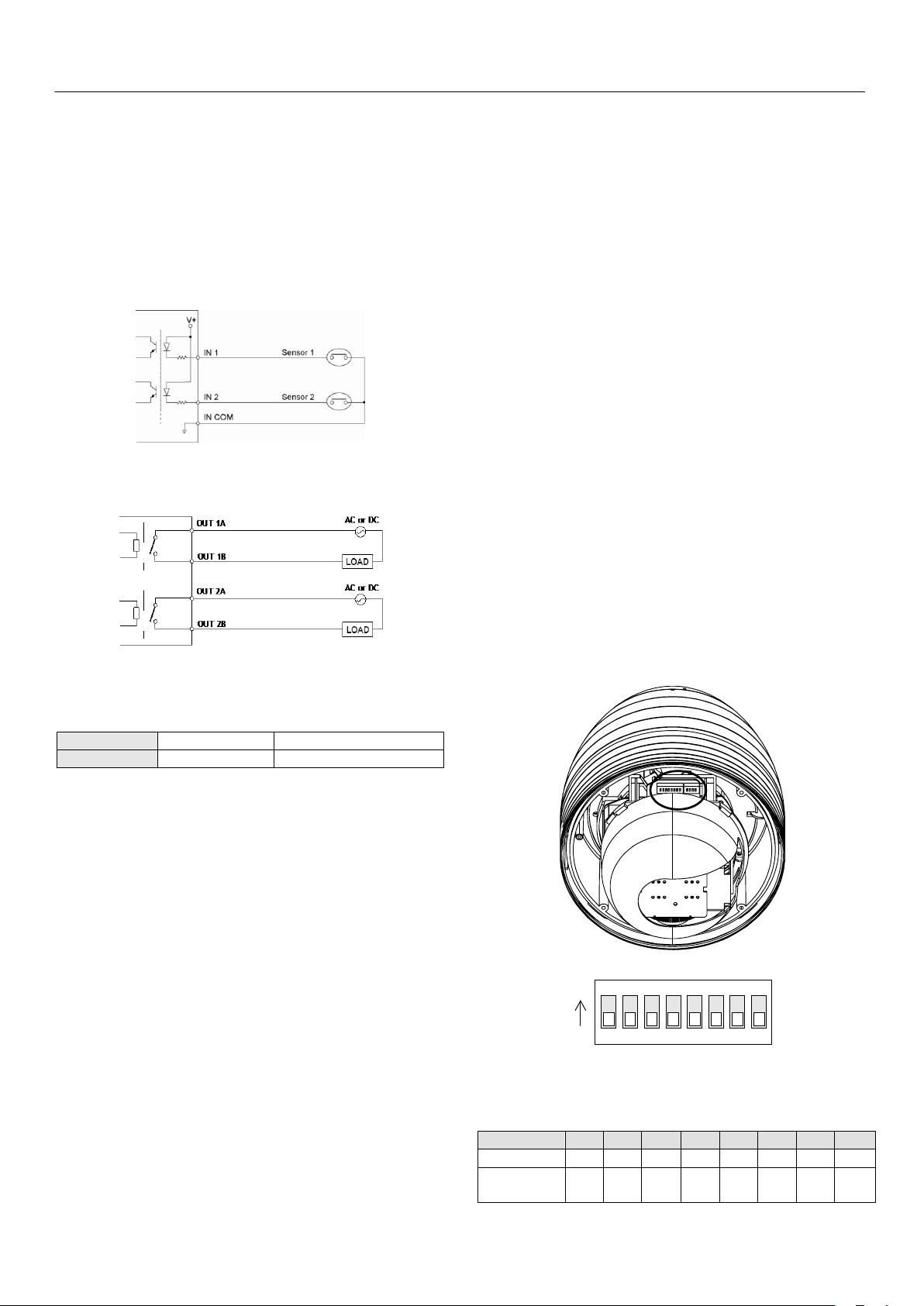
Drive Power
DC Power
AC Power
Max. Load
Max DC 24V, 1A
Max AC 125V, 0.5A
ON
ON
1 2 3 4 5 6 7 8
Pin 1 2 3 4 5 6 7 8
ID Value
1 2 4 8 16
32
64
128
ex) ID=5
on
off
On
off
off
off
off
off
ex) ID=10
off
on
Off
on
off
off
off
off
ALARM input connection
Before connecting wires to sensors, check operation
voltage and output type of sensors. there are 2 output
types in sensor output, Open Collector and Voltage
Output, properly connect wires to sensors according
to sensor output type.
Sensor Input
ALARM output connection
Relay Output
Maximum allowable electrical load of relay is shown
bellow table.
Connecting Network
Plug network cable to Ethernet port (RJ-45 network
port).
Connecting IP Reset Cable
Reset its network configuration to the factory defaults.
IP address obtain from DHCP server. To initialize the
Network setting to the factory default, press the reset
button for more than 5 seconds
Connecting Audio
Audio is full-duplex. It is possible to set the mode as
Tx-only, Rx-only or Tx-Rx.
Connect AUDIO IN and AUDIO OUT ports to audio
devices accordingly.
The Audio signal required is line level, so audio
equipment with an amp, mixer or other amplifier
should be used.
Camera ID Setting
When you control the camera through RS-485, before
installation, you should set the DIP switches to
configure the camera ID, communication protocol.
Connecting power source
Carefully check the voltage and current capacity of the
rated power. The rated power is indicated in the back
of main unit.
After confirming the power source, connect power
adaptor and connect the 12V DC connector to the
system
For the DC input models, be careful with the polarity
of DC power. The system should be permanently
damaged by wrong DC input.
In case that the length of the power wire is very long,
there may be voltage drop and the system may not
work properly. Make the length of the power wire as
short as possible.
This camera must always be operated by AC 24 V or
DC 12 V Certified/Listed,Class 2 power supply only.
ID numbers of camera are set up with binary
numbers..
See the examples shown below
Installation
12
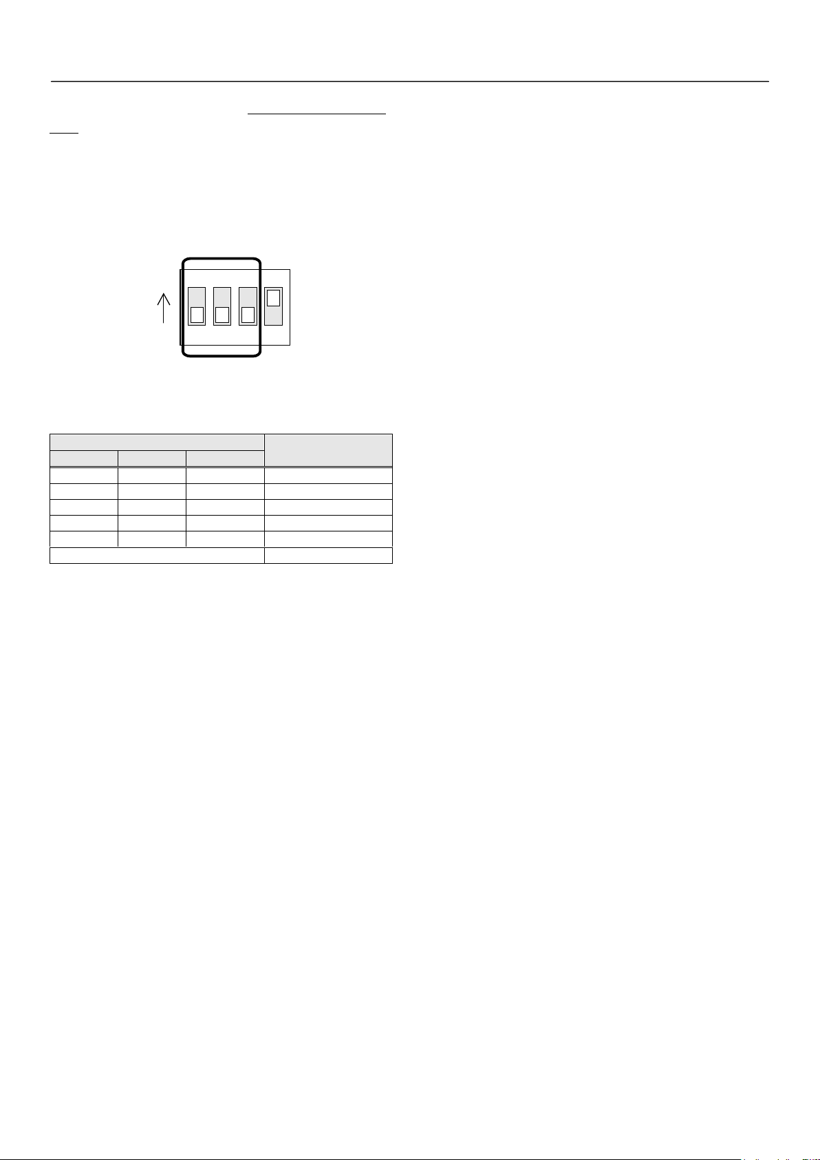
1 2 3 4
ON
ON
Switch State
Protocol/Baud rate
P0 (Pin 1)
P1 (Pin 2)
P2 (Pin 3)
OFF
OFF
OFF
PELCO-D, 2400 bps
ON
OFF
OFF
PELCO-D, 9600 bps
OFF
ON
OFF
PELCO-P, 4800 bps
ON
ON
OFF
PELCO-P, 9600 bps
OFF
OFF
ON
LG Multix, 9600bps
Otherwise
Reserved
The camera ID range is 1~255. Camera ID must not
be 0.
Factory default of Camera ID is 1.
Match the camera ID with Cam ID setting of your DVR
or Controller to control the camera.
Protocol and baud rate settings
Select the appropriate Protocol with DIP switch
combination.
If you want to control using DVR or P/T controller,
their protocol must
be identical to camera. Otherwise, you can not control
the camera.
Adjust the DIP switch after turning off the camera. If
you changed the camera protocol by changing the
DIP switch, the change will be effective after you
reboot the camera.
Factory default of protocol is “LG Multix, 9600 bps”.
13
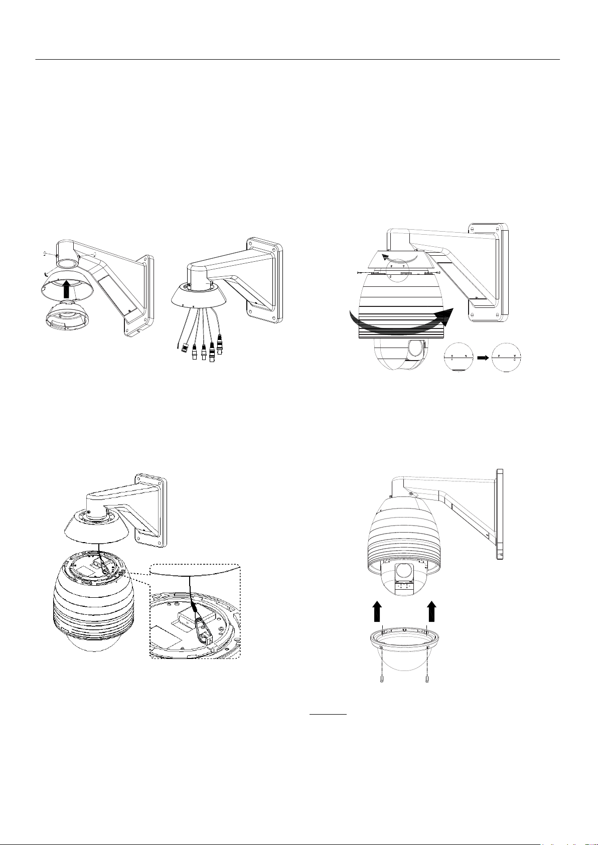
Mounting the camera
Wall mount (optional)
① Place the cover adaptor between the wall mount
bracket and the mount adaptor. Then assemble the
mount adaptor with the wall mount adaptor with 3
screws(M5 x 15).
Installation
③ Align the arrow stud of the main body with the
arrow stud of the cover adaptor and slightly push the
main body to the mount adaptor. Then turn the main
body clockwise and assemble the main body with the
mount adaptor with 3 screws(SAMS M3x10). And align
the arrow stud of the cover adaptor with the arrow
stud of the main body and turn the cover adaptor
counterclockwise.
② Hook up “Drop Prevention Spring” on main body
to prevent camera from unexpected drop and pull the
wire(s) and cable(s) for the system as below.
④ Remove the sticker and Zoom module cap. Screw
the dome cover to the main body and remove the
protection vinyl from the dome cover.
Notice
Before starting the installation, make sure that the
Camera ID and Protocol are set up properly.
System Operation
14
Default ID: admin / PW: admin
SSyysstteemm OOppeerraattiioonn
Remote Video Monitoring
There are two ways to monitor video when the center
system and LW9424 are connected. In order for a
proper operation, an IP address must be set
accordingly. Please refer to Remote Setting for further
details.
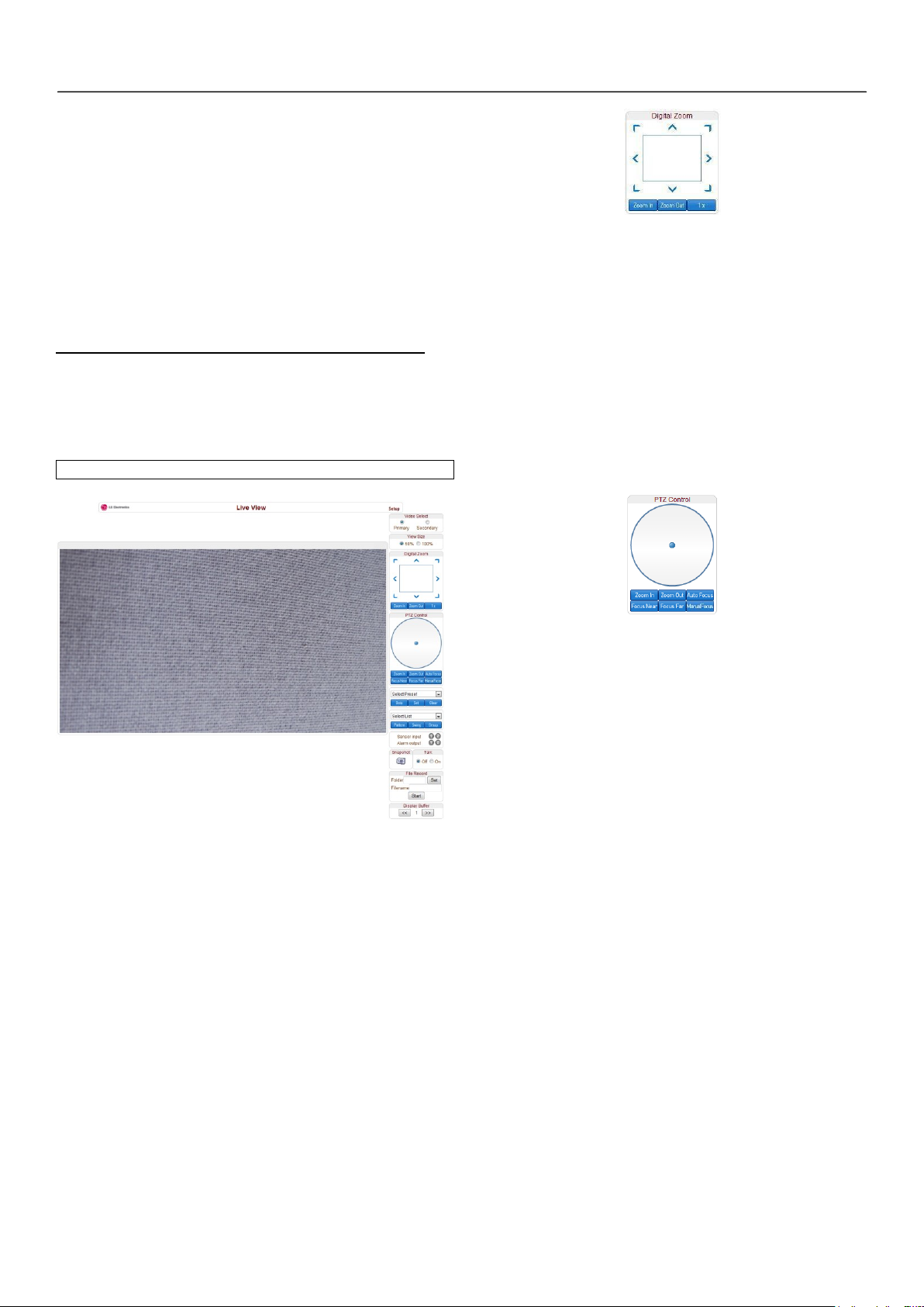
Video Monitoring using Internet Explorer
Open Internet Explorer and enter camera’s IP address.
The system will ask for confirmation to install Active-X
control. Once authorized, the Internet Explorer will
start to display video images from camera as shown.
Control the Digital zoom on the screen
The more the camera zooms in, the smaller the square
of control panel is. Position of the image can be
changed by moving position of the square. Max x5
Digital Zoom is available.
If you press x1, the screen will return to the normal
size. This digital zoom function is operated on a web
browser and different from digital zoom function of a
camera.
PTZ Control Panel (Optical Zoom & Digital zoom
built-in the camera)
Video Selection
Select the Video stream to be viewed: Primary or
Secondary
This camera is capable of dual streaming; primary
streaming and secondary streaming.
Video will be displayed according to the resolution set
on video configuration. If dual streaming (“Use Dual
Encode” Menu in Video page) is not activated,
secondary video is not available
Screen Size
Adjust the Screen size
Screen size is initially adjusted according to the
compression resolution. If you click 50% icon, the
whole screen size will be reduced to half size.
Digital Zoom
Control PTZ and PTZ Control Panel is used for
controlling external PTZ devices when the external PTZ
devices are connected through serial port.
It is possible to make zooming control by Zoom
in/out buttons of PTZ control Panel (In order to use
digital zoom, select Digital zoom ON in the Camera
tab)
Focus Near, Focus Far, Auto Focus, Manual Focus
Adjust the focus of the lens
Select Preset
Set preset position and move to the specific preset
position.
- Goto: Move to the selected preset entry if the preset
entry is set.
- Set: Set the current position to the selected preset
entry.
- Clear: Delete the selected preset entry.
Select List
Run a selected Pattern or Swing or Group.
After selecting an entry in the list, Pattern, Swing or
Group button can be pressed. Then, corresponding
operation is executed for the selected list.
(Please refer to the PTZ tab to set Pattern, Swing and
 Loading...