

Page 1

INSTALLATION MANUAL
LED TV*
* LG LED TV applies LCD screen with LED backlights.
Please read this manual carefully before operating your set and
retain it for future reference.
LU660H-S*
Copyright © 2018 LG Electronics Inc. All Rights Reserved.
www.lg.com
Page 2

TABLE OF CONTENTS
ENGLISH
ENG
3 LOCATION AND FUNCTION OF
CONTROLS
3 Parts and Button
3 - Basic functions
3 - Adjusting the Menu
4 EZMANAGER
4 Introduction
4 Ez-Manager Wizard
5 - Automatically for Setup
9 - Manually for Setup
12 - USB LG Smart Install Utility
13 INSTALLATION MENU
13 Introduction
14 PUBLIC DISPLAY SETTINGS
14 Public Display Settings Operation
15 Power On Status
15 Volume (0 ≤ Min ≤ Start ≤ Max ≤ 100)
15 - Start Volume
15 - Maximum Volume
15 - Minimum Volume
16 Key Management
16 - IR Operation
16 - Local Key Operation
16 Limited Mode
16 - Setup Menu
16 - Channel Change
17 - Menu Display
17 - OSD Display
17 - System Provider Mode
17 DTV Channel Update
18 Power On Default
18 - Input
18 - Channel
18 - A/V Setting
18 - Aspect Ratio
18 Aux Source Setting
18 Power Management
18 Factory Reset
19 NETWORK
19 MAC Address
19 Network Setting
20 LG Connect
20 IP Stream Control
20 Wake On LAN
21 PRO:CENTRIC
21 Mode
21 Update Event
22 Media Type
22 Room Number Setting
23 GENERAL
23 Configuration Setup
24 External Speaker
24 Set ID Setup
25 Power Saving
25 HCEC Setup
26 Clock Setup
26 Password Change
27 Preloaded App
27 Lock Mode
27 MEDIA SHARE
27 SmartShare
27 Screen Share
28 Media Renderer
28 DIAL
28 TV Name
28 SoftAP
29 TV MANAGER
29 USB Download Menu
35 Diagnostics
36 KEY CODES
37 EXTERNAL CONTROL DEVICE
SETUP
37 RS-232C Setup
37 USB to Serial converter with USB Cable
37 RS-232C with RS-232C Cable
38 Set ID
39 Communication Parameters
39 Command reference list
40 TRANSMISSION / RECEIVING
PROTOCOL
2
Page 3
LOCATION AND FUNCTION OF CONTROLS
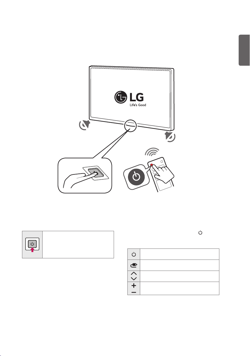
Parts and Button
ENGLISH
Basic functions
Power On (Press)
Power Off 1 (Press and Hold)
Menu control (Press 2)
Menu selection (Press and Hold 3)
1 All running apps will close.
2 You can access and adjust the menu by
pressing the button when TV is on.
3 You can use the function when you access
menu control.
Adjusting the Menu
When the TV is turned on, press the button
one time. You can adjust the Menu items
using the button.
Turns the power off.
Changes the input source.
Scrolls through the saved channels.
Adjusts the volume level.
3
Page 4

EZMANAGER
ENGLISH
ENG
* Image shown may differ from your TV.
Introduction
The Pro:Centric Platform enables you to simply install, manage and use guest-centric solutions. The
default Domain ‘procentric.local’ and IP Server Address are needed to be registered in DNS TV will
contact the IP Server using the default Domain ‘procentric.local’ via IP on server search page. If TV
doesn’t contact the Server, TV will search the pre-defined channel earlier than all channels.
Ez-Manager Wizard
• If you are using Pro:Centric, this setup wizard till help you easily set up the TV. Select NEXT to
continue.
• Otherwise, if you will not be installing a Pro:Centric Server, select X to quit.
4
Page 5
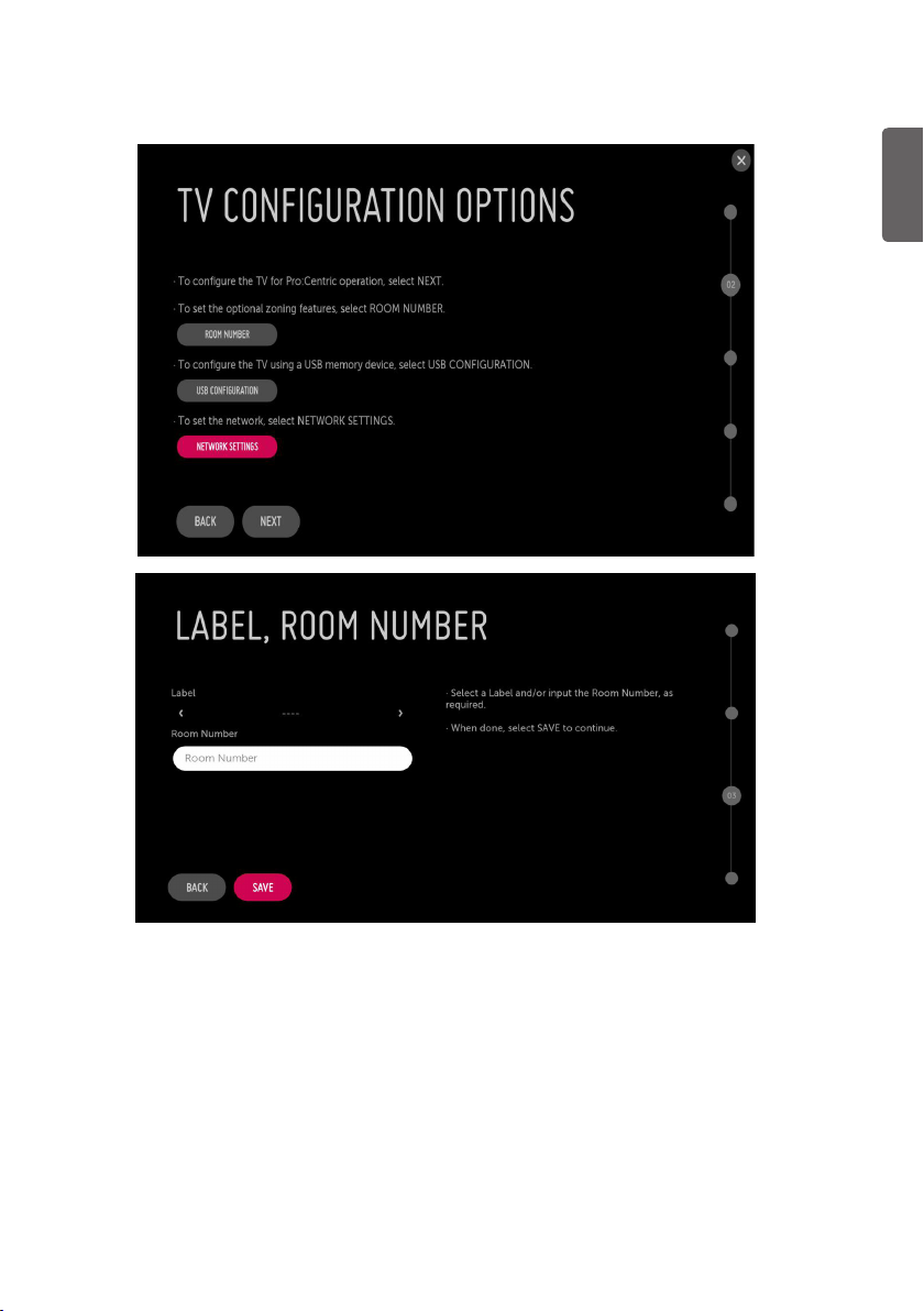
Automatically for Setup
ENGLISH
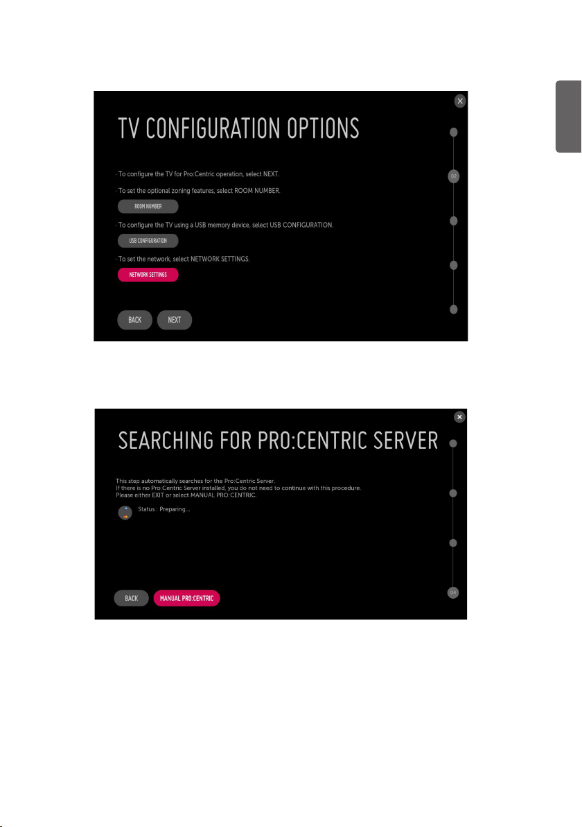
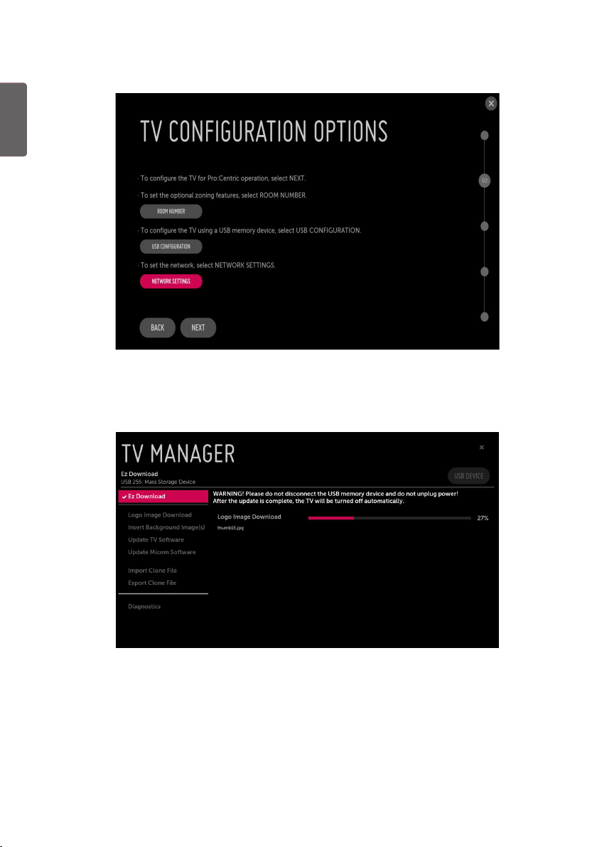
1 From the TV Configuration Options screen, you can choose how to proceed with the
configuration of this TV. Whether you will configure the TV for Pro:Centric operation via the
wizard or use a USB memory device to configure the TV, you may first wish to set the Room
Number on the TV.
• If you intend to set Room Number as part of the TV configuration, use the Room Number
option to assign the Room # for this TV before you continue with additional configuration.
• In the Label field, use the Left/Right arrow keys to specify a North, South, East, or West
designation for this TV.
• In the Room Number field, you can use the number keys on the Installer Remote to direct enter
a room number or use the virtual keyboard on the TV screen.
• To continue, move and select NEXT.
5
Page 6
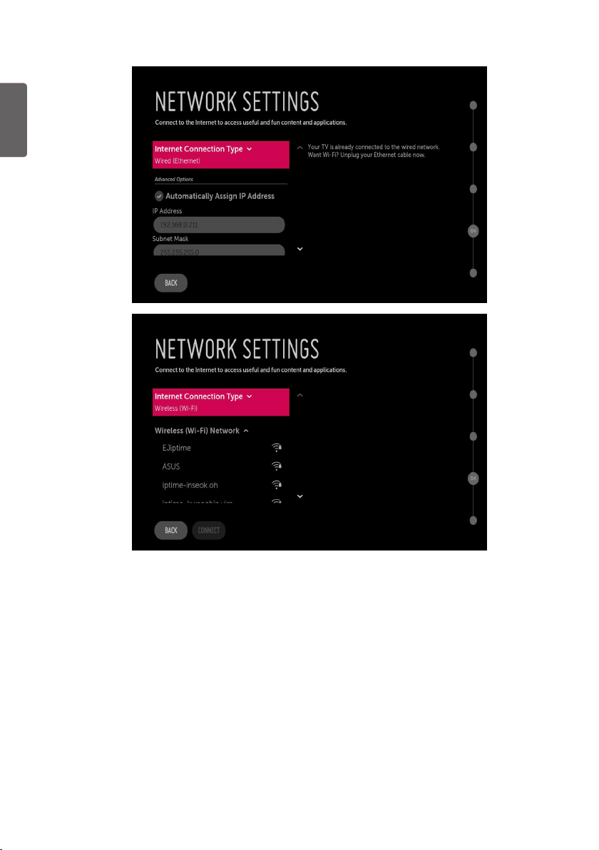
ENGLISH
ENG
• If you intend to set network, use the Network Settings option. You can connect easily to wired/
wireless network by this option. (page. 19)
6
Page 7
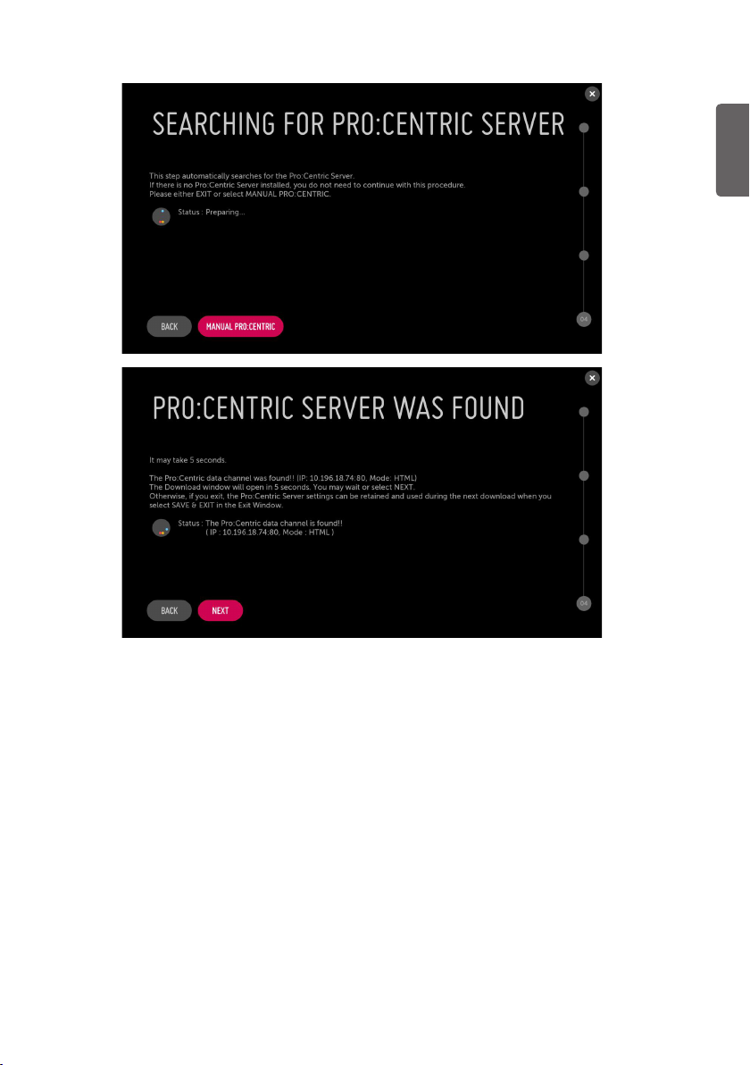
ENGLISH
2 This step automatically searches for the Pro:Centric Server. If was found the Pro:Centric data
channel, select the NEXT.
7
Page 8
ENGLISH
ENG
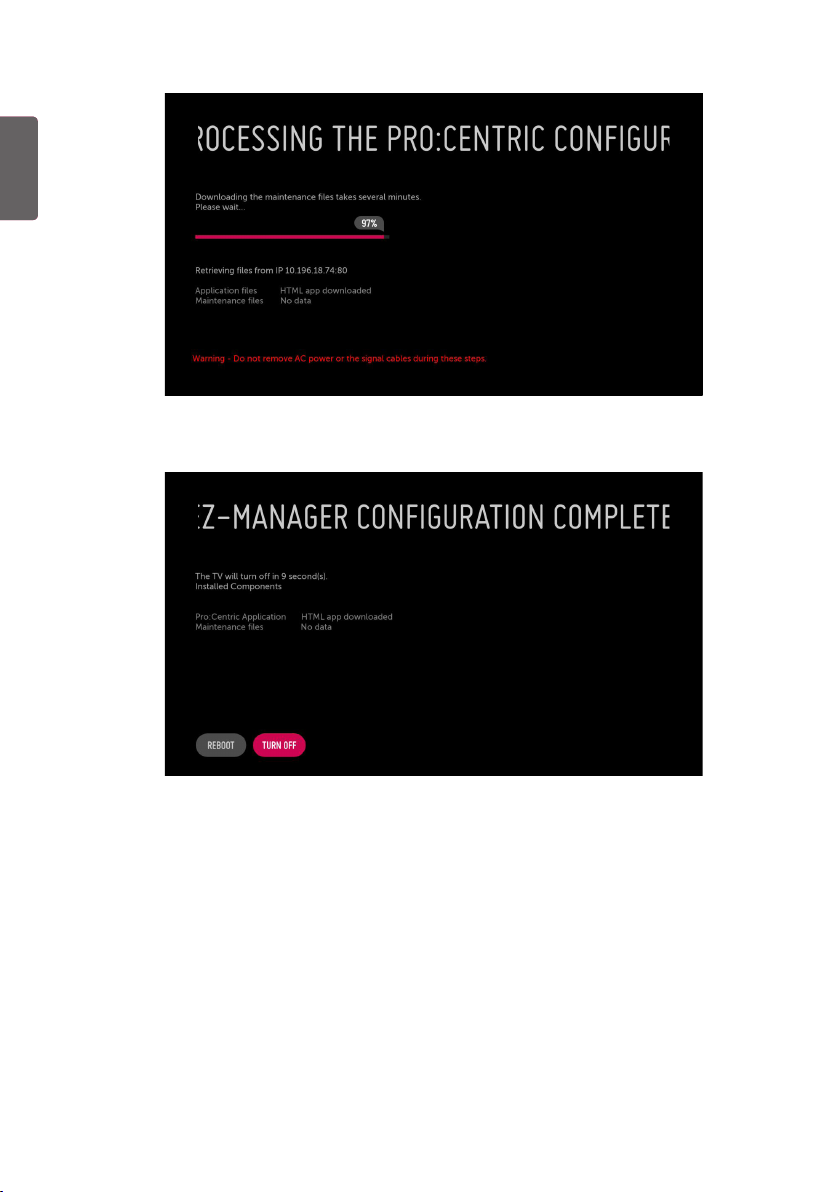
3 Downloading the Pro:Centric application files takes few minutes.
4 After the installation is completed, the following screen will be displayed.
8
Page 9
Manually for Setup
1 Select a Label and/or enter the Room Number using the numeric keypad on the remotes or
using the virtual keyboard on the TV screen. To continue, move and select NEXT.
ENGLISH
2 Please select the MANUAL PRO:CENTRIC.
9
Page 10
ENGLISH
ENG
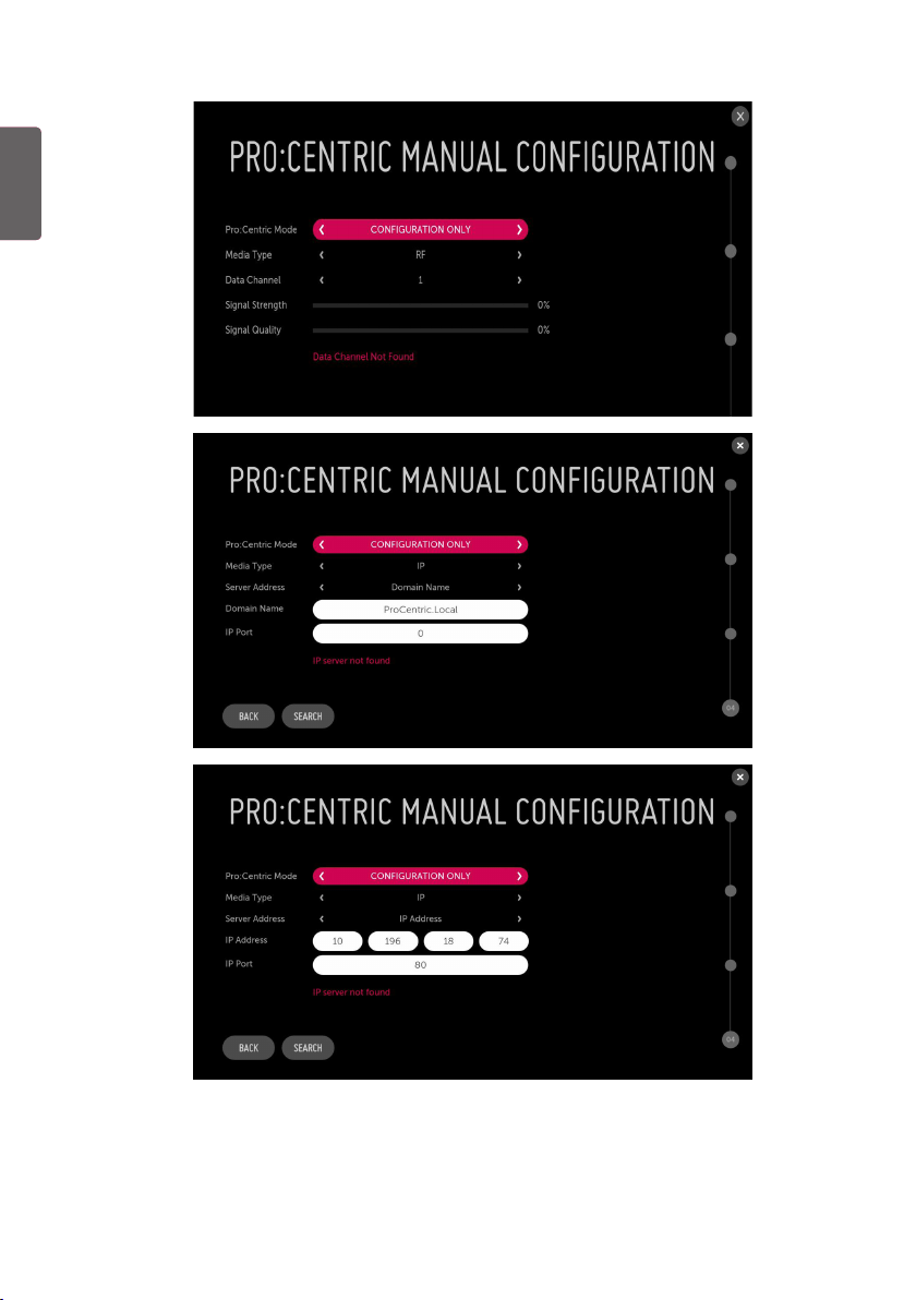
3 Configure the appropriate Pro:Centric settings in the TV.
10
Page 11
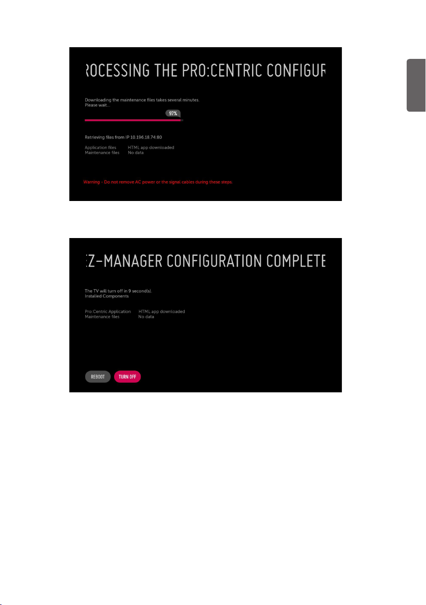
4 Downloading the Pro:Centric application files takes few minutes.
ENGLISH
5 After the installation is completed, the following screen will be displayed.
11
Page 12
ENGLISH
ENG
USB LG Smart Install Utility
1 Select the USB CONFIGURATION > TV MANAGER.
- If you have USB Memory for ‘LG_DTV’ or ‘lg_dtv’ folder, this step shows the USB file list for
downloading the items.
2 Downloading the files takes few minutes.
12
Page 13
3 After the installation is completed, the following screen will be displayed.
INSTALLATION MENU
Introduction
The abundant functions for Hotel TV linked with software installation can be projected on OSD as
Public Display Settings.
The wide range of hotel features can be performed simply on additional window to enhance the LG
hotel TV’s easy installation and convenient operation for Hotelier and System Integrators.
* Image shown may differ from your TV.
ENGLISH
TV
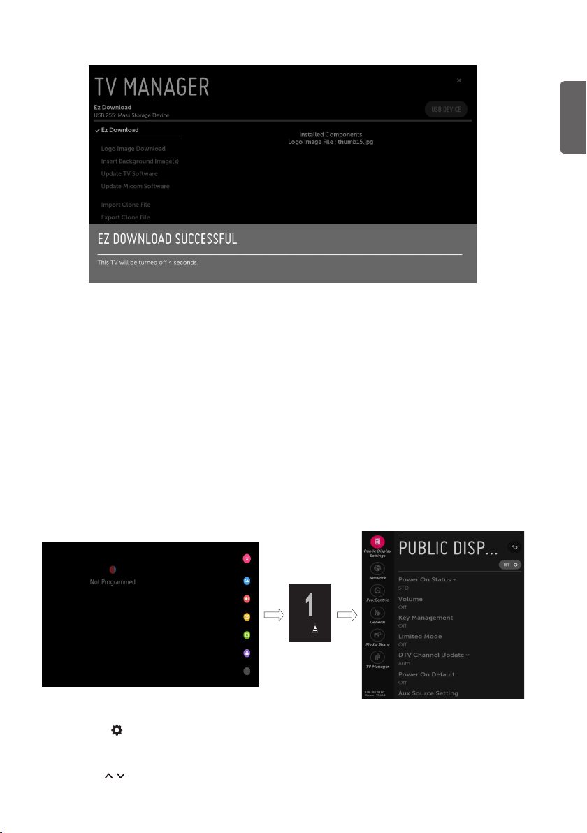
1 Press the (Settings) button for more than 5 seconds using the user remote control, channel
information will appear at top left on the screen.
2 Enter a four digit password and press OK button. The TV is set with the initial password “1-1-0-5”.
3 Use the button to select the desired menu.
13
Page 14
PUBLIC DISPLAY SETTINGS
ENGLISH
ENG
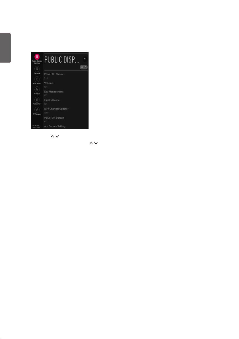
* Image shown may differ from your TV.
1 Use the button to select the Public Display Settings.
2 Use the OK button and then button to select Public Display Mode.
- When Public Display Mode is set to ON (Work), all functions of Public Display Mode apply.
Public Display Settings Operation
• Decide to work all functions of Public Display Settings or not by setting Public Display Settings
as ON (Work) or OFF (Do Not Work)
• When Public Display Settings is set to ON (Work), all functions of Public Display apply.
• When Public Display Settings is set to OFF (Do Not Work), all functions of Public Display don’t
apply.
• When it is set to ON, Key Lock item of the User menu is disabled and the OSD is displayed same to
the Local Key Operation setting of the Public Display Mode.
• When it is set to ON, all items reserved at the Schedule list are deleted and the reservation
function is not supported. (Applied for the model offering the reservation function)
• The TV triggered by the external device (ex: SIMPLINK, TV Link-Tuner, etc.) operates separately
from the Public Display Settings.
• When it is set to ON, User Menu > General > Reset to Initial Settings is disabled.
• When Public Display Settings is set to ON (Work), all skipped programs are not tuned by number
keys.
• When Public Display Settings is set to ON (Work), Detailed Information about the Channel is not
available in the EPG.
14
Page 15

Power On Status
• Decide to select working status of TV Set when turn on main power.
• You can set with PWR, STD, LST.
• PWR always make TV set On status when turn on main power .
• STD make Stand-by status when turn on main power.
• LST make TVSet work like previous power status. As same concept as Power Backup mode; If main
power were turned off in Power On status, TVSet would work in On status. If main power were
turned off in Stand-by status, TVSet would work in Stand-by status.
• If there Block All is both IR Operation and Local Key Operation from Key Management, In order
to provide the option that must be able to turn on the TV in the TV turned off situation, change
the value of the PWR. (Reference the Key Management)
Volume (0 ≤ Min ≤ Start ≤ Max ≤ 100)
• Decide to apply volume policy of Start Volume, Maximum Volume and Minimum Volume
as On (Work) or Off (Do Not Work).
Start Volume
This entry sets the start volume level when is power on.
• The level is specified as a number between minimum volume to maximum value.
(Min ≤ Start ≤ Max)
• The default setting is Off (disabled).
• When enabled, if the value is lower then the minimum specified in the minimum
volume entry, the minimum volume entry must be used.
• When enabled, if the value is larger then the maximum specified in the maximum
volume entry, the maximum volume value must be used.
• Access to a volume in Timer Power On of User Menu must be fixed to start volume
when HTNG HotelMode (Enable) and Start Volume (Off, 0 ~ 100) were set
simultaneously.
ENGLISH
Maximum Volume
This entry sets the Maximum Volume level the set.
• The level is specified as a number between Minimum Volume to 100. (Min ≤ Max ≤
100)
• If the command volume up to higher than maximum volume is received, that should be
ignored.
• The default value is 100.
Minimum Volume
This entry sets the Minimum Volume level the set will produce.
• The level is specified as a number between 0 to Maximum Volume. (0 ≤ Min ≤ Max)
• If the command volume down to lower than minimum volume is received, that should
be ignored.
• The default value is 0.
15
Page 16

ENGLISH
ENG
Key Management
• Manage key usability of Local(Front) Key and Remote Control. When selected to On, following IR
Operation and Local Key Operation will be worked by below.
IR Operation
Decide whether work the LG remote control or not.
• When IR Operation is set to Normal, all remote keys are available.
• Use PWR Only makes block all remote keys except power key.
• When IR Operation is set to Block All, all normal remote keys don’t work.
Local Key Operation
Decide to operate Local/Front Key working behavior by setting Local Key Operation as
Normal, Use PWR Only, Block All
• When Local Key Operation is set to Normal, all local key are available.
• Use PWR Only makes block all local keys except power key.
• When Local Key Operation is set to Block All, all local keys don’t work.
Limited Mode
Configure TV function’s limitation. When selected to On, following sub-menus will be worked by
below.
Setup Menu
Permit to tune and manage Channels as On (Permitted) or Off (Not permitted).
16
Channel Change
Decide to change channel or not by setting Channel Change as On (Change Possible) or
Off (Change Impossible) when present source is TV.
• When Channel Change is set to Off (Change Impossible)
- Channel Key, Numeral Key, List Key, Flash back Key don’t work and entering channel
Menu in the Main Menu OSD is impossible.
- Channel item in Timer Power On of User menu will be fixed.
- Entering Channels of User Menu is impossible regardless of Channels item of User
Menu.
• When Channel Change is set to On (Change Possible), Channel Key, Numeric Key, List
Key, Q.View Key, TV/RAD Key does work and entering Channel Menu in the Main Menu
OSD is possible.
Page 17

Menu Display
Function to decide whether work with menu (including relevant menus too) of control
key (On – Enter possible) or not (Off – Enter Impossible).
• Although select Off (Enter impossible), the action that press a Menu button for 5
seconds to enter installation menu is available.
• When select On (Enter possible), Menu works.
OSD Display
Decide to display OSD or not by setting OSD Display as On (Display) or Off (Do not
Display).
• When OSD Display is set to Off (Do not Display), all OSD is not displayed except some
exception.
• Although select Off (Do not Display), the action that press a menu button for 5 seconds
to enter installation menu and entering service menu are available. (In-Start, PowerOnly, Adjust, Installation Menu …)
System Provider Mode
System Provider Mode allows access to the menu system from the front panel or remote
control but access is controlled as follows:
• When value is On, Accessible Items on the menu system, others are not permissible.
- Input select screens
- Sleep Timer
- Aspect Ratio
- Closed Caption
- Safety / My Media / Network / About This TV
• If the channel map is empty, Auto-tuning guide dialog should be blocked by pressing
List, Fav, CH+ (Page up), CH- (Page down) keys.
ENGLISH
DTV Channel Update
It is a mode to set whether to update DTV channel information automatically or not.
• When DTV Channel Update is set to Auto, the function to update TV’s channel map according to
DTV channel’s stream information
• DTV Channel Update is set to Manual, the function to keep TV’s channel map even though DTV
channel’s information is changed.
17
Page 18

ENGLISH
ENG
Power On Default
Set the channel to display and Volume Level, etc. when turn on power in AC Power On or Stand-by
status.
• Set to On (Work) or Off (Do Not Work).
• When Power On Default is set to Off, it is not applied to the subordinate Input, Channel, A/V
Setting, Aspect Ratio menu.
• When Power On Default is set to On, it can set by entering the subordinate menu.
Input
Set whether it is turned on by the set input source or by the last stored input source.
Channel
Select start channel number if Input source’s value is TV.
A/V Setting
If A/V Setting is changed from Off to On, A/V parameters that are set before entering
installation menu are applied whenever turn on power.
Aspect Ratio
The aspect ratio determines the default aspect ratio that the set returns to on power up.
Aux Source Setting
The Auxiliary (Input) Source Setting feature will enable or disable for each external input.
• Set to On (Work) or Off (Do Not Work).
• User cannot disable the current input’s Aux Source Setting.
Power Management
The Power Management feature will turn off the television receiver if no input control command is
received from either the Local or IR Key within a selected hours.
• Activity on either of these inputs shall restart the Power Management timer and check key time
interval again.
• This entry can be set to a value which is corresponding to the desired hours (1 to 7).
• Default value is Off (disabled).
Factory Reset
Change all settings to their default values.
18
Page 19

NETWORK
1 Use the button to select the Network.
MAC Address
Displays the MAC address. (Not customizable).
Network Setting
One-click network connection
• Connects easily to a wired/wireless network.
• Network Connection to connect to an available network automatically. Follow the prompts on the
TV.
ENGLISH
To connect to a network through Set Expert
• For use in special circumstances such as in offices (in cases where a static IP is used).
1 Select a network connection, either Wired or Wireless.
2 When connecting via Wired, Configures the IP settings of the TV set. You can set the IP address,
subnet mask, gateway and DNS server.
3 When connecting via Wi-Fi, use the one of the following network connection methods.
AP List Connects to the network selected from the AP List.
Enter the SSID Connects to the wireless AP typed in.
WPS-PBC Connects easily when the button of a wireless AP supporting PBC is pressed.
WPS-PIN Connects easily when the PIN of the wireless AP that you wish to connect to
Advanced Wi-Fi
Settings
is entered in to the AP website.
After connects Wi-Fi, you can set the IP address, subnet mask, gateway and
DNS server.
19
Page 20

ENGLISH
ENG
LG Connect
* Depending upon model
Sets the LG Connect function to on or off.
• You can connect TV via LG TV Plus app in smart device.
• Default setting is On.
IP Stream Control
Audio PTS Offset
- Controlling output stream timing of audio.
- You can set the ‘-500 ~ 500’ (Change step is -10 or +10)
Video PTS Offset
- Controlling output stream timing of audio.
- You can set the ‘-500 ~ 500’ (Change step is -10 or +10)
IGMP
- You can set IGMP version. (2 or 3)
Wake On LAN
Sets the Wake On LAN function to Enable or Disable.
• The Wake On LAN feature enables the TV to receive software updates and/or be powered On
upon receipt of Wake Up Frame packets and/or Magic Packet data via the wired LAN. To facilitate
use of this feature, note that the appropriate wired connection must be made. (Wake up Frame
depends upon model)
20
Page 21

PRO:CENTRIC
1 Use the button to select the Pro:Centric.
Mode
Sets whether or not enable Pro:Centric and the service method.
• You can set to Off, Configuration Only, FLASH, GEM or HTML using the button. The default
value is Off; when it is set to Off, all the sub items are disabled. (Except for Update Event, Room
Number Setting)
Update Event
When Update Event is set to Enable, an Update Time field is displayed on the screen.
• Based on Update Time settings, the Wake for Update feature wakes the TV once daily to check for,
and if applicable, download updates from the Pro:Centric server.
ENGLISH
21
Page 22

ENGLISH
ENG
Media Type
Sets the medium type to RF or IP. The default value is RF.
RF
• Data Channel
- Sets the Channel at which the Pro:Centric data is received.
IP
• P:C IP Setting
- Server Address is set to IP Address
(IP Address) Set IPv4 address in 4 octets.
(Port Number) Sets the actual port or number where the Pro:Centric server is running.
- Server Address is set to Domain Name
(Domain Name) Sets the domain name where the Pro:Centric server is running.
(Port Number) Sets the actual port or number where the Pro:Centric server is running.
* The default value of IP a/b/c/d is 0 and the range is between 0 and 255. The default value of
Port is 0 and the range is between 0 and 65535.
Room Number Setting
You can set or change Label and Room Number using the Room Number Setting.
• Press the OK button in Room Number Setting item to go to the Change a room number menu.
22
Page 23

GENERAL
Conguration Setup
(1) Select RCU
It is a mode to set whether to use Select RCU or not. When Select RCU is set to Enable, You can
adjust Number of RCU menu.
(2) Number of RCU
It is a mode to set Number of RCU.
• Number of RCU value range 1~9. (When Select RCU is set to Enable.)
• Number of RCU value range 0. (When Select RCU is set to Disable.)
* RCU(Remote Control Unit) : It is special RCU that operates only setted number of RCU in TV.
(3) DTV Channel Update
It is a mode to set whether to update DTV channel automatically or not.
• When DTV Channel Update is set to Auto, the function to update TV’s Channel map according to
DTV channel’s stream information.
• DTV Channel Update is set to Manual, the function to keep TV’s channel map even though DTV
channel’s information is changed.
(4) On Timer Operation
It is a mode to select On Timer Operation working one time or repeatedly.
- Once: On Time in the user menu operates only one time when the On Time menu is set to On.
- Repeat : On Time operates repeatedly when the On Time menu is set to On.
(5) 15Min Auto Off
• When 15Min Auto Off is set to On, TV will turn off if there is no signal in 15Min.
ENGLISH
23
Page 24

ENGLISH
ENG
(6) Auto Sensing
• If Auto Sensing is set to On, the input is automatically switched when the input signal that you
set to On is received.
• If Auto Sensing is set to Off, the input is not switched when the input signal is received.
• SIMPLINK and Auto Sensing cannot work simultaneously. If SIMPLINK is set to On, Auto Sensing
is automatically set to Off.
• If the signal is removed while Auto Sensing (automatic input switch) is enabled, the input returns
to the previous setting. If the several inputs are connected by enabling Auto Sensing and the
automatic input switch is performed several times, the input returns to the previous setting only
for the last input and does not repeat the operation for the rest.
(7) Instant On
Set to Instant On Mute mode or Instant On Reboot mode to enable the Instant On feature. The
Instant On feature allows the TV to turn on when AC power is applied, but with video and audio
muted (Muted on). The TV retains its on status while appearing to be off. Pressing the Power button
toggles Off/On the video and audio mutes, so that the TV appears to turn on instantly.
(8) Insert Image
Set to Enable (Work) or Disable (Do Not Work).
• It is a mode to decide whether to display background image when using Bluetooth Sound Sync
app or watching Radio channel.
• You can download the background image at TV Manager app.
(9) No Signal Image
* Depending upon model
• Set to On or Off.
• It is a mode to decide whether to use no signal image when there is no signal.
External Speaker
* Depending upon model
(1) Volume Control
Selects the volume control method of an external speaker.
• You can select Off, Int Variable, Fixed., Ext Variable by pressing button.
• Ext Variable uses the External Vol Up/Down Control Line to change the volume up to 1 Watts.
• Int variable is linked to the main volume OSD and change the volume 0 - 1 Watts.
• Fixed produces a fixed output. The default is Off.
(2) Output
• This item is enabled when Volume Control is set to Fixed. You can choose one of 7 steps.
(0.01/0.03/0.05/0.1/0.2/0.5/1 Watts). The Default is 1 Watt.
Set ID Setup
(1) Set ID Lock
Set the Set ID item in General Menu whether to activate or not.
• Set to On (Work) or Off (Do Not Work).
(2) Set ID
• Set the Set ID of TV Set with 1~99.
24
Page 25

Power Saving
Static Saving
It is the item for setting the level to reduce the backlight control from the items for saving the
consuming power, which is increased or decreased by 10 steps from 0 to 100. 100 makes the
consuming power set to the same one from the TV. 0 reduces the consuming power to the
minimum. The default value is 100.
• The value displayed at the OSD is not changed and only the actual setting value is
converted to percentage based on the static saving value to set.
• 0 ~ 30: HIGH, 40 ~ 60 : MID , 70 ~ 90 : LOW , 100 : OFF
Keyless Off Hours
Automatically TV will be turned off if there is no key input for the preset time period.
• When it is set to Enable, User Menu -> Timer -> Auto Power Off is disabled.
• When it is set to Enable, User Menu -> Timer -> 2Hour Auto Power Off is disabled.
HCEC Setup
CEC Mode
* (Depending upon model)
You will have 3 modes to choose Default, HCEC and TVLink-CEC.
• If Default is selected, you can use SIMPLINK which is provided in LG TV. Also you can
enable and disable SIMPLINK through SIMPLINK MENU.
• If HCEC is selected, you can use TVLink-HCEC Protocol. For more detailed information,
please refer to TVLink-HCEC Protocol document)
• If TVLink-CEC is selected, TV will not directly work for key input except for power key. And
volume related keys will work just in case of Follower volume control mode. (for more
detailed information regarding the scenario of volume control, please refer to ‘TVLink-CEC
protocol’ document)
IR Decoding
• When IR Decoding is set to Enable, the TV decodes and changes it into a CEC Message and
sends it to Command via the HDMI CEC Line. The default value is Disable.
Device ID
• Sets the ID of a device(Logical Address) connected to the CEC Line. You can choose
between All and E.
• The default value is All.
StandBy
• Set the sending and receiving scenario of StandBy (0 x 0c) command.
• The detailed scenario is described on the table below.
ENGLISH
Send Receive
Send Only O X
Receive Only X O
All O O
Off X X
25
Page 26

ENGLISH
ENG
Forced Initialize
• This setting will be enabled When CEC mode is set as TVLink-CEC.
• If Enable is selected, TV will change its input source to HDMI1 by any HDMI-CEC simulation
from a device.
HTNG Public Display Mode
• If the following options are selected because of the HTNG command:
* Power On Default, Start Volume, Maximum Volume, Minimum Volume, then the value
for the HTNG Public Display Mode changes automatically to Enable and, even if the Public
Display Mode is set to Disable, the above options are still affected.
• If you change it to Disable, then the values set by the HTNG will be canceled.
Clock Setup
Clock Source
You can select Off, Pro:Centric, TV, NTP, Admin by pressing button.
- NTP : Clock is synchronized using Network Time Protocol. It’s only enabled when network
cable is connected.
- Admin : It’s automatically set to Admin when clock is updated by commercial protocols
like TVLink-HCEC, TVLink-Interactive, or HCAP API.
- Off : Clock is synchronized using any available clock source.
- Pro:Centric : Clock is synchronized using Pro:Centric server. (Depending upon model)
- TV : Clock is synchronized using particular TV program.
Input
- You can select Input according to Clock Source.
- You can select RF or IP when Clock Source is Pro:Centric.
- You can select TV source when Clock Source is TV.
- Input is set to None, HCAP, Protocol, HTNG automatically when Clock Source is Admin.
Program/Frequency (Depending upon model)
- Sets the Frequency to get the time information when Clock Source is Pro:Centric.
- You can select Program when Clock Source is TV.
Timezone(City) / Timezone(Custom) / Timezone(Offset) (Depending upon model)
- In the case when there is difference between the time information received from the
Teletext and the time of the current area, it can be set up to correct this. The initial value
is 0, and it can be changed in the range of -12Hrs ~ +14Hrs. (Timezone(Offset) range is
-12Hrs ~ +12Hrs)
Password Change
To ensure more security, Password can be changed by installers’ own design.
1 Change password by using virtual keyboard.
2 Input the password again for confirmation.
26
Page 27

Preloaded App
1 If you want to use a particular app, you can choose from the menu. you can setting each apps
activation.
2 You can check or uncheck by pressing OK button.
Lock Mode
If Lock Mode is Yes, the following features will be unavailable.
USB
• If it is set to Enable, USB devices do not work in relative features. (Exclude S/W update).
Factory Reset
• If it is set to Enable, User Menu > General > Reset to Initial Settings is disabled.
MEDIA SHARE
ENGLISH
* You can setting Whether to use for SmartShare.
SmartShare
• Smart Share enables DLNA function. If this value is enabled, TV act as Digital Media Player
(DMP) and display Digital Media Service(DMS) contents through Smart Share app.
Screen Share
• Screen Share enables WiFi p2p functions such as Miracast and WiDi. If this value is enabled,
Screen Share app is displayed at launcher bar and User can connect to TV by user’s Miracast
enabled mobile phone or WiDi enabled laptop.
27
Page 28

ENGLISH
ENG
Media Renderer
• Media Renderer enables the TV to act as a Media Renderer device to receive content from
DLNA Certifi ed devices on the same network.
DIAL
• With this DIAL service, you can launch the target app at Smart Home Launcher bar without
select the target app by remote controller. The target app should be already selected at
Installer Menu > General > Preloaded App.
TV Name
• When other media device (ex: smart phone, desktop, laptop) searching TV, this string was
displayed.
SoftAP
- If you want to use SoftAp menu on Media Share menu, you must select On in this item. The
SoftAP is a function of TV which is used like Access Point.
- Regardless of the Instant On mode, the SoftAP setting stays unchanged after power off/on.
(Depending upon model)
• Use Default
- If you want to use default password (this password was generated randomly), you must
select Enable in this item.
• Security Key
- When guests want to use TV’s SoftAP function, they need this password. If you want to
change this default password, you need to Change Use Default value into Disable.
• Wi-Fi Signal Strength
- You can control wireless signal strength on SoftAP mode. This is controlled by 5 step. If
you select Not Used, wireless signal strength will be set to Max value.
• Wi-Fi Channel
- You can control wireless channel on SoftAP mode. This is controlled from 1 to 11
channel. If you select Auto, wireless channel of SoftAP will be set to random channel.
28
Page 29

TV MANAGER
USB Download Menu
USB Cloning
An Installer can quickly set up and clone multiple TV sets at a property. These cloned TVs will
all have the same Master TV Setup: Public Display Settings, Installation menu settings, User A/V
settings and the Channel Map. This newer procedure significantly decreases the installation time
that would be necessary if the standard RS-232C method were used instead.
(1) Overview USB Cloning Procedure
• Commercial TVs have the capability to support cloning internal TV data and Channel information
with an external clone device called USB Cloning, in order to copy TV data accurately and
quickly. The clone internal functions use slightly different internal processes for the two types
of commercial TVs. However, the UI of cloning feature remains the same in both. Regarding the
demands over the current cloning feature for quicker cloning, better portability and etc, we
would like to announce the cloning process via USB port, named as USB Cloning. USB cloning
process is divided into 2 main processes. One is writing the previously saved TV data into the
TV, and one another is reading of current TV data into USB memory card. To avoid any confusion
due to the words, it is clearly specified as Import Clone File and Export Clone File in the whole
process.
(2) Data To Be Cloned
• The data cloned are the same data cloned by previous USB Cloning. Details are explained in the
following:
- 1. TV data includes:
A. Installer Menu settings
B. Main menu settings (Audio, Picture etc)
- 2. Analog / Digital Channel information includes:
A. Channel numbers
B. Channel label
C. Channel attributes including channel type, skipping status and etc.
ENGLISH
29
Page 30

Ez Download
ENGLISH
ENG
• Ez Download is a function that enables users to download the desired items all at once, such as
EPK (software update file), TLL, Logo Image, Background Images, Micom.
- Images and EPK files should be copied into the folder named LG_DTV on the USB.
• TLL files should be copied to the root folder of the USB.
• If you press Ez Download menu, Ez Download is launched.
• If .DZM file exist file will be selected previously download file.
NOTE
• If the DZM file is still in the USB after the download is complete:
An Ez Download pop-up window will appear and list the file types, such as TLL, Logo Image,
Background Images, EPK or Micom with the previously downloaded lists checked automatically.
30
Page 31

Logo Image Download
• If there are more than two USB Memory Device, It is possible to select the USB.
• The download sequence is Logo Image Download > Select Images > UPDATE.
NOTE
• Splash Image update function supports only JPEG, BMP format file of less than 8 MB file size.
• We recommend you that splash image resolution match the TV`s panel resolution.
• Max resolution of splash image : Full HD > 1920 x 1080, HD > 1360 x 768.
• Min resolution of splash image : Full HD > 64 x 64, HD > 64 x 64.
• TV keep splash image until you change a new splash image.
• The target file is located in ‘LG_DTV’ folder.
ENGLISH
31
Page 32

ENGLISH
ENG
Insert Background Image(s)
• This feature downloads Insert Background Image(s) from USB.
• Images should be copied to ‘LG_DTV’ of the USB.
• The download sequence is Insert Background Image(s) > Select Images > UPDATE.
NOTE
• Maximum number of images that you can update at once are 12.
• If you updates the images, original images will be removed.
• Insert Background Image update function supports only JPEG, BMP format file of less than 10 MB
filesize.
• Max resolution of splash image : Full HD > 1920 x 1080, HD > 1360 x 768.
• Min resolution of splash image : Full HD > 64 x 64, HD > 64 x 64.
• If you want to use inserted image in Bluetooth Sound Sync app and Live TV’s Radio Programme,
please change the value of Insert Image property to enable (Insert Image in Installation >
General > Configuration Setup).
32
Page 33

Update TV Software
• This feature updates TV software through the EPK file in USB. The target file is located in
‘LG_DTV’ folder.
• If there are more than two USB memory Device, It is possible to select the USB.
• The download sequence is Update TV Software > Select file(EPK) > UPDATE.
Update Micom Software
ENGLISH
• This feature updates Micom software through the txt file in USB. The target file is located in
‘LG_DTV’ folder.
• If there are more than two USB memory Device, It is possible to select the USB.
• The download sequence is Update Micom Software -> Select file(txt) -> UPDATE.
33
Page 34

ENGLISH
ENG
Import Clone File
• Once the internal TV data and its channel map information is written to the USB memory card,
the user can start Import Clone File process with the data file generated and stored in USB
memory card. As previously warned in Export Clone File process, the user should not turn TV
off nor unplug the USB memory card. The following images might be slightly different than the
OSD image.
Export Clone File
• Export Clone File must be done first before Import Clone File process. While writing is in
process, the user must not turn TV off nor unplug the USB memory card. The following images
might be slightly different than the OSD image.
34
Page 35

Diagnostics
• Sets Enable or Disable. When it is set to Disable, user can’t control TV via RMS. The changed
setting is applied after reboot.
ENGLISH
35
Page 36

KEY CODES
ENGLISH
ENG
* This feature is not available for all models.
Code
(Hexa)
00
01
02 R/C Button 61
03 R/C Button 63
06 R/C Button 71
07 R/C Button 72
08
09 R/C Button 8E R/C Button
0B R/C Button 8F R/C Button
0C R/C Button 95 R/C Button
0F R/C Button AA R/C Button
10 - 19 Number Key 0 - 9 R/C Button AB R/C Button
1A R/C Button AF R/C Button
28 (Back) R/C Button B0 R/C Button
39 R/C Button B1 R/C Button
40 R/C Button B5 R/C Button
41 R/C Button BA R/C Button
43 R/C Button BB R/C Button
44 R/C Button
Function Note
/
/
(Power)
R/C Button 4C (Dash) / R/C Button
R/C Button 5B R/C Button
R/C Button 7C R/C Button
Code
(Hexa)
Function Note
(Blue)
(Yellow)
(Green)
(Red)
R/C Button
R/C Button
R/C Button
R/C Button
• Key code 4C (0 x 4C) is available on ATSC/ISDB models which use major/minor channel. (For South
Korea, Japan, North America, Latin America except Colombia models)
36
Page 37

EXTERNAL CONTROL DEVICE SETUP
USB IN
(TV)
(PC)
* Image shown may differ from your TV.
* Cable is not provided.
* The connection interface may differ from your TV.
RS-232C Setup
USB to Serial converter with USB Cable
USB Type
(PC)
• Connect the USB to Serial converter/RS-232C
input jack to an external control device (such
as a computer or an A/V control system) to
control the product’s functions externally.
• Connect the serial port of the control device
to the RS-232C jack on the product back
panel.
NOTE
• The type of control port on the TV can be
different between model series.
USB IN
(TV)
ENGLISH
• LG TV supports PL2303 chip-based (Vendor ID : 0 x 0557, Product ID : 0 x 2008) USB to serial
converter which is not made nor provided by LG.
• It can be purchased from computer stores that carry accessories for IT support professionals.
RS-232C with RS-232C Cable
DE9 (D-Sub 9pin) Type
RS-232C IN
(PC)
(CONTROL & SERVICE)
• You need to purchase the RS-232C (DE9, D-Sub 9 pin female-to-female type) to RS-232C cable
required for the connection between the PC and the TV, which is specified in the manual.
• The connection interface may differ from your TV.
(TV)
37
Page 38

ENGLISH
ENG
Connector type : D-Sub 9-pin male
1
5
6
RS-232C
(Serial port)
RS-232C configurations
7-Wire Configurations
(Standard RS-232C cable)
PC TV
RXD 2 3 TXD
TXD 3 2 RXD
GND 5 5 GND
DTR 4 6 DTR
DSR 6 4 DSR
RTS 7 8 RTS
CTS 8 7 CTS
D-Sub 9 D-Sub 9
9
3-Wire Configurations
(Not standard)
PC TV
RXD 2 3 TXD
TXD 3 2 RXD
GND 5 5 GND
DTR 4 6 DTR
DSR 6 4 DSR
RTS 7 8 RTS
CTS 8 7 CTS
D-Sub 9 D-Sub 9
Set ID
For Set ID number, see “Real data mapping (Hexadecimal : Decimal)”.
1 Press to access the main menus.
2 Press the Navigation buttons to scroll to (* General → Set ID) and press button.
3 Scroll left or right to select a set ID number and select (Back). The adjustment range is 1-99.
4 When you are finished, press .
38
Page 39

Communication Parameters
• Baud rate : 9600 bps (UART)
• Data length : 8 bits
• Parity : None
• Stop bit : 1 bit
• Communication code : ASCII code
• Use a crossed (reverse) cable.
Command reference list
* (Depending upon model)
COMMAND1 COMMAND2 DATA (Hexadecimal)
1 Power k a 00 to 01
2 Aspect Ratio k c (page 41)
3 Screen Mute k d (page 41)
4 Volume Mute k e 00 to 01
5 Volume Control k f 00 to 64
6 Contrast k g 00 to 64
7 Brightness k h 00 to 64
8 Color k i 00 to 64
9 Tint k j 00 to 64
10 Sharpness k k 00 to 32
11 OSD Select k l 00 to 01
12 Remote Control Lock Mode k m 00 to 01
13 Treble k r 00 to 64
14 Bass k s 00 to 64
15 Balance k t 00 to 64
16 Color Temperature x u 00 to 64
17 Equalizer j v (page 43)
18 Energy Saving j q 00 to 05
19 Tune Command m a (page 43)
20 Channel Skip/Add m b 00 to 01
21 Key m c Key Codes
22 Control Backlight m g 00 to 64
23 Input select x b (page 46)
24 Auto Configure j u (page 46)
ENGLISH
• During playing media, all commands except Power (ka) and Key (mc) are not executed and
treated as NG. With RS-232C cable, TV can communicate “ka command” in power-on or power-off
status. But with USB-to-Serial converter cable, the command works only if TV is on.
39
Page 40

TRANSMISSION / RECEIVING PROTOCOL
ENGLISH
ENG
* (Depending upon model)
Transmission
[Command1][Command2][ ][Set ID][ ][Data][Cr]
[Command 1] : First command to control the TV. (j, k, m or x)
[Command 2] : Second command to control the TV.
[Set ID] : You can adjust the set ID to choose desired monitor ID number in option menu.
Adjustment range is 1 to 99. When selecting Set ID ‘0’, every connected set is controlled. Set ID
is indicated as decimal (1 to 99) on menu and as Hexa decimal (0 x 0 to 0 x 63) on transmission/
receiving protocol.
[Data] : To transmit command data (hexadecimal). Transmit ‘FF’ data to read status of command.
[Cr] : Carriage Return - ASCII code ‘0 x 0D’
[ ] : Space – ASCII code ‘0 x 20’
OK Acknowledgement
[Command2][ ][Set ID][ ][OK][Data][x]
* The set transmits ACK (acknowledgement) based on this format when receiving normal data. At
this time, if the data is data read mode, it indicates present status data. If the data is data write
mode, it returns the data of the PC computer.
Error Acknowledgement
[Command2][ ][Set ID][ ][NG][Data][x]
* The set transmits ACK (acknowledgement) based on this format when receiving abnormal data
from non-viable functions or communication errors.
Data 00: Illegal Code
Real data mapping (Hexadecimal : Decimal)
* When you enter the [Data] in hexadecimal, refer to following conversion table.
* Channel Tune (ma) Command uses two-byte hexadecimal value([Data]) to select channel number.
00 : Step 0 32 : Step 50 (Set ID 50) FE : Step 254
01 : Step 1 (Set ID 1) 33 : Step 51 (Set ID 51) FF : Step 255
... ... ...
0A : Step 10 (Set ID 10) 63 : Step 99 (Set ID 99) 01 00 : Step 256
... ... ...
0F : Step 15 (Set ID 15) C7 : Step 199 27 0E : Step 9998
10 : Step 16 (Set ID 16) C8 : Step 200 27 0F : Step 9999
... ... ...
40
Page 41

1 Power (Command: k a)
►To control power on or off of the set.
Transmission
[k][a][ ][Set ID][ ][Data][Cr]
Data 00 : Off
Data 01 : On
Ack
[a][ ][Set ID][ ][OK/NG][Data][x]
►To show TV is power on or *off
Transmission
[k][a][ ][Set ID][ ][FF][Cr]
Ack
[a][ ][Set ID][ ][OK/NG][Data][x]
* Similarly, if other functions transmit ‘FF’ data
based on this format, Acknowledgement
feedback presents status about each
function.
* OK Ack., Error Ack. and other message may
display on the screen when TV is power on.
2 Aspect Ratio (Command: k c) (Main Picture
Size)
►To adjust the screen format. (Main picture
format) You can also adjust the screen
format using the picture settings.
Transmission
[k][c][ ][Set ID][ ][Data][Cr]
Data 01 : 4:3 (Normal screen - Just Scan Off)
Data 02 : 16:9 (Wide screen - Just Scan Off )
Data 06 : Original (Just Scan Off )
Data 09 : Just Scan
Ack
[c][ ][Set ID][ ][OK/NG][Data][x]
* Using the PC input, you select either 16:9 or
4:3 screen aspect ratio.
* In DTV/HDMI/Component mode (high-
definition), Just Scan is available.
* Full wide mode may work differently based
on model and is supported for DTV fully, and
ATV, AV partially.
3 Screen Mute (Command: k d)
►To select screen mute on/off.
Transmission
[k][d][ ][Set ID][ ][Data][Cr]
Data 00 : Screen mute off (Picture on) / Video
mute off
Data 01 : Screen mute on (Picture off)
Data 10 : Video mute on
Ack
[d][ ][Set ID][ ][OK/NG][Data][x]
* In case of video mute on only, TV will display
On Screen Display(OSD). But, in case of
Screen mute on, TV will not display OSD.
4 Volume Mute (Command: k e)
►To control volume mute on/off. You can
also adjust mute using the mute button on
remote control.
Transmission
[k][e][ ][Set ID][ ][Data][Cr]
Data 00 : Volume mute on (Volume off)
Data 01 : Volume mute off (Volume on)
Ack
[e][ ][Set ID][ ][OK/NG][Data][x]
5 Volume Control (Command: k f)
►To adjust volume. You can also adjust
volume with the volume buttons on remote
control.
Transmission
[k][f][ ][Set ID][ ][Data][Cr]
Data Min : 00 to Max : 64
Ack
[f][ ][Set ID][ ][OK/NG][Data][x]
6 Contrast (Command: k g)
►To adjust screen contrast. You can also
adjust contrast in the picture settings.
Transmission
[k][g][ ][Set ID][ ][Data][Cr]
Ack
[g][ ][Set ID][ ][OK/NG][Data][x]
ENGLISH
41
Page 42

ENGLISH
ENG
7 Brightness (Command: k h)
►To adjust screen brightness. You can also
adjust brightness in the picture settings.
Transmission
[k][h][ ][Set ID][ ][Data][Cr]
Data Min : 00 to Max : 64
Ack
[h][ ][Set ID][ ][OK/NG][Data][x]
8 Color (Command: k i)
►To adjust the screen color. You can also
adjust colour in the picture settings.
Transmission
[k][i][ ][Set ID][ ][Data][Cr]
Data Min : 00 to Max : 64
Ack
[i][ ][Set ID][ ][OK/NG][Data][x]
9 Tint (Command: k j)
►To adjust the screen tint. You can also adjust
colour in the picture settings.
Transmission
[k][j][ ][Set ID][ ][Data][Cr]
Data Red : 00 to Green : 64
Ack
[j][ ][Set ID][ ][OK/NG][Data][x]
10 Sharpness (Command: k k)
►To adjust the screen sharpness. You can also
adjust sharpness in the picture settings.
Transmission
[k][k][ ][Set ID][ ][Data][Cr]
Data Min : 00 to Max : 32
Ack
[k][ ][Set ID][ ][OK/NG][Data][x]
11 OSD Select (Command: k l)
►To select OSD (On Screen Display) on/off
when controlling remotely.
Transmission
[k][l][ ][Set ID][ ][Data][Cr]
Data 00 : Off
Data 01 : On
Ack
[l][ ][Set ID][ ][OK/NG][Data][x]
12 Remote Control Lock Mode (Command:
k m)
►To lock the front panel controls on the
monitor and remote control.
Transmission
[k][m][ ][Set ID][ ][Data][Cr]
Data 00 : Off
Data 01 : On
Ack
[m][ ][Set ID][ ][OK/NG][Data][x]
* If you are not using the remote control, use
this mode. When main power is off & on
(plug-off and plug-in, after 20 - 30 seconds),
external control lock is released.
* In the standby mode (DC off by off timer or
‘ka’, ‘mc’ command), and if key operation is
on, TV will not turn on by power on key of IR
& Local Key.
13 Treble (Command: k r)
(Depending upon model)
►To adjust treble. You can also adjust Treble
in the audio settings.
Transmission
[k][r][ ][Set ID][ ][Data][Cr]
Data Min : 00 to Max : 64
Ack
[r][ ][Set ID][ ][OK/NG][Data][x]
42
Page 43

14 Bass (Command: k s)
(Depending upon model)
►To adjust bass. You can also adjust Bass in
the audio settings.
Transmission
[k][s][ ][Set ID][ ][Data][Cr]
Data Min : 00 to Max : 64
Ack
[s][ ][Set ID][ ][OK/NG][Data][x]
15 Balance (Command: k t)
►To adjust balance. You can also adjust
balance in the audio settings.
Transmission
[k][t][ ][Set ID][ ][Data][Cr]
Data Min : 00 to Max : 64
Ack
[t][ ][Set ID][ ][OK/NG][Data][x]
16 Color Temperature (Command: x u)
►To adjust colour temperature. You can also
adjust color temperature in the picture
settings.
Transmission
[x][u][ ][Set ID][ ][Data][Cr]
Data Min : 00 to Max : 64
Ack
[u][ ][Set ID][ ][OK/NG][Data][x]
17 Equalizer (Command : j v)
►Adjust EQ of the set.
Transmission
[j][v][ ][Set ID][ ][Data][Cr]
MSB
LSB
0 0 0 0 0 0 0 0
Frequency Data
7 6 5 Frequency 4 3 2 1 0 Step
0 0 0 1st Band 0 0 0 0 0 0(decimal)
0 0 1 2nd Band 0 0 0 0 1 1(decimal)
0 1 0 3rd Band ... ... ... ... ... ...
0 1 1 4th Band 1 0 0 1 1 19(decimal)
1 0 0 5th Band 1 0 1 0 0 20(decimal)
Ack
[v][ ][Set ID][ ][OK/NG][Data][x]
* It depends on model, and can adjust when
sound mode is EQ adjustable value.
18 Energy Saving (Command: j q)
(Depending upon model)
►To reduce the power consumption of the
TV. You can also adjust energy saving in
picture settings.
Transmission
[j][q][ ][Set ID][ ][Data][Cr]
Data 00 : Off
Data 01 : Minimum
Data 02 : Medium
Data 03 : Maximum
Data 04 : Auto
Data 05 : Screen off
Ack
[q][ ][Set ID][ ][OK/NG][Data][x]
19 Tune Command (Command: m a)
* This command may work differently
Depending upon model and signal.
* For Europe, Mid-East, Colombia, Asia except
South Korea and Japan Model
►Select channel to following physical
number.
Transmission
[m][a][ ][Set ID][ ][Data 00][ ][Data 01]
[ ][Data 02][Cr]
• Analog Antenna/Cable
[Data 00][Data 01] Channel Data
Data 00 : High byte channel data
Data 01 : Low byte channel data
- 00 00 ~ 00 C7 (Decimal : 0 ~ 199)
Data 02 : Input Source (Analog)
- 00 : Antenna TV (ATV)
- 80 : Cable TV (CATV)
ENGLISH
43
Page 44

ENGLISH
ENG
• Digital Antenna/Cable/Satellite
[Data 00][Data 01]: Channel Data
Data 00 : High byte channel data
Data 01 : Low byte channel data
- 00 00 ~ 27 0F (Decimal: 0 ~ 9999)
Data 02 : Input Source (Digital)
- 10 : Antenna TV (DTV)
- 20 : Antenna Radio (Radio)
- 40 : Satellite TV (SDTV)
- 50 : Satellite Radio (S-Radio)
- 90 : Cable TV (CADTV)
- a0 : Cable Radio (CA-Radio)
• Tune Command Examples:
1 Tune to the Analog antenna (PAL)
Channel 10.
Set ID = All = 00
Data 00 & 01 = Channel Data is 10 = 00
0a
Data 02 = Analog Antenna TV = 00
Result = ma 00 00 0a 00
2 Tune to the digital antenna (DVB-T)
Channel 01.
Set ID = All = 00
Data 00 & 01 = Channel Data is 1 = 00 01
Data 02 = Digital Antenna TV = 10
Result = ma 00 00 01 10
3 Tune to the satellite (DVB-S)
Channel 1000.
Set ID = All = 00
Data 00 & 01 = Channel Data is 1000 =
03 E8
Data 02 = Digital Satellite TV = 40
Result = ma 00 03 E8 40
Ack
[a][ ][Set ID][ ][OK][Data 00][Data 01]
[Data 02][x][a][ ][Set ID][ ][NG][Data 00][x]
* For South Korea, North/Latin America except
Colombia Model
►To tune channel to following physical/
major/minor number.
Transmission
[m][a][ ][0][ ][Data 00][ ][Data 01][ ]
[Data 02][ ][Data 03][ ][Data 04][ ][Data 05][Cr]
- Digital channels have a Physical, Major, and
Minor channel number. The Physical number
is the actual digital channel number, the
Major is the number that the channel should
be mapped to, and the Minor is the subchannel. Since the ATSC tuner automatically
maps the channel from the Major / Minor
number, the Physical number is not required
when sending a command in Digital.
• Analog Antenna/Cable
Data 00 : Physical Channel Number
- Antenna (ATV) : 02~45 (Decimal:
2 ~ 69)
- Cable (CATV) : 01, 0E~7D
(Decimal : 1, 14~125)
[Data 01 ~ 04]: Major/Minor Channel
Number
Data 01 & 02: xx (Don’t care)
Data 03 & 04: xx (Don’t care)
Data 05: Input Source (Analog)
- 00 : Antenna TV (ATV)
- 01 : Cable TV (CATV)
• Digital Antenna/Cable
Data 00 : xx (Don’t care)
[Data 01][Data 02]: Major Channel Number
Data 01 : High byte Channel Data
Data 02 : Low byte Channel Data
- 00 01 ~ 27 0F (Decimal: 1 ~ 9999)
[Data 03][Data 04]: Minor Channel Number
Data 03 : High byte Channel Data
Data 04 : Low byte Channel Data
Data 05 : Input Source (Digital)
- 02 : Antenna TV (DTV) – Use
Physical Channel Number
- 06 : Cable TV (CADTV) – Use
Physical Channel Number
- 22 : Antenna TV (DTV) – Don’t
Use Physical Channel Number
- 26 : Cable TV (CADTV) - Don’t Use
Physical Channel Number
- 46 : Cable TV (CADTV) – Use
Major Channel Number Only (One
Part Channel)
44
* Two bytes are available for each major and
minor channel data, but usually the low byte
is used alone (high byte is 0).
Page 45

• Tune Command Examples:
1 Tune to the Analog cable (NTSC) channel
35.
Set ID = All = 00
Data 00 = Channel Data is 35 = 23
Data 01 & 02 = No Major = 00 00
Data 03 & 04 = No Minor = 00 00
Data 05 = Analog Cable TV = 01
Total = ma 00 23 00 00 00 00 01
2 Tune to the digital antenna (ATSC)
channel 30-3.
Set ID = All = 00
Data 00 = Don’t know Physical = 00
Data 01 & 02 = Major is 30 = 00 1E
Data 03 & 04 = Minor is 3 = 00 03
Data 05 = Digital Antenna TV = 22
Total = ma 00 00 00 1E 00 03 22
Ack
[a][ ][Set ID][ ][OK][Data 00][Data 01][Data 02]
[Data 03][Data 04][Data 05][x][a][ ][Set ID][ ]
[NG][Data 00][x]
• Tune Command Examples:
1 Tune to the digital antenna (ISDB-T)
channel 17-1.
Set ID = All = 00
Data 00 = Don’t know Physical = 00
Data 01 & 02 = Major is 17 = 00 11
Data 03 & 04 = Minor/Branch is 1 = 00 01
Data 05 = Digital Antenna TV = 02
Total = ma 00 00 00 11 00 01 02
2 Tune to the BS (ISDB-BS) channel 30.
Set ID = All = 00
Data 00 = Don’t know Physical = 00
Data 01 & 02 = Major is 30 = 00 1E
Data 03 & 04 = Don’t Care = 00 00
Data 05 = Digital BS TV = 07
Total = ma 00 00 00 1E 00 00 07
* This feature is varied based on the model.
Ack
[a][ ][Set ID][ ][OK][Data 00][Data 01]
[Data 02][Data 03][Data 04][Data 05]
[x][a][ ][Set ID][ ][NG][Data 00][x]
ENGLISH
* For Japan Model
►To tune channel to following physical/
major/minor number.
Transmission
[m][a][ ][0][ ][Data 00][ ][Data 01][ ][Data 02]
[ ][Data 03][ ][Data 04][ ][Data 05][Cr]
• Digital Antenna/Satellite
Data 00 : xx (Don’t care)
[Data 01][Data 02] : Major Channel Number
Data 01 : High byte Channel Data
Data 02 : Low byte Channel Data
- 00 01 ~ 27 0F (Decimal: 1 ~ 9999)
[Data 03][Data 04] : Minor/Branch Channel
Number (Don’t care in Satellite)
Data 03 : High byte Channel Data
Data 04 : Low byte Channel Data
Data 05 : Input Source (Digital/Satellite for
Japan)
- 02 : Antenna TV (DTV)
- 07 : BS (Broadcasting Satellite)
- 08 : CS1 (Communication Satellite
1)
- 09 : CS2 (Communication Satellite
2)
20 Channel Skip/Add (Command: m b)
►To skip current channel for next time.
Transmission
[m][b][ ][Set ID][ ][Data][Cr]
Data 00 : Del(ATSC,ISDB)/Skip(DVB)
Data 01 : Add
Ack
[b][ ][Set ID][ ][OK/NG][Data][x]
* Set the saved channel status to del(ATSC,
ISDB)/ skip(DVB) or add.
21 Key (Command: m c)
►To send IR remote key code.
Transmission
[m][c][ ][Set ID][ ][Data][Cr]
Data : Key code - page 36
Ack
[c][ ][Set ID][ ][OK/NG][Data][x]
45
Page 46

ENGLISH
ENG
22 Control Backlight (Command: m g)
►To control the backlight.
Transmission
[m][g][ ][Set ID][ ][Data][Cr]
Data Min : 00 to Max : 64
Ack
[g][ ][Set ID][ ][OK/NG][Data][x]
23 Input select (Command: x b) (Main Picture
Input)
►To select input source for main picture.
Transmission
[x][b][ ][Set ID][ ][Data][Cr]
Data 00 : DTV
Data 01 : CADTV
Data 02 : Satellite DTV ISDB-BS (Japan)
Data 03 : ISDB-CS1 (Japan)
Data 04 : ISDB-CS2 (Japan)
Data 10 : ATV
Data 11 : CATV
Data 20 : AV or AV1
Data 21 : AV2
Data 40 : Component1
Data 41 : Component2
Data 60 : RGB
Data 90 : HDMI1
Data 91 : HDMI2
Data 92 : HDMI3
Data 93 : HDMI4
Ack
[b][ ][Set ID][ ][OK/NG][Data][x]
* This function depends on model and signal.
24 Auto Configure (Command: j u)
(Depending upon model)
►To adjust picture position and minimize
image shaking automatically. It works only
in RGB (PC) mode.
Transmission
[j][u][ ][Set ID][ ][Data][Cr]
Data 01 : To set
Ack
[u][ ][Set ID][ ][OK/NG][Data][x]
46
Page 47

 Loading...