

LG LM-K3960X, LM-K3365X User Manual
Please read this manual carefully before operating your set.
Retain it for future reference.
Designs and specifications are subject to change without
notice for improvement.
The working life of this product is 7 years since the date of
purchase.
MOSCOW_LM-K3960(K3960Q)/K3961(KW3960Q)/K3965(K3860Q)/K3565(K3565Q)/
K3365(K3365Q)_ENG_MFL39518829
CD - R/RCD - R/RW
KARAOKE MINI HOME THEATER
OWNER’S MANUAL
MODEL : LM-K3960Q
(LM-K3960, LMS-K3960V)
LM-KW3960Q
(LM-KW3960, LMS-KW3960V)
LM-K3860Q
(LM-K3860, LMS-K3860V)
LM-K3565Q
(LM-K3565, LMS-K3565V)
LM-K3365Q
(LM-K3365, LMS-K3365V)
USB
2
Safety Precautions
This lightning flash with arrowhead symbol within an
equilateral triangle is intended to alert the user to
the presence of uninsulated dangerous voltage
within the product’s enclosure that may be of
sufficient magnitude to constitute a risk of electric
shock to persons.
The exclamation point within an equilateral triangle
is intended to alert the user to the presence of
important operating and maintenance (servicing)
instructions in the literature accompanying the
appliance.
CAUTION: Do not block any ventilation openings. Install in
accordance with the manufacturer's instructions.
Slots and openings in the cabinet are provided for ventilation
and to ensure reliable operation of the product and to protect it
from over heating.
The openings should be never be blocked by placing the product on a bed, sofa, rug or other similar surface. This product
should not be placed in a built-in installation such as a bookcase or rack unless proper ventilation is provided or the manufacturer's instruction have been adhered to.
CAUTION:
This Product employs a Laser System.
To ensure proper use of this product, please read this owner’s
manual carefully and retain for future reference, should the unit
require maintenance, contact an authorized service locationsee service procedure.
Use of controls, adjustments or the performance of procedures
other than those specified herein may result in hazardous
radiation exposure.
To prevent direct exposure to laser beam, do not try to open
the enclosure. Visible laser radiation when open. DO NOT
STARE INTO BEAM.
CAUTION: The apparatus shall not be exposed to water,
dripping or splashing and that no objects filled with liquids,
such as vases, shall be placed on the apparatus.
CAUTION:
VISIBLE AND INVISIBLE LASER RADIATION WHEN OPEN
AND INTERLOCKS DEFEATED
CAUTION concerning the Power Cord
Most appliances recommend they be placed upon a dedicated circuit;
That is, a single outlet circuit which powers only that appliance
and has no additional outlets or branch circuits. Check the
specification page of this owner's manual to be certain.
Do not overload wall outlets. Overloaded wall outlets, loose or
damaged wall outlets, extension cords, frayed power cords, or
damaged or cracked wire insulation are dangerous. Any of
these conditions could result in electric shock or fire.
Periodically examine the cord of your appliance, and if its
appearance indicates damage or deterioration, unplug it, discontinue use of the appliance, and have the cord replaced with
an exact replacement part by an authorized servicer.
Protect the power cord from physical or mechanical abuse,
such as being twisted, kinked, pinched, closed in a door, or
walked upon. Pay particular attention to plugs, wall outlets, and
the point where the cord exits the appliance.
Disposal of your old appliance
1. When this crossed-out wheeled bin symbol is
attached to a product it means the product is covered by the European Directive 2002/96/EC.
2. All electrical and electronic products should be
disposed of separately from the municipal waste
stream via designated collection facilities appointed by the government or the local authorities.
3. The correct disposal of your old appliance will
help prevent potential negative consequences for
the environment and human health.
4. For more detailed information about disposal of
your old appliance, please contact your city office,
waste disposal service or the shop where you purchased the product.
CAUTION
RISK OF ELECTRIC SHOCK
DO NOT OPEN
WARNING: TO REDUCE THE RISK
OF ELECTRIC SHOCK
DO NOT REMOVE COVER (OR BACK)
NO USER-SERVICEABLE PARTS INSIDE
REFER SERVICING TO QUALIFIED SERVICE
PERSONNEL.
WARNING: TO REDUCE THE RISK OF FIRE OR ELECTRIC SHOCK, DO NOT EXPOSE THIS PRODUCT TO
RAIN OR MOISTURE.
Power Save Mode
You can set up the unit into an economic power save
mode.
In power-on status, press and hold POWER
(STANDBY/ON) button for about 3 seconds.
- Nothing is displayed in the display window when the
unit is turned off.
To cancel, press
POWER ( STANDBY/ON), CLOCK,
TIMER or DEMO.
INTRODUCTION
3
Table of Contents
Introduction
Safety Precautions. . . . . . . . . . . . . . . . . . . . . . . . . . . . . . . . 2
Table of Contents. . . . . . . . . . . . . . . . . . . . . . . . . . . . . . . . . 3
Before Use . . . . . . . . . . . . . . . . . . . . . . . . . . . . . . . . . . . . . 3
Front Panel/ Rear Panel. . . . . . . . . . . . . . . . . . . . . . . . . . . . 4
Remote Control . . . . . . . . . . . . . . . . . . . . . . . . . . . . . . . . . . 5
Preparation
Connections . . . . . . . . . . . . . . . . . . . . . . . . . . . . . . . . . . . 6-9
Before Operation. . . . . . . . . . . . . . . . . . . . . . . . . . . . . . 10-18
Operation
Operation with DVD . . . . . . . . . . . . . . . . . . . . . . . . . . . 18-21
Operation with Audio CD and MP3/WMA Disc . . . . . . . 21-22
Programmed Playback . . . . . . . . . . . . . . . . . . . . . . . . . . . 22
Operation with JPEG Disc . . . . . . . . . . . . . . . . . . . . . . . . . 23
Operation with DivX Disc . . . . . . . . . . . . . . . . . . . . . . . . . 24
Operation with RADIO . . . . . . . . . . . . . . . . . . . . . . . . . 25-26
Operation with TAPE . . . . . . . . . . . . . . . . . . . . . . . . . . . . . 27
Recording . . . . . . . . . . . . . . . . . . . . . . . . . . . . . . . . . . . . . 27
Operation with KARAOKE . . . . . . . . . . . . . . . . . . . . . . 28-31
Reference
Troubleshooting . . . . . . . . . . . . . . . . . . . . . . . . . . . . . . . . . 32
Language Code List. . . . . . . . . . . . . . . . . . . . . . . . . . . . . . 33
Area Code List. . . . . . . . . . . . . . . . . . . . . . . . . . . . . . . . . . 33
Specifications
About Symbols
About the symbol display
“ ” may appear on the TV screen during operation.
This icon means the function explained in this owner’s
manual is not available on that specific DVD video disc.
About the disc symbols for instructions
A section whose title has one of the following symbol is
applicable only to the disc represented by the symbol.
DVD
Audio CDs
MP3 disc
WMA disc
JPEG disc
DivX disc
About the symbols for instructions
Indicates hazards likely to cause harm to the unit itself or
other material damage.
Indicates special operating features of this unit.
Indicates tips and hints for making the task easier.
DivX
JPEG
WMA
MP3
CD
DVD
Before Use
Playable Discs
DVD
(8 cm / 12 cm disc)
Audio CD
(8 cm / 12 cm disc)
In addition, this unit can play a DVD±R, DVD±RW, and
CD-R or CD-RW that contains audio titles, MP3, WMA,
JPEG or DivX files.
Notes
– Depending on the conditions of the recording equip-
ment or the CD-R/RW (or DVD±R/RW) disc itself,
some CD-R/RW (or DVD±R/RW) discs cannot be
played on the unit.
– Do not attach any seal or label to either side (the
labeled side or the recorded side) of a disc.
–
Do not use irregularly shaped CDs (e.g., heart-shaped
or octagonal). It may result in malfunctions.
Regional code of the DVD player and DVDs
This DVD player is designed and manufactured
for playback of region “5” encoded DVD software. The region code on the labels of some
DVD discs indicates which type of player can
play those discs. This unit can play only DVD discs
labeled “5” or “ALL”. If you try to play any other discs, the
message “Check Regional Code” will appear on the TV
screen. Some DVD discs may not have a region code
label even though their playback is prohibited by area
limits.
5
4
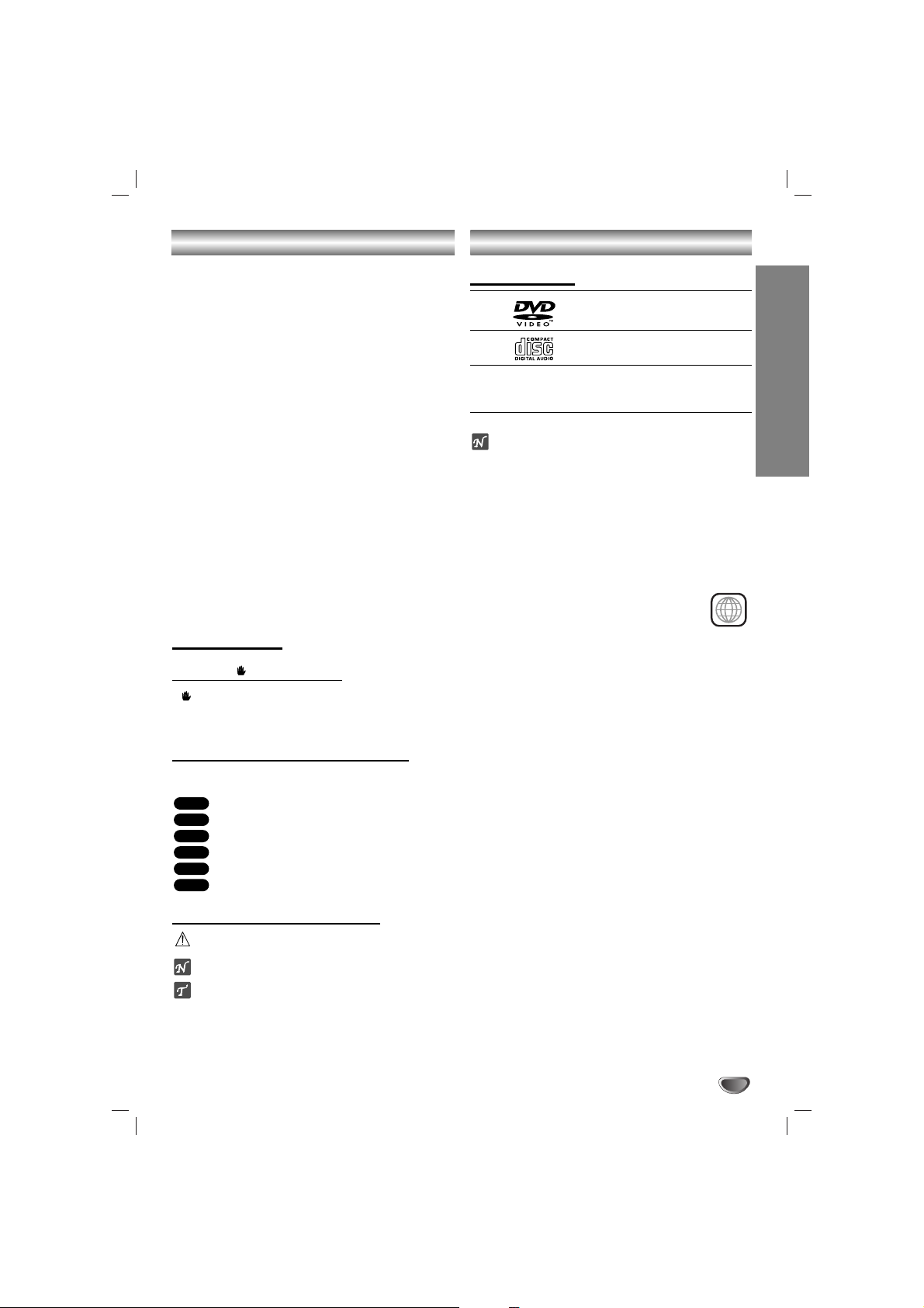
Front Panel/ Rear Panel
1. NUMERIC buttons (0~9)
2. DISPLAY WINDOW
3. POWER ( STANDBY/ON) button
4. • PROGRAM/MEMORY (PROG./MEMO.) button
• STEREO/MONO (ST./MO.),
HIGH DUBBING (HI-DUBB.) button
• CD SYNCHRO RECORDING (CD SYNC.),
NORMAL DUBBING (NOR-DUBB.) button
• RECORD/RECORD PAUSE (zREC/[]) button
5. HEADPHONE SOCKET (PHONES): 3.5 mm
6. USB connector
7. • FUNCTION SELECT buttons
(TUNER, KARAOKE DVD/CD, TAPE, USB, AUX)
• SET/CD[], RDS (OPTIONAL) button
• XDSS plus button
• XTS Pro button
• Virtual E.X button
• EQ master button
• VOLUME knob
8. Z PUSH EJECT position (TAPE 1)
9. Z PUSH EJECT position (TAPE 2)
10 • PRESET (-/+) buttons
• TAPE REVERSE PLAY (bb) button
• PLAY (BB) button
• STOP (xSTOP) button
• CD SKIP/SEARCH (.
bbbb/BBBB
>), TAPE
REWIND/ FAST FORWARD (.
bbbb/BBBB
>),
TUNING (-/+) buttons
11.• MIC VOLUME KNOB (MIC VOL.)
• MIC JACKS (MIC1, MIC2): 6.3 mm : OPTIONAL
12. • DISC SKIP (D.SKIP) button
• CLOCK button
• TIMER button
• PLAY MODE, DEMO button
13. • OPEN/CLOSE (ZOP./CL.) button
•
DISC
SELECT
buttons (DISC1, DISC2, DISC3)
14. DISC
DOOR
15. • EURO AV TO TV connector
• VIDEO OUT SELECTOR switch
16. •
COMPONENT VIDEO OUT (PROGRESSIVE SCAN)
(Y Pb Pr) Connector
• VIDEO OUT Connector
17. LM-KW3960Q model
• WIRELESS MIC CHANNEL SWITCH
•
WIRELESS MIC ANTENNA Connector
18. • FM/AM ANTENNA Connector
• AUXILIARY INPUT (AUX IN) connector
19. POWER CORD
20.
SPEAKER Connectors
21. S-VIDEO OUT Connector
(LM-K3960Q/LM-KW3960Q/
LM-K3860Q/LM-K3565Q model)
1
3
4
5
6
7
8
9
10
11
12
13
2
19
17
16
20
21
14
15
18
LM-K3960Q/LM-KW3960Q/
LM-K3860Q/LM-K3565Q model
LM-KW3960Q
model
COMPONENT
(PROGRESSIVE SCAN)
Pr
Y
VIDEO OUT
Pb
EURO AV
TO TV
S-VIDEO
OUT
AUX IN
C
H
A
N
N
E
L
MIC ANT.
FRONT
R (4 )
FRONT
L (4 )
5
INTRODUCTION
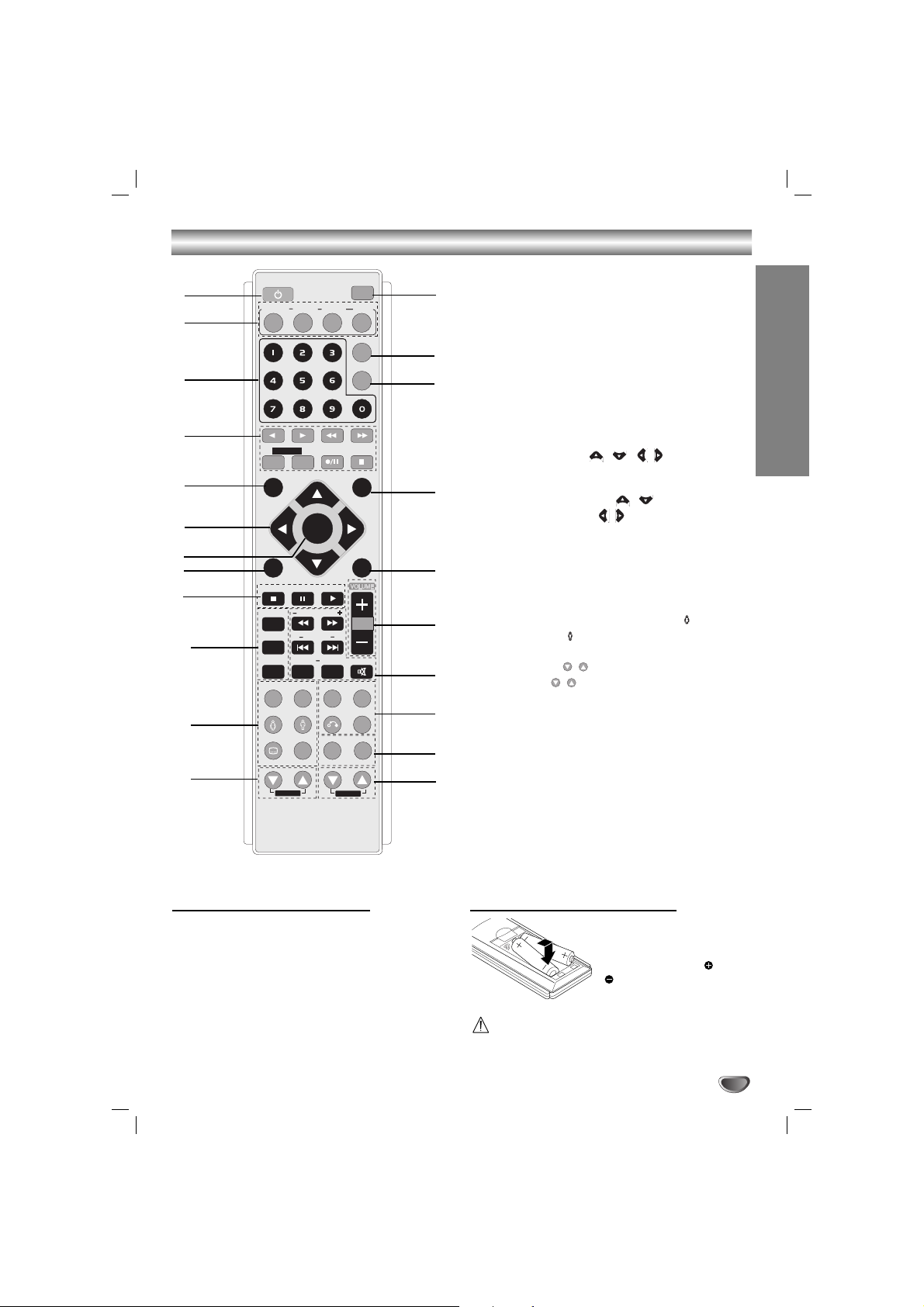
Remote Control
Remote Control Operation Range
Point the remote control at the remote sensor and press
the buttons.
• Distance: About 23 ft (7 m) from the front of the
remote sensor
• Angle: About 30° in each direction of the front of the
remote sensor
Remote control battery installation
Detach the battery cover on
the rear of the remote control, and insert two R03 (size
AAA) batteries with and
aligned correctly.
Caution
Do not mix old and new batteries. Never mix different
types of batteries (standard, alkaline, etc.).
1. POWER button
2. FUNCTION SELECT buttons
(TUNER/BAND, DVD/KARAOKE, AUX, USB)
3. NUMERIC buttons (0-9)
4. TAPE FUNCTION buttons
- REVERSE PLAY (
F
)
- PLAY (
G
)
- REWIND/ FAST FORWARD PLAY (
FF/GG
)
- TAPE 1-2 SELECT buttons (1-TAPE-2)
- RECORD/ RECORD PAUSE (z/[])
- TAPE STOP (x)
5. SET UP button
6. • ARROW buttons ( / //)
(For use in highlighting a selection on a GUI
menu screen, TITLE and MENU screen.)
• PRESET (-/+) buttons ( / )
• TUN. (-/+) buttons ( / )
7. SELECT/ENTER button
8. MENU button
(Use the MENU button to display the menu screen
included on DVD video discs.)
9. STOP (x), PAUSE([])/ STEP, PLAY (
G
) buttons
10. PROG./MEMO., REPEAT, REPEAT A-B buttons
11.
EQ master, XTS Pro, SOUND/FEMALE( ),
AUDIO/MALE( ), SUBTITLE (S-TITLE)/SHADOW,
CLEAR buttons
12. ECHO VOL. ( / ) buttons
13. MIC VOL. ( / ) buttons
14. RDS, PTY buttons (OPTIONAL)
15.
XDSS plus, VIRTUAL E.X,
RETURN, ZOOM buttons
16. SCAN (
FF/GG
)/ TEMPO (-/+)/ KEY CONTROL
(b/#)/ SKIP (./>), MARKER, SEARCH,
MUTE buttons
17. VOLUME -/+ buttons
18. TITLE button
(Use the TITLE button to display the title screen
included on DVD video discs.)
19. DISPLAY button
20. DIMMER button
21. SLEEP button
22. DISC SKIP (D.SKIP) button
POWER
1
6
5
4
3
2
8
9
7
10
12
11
21
20
18
16
17
19
13
15
22
14
TUNER/BAND
DVD/
KARAOKE
D.SKIP
AUX
USB
SLEEP
1 - TAPE - 2
SETUP
PRESET +
TUN. - TUN. +
MENU
STOP PLAY
PAUS E/STEP
PROG./MEMO.
REPEAT
b
REPEAT A-B
MARKER SEARCH
XTS Pro
EQ master
SOUND AUDIO
S-TITLE
CLEAR
SHADOW
ECHO VOL.
SELECT
/ENTER
PRESET -
TEMPO
KEY CON
#
XDSS plus
RETURN
RDS PTY
MIC VOL.
VIRTUAL E.X
DIMMER
DISPLAY
TITLE
MUTE
ZOOM
Connections
6
• Make one of the following connections, depending on
the capabilities of your existing equipment.
ips
• Depending on your TV and other equipment you wish
to connect, there are various ways you could connect
the
unit
. Use one of the connections described below.
• Please refer to the manuals of your TV, VCR, Stereo
System or other devices as necessary to make the
best connections.
Caution
–
Make sure the unit is connected directly to the TV.
Select the correct AV input on your TV.
– Do not connect your
unit
to TV via your VCR. The
DVD image could be distorted by the copy protection
system.
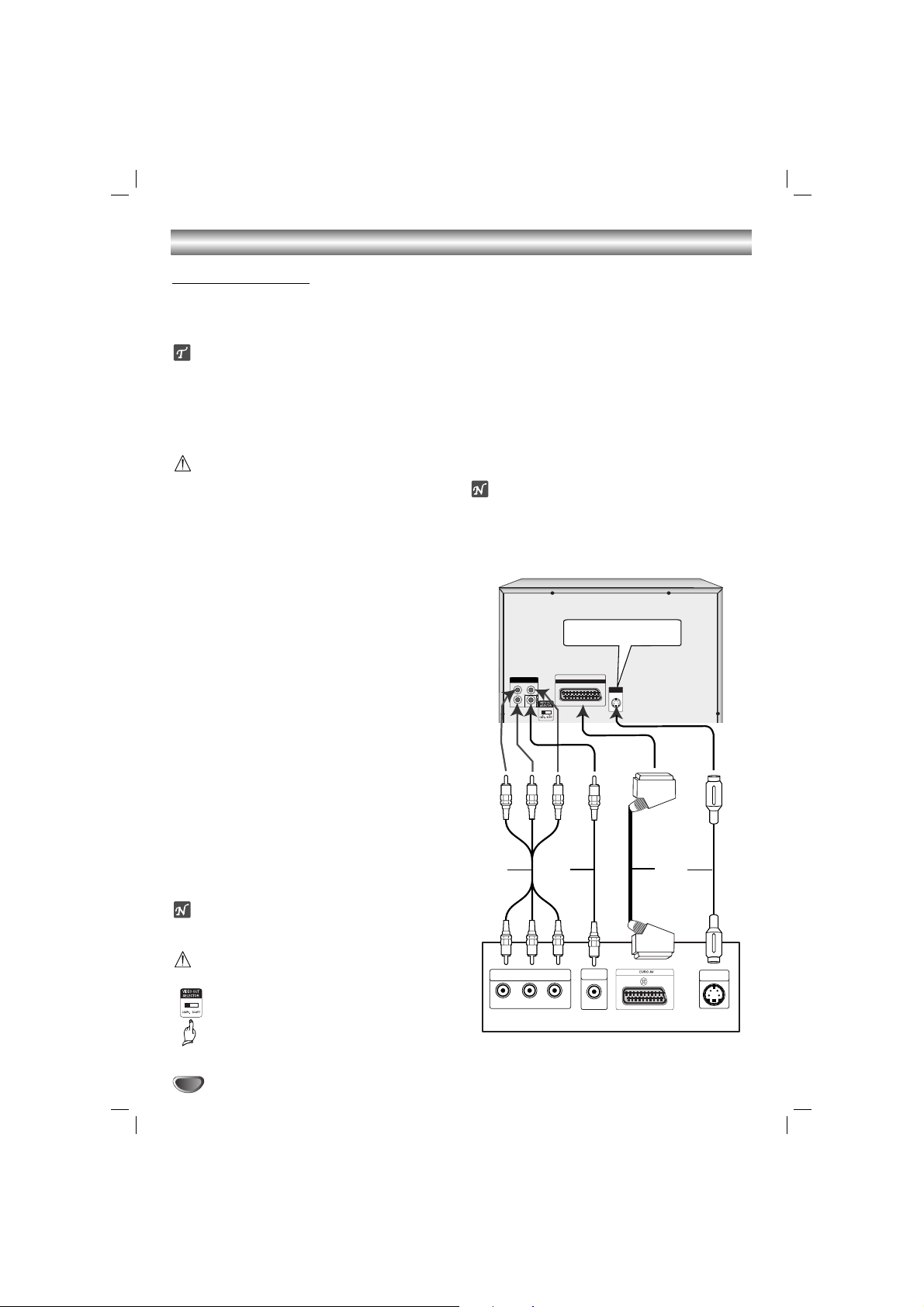
Video connection
Connect the VIDEO OUT jack from the
unit
to the
VIDEO IN jack on the TV using the video cable supplied
(V).
S-Video connection (
LM-K3960Q/LM-KW3960Q/
LM-K3860Q/LM-K3565Q model)
Connect the S-VIDEO OUT jack on the
unit
to the S-
VIDEO IN jack on the TV using the S-Video cable (S).
Component Video (Color Stream®) connection
Connect the COMPONENT VIDEO OUT (PROGRESSIVE SCAN) (Y Pb Pr) jacks from the
unit
to the corre-
sponding in jacks on the TV using an Y Pb Pr cable (C).
SCART connection
11
Connect the EURO AV TO TV connector on the unit
to the corresponding in jacks on the TV by using
the scart cable (T).
22
In order to receive the TV audio signal press the
AUX button on the front panel or the remote control
until the “TV-AUDIO” indicator is displayed in the
display window.
ote
A picture via scart input is not supported.
Caution
VIDEO OUT SELECTOR switch
In power-off status, select either COMPONENT VIDEO OUT (PROGRESSIVE SCAN)
or SCART signal of EURO AV TO TV terminal
depending on how to connect the unit to the
TV.
Progressive Scan (ColorStream®pro) connection
• If your television is a high-definition or “digital ready”
television, you may take advantage of this
unit
’s
progressive scan output for higher video resolution.
•If your TV does not accept the Progressive Scan format, the picture will appear scrambled if you try
Progressive Scan on the
unit
.
Connect the COMPONENT VIDEO OUT (PROGRESSIVE SCAN) (Y Pb Pr) jacks from the
unit
to the corre-
sponding in jacks on the TV using an optional Y Pb Pr
cable (C).
otes
– Set the Progressive to “On” in the Setup menu for
progressive signal, see page 15.
– Progressive Scan can not be selected in the setup
menu when the VIDEO OUT SELECTOR switch is set
at SCART position.
Connecting to a TV
LM-K3960Q/LM-KW3960Q/
LM-K3860Q/LM-K3565Q model
COMPONENT
VIDEO OUT
(PROGRESSIVE SCAN)
Pb
Pr
Y
C
H
A
N
N
E
L
MIC ANT.
C
EURO AV
TO TV
WOOFER
PRE-OUT
AUX IN
V
S-VIDEO
OUT
REAR
REAR
CENTER
WOOFER
R (8 )
L (8 )
(8 )
(3 )
FRONT
FRONT
R (4 )
L (4 )
S
T
COMPONENT VIDEO /
PROGRESSIVE SCAN INPUT
Pr
Pb
Y
VIDEO
IN
L
Rear of TV
S-VIDEO
IN
7
Connections
PREPARATION
COMPONENT
Pr
Pb
Y
VIDEO OUT
S-VIDEO
OUT
OPTICAL
IN
EURO AV
TO TV
MIC ANT.
C
H
A
N
N
E
L
FRONT
R (4 )
FRONT
L (4 )
AUX IN
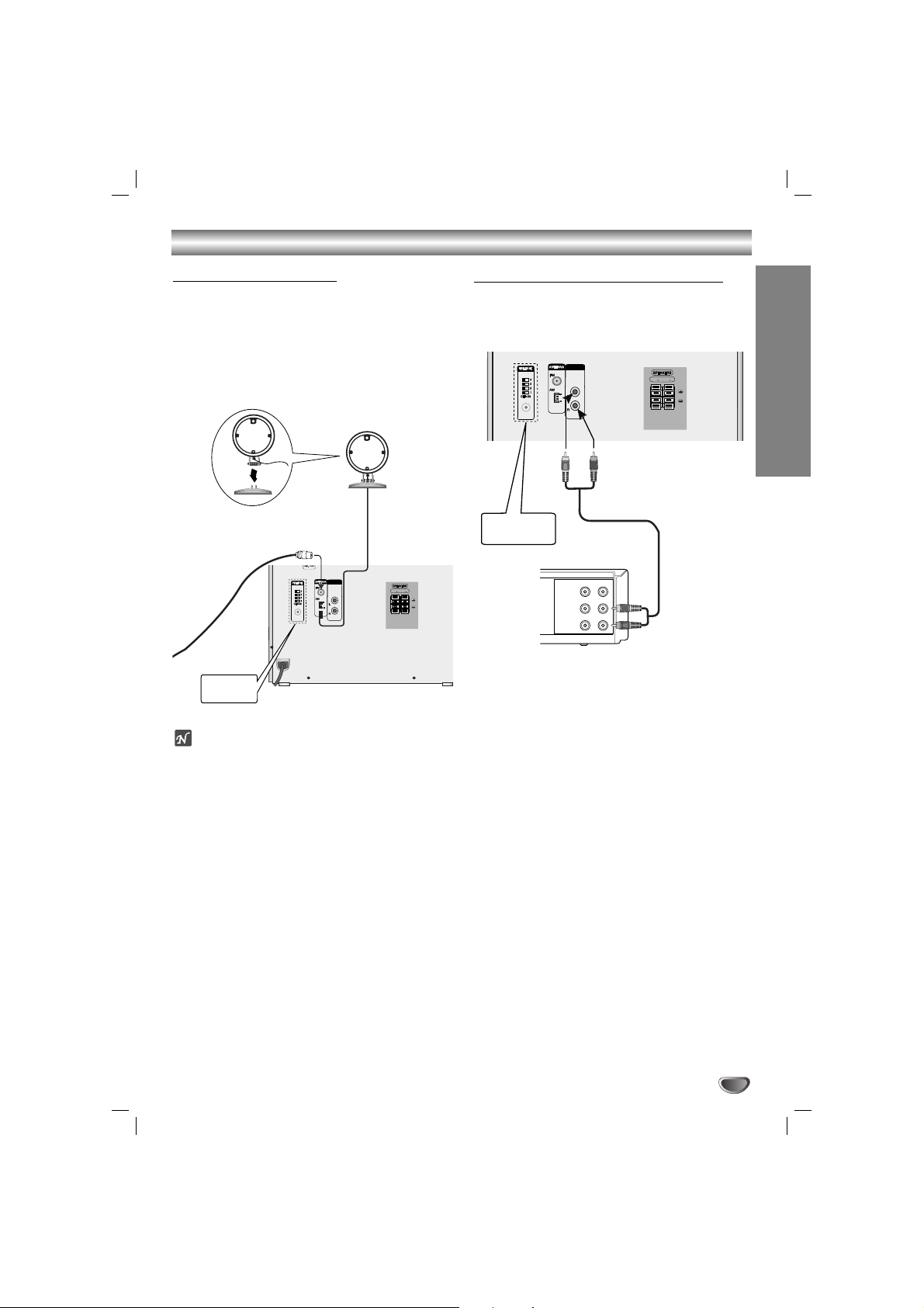
Connecting to Antenna
Connect the supplied FM/AM antennas for listening to
the radio.
- Connect the AM loop antenna to the AM antenna
connector.
- Connect the FM wire antenna to the FM antenna
connector.
otes
•To prevent noise pickup, keep the AM loop antenna
away from the unit and other component.
• Be sure to fully extend the FM wire antenna.
• After connecting the FM wire antenna, keep it as horizontal as possible.
Connecting to Auxiliary Equipment
You can use VCR or other unit connected to the AUX
connector.
This unit receives the analog signal from auxiliary
equipment.
MIC ANT.
C
H
A
N
N
E
L
VIDEO
OUTIN
AUDIO (L)
AUDIO (R)
FRONT
R (4 )
FRONT
L (4 )
AUX IN
11
Connect a VCR or auxiliary device, etc to the
AUX connector.
22
Press the AUX button on the front panel or the
remote control until the “AUX” indicator is
displayed in the display window.
AM(MW) loop
antenna (aerial)
(Supplied)
For AM(MW) reception, connect
the loop antenna (aerial) to the terminal marked AM
FM wire
antenna
(supplied)
LM-KW3960Q
model
VCR (or Auxiliary Device, etc)
To AUDIO IN
To AUDIO OUT
LM-KW3960Q
model
Connections
8
Connecting to the Wireless microphone
anten
na - LM-KW3960Q model
When you use the wireless microphone, connect the
supplied wireless microphone antenna to the wireless
microphone antenna jack of the unit.
MIC ANT.
C
H
A
N
N
E
L
FRONT
R (4 )
FRONT
L (4 )
AUX IN
Wireless microphone
antenna
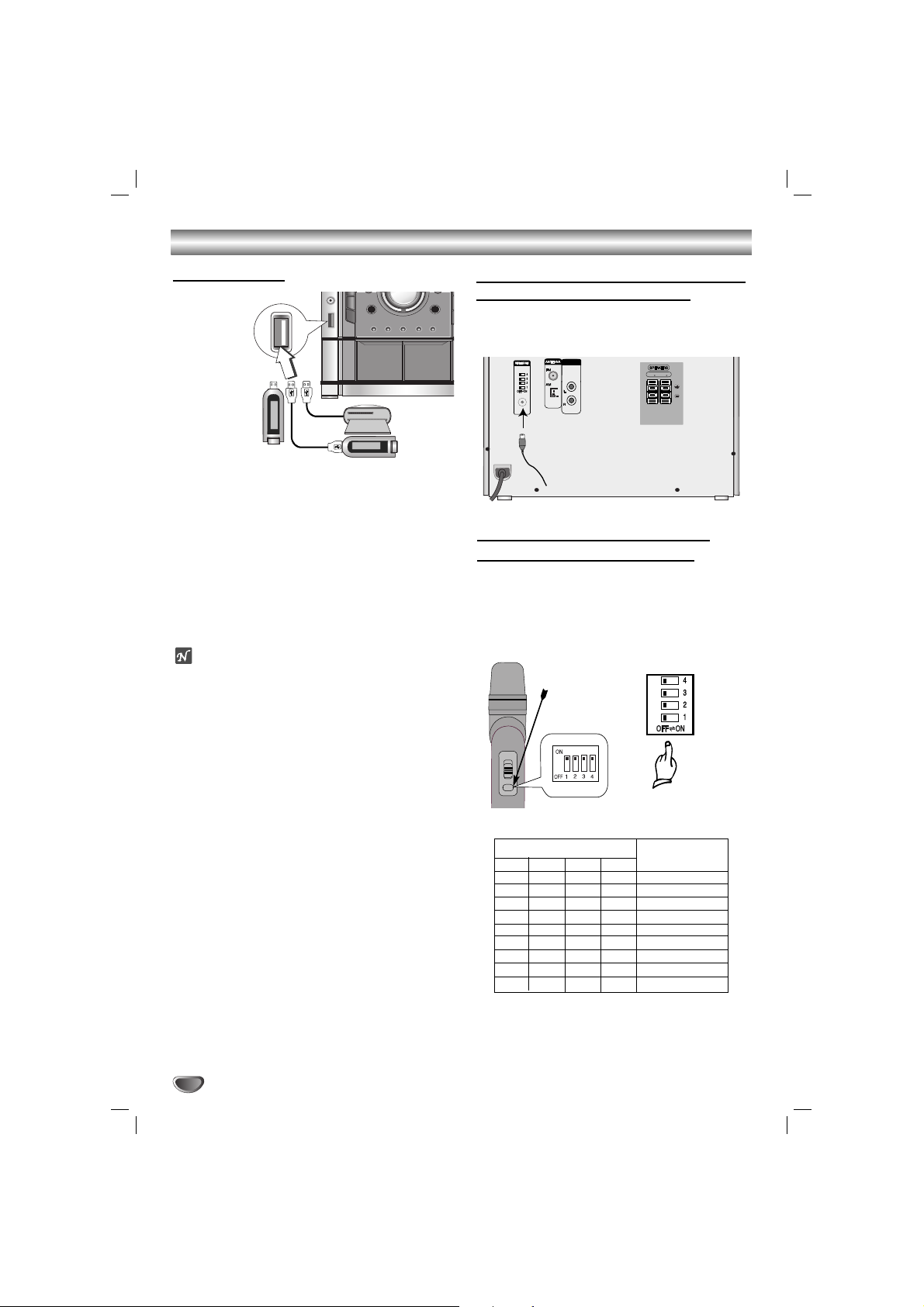
Setting the Wireless microphone
Channel - LM-KW3960Q model
• If there is a similar wireless microphone product
nearby, interference may occur. In this case, change
the channel switch to other channel, and turn off the
power, then turn on again.
By using the Channel Switch, set the same channel.
•You can set the channel change with 9 types.
C
H
A
N
N
E
L
[Rear panel of the unit]
ON
[Wireless microphone]
Open the cover.
1
ON
OFF
ON
OFF
ON
OFF
ON
OFF
ON
2
OFF
ON
ON
OFF
OFF
ON
ON
OFF
OFF
3
OFF
OFF
OFF
ON
ON
ON
ON
OFF
OFF
4
OFF
OFF
OFF
OFF
OFF
OFF
OFF
ON
ON
CH1
CH2
CH3
CH4
CH5
CH6
CH7
CH8
CH9
Channel switch number
Channel number
Connecting USB
11
Connect the USB port of USB memory (or MP3
player, etc) to the USB connector on the front
panel.
22
Select USB function by pressing the USB
button on the front panel or the remote control.
The “USB” is displayed in the display window.
To Remove the USB from the unit
1. Choose a different function mode or press the STOP
(x) twice in a row.
2. Remove the USB from the unit.
otes
• Don’t extract the USB device in operating.
• Music files (MP3/WMA), image files (JPEG) and DivX
files can be played.
• This unit can not use USB HUB.
• Recommended Memory Card
Compact Flash Card (CFC), Micro Drive (MD), Smart
Media Card (SMC), Memory Stick (MS), Secure Digital
Card (SD), Multi Media Card (MMC), Memory Stick Pro
(MS-Pro)
- Compatable with : FAT16,32
- Only use the memory cards recommended.
• Devices which require additional program installation
when you have connected the unit to a computer are
not supported.
•
In case of a USB HDD, make sure to connect an auxiliary power cord to the USB HDD for porper operation.
A primary partition of drive is supported up to four. If
there is an extention partition it is not supported.
• If the drive of USB device is two or more, a drive
folder is displayed on the screen. If you want to move
to the previous menu after you select a folder, Press
RETURN.
• Digital camera and mobile phone are not supported.
USB Memory,
MP3 Player (or
Memory Card
Reader, etc.)
Connections
PREPARATION
9
Pr
Pb
Y
S-VIDEO
OUT
EURO AV
TO TV
MIC ANT.
C
H
A
N
N
E
L
FRONT
R (4 )
FRONT
L (4 )
AUX IN
COMPONENT
(PROGRESSIVE SCAN)
VIDEO OUT
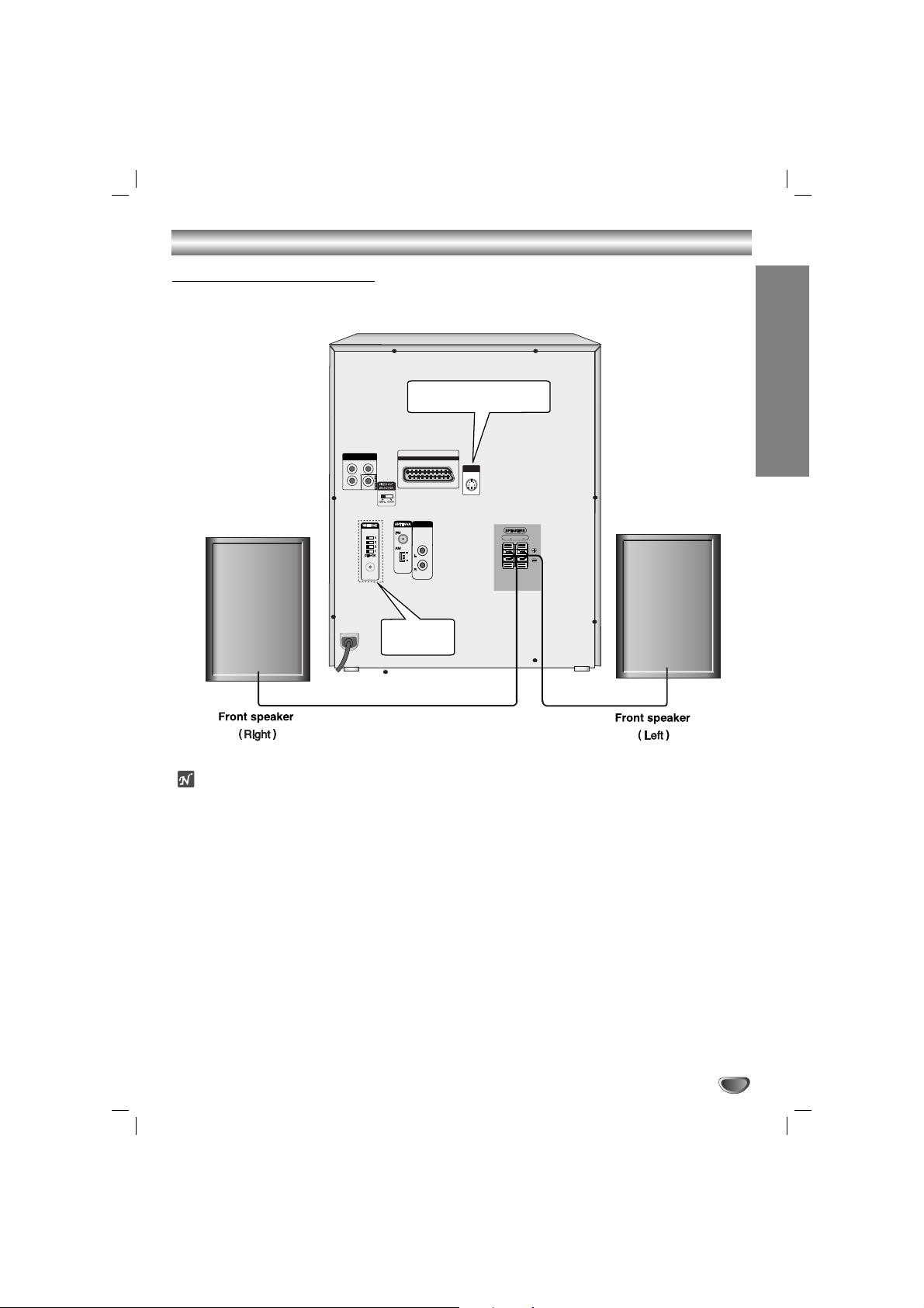
otes
• Be sure to match the speaker cable to the appropriate terminal on the components: + to + and – to –. If the
cables are reversed, the sound will be distorted and will lack base.
• If you use front speakers with low maximum input rating, adjust the volume carefully to avoid excessive output on
the speakers.
• Connect the Front Left/Right speaker correctly. If it is reversed, the sound may be distorted.
Speaker System Connection
Connect the speakers using the supplied speaker cables by matching the colors of the terminals and those of the
cords.
LM-K3960Q/LM-KW3960Q/
LM-K3860Q/LM-K3565Q model
LM-KW3960Q
model
Before Operation
10
Volume Adjustment
•Turn VOLUME knob clockwise to increase the sound
level, or counterclockwise to decrease it.
• Press VOLUME + to increase the sound level, or use
VOLUME - to decrease it on the remote control.
MUTE
Press MUTE to turn off the sound, press again to
restore.
“” indicator flashes in the display window.
Headphone Jack
Connect a stereo headphone plug ( 3.5mm) into the
headphone jack.
The speakers are automatically disabled when you plug
in headphones (not supplied).
EQUALIZER Effect
You can choose 7 fixed sound impressions and adjust
the BASS, MIDDLE and TREBLE.
-You can select a desired sound mode by using EQ
master button on the front panel or the remote
control.
When you want to change a sound mode press the
EQ master button repeatedly within 3 seconds.
Each time you press the button the setting changes in
the display window as shown below.
NORMAL → USER EQ → POP → CLASSIC
↑
JAZZ ← DRAMA ← ROCK
-You can set the BASS, MIDDLE and TREBLE on the
USER EQ mode.
1.Select the USER EQ mode by using EQ master
button.
“USER EQ” will be displayed in the display window.
2.Press the SET/CD[[button on the front panel when
“USER EQ” is displayed in the display window.
“BASS 0” will be displayed in the display window.
3.Select the BASS, MIDDLE or TREBLE you want by
pressing the PRESET (-/+) buttons on the front
panel.
4.Press the TUNING (-/+) buttons on the front panel
to set the sound level you want. (MIN, -4 ~ +4,
MAX steps)
5.Repeat the 3-4 steps as above.
6.When the sound level is completed, press the the
SET/CD[[button on the front panel.
DEMO
Press DEMO in power off state to demonstrate the
function in the display window.
To cancel, press POWER ( STANDBY/ON) or DEMO
again.
XDSS (Extreme Dynamic Sound System)
You can improve the sound quality during playback.
Press XDSS plus repeatedly on the remote contol.
NORMAL y XDSS ON
NORMAL → XDSS ON → MP3 - OPT ON
XTS pro
Each time you press XTS pro the setting changes in
the following order.
NORMAL y XTS-P ON
• XTS-P ON
The unique sound quality of the LG Technology creates the optimum sound for you to play the perfect
playback of the original sound and to feel the living
sound source.
otes
This function does not work when the microphone is in use.
VIRTUAL sound
Press
VIRTUAL E.X
the setting virtual sound.
• 3D STEREO
Realtime 3D positioned sound rendering technology
with stereo sources, optimized for stereo speakers.
Listeners may experience amazing virtual surround
effects with their own multimedia players.
•Virtual sound
A pending downmix technology converts 5.1 channel
to 2 channel sound having directional information of
audio. And it makes a 2 channel or 2.1 channel feel
5.1 channel sound.
DIMMER
This function dims the LED (Light-emitting diode) of
front panel by half in power-on status.
Press DIMMER once. The LED (Light-emitting diode) of
front panel is turned off and the display window will be
darken by half. To cancel, press the button again.
Source Display Effect
2.1 ch. VIRTUAL 3D STEREO
5.1 ch VIRTUAL Virtual sound
MP3/WMA
DVD/DivX/CD
PREPARATION
11
Before Operation
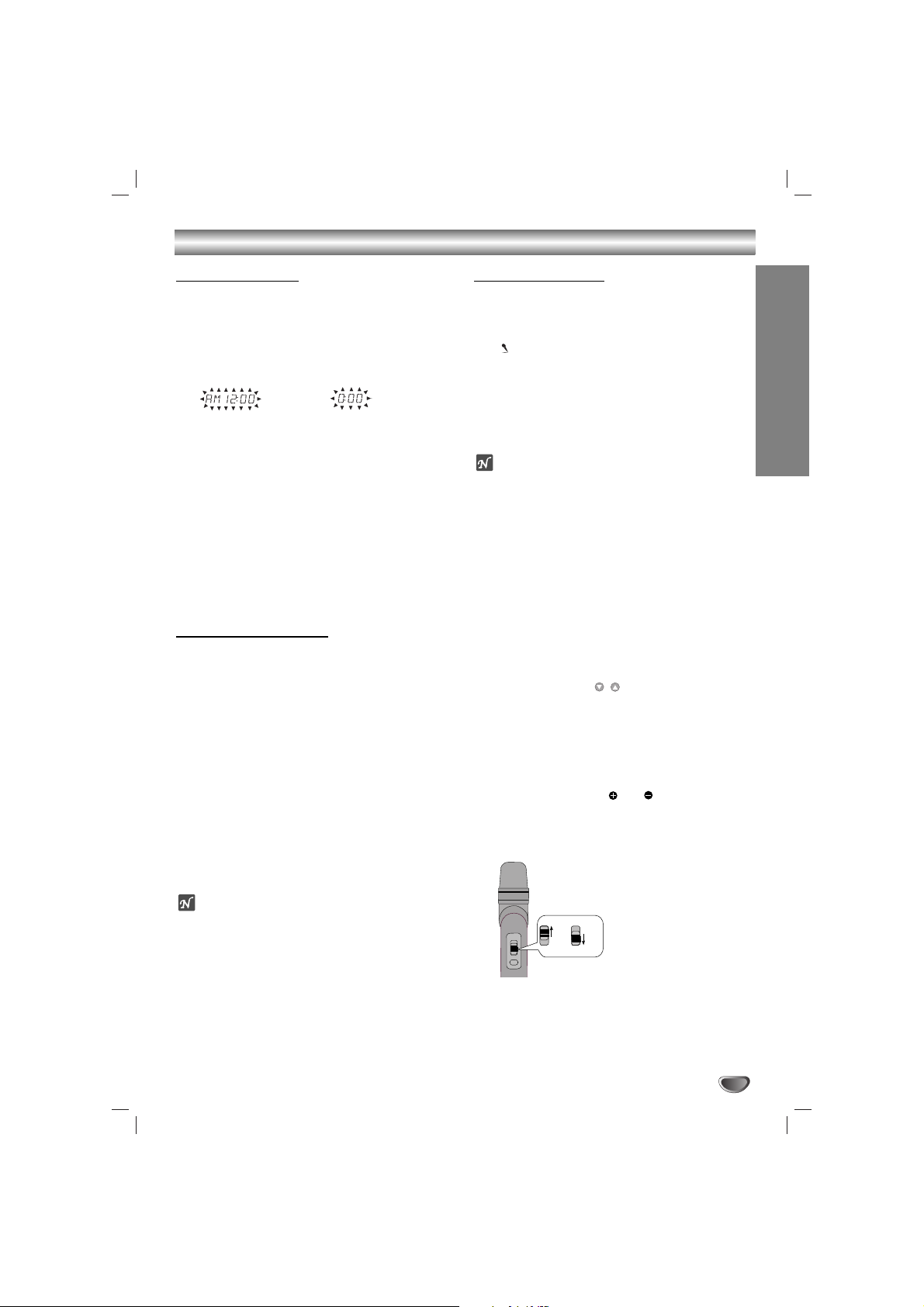
Setting the Clock
11
Press CLOCK.
(If the clock requires setting, press and hold CLOCK
for more than 2 seconds.)
- The hours display begins to blink.
22
Select a 24 hour cycle or 12 hour cycle by
pressing
.. bbbb/BBBB >>
on the front panel.
33
Press SET/CD[[to confirm the selected hour
cycle.
44
Use
.. bbbb/BBBB >>
on the front panel to set
the correct hours.
55
Press SET/CD[[.
66
. Use
.. bbbb/BBBB >>
on the front panel to set
the correct minutes.
77
Press SET/CD[[and the correct time is shown in
the display window.
Sleep Timer Function
When the sleep timer is set, the unit automatically turns
off after the specified time has elapsed.
11
To specify the time delay before the power is
turned off, press SLEEP.
In the display window you can see SLEEP 180 for
about 5 seconds. This means that the system turns
off automatically after 180 minutes.
22
Each time you press SLEEP the setting changes
in the following order.
SLEEP 180 →150 → 120 →90→80→70 → 60→ 50 →
40 → 30 → 20 →10 → OFF (No display) →SLEEP 180...
33
To check the remaining time until the power is
turned off.
While the sleep function is active press SLEEP
briefly. The time remaining until the unit turns off is
displayed for about 5 seconds.
ote
If you press SLEEP while the sleep time is displayed,
the SLEEP time is reset.
To cancel Sleep Timer setting
If you wish to stop the function, press the SLEEP button
repeatedly until “SLEEP 10 ” appears, and then press
SLEEP once again after “SLEEP 10 ” shows on the
display.
Using Microphone
You can sing to a music source by connecting a
microphone to the unit.
11
Connect your microphone to the MIC socket.
“” will be shown in the display window.
22
Play the music you want.
33
Sing along with the accompaniment.
Adjust the microphone volume by turning MIC
VOLUME KNOB. (MIN,1 - 14, MAX steps)
otes
• When not using the microphone, set the MIC volume
knob to minimum or turn off the MIC and remove the
microphone from the MIC socket.
• If the microphone is set too near the speaker, a
howling sound may be produced. In this case, move
the microphone away from the speaker or decrease
the sound level by using the MIC volume control.
• If sound through the microphone is extremely loud, it
may be distorted. In this case, turn the MIC volume
control toward minimum.
To Adjust ECHO Volume
You can give an echo effect to the sound from the
microphones.
Press the ECHO VOL. ( / ) on the remote control to
increase the echo volume or decrease it. (MIN,1 - 14,
MAX steps)
(12HR)
(24HR)
or
Using the wireless microphone - LM-KW3960Q
model only
Before you use the wireless microphone, detach the cover
on the rear of the wireless microphone and insert three
R06 (size AA) batteries with and aligned correctly.
11
Connect the supplied wireless microphone
antenna. (Page 8)
22
Turn the wireless microphone on.
33
Set the wireless microphone channel. (Page 8)
ON
OFF
ON
ON
ON
OFF
OFF
 Loading...