

Page 1

© Copyright 2008, LG Electronics U.S.A., Inc.
Zenith and the lightning Z logo are registered
trademarks of Zenith Electronics Corporation
Free-To-Guest (FTG) Configuration Application
Configuration Software For Pro:Idiom Enabling Devices
TV/FTG card/Computer Setup
Page 2
2
WARNING:
TO REDUCE THE RISK OF ELECTRIC SHOCK DO NOT REMOVE COVER (OR BACK). NO USER SERVICEABLE
PARTS INSIDE. REFER TO QUALIFIED SERVICE PERSONNEL.
The lightning flash with arrowhead symbol, within an equilateral triangle, is intended to alert the user to the
presence of uninsulated “dangerous voltage” within the product’s enclosure that may be of sufficient magnitude to constitute a risk of electric shock to persons.
The exclamation point within an equilateral triangle is intended to alert the user to the presence of important
operating and maintenance (servicing) instructions in the literature accompanying the appliance.
WARNING:
TO PREVENT FIRE OR SHOCK HAZARDS, DO NOT EXPOSE THIS PRODUCT TO RAIN OR MOISTURE.
NOTE TO CABLE/TV/STB INSTALLER:
This reminder is provided to call the cable TV/STB system installer’s attention to Article 820-40 of the National
Electric Code (U.S.A.). The code provides guidelines for proper grounding and, in particular, specifies that the
cable ground shall be connected to the grounding system of the building, as close to the point of the cable
entry as practical.
REGULATORY INFORMATION:
This equipment has been tested and found to comply with the limits for a Class B digital device, pursuant to
Part 15 of the FCC Rules. These limits are designed to provide reasonable protection against harmful interference when the equipment is operated in a residential installation. This equipment generates, uses and can
radiate radio frequency energy and, if not installed and used in accordance with the instruction manual, may
cause harmful interference to radio communications. However, there is no guarantee that interference will not
occur in a particular installation. If this equipment does cause harmful interference to radio or television
reception, which can be determined by turning the equipment off and on, the user is encouraged to try to correct the interference by one or more of the following measures:
• Reorient or relocate the receiving antenna.
• Increase the separation between the equipment and receiver.
• Connect the equipment into an outlet on a circuit different from that to which the receiver is connected.
• Consult the dealer or an experienced TV/STB technician for help.
CAUTION:
Do not attempt to modify this product in any way (except as noted herein) without written authorization from
LG Electronics U.S.A., Inc. Unauthorized modification could void the user’s authority to operate this product.
COMPLIANCE:
The responsible party for this product’s compliance is:
LG Electronics U.S.A., Inc., 2000 Millbrook Drive
Lincolnshire, IL 60069, USA • Phone: 1-847-941-8000.
WARNING
RISK OF ELECTRIC SHOCK
DO NOT OPEN
Marketed and Distributed in the United States by LG Electronics U.S.A., Inc.
2000 Millbrook Drive, Lincolnshire, IL 60069
206-4081
Page 3

3
Follow the instructions below to set up an LG/Zenith TV/STB for Pro:Idiom standalone operation.
(FTG Card requires LG/Zenith TV/STB with MPI card slot)
1. Set up commercial features of TV/STB. Enter Installer Menu and set all desired items as required. (i.e. Tuning
Band, Start Channel etc.) Refer to the Installation and Setup Guide of the TV/STB.
2. Load the FTG Configuration Application program onto the PC that will be used to configure the FTG card.
3. Install FTG card into TV/STB’s MPI card slot and connect PC. (See page 19)
4. Execute the FTG Configuration Application and create a configuration file.
5. Build a Channel Map and ‘Write’ it to FTG card.
6. If necessary, make changes to Installer Menu items using FTG Installer Menu Configuration utility and ‘Write’
them to FTG card.
7. Save the configuration file (*.rml) for future use.
8. Tune TV/STB to a Logical Channel in the Channel Map.
206-4081
Free-To-Guest (FTG) Quick Setup Guide
Table Of Contents
Refer to the pages listed below for specific topic details.
Quick Setup Guide . . . . . . . . . . . . . . . 3
FTG Configuration Application Installation 4
FTG Configuration Application Setup . . . 5
The Configuration File . . . . . . . . . . . . . 6
Channel Map Editor . . . . . . . . . . . . . . 7
Channel Map Write / Read Functions . . . 8
Channel Map Learn Function . . . . . . . . . 9
Installer Menu Configuration . . . . . . . . 10
Installer Menu Access Is On . . . . . . . . 11
Installer Menu Read / Write Functions . 12
Installer Menu Configuration Learn Func. 13
Save Configuration File . . . . . . . . . . . 14
Set TV/STB Clock . . . . . . . . . . . . . . . 15
System Requirements/Operational Tips . 16
HCS1410 FTG Card Overview . . . . . . . . 17
HCS1410 FTG Card Data Flow . . . . . . . . 18
HCS1410 FTG Card Installation . . . . . . 19
HCS1410 FTG Card Features . . . . . . . . . 20
Reference
Changeable Installer Menu Items 21-22-23
Incompatible Installer Menu Items . . . . 24
Troubleshooting . . . . . . . . . . . . . . . . 25
Frequently Asked Questions (FAQs) 26-27
Warranty . . . . . . . . . . . . . . . Back Cover
Install FTG Card
Follow installation procedures on page 19.
Note: Design and specifications are subject to change without prior notice.
Page 4
4
FTG Configuration Application Installation
Installing the Application
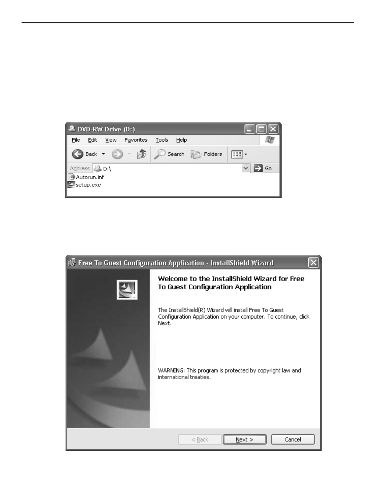
Install FTG Configuration Application Program from CD, or download from www.lgcommercial.com/hospitality.
If Autorun from install disk does not start, explore the disk and double click on setup.exe file.
InstallShield Wizard
Complete installation using InstallShield Wizard.
Page 5
5
On the PC
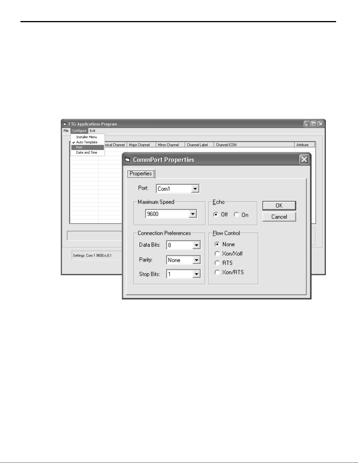
Com Port Properties
Port: Com1 (Set to available communication port)
Maximum Speed: 9600 (Required Setting)
Echo: Off (Required Setting)
Data Bits: 8 (Required Setting)
Parity: None (Required Setting)
Stop Bits: 1 (Required Setting)
Flow Control: None (Required Setting)
FTG Configuration Application Setup
Setting Up the Application and Communication
Connect a F-F null MODEM cable between the PC RS-232 port and the FTG card RS-232 port.
Execute FTG Configuration Application. (Double click on FTG Configuration Shortcut on Desktop.)
Configure port communications. Click ‘Configure’, then ‘Port’.
Page 6
6
The Configuration File
Using the FTG Configuration Application
The FTG Configuration Application is used to create a Configuration File (*.rml) that contains the data to be
transferred and stored in a FTG card. A configuration file consists of both a Channel Map and an Installer Menu
Configuration. Using the FTG Configuration Application, the Channel Map can be created, however the Installer
Menu Configuration data must be transferred to the application from an installed FTG card before changes may be
made. Therefore, a FTG Channel Map may be developed, saved offsite and then sent to the location of the
TV/STB installation. Both the Channel Map and the Installer Menu Configuration data are read, edited and then
written separately to a FTG card. The configuration file should be saved to be used at a later time if changes
become necessary or to configure additional FTG cards.
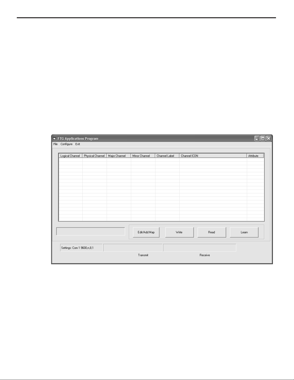
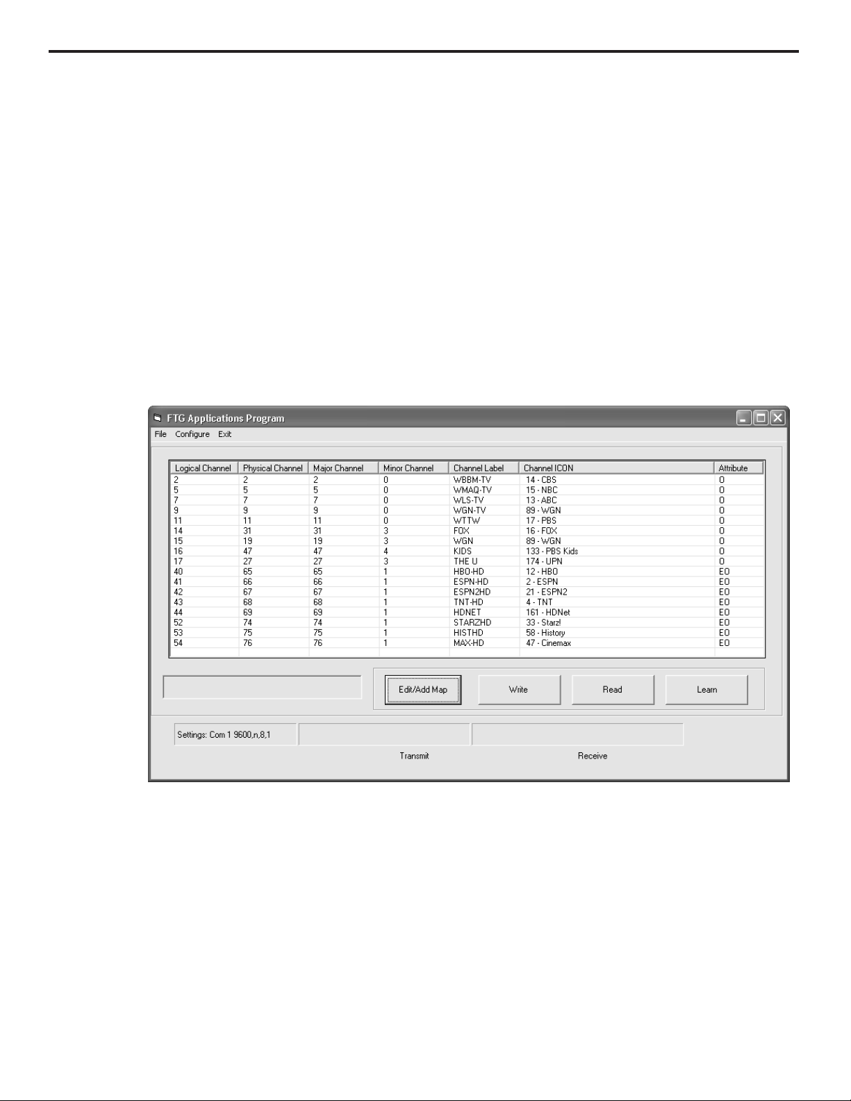
FTG Configuration Application
Channel Map Functions
Edit/Add Map – Opens the Channel Map Editor to create or edit a Channel Map.
Write – The FTG Channel Map is transferred to the FTG card and the TV/STB.
Read – The FTG Channel Map is transferred from the FTG card to the application.
Learn – The TV/STB Channel Map is “learned” from the TV/STB and transferred to the FTG card and application.
Page 7
Using the FTG Configuration Application
The FTG Channel Map data stored in a FTG card provides the TV/STB with a list of channels available to tune. The FTG
Channel Map also allows an easy method for adding a label and/or icon to be displayed when a channel is tuned. If channels
with Pro:Idiom encrypted content are part of the channel lineup, define the channel(s) and set the ‘Encrypted’ Attribute to
enable an LG/Zenith Pro:Idiom TV/STB to decrypt the content. A FTG Channel Map can be created or edited by clicking the
‘Edit/Add Map’ button.
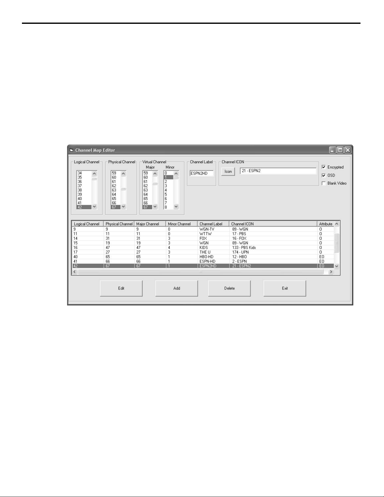
Channel Map Editor
Item Range Description
Logical Channel 0 - 1000 Channels tuned by user, defined by system operator
Physical Channel* 1 - 137 RF channels designated at headend
Major Channel 1 - 255 Same as Physical Channel unless: Installer Menu item 103 is set to ’0’ (zero) virtual
Minor Channel 0 - 255 ‘0’ if channel is an analog source. 1 - 255 if the channel is a digital source
*Physical Channel number 254 tells the system to tune the Aux set by Installer Menu item ‘46 Start Aux Source’.
Create a Channel Map
A FTG Channel Map may include up to 141 channel entries (Logical Channels). Choose a Logical Channel number from
0 to 1000 and define the channel by setting its Physical and Virtual Channel Numbers. A Channel Label may be entered
and/or Channel Icon selected. The Channel Label allows up to 7 characters to be entered. To select a Channel Icon, click the
‘Icon’ button, the icons are listed alphabetically. The channel Attributes may also need to be set. Select ‘Encrypted’ if
Pro:Idiom encrypted content will be provided on that channel. Select ‘OSD’ to display the channel’s Logical Channel number
as well as any Channel Label and/or Channel Icon, entered. Select ‘Blank Video’ when defining audio only channels to display a blank screen. Once a channel has been defined, click the ‘Add’ button and it will appear in the bottom panel of the
Channel Map Editor. Continue adding channels to build the FTG Channel Map.
Edit a Channel Map
To edit a channel, click on the channel in the bottom panel. Its defining elements will be shown above, ready for editing.
Make any and all changes then click the ‘Edit’ button to save the changes and update its bottom panel listing. If it is necessary to remove a channel, click on the channel in the bottom panel then click the ‘Delete’ button. When Channel Map editing is complete, click the ‘Exit’ button to close the Editor window and return to the main application window.
Channel Map Editor
7
Page 8
Channel Map Write / Read Function
Using the FTG Configuration Application
Once created, a Channel Map, can be written to and read from an FTG card with the FTG Configuration
Application. A FTG card must be installed in a TV/STB and a PC with the FTG Configuration Application connected to the FTG card as outlined in the Setup. A Channel Map must be stored in a FTG card to provide the TV/STB
with a list of channels to tune. If a FTG card has a Channel Map it can be transferred to the FTG Configuration
Application and saved in a configuration file. A Channel Map that has been saved can be used at a later time.
See The Configuration File. The configuration file may be opened for reference or for editing purposes. If
changes are made to the Channel Map it may be saved again as the same name, replacing the existing file, or
saved as a new name preserving the previous file. Also, if additional FTG cards are to be configured at a later
time, a saved configuration file may be opened and used.
FTG Configuration Application
Write a Channel Map
To transfer a Channel Map to a FTG card, click the ‘Write’ button on the main application window. The FTG
Channel Map is transferred from the PC to the FTG card and stored in both the FTG card and TV/STB. The Logical
Channels will be tuned exactly as they appear in the FTG Channel Map.
Read a Channel Map
To transfer a Channel Map from a FTG card, click the ‘Read’ button on the main application window. The FTG
Channel Map stored in the FTG card is transferred from the FTG card to the PC. The FTG Channel Map will appear
exactly as it did when it was originally stored in the FTG card. To transfer a TV/STB Channel Map to a FTG card
and the FTG Configuration Application see Learn a Channel Map.
Save a Channel Map
To save a Channel Map, click ‘File’, then ‘Save’. The Save As window will appear, the FTG Channel Map will be
saved in a configuration file (*.rml). Name the file and click the ‘Save’ button.
See also Save Configuration File
8
Page 9
9
Channel Map Learn Function
Using the FTG Configuration Application
Although it is not recommended, it may be necessary to perform a channel search on the TV/STB to determine
the channels available on the RF feed. Also, Aux input labeling may be changed. Refer to the Installation and
Setup Guide of the TV/STB for complete instructions. Even though it is recommended that this procedure be performed prior to installing the FTG card, it is possible for it to be performed after FTG card installation, see
Installer Menu Access Is On.
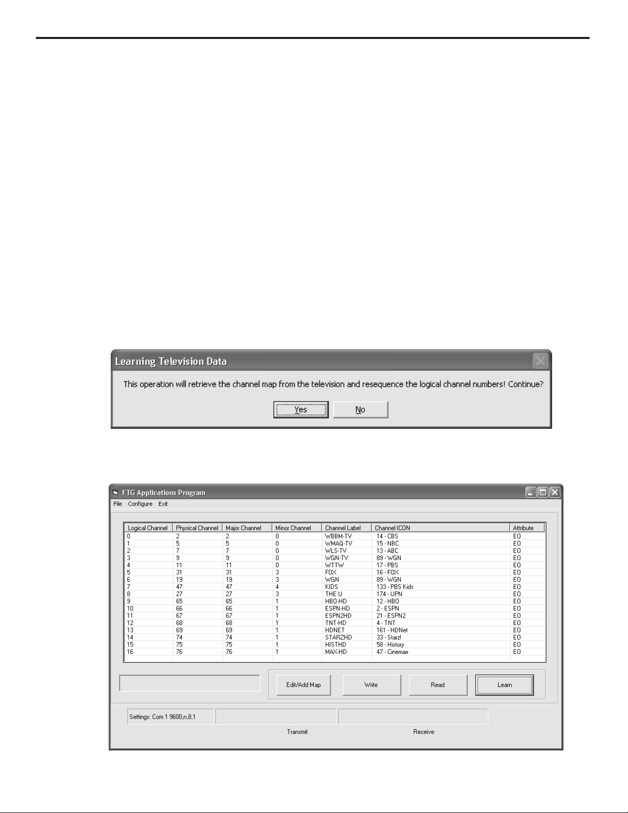
Learn a Channel Map
If it is necessary to transfer a TV/STB Channel Map to the PC, click the ‘Learn’ button. Logical Channel numbers
will automatically be assigned in ascending order, starting with 0 (zero), to the Physical Channels from the
TV/STB Channel Map. All the channels will have ‘Encrypted’ and ‘OSD’ Attributes set. During the transfer, the
FTG card’s channel map is also updated. If the FTG card and TV/STB were storing a FTG Channel Map from a previous ‘Write’ that map’s Logical Channels will be reassigned in ascending order starting with 0 (zero). This
Channel Map may be edited by opening the Editor, see Channel Map Editor.
Learn Function Caution
Learned Channel Map
(Logical Channels reassigned)
Page 10

10
Installer Menu Configuration
Using the FTG Configuration Application
The Installer Menu is used to configure the commercial features of the TV/STB. Example Installer Menu Items are
Tuning Band, Tuning Mode, Start Channel, Aux source enable/disable, etc. See Index tab of FTG Installer Menu
Configuration utility for entire list. To use the FTG Installer Menu Configuration utility click ‘Configure’, then
‘Installer Menu’.
Note: Detailed descriptions of Installer Menu items are provided in the TV/STB manual.
The Installer Menu Configuration utility allows access to changeable Installer Menu items
(see table on pages 21 - 23).
Installer Menu Configuration Functions
Installer Menu Access is (Off/On) – Allows access to TV/STB Installer Menu with IR remote.
Write – The FTG Installer Menu Configuration is transferred to the FTG card and the TV/STB.
Read – The FTG Installer Menu Configuration is transferred from the FTG card to the application.
Learn – The TV/STB Installer Menu is "learned" from the TV/STB and transferred to the FTG card and application.
Exit – Closes Installer Menu Configuration utility and returns to the main application window.
Page 11

11
Installer Menu Access Is On
Using the FTG Configuration Application
The Installer Menu Configuration utility is used to make changes to the Installer Menu settings of the TV/STB.
An Installer Menu Configuration can not be created using the FTG Configuration Application it must first be
transferred from an installed FTG card to the Installer Menu Configuration utility. This ensures that only the
Installer Menu items appropriate for the model in which the FTG card is installed are available to change.
Installer Menu items that are not changeable are shown in gray and can not be accessed.
Installer Menu Configuration
(Prior to transfer from FTG card)
Installer Menu Access Is On
In normal operation, with FTG card installed, access to the TV/STB main menu is not allowed (‘Installer Menu
Access Is Off’). Click ‘Installer Menu Access Is Off’ button and the button text will change to ‘Installer Menu
Access Is On’. The ‘Installer Menu Access Is On’ function allows the TV/STB main menu to be accessed with a
IR remote which then allows the TV/STB Installer Menu to be accessed while the FTG card is installed. While in
this mode the FTG Configuration Application will not function.
The Installer Menu Access must be turned Off to return functionality to the FTG Configuration Application. Click
‘Installer Menu Access Is On’ button and the button text will change to ‘Installer Menu Access Is Off’. Any
changes made to the TV/STB Installer Menu by an IR remote will not be retained if AC power is cycled unless
transferred to the FTG card. See Learn an Installer Menu Configuration.
Page 12

12
Installer Menu Read / Write Functions
Using the FTG Configuration Application
Upon installation of a factory fresh FTG card in a TV/STB, the FTG card acquires the Installer Menu settings that
were established in that TV/STB prior to card installation. See FTG card Data Flow figures on page 18. The
Installer Menu Configuration utility should be used to make changes to Installer Menu settings after the FTG card
is installed. To edit Installer Menu items the Installer Menu must first be transferred from the FTG card to the
PC. All Installer Menu item changes must be transferred back to FTG card and TV/STB before the changes will
take affect.
Installer Menu Configuration
(After transfer from FTG card)
Read an Installer Menu Configuration
To transfer an Installer Menu Configuration from a FTG card, click the ‘Read’ button in the Installer Menu
Configuration utility. The Installer Menu settings stored in the FTG card are transferred from the FTG card to the
PC. The appropriate Installer Menu settings will now be available for editing and/or saving to a configuration
file. To transfer a TV/STB Installer Menu to a FTG card and the FTG Configuration Application see Learn an
Installer Menu Configuration.
Write an Installer Menu Configuration
To transfer an Installer Menu Configuration to a FTG card, click the ‘Write’ button in the Installer Menu
Configuration utility. The FTG Installer Menu Configuration is transferred from the PC to the FTG card and stored
in both the FTG card and TV/STB.
Exit the Installer Menu Configuration Utility
To exit the Installer Menu Configuration utility, click the ‘Exit’ button in the Installer Menu Configuration utility.
Exit – Closes Installer Menu Configuration utility and returns the main application window.
Page 13

13
Installer Menu Configuration Learn Function
Using the FTG Configuration Application
The Installer Menu Configuration utility ‘Learn’ function allows changes that are made to the TV/STB Installer
Menu by an IR remote to be transferred to the FTG card and the Installer Menu Configuration utility. Only certain
circumstances require this action. One would be, if it is necessary to reset Installer Menu settings to the Factory
Defaults using an IR remote. Refer to the Installation and Setup Guide of the TV/STB for complete instructions.
The aforementioned operation is made possible by the following actions:
A) While the FTG card is installed set ‘Installer Menu Access Is On’. See ‘Installer Menu Access Is On’.
Or
B) Remove FTG card, complete the procedure, and re-install FTG.
The Installer Menu settings must be transferred to FTG card before the changes will take affect. To do this, the
TV/STB Installer Menu items must be "learned" by the FTG card and the Installer Menu Configuration utility.
Learn an Installer Menu Configuration
If it is necessary to transfer a TV/STB Installer Menu to the FTG card and the Installer Menu Configuration utility,
click the ‘Learn’ button. The TV/STB Installer Menu data is stored in the FTG card and transferred to the
Installer Menu Configuration utility. The appropriate Installer Menu settings will now be available for editing
and/or saving to a configuration file. If addition changes are made, the Installer Menu Configuration must be
transferred back to the FTG card. See Write an Installer Menu Configuration.
Learn Function Caution
During the transfer, the FTG card’s channel map is also updated. If the FTG card and TV/STB were storing a FTG
Channel Map from a previous Channel Map ‘Write’ that map’s Logical Channels will be reassigned in ascending
order starting with 0 (zero). All the channels will have ‘Encrypted’ and ‘OSD’ Attributes set. This new Channel
Map may be transferred to the PC and edited. See the Channel Map Write / Read Functions and Channel Map
Editor.
Save an Installer Menu Configuration
To save an Installer Menu Configuration, ‘Exit’ the Installer Menu Configuration. On the main application window
click ‘File’, then ‘Save’. The Save As window will appear, the Installer Menu Configuration will be saved in a
configuration file (*.rml). Name the file and click the ‘Save’ button.
See also Save Configuration File
Page 14

14
Save Configuration File
Using the FTG Configuration Application
A configuration file consists of both a Channel Map and an Installer Menu. The configuration file should be
saved to be used at a later time. If changes are made to the Channel Map and/or the Installer Menu
Configuration the configuration file may be saved again as the same name, replacing the existing file, or saved
as a new name preserving the previous file.
Save a configuration file
To save a configuration file, click ‘File’, then ‘Save’. The Save As window will appear. The configuration file will
be given the extension (*.rml). Name the file and click the ‘Save’ button.
Page 15

15
Using the FTG Configuration Application
The clock of the TV/STB may be set using the FTG Configuration Application. The TV/STB will be set to the same
date and time as the PC. Be sure that the PC has the correct date and time. To disable user access to the
TV/STB Clock settings, this operation must be the final FTG Configuration Application operation performed.
Set the Clock
To set the TV/STB clock, click ‘Configure’, then ‘Date and Time’.
Set TV/STB Clock
Page 16

16
System Requirements / Operation
FTG Configuration Application
• PC System running Windows XP operating system or later
• Minimum of 16 MB of RAM
• Minimum of 15 MB free HDD space for FTG Configuration Application.
Additional space required for channel database(s)
• 800 x 600 SVGA display
• RS-232 serial port set to 9600 baud, 8 data bits, no parity, 1 stop bit
FTG Card
• LG/Zenith Pro:Idiom TV/STB with MPI card slot
• PTC Version V_XX_XX_XXX or later, refer to Compatibility list on page 17
System Operation
The LG/Zenith Free-To-Guest card solution for Pro:Idiom standalone operation. When an LG/Zenith Pro:Idiom
TV/STB is tuned to a channel that has Pro:Idiom encrypted content and that channel is defined in the FTG
Channel Map with the ‘Encrypted’ Attribute set, the FTG card enables the TV/STB to decrypt the content.
System Planning and Tips
• Before setting up the system, a Channel Mapping Plan and a Master TV/STB Setup should be devised.
• It is recommended that the channel map include Logical Channels in sequential order 0-1-2-3 etc., but is
not required when defined using the FTG Configuration Application.
• The plan should have a layout that determines whether Physical or Virtual channel numbers will be used
and the sequence that the channels will appear on the TV/STB.
• It is necessary to know the Physical or Virtual channel number of each channel to be included in the FTG
Channel Map. If Digital channels are to be included both the major and the minor channel numbers are
required. For analog channels the Minor channel number is always 0 (zero).
• When the TV/STB Installer Menu item 103 ATSC Mode is set to physical (1) the Physical Channel number
and the (Virtual) Major Channel number are the same.
Page 17

17
HCS1410 Free To Guest (FTG) Card Overview
Purpose
• To provide commercial TV/STB’s with a way to map
Logical channel numbers to Physical or Virtual
channels.
• To provide the forensic marking for Pro:Idiom
encrypted programs. This enables Pro:Idiom
decryption in the TV/STB.
• To provide an easy means to set the date and time
of the TV/STB.
The goal is to set up a TV/STB with the desired
Installer Menu settings before inserting a blank
HCS1410. When the blank card is inserted, the
Installer Menu settings are copied into the card. The
HCS1410 can then be configured with the desired
FTG Channel Map. If multiple TV/STBs of the same
model are to be configured with FTG Cards, this configured card may be removed and inserted into an
identical TV/STB, which will then be ready for operation.
Compatibility
The HCS1410 is compatible with the following
products:
• 20LH1DC1/26LH1DC1/32LH1DC1
• 26LH1DC3/26LH1DC4
• 32LC5DC/37LC5DC/42LC5DC
• 32LX5DC
• 42PX7DC
• 42PX8DC
• HCS5610
• HCS5650
• L20V54S
• L26W56
• L26W58
• LST4100A (V1.06.000 or greater only)
• LST4600A (V1.01.000 or greater only)
• LST4600W
• LST6600A
The LST5600A PTC V1.00.001 needs to be upgraded
to a later version to be fully compatible.
For products that were not listed, the Configuration
Application will only be able to make changes to a
limited number of Installer Menu items. It is recommended that Installer Menu items be set on the
TV/STB using the IR remote control. These products
will, however, be able to accept the channel map and
the date and time from the Configuration
Application.
Specifications
• 141 Channel entries.
• Maximum Logical Channel Number = 4095*
*Software limits this to 1000 to enhance
performance
HCS1410 FTG Card Limitations
The HCS1410 does not take the place of a clone box
where the setup learned from a master TV/STB can
be replicated into other TV/STBs. The HCS1410, however, can replicate some items but not all.
Items That Can Be Replicated
• Installer Menu settings initially learned when a
factory-fresh card is inserted into a TV/STB.
• Installer Menu settings that were written by the
FTG Configuration Application.
• Channel lineup written by the FTG Configuration
Application.
• Aux labels if initially learned from the TV/STB that
has been set up with the labels. (Aux labels are
not transferred between the PC and the FTG card,
therefore they cannot be saved in the configuration file.)
Items That Cannot Be Replicated (Refer to TV/STB
Manual)
• Settings from the TV/STB’s Main Menu.
Page 18

18
Figure 1. Data Flow – Between FTG Card and Target TV/STB
Condition of HCS1410: Factory-fresh or previously used in a
different model TV/STB.
* If channel map is blank, no transfer will occur.
Figure 2. Data Flow – Between FTG Card and Target TV/STB
Condition of HCS1410: Previously used in a TV/STB of the same
model.
The HCS1410 FTG card must be installed in the MPI
card slot of the target TV/STB.
Defaults As Shipped
The HCS1410 is shipped with no mapped channels
and with no default Installer Menu. When the card is
inserted into a TV/STB, the current Installer Menu
settings of the TV/STB are replicated into the
HCS1410. See Figure 1. From then on, Installer Menu
items on the card can only be changed by using the
FTG Configuration Application.
Installing in Same Model
By setting the TV/STB with the desired Installer
Menu settings before inserting a factory-fresh
HCS1410, once inserted, this card can now be used
to set the Installer Menu items of other TV/STBs of
the same model. See Figure 2.
Installing in Different Model
An HCS1410 that was previously used on a different
model TV/STB will not carry over the Installer Menu
settings of the previous product into the target
TV/STB. Rather, it will load the settings of the target
TV/STB into the HCS1410. See Figure 1.
Configure HCS1410
As mentioned, the HCS1410 as shipped has no channels mapped. Assuming that the current Installer
Menu settings allow channel changes, numeric
entries are interpreted as direct tune to channels.
However, decryption of encrypted channels is not
possible at this time. The HCS1410 must be configured first.
Refer to the Free to Guest Configuration Application
and this manual to configure card.
HCS1410 FTG Card Data Flow
FTG CARD
INSTALLER
MENU
CHANNEL
MAP*
TARGET TV/STB
INSTALLER
MENU
CHANNEL
MAP
FTG CARD
INSTALLER
MENU
CHANNEL
MAP MAP
TAR GET TV/STB
INSTALLER
MENU
CHANNEL
Page 19

19
HCS1410 FTG Card Installation
RS-232 PORT (Male)
Connect RS-232 Null Modem cable
here from a PC to configure the
FTG card.
ANTENNA/CABLE INPUT
Receives RF signals
.
REMOVAL HOOK
After removing retaining
screws, pull firmly on
hook to remove card.
RETAINING SCREW
Install after inserting
the FTG card.
RETAINING SCREW
Install after inserting
the FTG card.
Caution: Disconnect power cord from unit
before attempting to remove MPI card.
1. Remove both retaining screws and partially pull
out current card from MPI slot so that the RF
cable can be disconnected.
2. Disconnect RF cable and totally pull out the
current card.
3. Partially slide the HCS1410 into the MPI slot.
4. Connect RF cable.
5. Fully slide the HCS1410 in so that the card seats
securely into the backplane connector
6. Install retaining screws.
7. Wait at least 40 seconds after AC power is applied
to the system before turning the unit on.
8. The HCS1410 “Banner” will appear momentarily
on the TV screen, the first time the system is
turned on after AC power is applied, displaying
the firmware version.
RF CABLE
RF cable needs to be connected when HCS1410 is
installed
.
The HCS1410 FTG card must be installed in the target TV/STB with an MPI card slot. Data identifying the target TV/STB is read by the FTG card when the system powers up. If the card has never been used before, or if
it was used in a different model product, the card’s Installer Menu settings will be initialized with the current settings of the target TV/STB. This will prevent FTG cards that were set using a different model product
from incorrectly configuring the target TV/STB. Only the Installer Menu settings are re-initialized. Refer to
HCS1410 Changeable Installer Menu Settings, Table 1.
The channel map on the FTG card, which can only be changed through the FTG Configuration Application,
will remain intact.
UPDATE BUTTON
Press to allow firmware to be
updated. After card is installed, to
start download program, press and
hold while AC power is applied to
unit. During normal operation,
press and hold to display firmware
version / serial number and the
number of mapped channels
.
R
S
2
3
2
ANTENNA
/CABLE
R
S
2
3
2
ANTENNA
/CABLE
HCS1410
M.P. I.
DC IN
M.P. I.
Card Slot
HCS1410
M.P. I.
Page 20

20
Direct Access Tuning
Once the Channel Map has been stored, the channels
can be accessed using their Logical channel numbers.
This can be done by entering the channel number
followed by the “ENTER/OK”. If the channel number
is not followed by “ENTER/OK”, the channel will
change 2 seconds after the last digit was pressed. If
the number of digits entered is the same as the
number of digits of the highest Logical channel, the
channel change will initiate immediately. Channel
numbers may be preceded by zero(s) and will be
counted as a digit pressed.
Limited Menu
After the HCS1410 is installed, a limited menu is
available to the user. To prevent inadvertent changes
to Video and Audio Settings, access to these and
other menu items are disabled.
Firmware Version
The HCS1410 “Banner” will appear momentarily
on the TV screen, the first time the system is
turned on after AC power is applied, displaying
the firmware version.
The firmware version is also displayed anytime the
Update Button is pressed on the front of the card.
This “Banner” additionally shows the card serial
number and the number of mapped channels.
HCS1410 Installer Menu Defaults
The Installer Menu settings listed below are required
for proper FTG card operation and are set by the FTG
card. Any changes made will be overwritten when the
FTG card is installed. Once the FTG card is installed,
the following Installer Menu item settings must not
be changed.
HCS1410 LED Indicators
The LED, visible through the opening behind the
removal hook, will glow RED when it is first powered
up and will remain lit until the card has finished initializing.
• The LED will glow GREEN if there is activity
to/from the PC.
• The LED will glow RED if there is activity to/from
the TV/STB.
Item Installer Menu Descriptions Preset
00 INSTALLER_SEQ 00
29 OLD_OCV 00
30 ACK_MASK 00
31 POLL_RATE 94
32 TIMING_PULSE 207
47 AUX_STATUS 01
53 DIS_CH_TIME 01
69 EN_CH_T_COL 01
70 FOR_CH_TIME 02
71 BCK_CH_TIME 02
82 CHKSUM_ERROR 01
83 HANDSHK_TIME 05
102 ATSC_BAND 04
HCS1410 FTG Card Features
Page 21

21
The table shows which menu items are changeable for the different TV/STB models
Reference: Changeable Installer Menu Items
Item Menu Item LST4600A LST4100A LST5600A 42PX7DC
0
INSTALLER SEQ Preset to default 0
1
POWER MANAGE Y Y Y Y Y Y Y Y Y Y
2
3
4
5
6
7
8
9
10
11
12
13
14
15
16
17
18
19
20
21
22
23
24
25
26
27
28
29
30
31
32
33
34
35
36
37
38
39
40
41
42
43
44
45
46
47
48
49
50
51
52
AC ON Y Y Y Y Y Y Y Y Y Y
BAND/AFC Y Y Y Y Y Y Y Y Y Y
STRT CHANNEL Y Y Y Y Y Y Y Y Y Y
CHAN LOCK Y Y Y Y Y Y Y Y Y Y
GHOST CH. NOT USED
STRT VOLUME Y Y Y Y Y Y Y Y Y Y
MIN VOLUME Y Y Y Y Y Y Y Y Y Y
MAX VOLUME Y Y Y Y Y Y Y Y Y Y
MUTE DISABLE Y Y Y Y Y Y Y Y Y Y
KEY DEFEAT N Y N Y Y Y Y N N Y
IR BANKS EN. N N N N N Y Y N Y N
SCAN MODE N N N N N Y Y N Y N
STRT CH IN SM N N N N N Y Y N Y N
SLEEP TIMER Y Y Y Y Y Y Y Y Y Y
EN. TIMER Y Y Y Y Y Y Y Y Y Y
ALARM Y Y Y Y Y Y Y Y Y Y
RADIO EN. NOT USED
UNASSIGNED NOT USED
FEATURE LEVEL Y N Y N N Y Y N Y N
V-CHIP Y Y Y Y Y Y Y Y Y Y
MAX BLK HRS Y Y Y Y Y Y Y Y Y Y
CAPTION LOCK Y Y Y Y Y Y Y Y Y Y
TEXT MODE NOT USED
FUNCTION PRE N N N N N Y Y N Y N
6 KEY SYS NOT USED
HOSPITAL MODE N N N N N Y Y N Y N
CH. OVERIDE Y Y Y Y Y Y Y Y Y Y
OLD OCV Preset to default 0
ACK MASK Preset to default 0
POLL RATE Preset to default 94
TIMING PULSE Preset to default 207
Y/C LOOP OUT NOT USED
CAMPORT EN. N Y N Y Y Y N Y Y Y
COMPPORT EN. Y Y Y Y Y Y Y Y Y Y
FRNT Y/C EN. N N N N N N N Y Y N
REAR Y/C EN. Y N Y N N N N N N N
Y Y Y Y Y Y N Y Y Y YPrPb EN.
REAR AUX EN. Y Y Y Y Y Y Y Y Y Y
AUTO CAMPORT N Y N Y Y Y N N N Y
AUTO COMPPORT NOT USED
AUTO FRNT Y/C NOT USED
AUTO REAR Y/C NOT USED
AUTO YPrPb NOT USED
AUTO REAR AUX NOT USED
STRT AUX SRCE Y Y Y Y Y Y Y Y Y Y
AUX STATUS Preset to 1
DIS. SETUP M. NOT USED
DIS. AUDIO M. NOT USED
DIS. VIDEO M. NOT USED
DIS. PTL. M. NOT USED
DIS. SOURCE M NOT USED
L26W56S
26LH1DC3
26LH1DC4
L26W58H
26LH1DC1
32LH1DC1
L20V54S
HCS5610 HCS5650 LC5, LX5
20LH1DC
PX8, LB5
Page 22

22
Reference: Changeable Installer Menu Items
The table shows which menu items are changeable for the different TV/STB models
Item Menu Item LST4600A LST4100A LST5600A 42PX7DC
53
54
55
56
57
58
59
60
61
62
63
64
65
66
67
68
69
70
71
72
73
74
75
76
77
78
79
80
81
82
83
84
85
86
87
88
89
90
91
92
93
94
95
96
97
98
99
DIS. CH-TIME Preset to 1
EN. SETUP COL. NOT USED
FOR. SETUP M. NOT USED
BCK. SETUP M. NOT USED
EN. AUDIO COL. NOT USED
FOR. AUDIO M. NOT USED
BCK. AUDIO M. NOT USED
EN. VIDEO COL. NOT USED
FOR. VIDEO M. NOT USED
BCK. VIDEO M. NOT USED
EN. PTL. COL. NOT USED
FOR. PTL. M. NOT USED
BCK. PTL. M. NOT USED
EN. SRC. COL. NOT USED
FOR. SRC. M. NOT USED
BCK. SRC. M. NOT USED
EN. CH-T COL. Preset to default 1
FOR. CH-TIME Preset to default 2
BCK. CH-TIME Preset to default 2
NTSC SCANCARD NOT USED
CH NOT AVBLE N Y N Y Y Y Y Y Y Y
CH-TIME SIZE NOT USED
REVERT CH N Y N Y Y Y Y Y Y Y
DEFEAT XDS NOT USED
QUICK SHUTOFF N N N N N Y Y N Y N
UPN MSB LEAVE ALONE
UPN MSB-1 LEAVE ALONE
UPN MSB-2 LEAVE ALONE
UPN LSB LEAVE ALONE
CHKSUM ERROR Preset to default 1
HANDSHK TIME Preset to default 5
PERMANENT BLK Y Y Y Y Y Y Y Y Y Y
A. MUTE TIME NOT USED
V. MUTE TIME NOT USED
REAR RGB EN. Y Y Y Y Y Y N Y Y Y
EN NOISE MUTE N Y N Y Y Y Y Y Y Y
POKE_ENABLE NOT USED
KEY LOCK N Y N Y Y Y Y N N Y
YPrPb2 EN. N Y N Y Y Y N Y Y Y
RGB2 ENABLE Y Y Y Y Y Y N Y Y N
RJP AVAILABLE N Y N Y Y N N Y N Y
SAP MENU EN N Y N Y Y Y Y Y Y Y
RESERVED MEX NOT USED
DEF. ASP.RATIO N Y N Y Y Y Y Y Y Y
AVAILABLE NOT USED
AVAILABLE NOT USED
AVAILABLE NOT USED
L26W56S
26LH1DC3
26LH1DC4
L26W58H
26LH1DC1
32LH1DC1
HCS5610 HCS5650
L20V54S
20LH1DC
LC5, LX5
PX8, LB5
Page 23

23
Reference: Changeable Installer Menu Items
The table shows which menu items are changeable for the different TV/STB models
Settings are subject to change without prior notification.
Item Menu Item LST4600A LST4100A LST5600A 42PX7DC
100
101
102
103
104
105
106
107
108
109
110
111
112
113
114
115
116
117
VIDEO
INTERFACE
IR BLASTER NOT USED
ATSC BAND Preset to default 4
ATSC TUNE
MODE
START MINOR CH Y Y Y Y Y Y Y Y Y Y
VID OUT FORMAT Y N Y N N N N Y Y N
ASP RATIO LOCK Y Y Y Y Y Y Y Y Y Y
BANNER Y N Y N N N N N N N
PANEL COM Y Y Y N Y Y N Y Y N
PANEL
HNDSHAKE
PANEL DELAY Y N Y N N N N Y Y N
PANEL VOL PRE Y N Y N N N N Y Y N
PANEL STRT VOL Y N Y N N N N N N N
PANEL TYPE Y N Y N N N N Y Y N
PANEL MIN VOL Y N Y N N N N N N N
PANEL MAX VOL Y N Y N N N N N N N
VIDEO MUTE EN Y Y Y Y Y Y Y Y Y Y
FACT DEFAULT NOT USED
Y N N N N N N N N N
Y Y Y Y Y Y Y Y Y Y
Y N Y N N N N N N N
L26W56S
26LH1DC3
26LH1DC4
L26W58H
26LH1DC1
32LH1DC1
L20V54S
HCS5610 HCS5650
20LH1DC
LC5, LX5
PX8, LB5
Page 24

24
Reference: Incompatible Product Changeable Installer Menu Items
If the target TV/STB is not on the product compatibility list (see page 17), then only the following
Installer Menu items can be changed by the FTG
Configuration Application.
Item Installer Item Descriptions
2 AC ON
3 BAND/AFC
4 STRT CHANNEL
7 STRT VOLUME
8 MIN VOLUME
9 MAX VOLUME
10 MUTE DISABLE
11 KEY DEFEAT
15 SLEEP TIMER
21 V-CHIP
23 CAPTION LOCK
28 CH. OVERIDE
34 CAMPORT EN.
35 COMPPORT EN.
37 REAR Y/C EN.
38 YPrPb EN.
39 REAR AUX EN.
46 STRT AUX SRCE
73 CH NOT AVBLE
75 REVERT CH
77 QUICK SHUTOFF
84 PERMANENT BLK
87 REAR RGB EN.
91 YPrPb2 EN.
92 RGB2 ENABLE
96 DEF. ASP.RATIO
103 ATSC TUNE MODE
104 START MINOR CH
105 VID OUT FORMAT
106 ASP RATIO LOCK
Page 25

25
Troubleshooting
Problem Possible Cause Probable Solution
No communication. - Card not fully seated. Assure card is fully inserted into MPI port and seated properly in
backplane connector.
- TV/STB is not powered. Plug in TV/STB to AC power.
- Connection problem. Check connections to determine if they are correct.
- Wiring problem. Check wiring to determine if wiring is correct.
- Wrong COM port settings. Set correct COM port settings.
No picture. - Signal not decrypted. Check HCS1410 configuration.
- No signal. Check connections to determine if they are correct.
- Band/AFC set incorrectly. Select correct Tuning Band.
- RF cable not connected. Connect RF cable to HCS1410.
Scrambled picture. - Signal not decrypted. Check HCS1410 configuration.
- HCS1410 not functioning. Check HCS1410.
HCS1410 program - Computer inadequate for HCS1410 FTG Configuration Application requires
does not load. program. Windows XP operating system. (See System Requirements)
Channels appear out - Channel map not edited. Do the channel mapping procedure including editing.
of desired order. - Logical channel Channel Map ‘Learn’ function was used
numbers reassigned. after the Channel Map was transferred to FTG card.
Page 26

26
Frequently Asked Questions (FAQs)
FAQs
Q. Why don’t I see the channel display on some
channels?
A. Several Reasons:
1. The channel that you are tuned to is not in the
FTG Channel Map. This can happen if you have
the Start Channel that is not in the FTG Channel
Map, therefore no logical channel number is
assigned to the channel.
2. The OSD is disabled using the FTG Configuration
Application. Make sure that the ‘O’ on the attribute is present.
3. The OSD is not shown when the actual tuned
channel is not the desired channel. This can happen if there is a hardware failure that prevents
the tuning to the correct channel or:
4. The channel that you are trying to tune to is not
in the range of the tuning band. For example,
trying to tune to CH75 when you are in Broadcast
Band. In this case, the channel will remain
where it is.
Q. The Channel Display shows the major and minor
channels and then the Logical channel.
A. You may have changed Installer Menu Item 53
(CH_TIME EN) to 0. AC cycle the unit with the
FTG card installed and the FTG card will set the
item back to 1.
Q. I tried to verify the FTG card Channel Map that I
wrote previously, and they are different. Why?
A. You clicked ‘Learn’ instead of the ‘Read’. ‘Read’
transfers only what is in the FTG card. The ‘Learn’
function reads the channel map that is in the TV,
reassigns sequential logical channel numbers to
the physical or virtual channels and transfers
them to the FTG card and the Configuration
Application.
Q. While the ‘Installer Menu Access is On’, I changed
some Installer Menu settings with IR remote. The
settings seem to have taken affect, but when the
AC was cycled, the settings were lost and the TV
reverted to the previous settings in the FTG card.
Why?
A. That is correct. Changes to the Installer Menu
settings in this manner are temporary until you
"learn" the settings. See Installer Menu
Configuration Learn Function. The Installer Menu
Configuration utility is the best way to edit the
Installer Menu settings while a FTG card is
installed.
Q. I clicked on the ‘Read’ button in the Installation
Menu Configuration utility and the data that I got
did not have the latest changes that I just made
on the TV’s Installer Menu using the IR remote.
A. You will need to "learn" these changes; click the
"Learn" button in the Installer Menu
Configuration utility. This updates the FTG card
with both the Channel Map and the Installer
Menu settings of the TV, but only the Installer
Menu settings in the application. See Installer
Menu Configuration Learn Function.
Q. I have a set with a channel map already. Will I
lose the map when I insert a FTG card?
A. It depends on what you have on the FTG card. If
it is blank, the TV channel map will remain intact.
If the FTG card has a Channel Map, the FTG card’s
map will overwrite the TV’s channel map.
Q. I replaced an installed configured FTG card with a
new blank (un-configured) FTG card and the
Installer Menu settings from that previous configuration were not retained.
A. This is correct. The Installer Menu settings in
Page 27

Frequently Asked Questions (FAQs)
27
the TV were transferred to the blank FTG card and
may have been different than those on the configured FTG card previously installed. Similar to:
While the ‘Installer Menu Access is On’, I changed
some Installer Menu settings with IR remote. See
Installer Menu Access Is On.
Q. I installed a configured FTG card from an existing
TV setup into my new TV, but the Installer Menu
settings of the FTG card were not retained.
A. This is correct. The new TV was not the same
model chassis as the previous TV and the Installer
Menu settings of the new TV were transferred to
the FTG card overwriting the previous settings on
the FTG card. See Data Flow Figures.
Q. What will happen when I turn On the unit with-
out waiting long enough after I have plugged-in
the TV. Similar to: What will happen when I
insert a card into a TV that is already turned on?
A. When the standby power is initially applied to
the FTG card, data are transferred between the TV
and the FTG card. If you turn on the set during
this period, you will see some activity on the
screen (tuning, OSD) while the card and TV initializes.
Q. I have a card that has the AC_ON set to "Always
On", but it does not turn on the TV.
A. Cycle the AC again. The first time AC is applied,
the setting is transferred from the card to the TV.
The TV reads this setting only after a reset.
Q. I have an LST5600A with V1.02.000. I can not
get it to tune to some digital channels when the
card is inserted. But when the card is removed, I
am able to tune to the channel. But, this is only
when I use the channel up/down and not when I
use a direct access tune.
A. The card translates the channel up/down com-
mands into direct access tune commands. There
is a recently discovered issue with the LST5600A
when on cable band. Unfortunately, this product
is EOL’d and there is no known work around.
Q. I get the "CYCLE AC POWER" when I configured
my card. I have not seen this before.
A. This message is seen only when the TV is a
Hospital set or when the set is using the virtual
tuning mode. The message is normal but should
disappear when AC is cycled.
Q. I get the "CYCLE AC POWER" when I configured
my card on a 42PX7DC and after I cycled the AC
power; the message is still there and can not be
removed.
A. This particular set retains the standby 5V for a
long time after removing the AC power and prevents the card from resetting. Wait a little longer
before reconnecting the TV to the AC or remove
and reinsert the FTG card.
Q. I opened a saved configuration file and made
changes to either the FTG Channel Map or the
Installer Menu Configuration. I configured several
cards with these changes. At a later time I
opened that configuration file, but where are my
changes.
A. Any changes made to a configuration file must be
saved before exiting the application. Either the
changes were not saved or were saved in a file
with a different name. See Save Configuration
File.
Page 28

28
206-4081
Issue-A
Copyright 2008, LG Electronics U.S.A., Inc.
For Customer Support/Service
Please call:
1-888-865-3026
www.lgcommercial.com
www.zenith.com
 Loading...