

LG DLE5977 Service Manual
30
Disassemble and repair the unit only after pulling out power plug from the outlet.
DISASSEMBLY INSTRUCTIONS
11
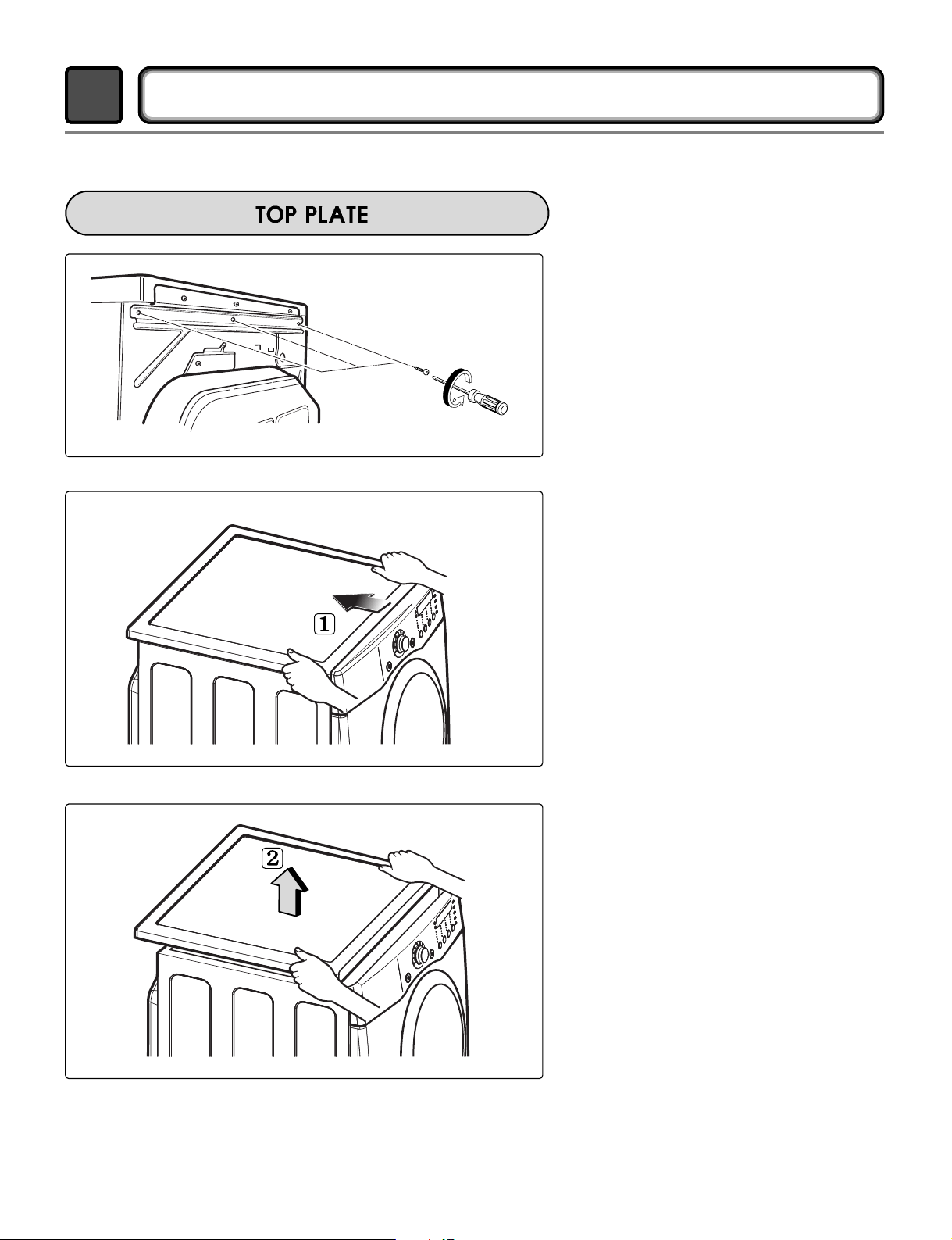
1.
Remove 3 screws on the upper plate.
2.
Push the top plate back ward.
3.
Lift the top plate
31
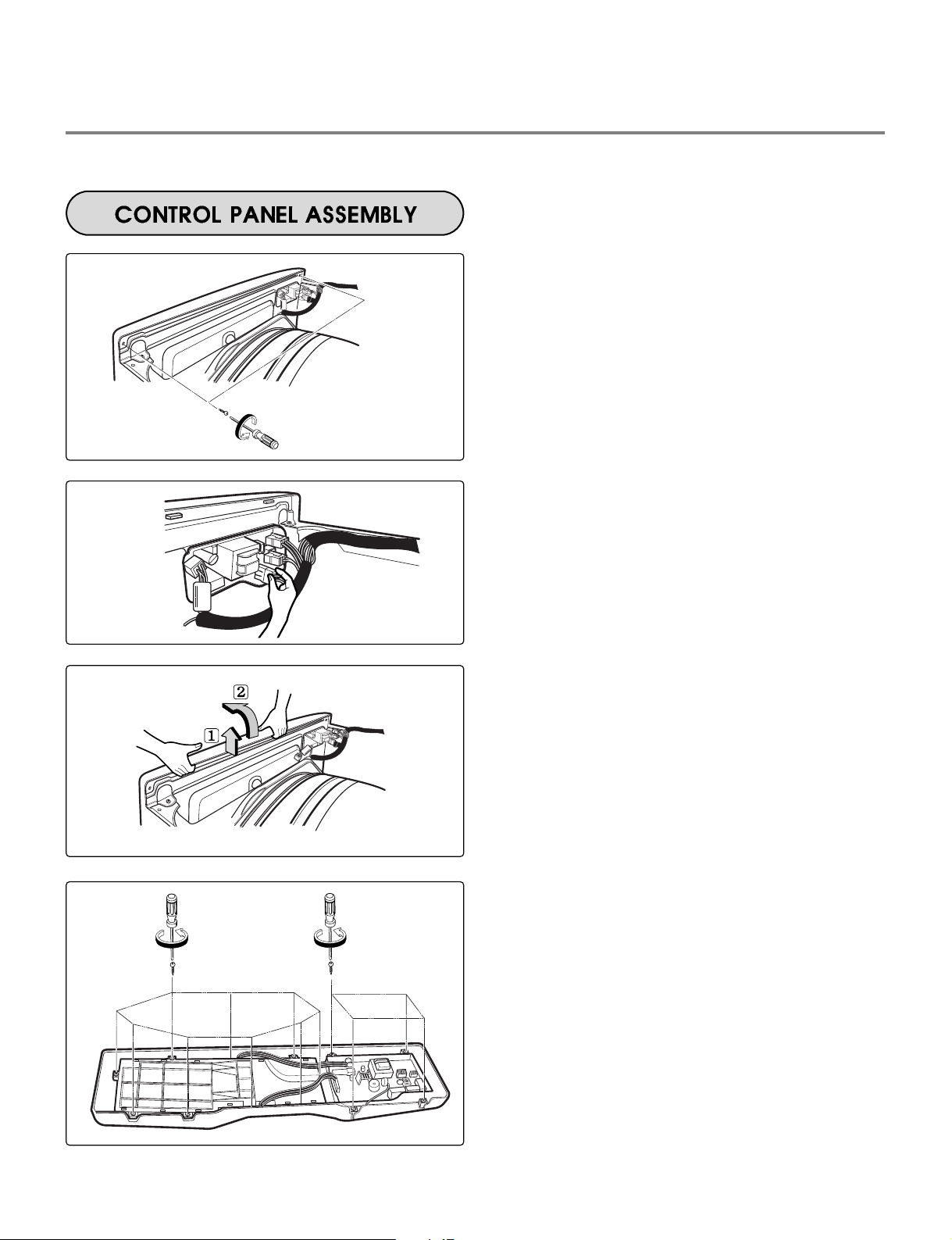
1.
Remove 2 screws on the control panel
frame.
2.
Disconnect the connectors.
3.
Pull the control panel assembly upward and
then forward.
4.
Remove 9 screws on the PWB(PCB)
assembly, display.
5.
Remove 4 screws on the PWB(PCB)
assembly, main.
6.
Disassemble the control panel assembly.
32
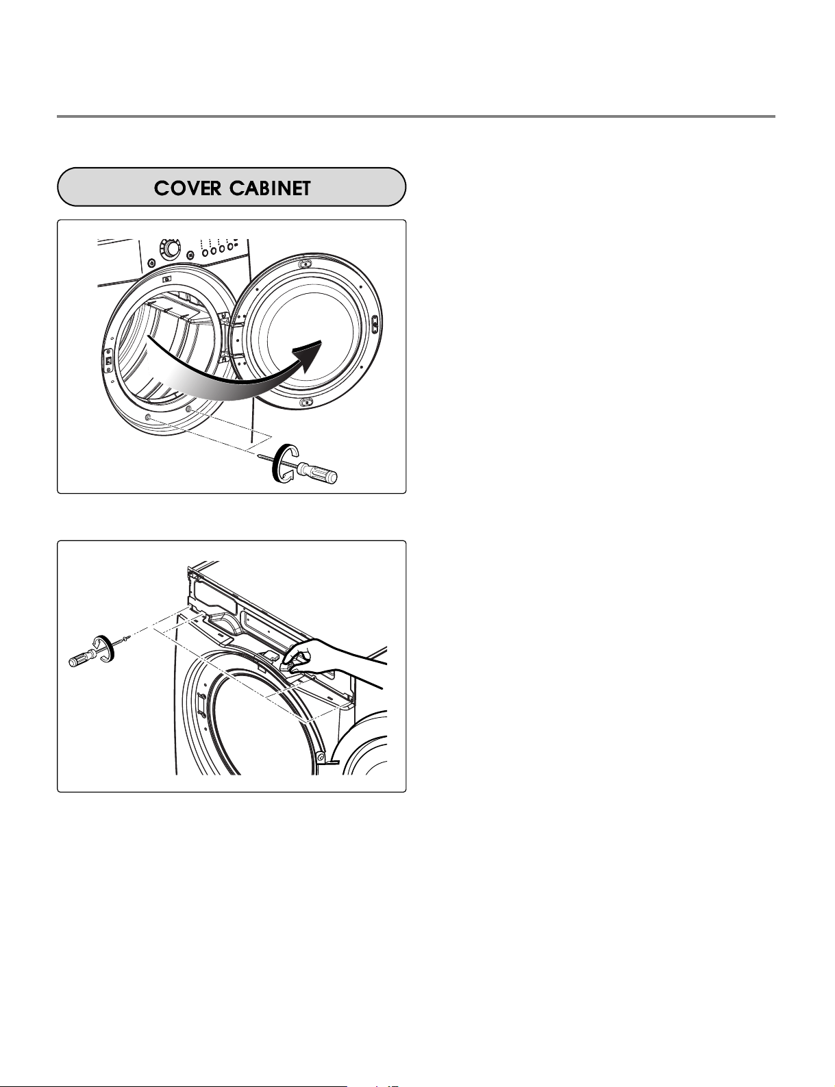
1.
Disassemble the top plate.
2.
Disassemble the control panel assembly.
3.
Disassemble the door assembly.
4.
Remove 2 screws.
5.
Remove 4 screws from the top of cabinet cover.
6.
Disconnect the harness of door switch.
 Loading...