

LG DJM 1000 Service Manual
PIONEER CORPORATION 4-1, Meguro 1-chome, Meguro-ku, Tokyo 153-8654, Japan
PIONEER ELECTRONICS (USA) INC. P.O. Box 1760, Long Beach, CA 90801-1760, U.S.A.
PIONEER EUROPE NV Haven 1087, Keetberglaan 1, 9120 Melsele, Belgium
PIONEER ELECTRONICS ASIACENTRE PTE. LTD. 253 Alexandra Road, #04-01, Singapore 159936
PIONEER CORPORATION 2005
ORDER NO.
RRV3121
DJM-1000
DJ MIXER
DJM-1000
THIS MANUAL IS APPLICABLE TO THE FOLLOWING MODEL(S) AND TYPE(S).
Model Type Power Requirement Remarks
DJM-1000 KUCXJ AC120V
DJM-1000 WYXJ AC220-240V
DJM-1000 RLTXJ AC110-120V / 220-240V
For details, refer to "Important Check Points for good servicing".
T-ZZY APR 2005 printed in Japan
1234
SAFETY INFORMATION
A
This service manual is intended for qualified service technicians ; it is not meant for the casual do-ityourselfer. Qualified technicians have the necessary test equipment and tools, and have been trained
to properly and safely repair complex products such as those covered by this manual.
Improperly performed repairs can adversely affect the safety and reliability of the product and may
void the warranty. If you are not qualified to perform the repair of this product properly and safely, you
should not risk trying to do so and refer the repair to a qualified service technician.
WARNING
This product contains lead in solder and certain electrical parts contain chemicals which are known to the state of California to
cause cancer, birth defects or other reproductive harm.
B
NOTICE
(FOR CANADIAN MODEL ONLY)
Fuse symbols (fast operating fuse) and/or (slow operating fuse) on PCB indicate that replacement parts must
be of identical designation.
Health & Safety Code Section 25249.6 - Proposition 65
REMARQUE
(POUR MODÈLE CANADIEN SEULEMENT)
Les symboles de fusible (fusible de type rapide) et/ou (fusible de type lent) sur CCI indiquent que les pièces
de remplacement doivent avoir la même désignation.
C
(FOR USA MODEL ONLY)
1. SAFETY PRECAUTIONS
The following check should be performed for the
continued protection of the customer and service
technician.
ANY MEASUREMENTS NOT WITHIN THE LIMITS
OUTLINED ABOVE ARE INDICATIVE OF A POTENTIAL
SHOCK HAZARD AND MUST BE CORRECTED BEFORE
RETURNING THE APPLIANCE TO THE CUSTOMER.
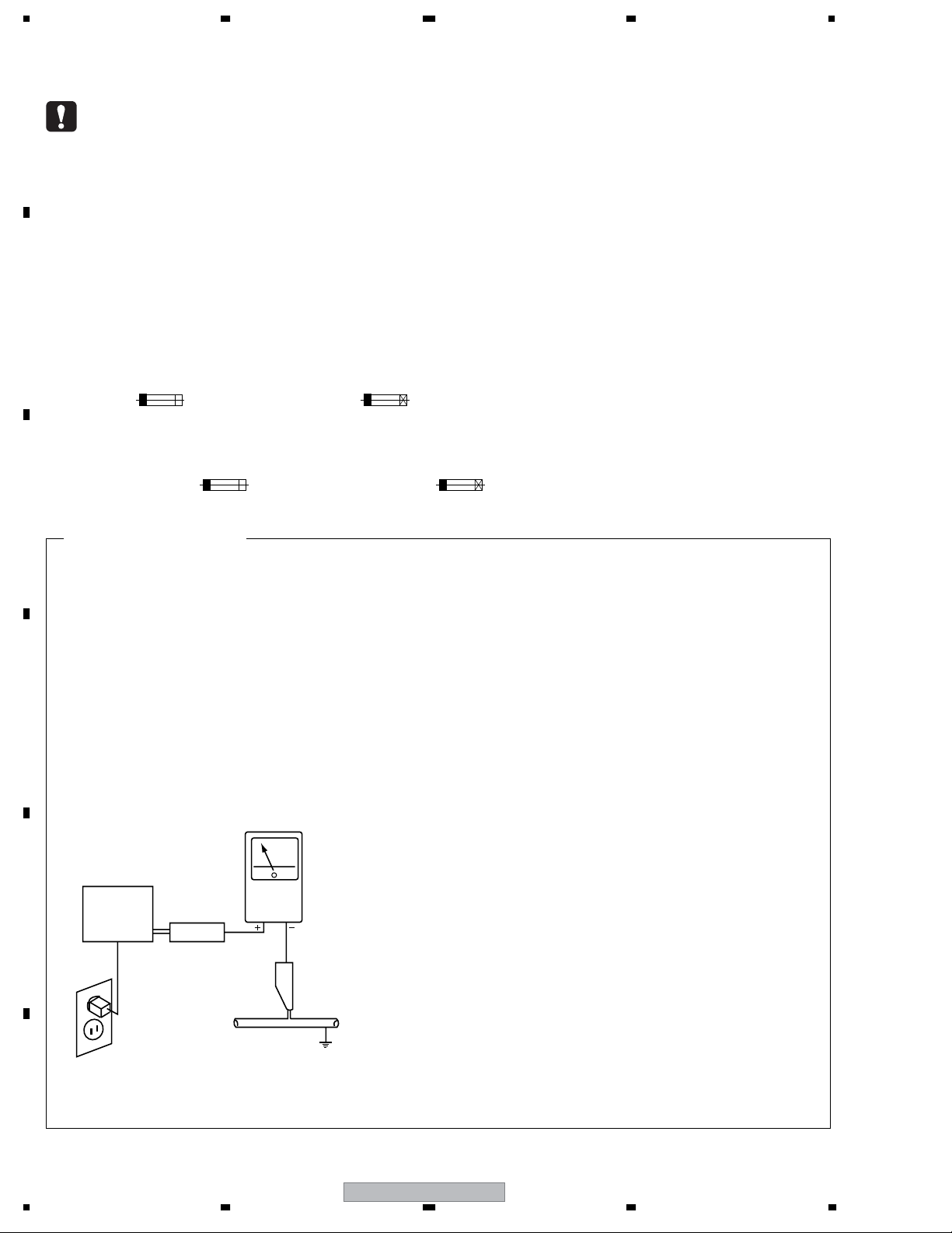
LEAKAGE CURRENT CHECK
Measure leakage current to a known earth ground
(water pipe, conduit, etc.) by connecting a leakage
D
E
current tester such as Simpson Model 229-2 or
equivalent between the earth ground and all exposed
metal parts of the appliance (input/output terminals,
screwheads, metal overlays, control shaft, etc.). Plug
the AC line cord of the appliance directly into a 120V
AC 60 Hz outlet and turn the AC power switch on. Any
current measured must not exceed 0.5 mA.
Reading should
not be above
0.5 mA
Earth
ground
Device
under
test
Also test with
plug reversed
(Using AC adapter
plug as required)
Test all
exposed metal
surfaces
Leakage
current
tester
2. PRODUCT SAFETY NOTICE
Many electrical and mechanical parts in the appliance
have special safety related characteristics. These are
often not evident from visual inspection nor the protection
afforded by them necessarily can be obtained by using
replacement components rated for voltage, wattage, etc.
Replacement parts which have these special safety
characteristics are identified in this Service Manual.
Electrical components having such features are
identified by marking with a > on the schematics and on
the parts list in this Service Manual.
The use of a substitute replacement component which
does not have the same safety characteristics as the
PIONEER recommended replacement one, shown in the
parts list in this Service Manual, may create shock, fire,
or other hazards.
Product Safety is continuously under review and new
instructions are issued from time to time. For the latest
information, always consult the current PIONEER Service
Manual. A subscription to, or additional copies of,
PIONEER Service Manual may be obtained at a nominal
charge from PIONEER.
F
AC Leakage Test
2
1234
DJM-1000
5678
[Important Check Points for Good Servicing]
In this manual, procedures that must be performed during repairs are marked with the below symbol.
Please be sure to confirm and follow these procedures.
1. Product safety
Please conform to product regulations (such as safety and radiation regulations), and maintain a safe servicing environment by
following the safety instructions described in this manual.
1 Use specified parts for repair.
Use genuine parts. Be sure to use important parts for safety.
2 Do not perform modifications without proper instructions.
Please follow the specified safety methods when modification(addition/change of parts) is required due to interferences such as
radio/TV interference and foreign noise.
3 Make sure the soldering of repaired locations is properly performed.
When you solder while repairing, please be sure that there are no cold solder and other debris.
Soldering should be finished with the proper quantity. (Refer to the example)
4 Make sure the screws are tightly fastened.
Please be sure that all screws are fastened, and that there are no loose screws.
5 Make sure each connectors are correctly inserted.
Please be sure that all connectors are inserted, and that there are no imperfect insertion.
6 Make sure the wiring cables are set to their original state.
Please replace the wiring and cables to the original state after repairs.
In addition, be sure that there are no pinched wires, etc.
7 Make sure screws and soldering scraps do not remain inside the product.
Please check that neither solder debris nor screws remain inside the product.
8 There should be no semi-broken wires, scratches, melting, etc. on the coating of the power cord.
Damaged power cords may lead to fire accidents, so please be sure that there are no damages.
If you find a damaged power cord, please exchange it with a suitable one.
9 There should be no spark traces or similar marks on the power plug.
When spark traces or similar marks are found on the power supply plug, please check the connection and advise on secure
connections and suitable usage. Please exchange the power cord if necessary.
0 Safe environment should be secured during servicing.
When you perform repairs, please pay attention to static electricity, furniture, household articles, etc. in order to prevent injuries.
Please pay attention to your surroundings and repair safely.
A
B
C
D
2. Adjustments
To keep the original performance of the products, optimum adjustments and confirmation of characteristics within specification.
Adjustments should be performed in accordance with the procedures/instructions described in this manual.
3. Lubricants, Glues, and Replacement parts
Use grease and adhesives that are equal to the specified substance.
Make sure the proper amount is applied.
4. Cleaning
For parts that require cleaning, such as optical pickups, tape deck heads, lenses and mirrors used in projection monitors, proper
cleaning should be performed to restore their performances.
5. Shipping mode and Shipping screws
To protect products from damages or failures during transit, the shipping mode should be set or the shipping screws should be
installed before shipment. Please be sure to follow this method especially if it is specified in this manual.
56
DJM-1000
E
F
3
7
8

1234
CONTENTS
1. SPECIFICATIONS ............................................................................................................................................ 5
2. EXPLODED VIEWS AND PARTS LIST ............................................................................................................ 6
A
B
C
D
E
2.1 PACKING SECTION .................................................................................................................................. 6
2.2 BOTTOM SECTION................................................................................................................................... 8
2.3 CONTROL PANEL SECTION .................................................................................................................. 10
3. BLOCK DIAGRAM AND SCHEMATIC DIAGRAM ..........................................................................................12
3.1 BLOCK DIAGRAM ................................................................................................................................... 12
3.2 OVERALL WIRING DIAGRAM (1/2) ........................................................................................................ 14
3.3 OVERALL WIRING DIAGRAM (2/2) ........................................................................................................ 16
3.4 DIGITAL MAIN ASSY (1/4)....................................................................................................................... 18
3.5 DIGITAL MAIN ASSY (2/4)....................................................................................................................... 20
3.6 DIGITAL MAIN ASSY (3/4)....................................................................................................................... 22
3.7 DIGITAL MAIN ASSY (4/4)....................................................................................................................... 24
3.8 CH1/CH2 INPUT ASSY ...........................................................................................................................26
3.9 CH3/CH4 INPUT ASSY ...........................................................................................................................28
3.10 CH5/CH6 INPUT ASSY .........................................................................................................................30
3.11 SEND/RETURN ASSY .......................................................................................................................... 32
3.12 BOOTH/REC ASSY ............................................................................................................................... 34
3.13 MASTER ASSY ..................................................................................................................................... 36
3.14 MIC, MIC VR and HP ASSYS ................................................................................................................ 38
3.15 DIGITAL SUB ASSY............................................................................................................................... 40
3.16 VISUAL LINK and MASTER FADER ASSYS.........................................................................................42
3.17 BUS1 ASSY ........................................................................................................................................... 44
3.18 BUS2 ASSY ........................................................................................................................................... 46
3.19 PANEL1 ASSY....................................................................................................................................... 48
3.20 PANEL2 and ISOLATOR ASSYS ........................................................................................................... 50
3.21 PANEL3 ASSY....................................................................................................................................... 52
3.22 CH1/CH3/CH5 FADER, CH2/CH4/CH6 FADER and CROSS FADER ASSYS ..................................... 54
3.23 ACIN, POWER, REG1 and REG2 ASSYS.............................................................................................56
3.24 VOLTAGES............................................................................................................................................. 58
3.25 WAVEFORMS........................................................................................................................................ 65
4. PCB CONNECTION DIAGRAM ..................................................................................................................... 75
4.1 DIGITAL MAIN ASSY...............................................................................................................................76
4.2 CH1/CH2 INPUT and CH3/CH4 INPUT ASSYS...................................................................................... 80
4.3 CH5/CH6 INPUT and SEND/RETURN ASSYS....................................................................................... 82
4.4 BOOTH/REC and MASTER ASSYS........................................................................................................ 84
4.5 MIC, MIC VR, HP and DIGITAL SUB ASSYS .......................................................................................... 86
4.6 VISUAL LINK, MASTER FADER, PANEL2 and ISOLATOR ASSYS........................................................ 88
4.7 BUS1 ASSY ............................................................................................................................................. 92
4.8 BUS2 ASSY ............................................................................................................................................. 94
4.9 PANEL1 ASSY......................................................................................................................................... 96
4.10 PANEL3 ASSY..................................................................................................................................... 100
4.11 CH1/CH3/CH5 FADER, CH2/CH4/CH6 FADER and CROSS FADER ASSYS ................................... 104
4.12 ACIN, POWER, REG1 and REG2 ASSYS...........................................................................................106
5. PCB PARTS LIST ......................................................................................................................................... 110
6. ADJUSTMENT ............................................................................................................................................. 119
7. GENERAL INFORMATION........................................................................................................................... 120
7.1 DIAGNOSIS ........................................................................................................................................... 120
7.1.1 TEST MODE .................................................................................................................................... 120
7.1.2 POWER ON SEQUENCE................................................................................................................ 128
7.1.3 TROUBLE SHOOTING.................................................................................................................... 129
7.1.4 DISASSEMBLY................................................................................................................................ 130
7.2 PARTS.................................................................................................................................................... 139
7.2.1 IC ..................................................................................................................................................... 139
8. PANEL FACILITIES ...................................................................................................................................... 163
F
4
1234
DJM-1000

5678
1. SPECIFICATIONS
1. General Specifications
Power supply voltage (KUCXJ) ..............................AC 120 V, 60 Hz
Power supply voltage (WYXJ) ...................AC 220-240 V, 50/60 Hz
Power supply voltage (RLTXJ) ....
Power consumption (KUCXJ) ...................................................63 W
Power consumption (WYXJ, RLTXJ) ........................................62 W
Operating temperature ...................+5°C to +35°C (+41°F to +95°F)
Operating humidity ...........................5 % to 85 % (no condensation)
Weight ..............................................................12.1 kg (26 lb 11 oz)
External dimensions ................482 (W) x 359.3 (D) x 187.5 (H) mm
AC 110-120 V/220-240 V, 50/60 Hz
(19 (W) x 14-5/16 (D) x 7-3/8 (H) in)
2. Audio Section
Sampling rate .........................................................................96 kHz
A/D, D/A converter .................................................................24 bits
Frequency response ................................................20 Hz to 20 kHz
S/N ratio (at full scale)
LINE .................................................................................104 dB
PHONO ..............................................................................88 dB
MIC .....................................................................................84 dB
Distortion (LINE-MASTER1) ................................................0.005 %
Headroom.................................................................................19 dB
Input level
PHONO .............................................................–52 dBu (47 kΩ)
MIC, SUBMIC.......................................................–52 dBu (3 kΩ)
CD/LINE, LINE ..................................................–12 dBu (22 kΩ)
RETURN ............................................................–12 dBu (22 kΩ)
Output level
MASTER1 ...........................................................+2 dBu (600 Ω)
MASTER2 ...........................................................+2 dBu (10 kΩ)
REC .....................................................................–8 dBu (10 kΩ)
BOOTH ...............................................................+2 dBu (600 Ω)
SEND .................................................................–12 dBu (10 kΩ)
PHONES ............................................................+8.5 dBu (32 Ω)
Crosstalk (LINE) ......................................................................88 dB
Channels .........................................................................................6
Channel equalizer
HI .........................................................–26 dB to +6 dB (13 kHz)
MID ........................................................–26 dB to +6 dB (1 kHz)
LOW.......................................................–26 dB to +6 dB (70 Hz)
Microphone equalizer
HI ...........................................................–6 dB to +6 dB (10 kHz)
LOW.......................................................–6 dB to +6 dB (100 Hz)
Booth monitor equalizer
HI ...........................................................–6 dB to +6 dB (10 kHz)
LOW.......................................................–6 dB to +6 dB (100 Hz)
3. Input output connectors
PHONO input connectors
RCA pin jack ..............................................................................6
CD/LINE, LINE input connectors
RCA pin jack ..............................................................................6
Phone jack (φ6.3 mm) .....................................................................4
MIC, SUBMIC input connectors
XLR connector/Phone jack (φ6.3 mm) .......................................1
Phone jack (φ6.3 mm) ................................................................2
DIGITAL coaxial input connectors
RCA pin jack ..............................................................................4
RETURN input connectors
Phone jack (φ6.3 mm) ................................................................2
MASTER output connectors
XLR connector............................................................................1
RCA pin jack ..............................................................................1
BOOTH output connectors
Phone jack (φ6.3 mm) ................................................................2
REC output connectors
RCA pin jack ..............................................................................1
SEND output connectors
Phone jack (φ6.3 mm) ................................................................2
DIGITAL coaxial output connector
RCA pin jack ..............................................................................1
Digital link connectors (EFX 1, 2, SOUND 1, 2, VISUAL)
Mini DIN .....................................................................................5
MIDI OUT connector
5P DIN .......................................................................................1
4. Accessories
Operating instructions .....................................................................1
Power cord ......................................................................................1
Warranty (KUCXJ only) ...................................................................1
Appearance and specifications are subject to change without
notice.
A
B
C
D
Accessories
Power cord
(KUCXJ : DDG1028)
(WYXJ, RLTXJ : ADG7062)
56
Operating Instructions
Warranty (KUCXJ type only)
DJM-1000
7
E
F
5
8
1234
2. EXPLODED VIEWS AND PARTS LIST
NOTES:
A
Parts marked by "NSP" are generally unavailable because they are not in our Master Spare Parts List.
The mark found on some component parts indicates the importance of the safety factor of the part.
Therefore, when replacing, be sure to use parts of identical designation.
Screws adjacent to mark on product are used for disassembly.
For the applying amount of lubricants or glue, follow the instructions in this manual.
(In the case of no amount instructions, apply as you think it appropriate.)
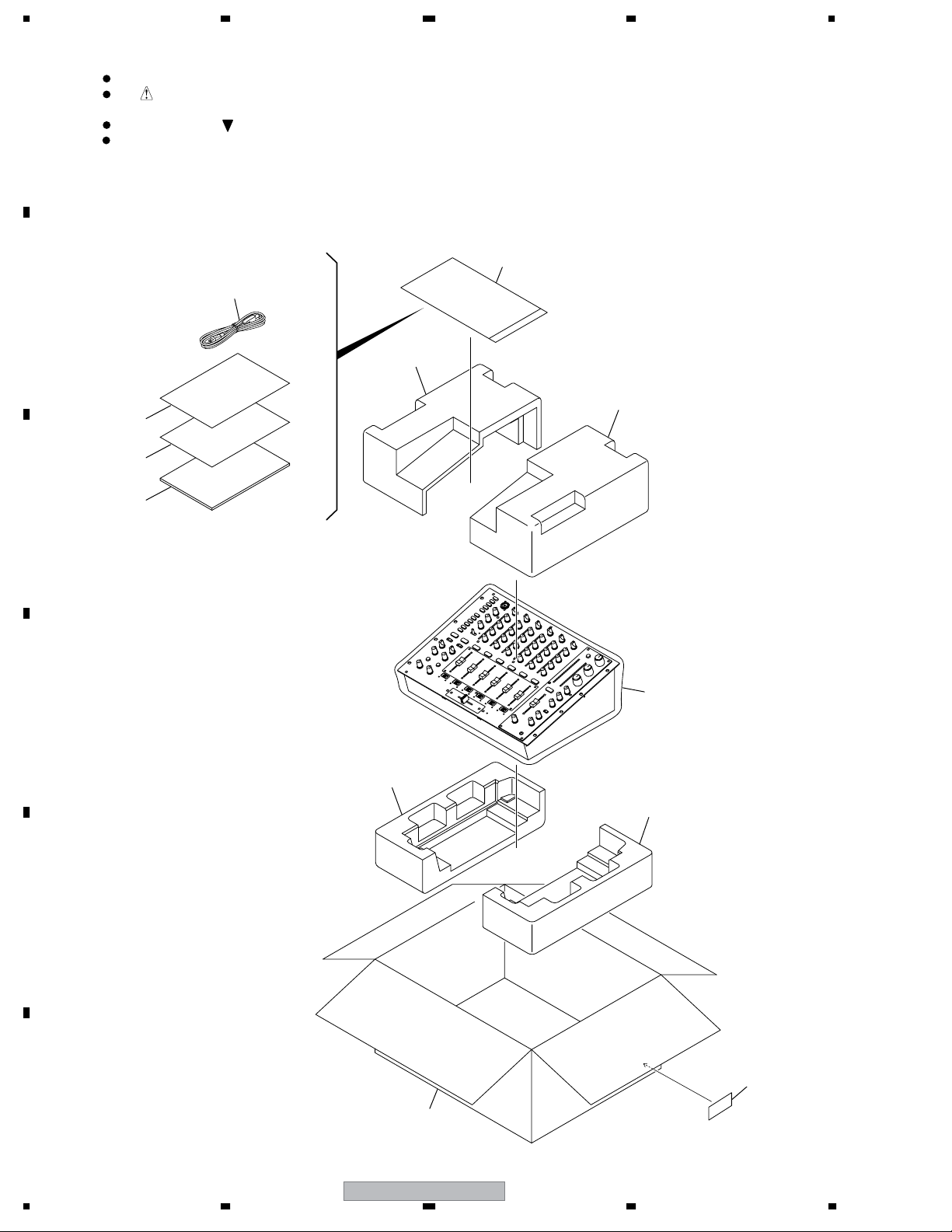
2.1 PACKING SECTION
B
3
2
C
4
5
1
7
(1/2)
7
(2/2)
9
D
6
(1/2)
(2/2)
6
E
10
F
8
6
1234
DJM-1000
>
>
5678
(1) PACKING SECTION PARTS LIST
No. Description Part No.
Mark
1Power Cord See Contrast table (2)
NSP 2 Warranty See Contrast table (2)
NSP 3 User Seat DRM1262
4 Operating Instructions See Contrast table (2)
NSP 5 Polyethylene Bag AHG7117
(0.06 x 230 x 340)
6 Bottom Pad DHA1641
7Top Pad DHA1642
8Packing Case See Contrast table (2)
9Packing Sheet RHC1023
NSP 10 Label VRW1629
(2) CONTRAST TABLE
DJM-1000/KUCXJ, WYXJ and RLTXJ are constructed the same except for the following:
Mark No. Symbol and Description
1Power Cord DDG1028 ADG7062 ADG7062
NSP 2 Warranty ARY7043 Not used Not used
4 Operating Instructins (English) DRB1371 Not used Not used
4 Operating Instructins (English/ French/
German/ Italian/ Duch/ Spanish)
4 Operating Instructins
(English/ Spanish/ Chinese)
8Packing Case DHG2501 DHG2502 DHG2503
DJM-1000
/KUCXJ
Not used DRB1372 Not used
Not used Not used DRB1373
DJM-1000
/WYXJ
DJM-1000
/RLTXJ
A
B
C
D
E
F
56
DJM-1000
7
7
8
1234
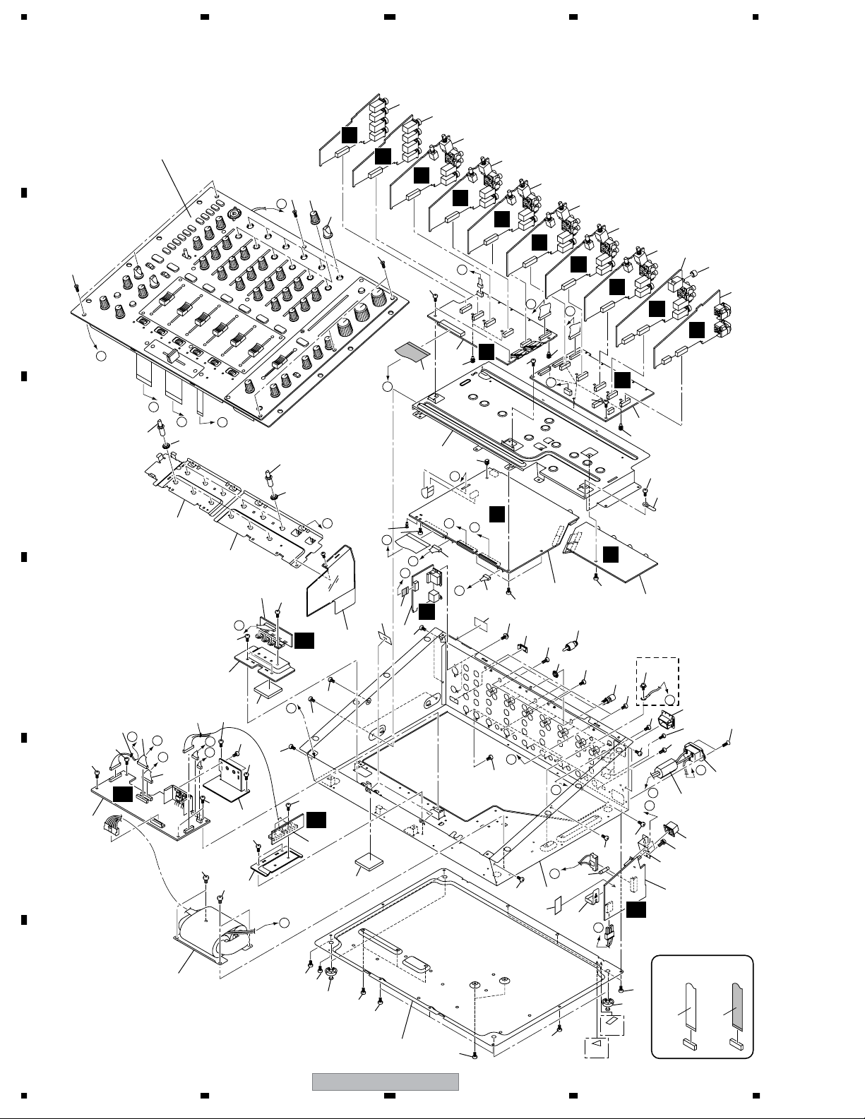
2.2 BOTTOM SECTION
A
Refer to "2.3 CONTROL PANEL SECTION".
B
C
52
L
P
O
34
51
5
5
E
E
B
52
41
Q
40
56
55
2
2
3
B
C
C
Q
E
3
4
4
6
D
D
D
F
46
7
G
55
26
N
O
55
11
26
55
49
N
10
26
17
K
N
29
35
51
26
M
23
A
O
K
B
22
65
61
G
61
55
1
55
44
54
51
H
A
38
64
31
16
25
×12
55
55
55
43
55
55
55
62
8
KUCXJ
Only
J
45
55
H
54
I
20
61
30
12
59
42
52
J
19
AA
I
P
C
L
L
AD
60
55
AC
14
55
G
27
58
48
28
55
K
M
18
9
55
36
37
15
55
F
63
53
55
57
58
55
55
C
B
55
53
33
47
55
55
55
A
D
63
24
F
55
55
E
D
24
AB
E
13
21
F
8
1234
55
55
39
55
55
DJM-1000
32
55
55
KUCXJ Only
67
66
55
39
WYXJ
Only
NON-CONTACT
SIDE
CONTACT SIDE
>
>
>
>
5678
(1) BOTTOM SECTION PARTS LIST
No. Description Part No.
Mark
1 DIGITAL MAIN Assy DWG1586
2 CH1/CH2 INPUT Assy DWX2501
3 CH3/CH4 INPUT Assy DWX2502
4 CH5/CH6 INPUT Assy DWX2503
5 SEND/RETURN Assy DWX2408
No. Description Part No.
Mark
36 PCB Stay V (A) Assy DXB1856
37 PCB Stay V (B) Assy DXB1857
NSP 38 Chassis See Contrast table (2)
39 Leg Assy REC-434
40 Rotary SW Knob DAA1167
A
6 BOOTH/REC Assy DWX2409
7 MASTER Assy DWX2410
8 DIGITAL SUB Assy DWX2414
9 VISUAL LINK Assy DWX2413
10 BUS1 Assy DWX2422
11 BUS2 Assy DWX2423
12 ACIN Assy See Contrast table (2)
13 POWER Assy DWR1384
14 REG1 Assy DWR1385
15 REG2 Assy DWR1386
16 Short Pin Plug AKM7008
17 40P Flexible Cable DDD1288
18 10P Flexible Cable DDD1289
19 AC Inlet Assy See Contrast table (2)
20 Ferrite Core DTH1195
21 Power Transformer See Contrast table (2)
22 Connector PF04EE-S07
23 Connector PF06EE-S15
24 Connector PF10EE-S30
25 Fuse (FU1) See Contrast table (2)
26 Card Spacer AEC7214
27 Shield Plate (A) DEC2839
28 Shade Sheet A DEC2842
29 PCB Stay (H) DNF1704
30 Power Switch Stay DNF1705
41 Rotary Knob B DAA1171
42 Power Knob DAC2133
43 Earth Terminal with Knob DKE1014
44 Blind Cap DNK4218
45 Power Knob Guard DNK4335
46 Select Knob (S) DAA1166
47 Heatsink A DNG1092
48 Nyron Rivet (3 x 4.5) RBM-003
NSP 49 Cord Clamper ZCB-069Z
50 Flange Nut M12 DBN1012
51 Flange Nut M7 DBN1011
52 Screw CMZ30P100FTB
53 Screw BBZ40P060FTC
54 Screw BPZ30P080FTB
55 Screw BBZ30P060FTB
56 Screw CMZ30P100FNI
57 Heatsink B DNG1093
NSP 58 Silicone Sheet C DEB1764
59 Screw BBZ26P060FTB
60 Screw BBZ30P080FTC
61 Screw PMH30P100FTB
62 Screw See Contrast table (2)
NSP 63 Binder ZCA-BK1
NSP 64 Fuse Card DAX1015
NSP 65 Label VRW1629
B
C
D
31 Power PCB Stay DNF1716
32 Bottom Plate DNH2620
NSP 33 Heatsink Plate B DNH2644
34 Extension Shaft (L) DNK4336
35 Extension Shaft (L2) DNK4491
66 Label (WEEE) See Contrast table (2)
67 Label See Contrast table (2)
(2) CONTRAST TABLE
DJM-1000/KUCXJ, WYXJ and RLTXJ are constructed the same except for the following:
Mark No. Symbol and Description
12 ACIN Assy DWR1383 DWR1383 DWR1399
>
>
>
>
>
NSP 38 Chassis DNA1304 DNA1306 DNA1326
19 AC Inlet Assy (3P) DKP3730 Not used Not used
19 AC Inlet Assy (2P) Not used DKP3731 DKP3731
21 Power Transformer DTT1179 DTT1178 DTT1180
25 Fuse (FU1 : 2A) REK1111 Not used Not used
25 Fuse (FU1 : 1.6A) Not used REK1024 REK1024
62 Screw PMH40P080FTC Not used Not used
66 Label (WEEE) Not used ARW7322 Not used
66 Label DRW1975 Not used Not used
DJM-1000
/KUCXJ
DJM-1000
/WYXJ
DJM-1000
56
DJM-1000
/RLTXJ
7
E
F
9
8
1234
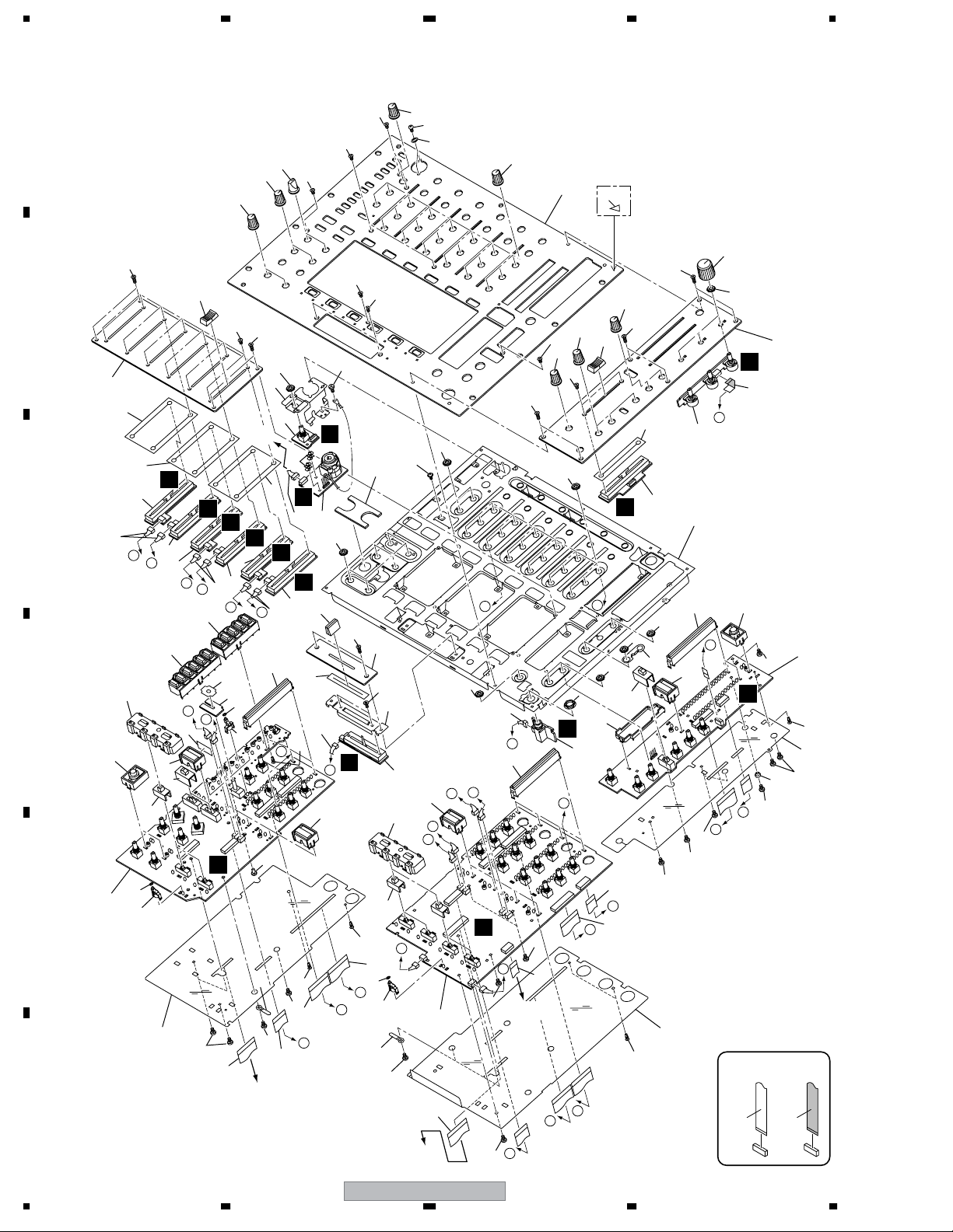
2.3 CONTROL PANEL SECTION
A
71
54
76
65
15
78
53
48
82
KUCXJ Only
50
73
70
47
R
22
Q
7
73
71
54
75
54
53
73
60
38
69
81
I
69
4
M
J
64
40
58
69
57
69
28
69
69
25
H
64
F
E
D
C
77
J
61
43
3
J
57
72
Q
72
6
Q
67
34
72
31
72
P
O
72
20
P
21
S
H
To BUS2
CN306
72
23
G
72
8
O
72
33
67
16
M
L
71
52
54
71
49
71
71
59
B
74
71
69
To BUS1
CN510
U
11
13
E
42
2
44
37
H
27
1
X
V
Y
14
26
63
F
45
37
37
T
9
12
10
W
C
D
26
55
C
26
A
B
71
72
I
30
69
71
56
64
36
65
D
35
58
57
29
A
79
B
66
39
24
67
I
61
62
P
79
E
5
66
51
57
46
80
41
Z
G
62
67
18
68
67
72
18
32
72
72
K
19
17
To DIGITAL MAIN
F
CN202
79
M
66
L
68
72
10
To DIGITAL MAIN
CN201
72
K
NON-CONTACT
SIDE
CONTACT SIDE
DJM-1000
1234

5678
CONTROL PANEL SECTION PARTS LIST
No. Description Part No.
Mark
1 MIC Assy DWX2411
2 MIC VR Assy DWX2466
3 HP Assy DWX2412
4 MASTER FADER Assy DWX2421
5PANEL1 Assy DWX2427
6PANEL2 Assy DWX2428
7 ISOLATOR Assy DWX2425
8PANEL3 Assy DWX2426
9 CH1/CH3/CH5 FADER Assy DWX2416
10 CH1/CH3/CH5 FADER Assy DWX2418
11 CH1/CH3/CH5 FADER Assy DWX2443
12 CH2/CH4/CH6 FADER Assy DWX2415
13 CH2/CH4/CH6 FADER Assy DWX2417
14 CH2/CH4/CH6 FADER Assy DWX2442
15 CROSS FADER Assy DWX2424
16 31P Flexible Cable DDD1280
17 28P Flexible Cable DDD1281
18 31P Flexible Cable DDD1282
19 20P Flexible Cable DDD1283
20 13P Flexible Cable DDD1284
21 28P Flexible Cable DDD1285
22 7P Flexible Cable DDD1286
23 10P Flexible Cable DDD1287
24 Connector PF03PP-R10
25 Connector PF04PP-R07
26 Connector PF04PP-R10
27 Connector PF05PP-R10
28 Earth Spring DBK1265
29 Shade Spacer A DEB1729
30 Shade Spacer B DEB1730
31 POM Bush (M3) DEC2397
32 Insulation Sheet (A) DEC2762
33 Insulation Sheet (B) DEC2763
34 Insulation Sheet (C) DEC2764
35 Shade Sheet B DEC2843
36 SW Packing DEC2848
37 CH Fader Packing DEC2865
38 Master Fader Packing DEC2866
39 Fader Packing DEC2867
NSP 40 Panel Stay DND1253
41 CRF Stay DNF1706
No. Description Part No.
Mark
42 MIC. Stay DNF1720
43 Master Fader Holder DNK4374
NSP 44 PC Support VEC1508
45 CHF Panel DAH2414
46 CRF Panel DAH2415
47 Master Panel DNB1135
48 Control Panel DNB1136
49 Rotary Knob (SS) DAA1164
50 VR Knob (ISO) DAA1165
51 Nyron Rivet DEC2870
52 Rotary SW Knob DAA1167
53 Rotary Knob A DAA1170
54 Rotary Knob B DAA1171
55 Set Knob (LINK) DAC2213
56 Set Knob (FS) DAC2214
57 CUE Knob DAC2215
58 ISO Knob DAC2216
59 CHF Knob DAC2217
60 MF Knob DAC2218
61 Slide SW Cap (A) DAC2219
62 Slide SW Cap (B) DAC2220
63 Slider Knob (L) DNK4210
64 Level Meter Lens DNK4332
65 Set Lens DNK4333
66 LED Lens DNK4334
67 Nyron Rivet (3 x 4.5) RBM-003
NSP 68 Cord Clamper ZCB-069Z
69 Flange Nut M9 DBN1008
70 Flange Nut M7 DBN1011
71 Screw CMZ30P100FTB
72 Screw BBZ30P060FTB
73 Screw CMZ30P100FNI
74 Screw CMZ30P050FTB
75 Screw CMZ30P050FNI
76 Screw BPZ30P120FTB
77 Flange Nut M12 DBN1012
78 PC Washer DEC2868
79 Poly. Slider Washer WA26D080D025
80 Screw DBA1262
81 Screw AMZ26P040FTC
82 Label See Contrast table (2)
A
B
C
D
E
(2) CONTRAST TABLE
DJM-1000/KUCXJ, WYXJ and RLTXJ are constructed the same except for the following:
Mark No. Symbol and Description
82 Label DRW1975 Not used Not used
DJM-1000
/KUCXJ
DJM-1000
/WYXJ
DJM-1000
56
DJM-1000
/RLTXJ
7
F
11
8
1234
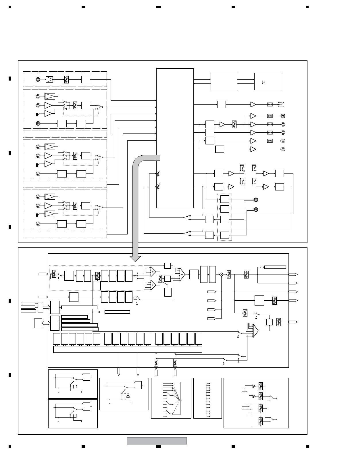
3. BLOCK DIAGRAM AND SCHEMATIC DIAGRAM
3.1 BLOCK DIAGRAM
A
MIC
MIC AMP
PHONO AMP
BUF.
BUF.
PHONO AMP
BUF.
BUF.
PHONO AMP
BUF.
MIC AMP
same as CH1
same as CH3
DIR
same as CH5
A/D
TRIM
A/D
SRCDIR
TRIM
A/D
SRCDIR
TRIM
A/D
SRC
MIC
CH1
PHONO
LINE/CD
B
LINE
SOUND
CH2
CH3
PHONO
LINE/CD
LINE
DIGITAL
CH4
C
CH5
PHONO
LINE/CD
SUBMIC
DIGITAL
CH6
MIC LEVEL
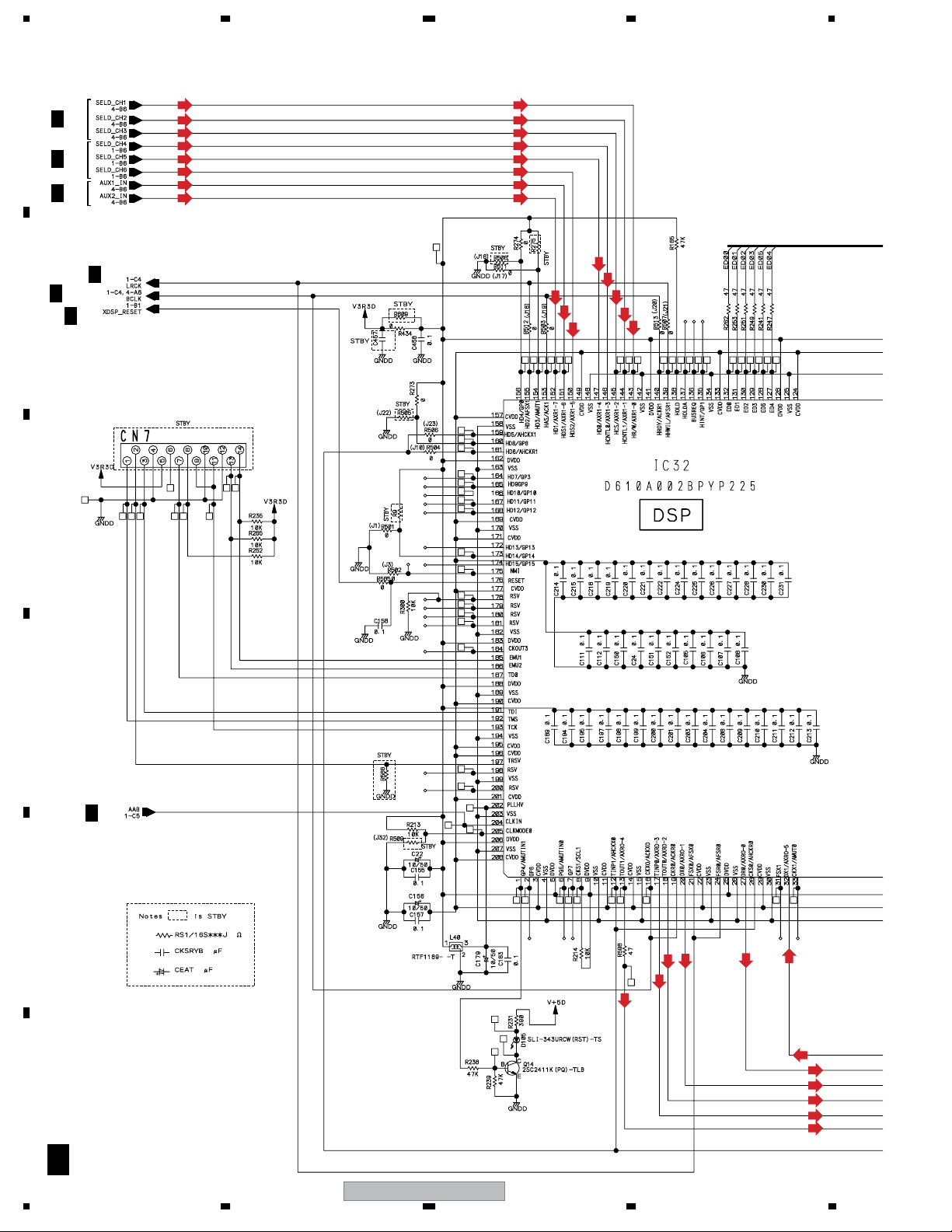
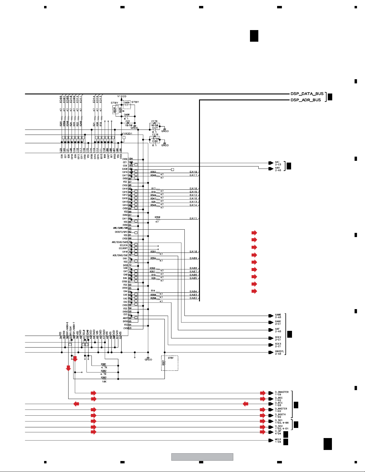
DSP
MIC
CH1
CH2
CH3
CH4
CH5
CH6
RETURN 1
RETURN 2
BUS
HP
MASTER
BOOTH
REC
SEND 1
SEND 2
SEND RETURN1
EFX1
SEND RETURN2
EFX2
D/A
D/A
D/A
SRC
SRC
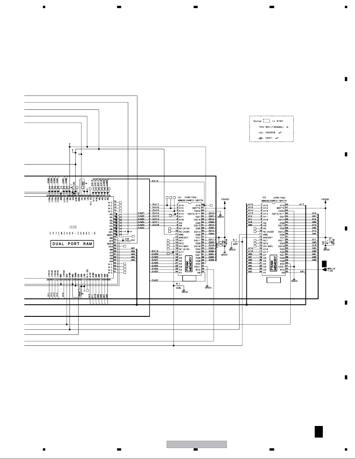
DUAL PORT
RAM
D/A
DIT
D/A
D/A
DIT
DIT
DIR
DIR
ATT
SEND1 RETURN1
SEND2 RETURN2
-COM
MUTE
MUTE
MUTE
MUTE
MUTE
EFX1 (1/2)
EFX2 (1/2)
PHONES
MASTER1
MASTER2
BOOTH
REC
DIGITAL OUT
A/D
A/D
CHn IN
MIC IN
A/D
12
Bit
Bus
Bus
DSP
CH1 ó CH6 Common
Digital Trim
Digital
3-Band
CHn
EQ
Analog
2-Band
A/D
Variously Fader Volumesí value
Input
Logic
CHn Level LED detect
A/D
Master Level LED detect
Input
Fader Start/CUE Back Trimming
Logic
Variously Volumesí & SWsí value
Send
Send
Send
Ret1
Ret1
Ret2
Post
Pre
Pre
CHn
CHn
CHn
MIC
CHn
Fader
Send
Send
Ret1
Ret2
Pre
CHn
EQ
Send
Ret2
Post
CHn
Pre
CHn
Send
Ret1
CHn
Send
Send
Send
Send
Ret2
Ret1
Aux
Post
Post
CHn
CHn
CHn
CHn
CH
Fader
Curve
Send
Send
Send
MIC
Send
Ret2
Aux
Post
MIC
Send
Send
Ret2
Ret1
Pre
Post
MIC
MIC
Ret1
Post
MIC
CHn level LED detect
Send
Send
Ret1
Ret2
Aux
CHn
Pre
MIC
Aux
CF Assign
Aux
Aux
MIC
Send
Ret2
Post
MIC
Thru
A
B
Talk Over
MIC On
MIC Off
Send
Ret1
Aux
MIC
CHn
CHn
Send
Ret2
Aux
MIC
D
CHn Fader
Cross Fader
Master Fader
DUAL
PORT
RAM
E
Send1,2 Selector
Return1
Level
Send / Ret1,2 (PreXXX)
Send/Return SW
IN
PreXXX
to Send1,2 Selector from Return1,2 Selector
Send / Ret1,2 (PostXXX)
Send/Return SW
IN
F
PostXXX
to Send1,2 Selector from Return1,2 Selector
XXX
OUT
CMP
Off
On
AuxPre
Post
PreXXX
XXX
OUT
CMP
Off
On
AuxPre
Post
PostXXX
SEND
OUT1
Send / Ret1,2 (AuxXXX) Send1,2 Selector Return1,2 Selector
IN
AuxXXX
to Send1,2 Selector from Return1,2 Selector
XXX : CHn (n=1 ñ 6), MIC, Mast
SEND
OUT2
Send/Return SW
Off
On
AuxPre
Post
AuxXXX
XXX
CMP
RETURN
OUT
Talk
Over
Cross Fader
A
Talk
Over
B
Cross
Fader
Curve
Send
Send
Ret1
Ret2
Pre
Pre
Mast
Mast
Return1,2 Selector
Return2
Level
RETURN
IN1
CHn
Pre CHn
Post CHn
Aux CHn
Pre MIC
Post MIC
Aux MIC
Pre Mast
Post Mast
Aux Mast
CHn
Send
Send
Ret1
Ret2
Post
Post
Mast
Mast
IN2
Send
Ret1
Aux
Mast
3-Band
CHn
EQ
Send
Ret2
Aux
Mast
Send
Ret1
Pre
Post
Aux
Mast
Ret1
Aux
CHn
Ret2
Aux
CHn
Ret1
Aux
MIC
Ret2
Aux
MIC
Send
Master balance
Ret2
Pre
Post
Aux
Mast
Return1 CUE
CHn CUE
Return2 CUE
On
Off
Master Fader
Master Fader
CHn CUE
On
Off
On
Off
HP Mix
SEND
OUT1,2
RETURN
IN1,2
CHn
Pre CHn
Post CHn
Aux CHn
Pre MIC
Post MIC
Aux MIC
Pre Mast
Post Mast
Aux Mast
Master IN
CUE IN
L
R
L
R
2-Band
Booth
Master CUE
On
Off
Master
CUE
Mix L
Mix R
Master LED detect
EQ
Master
CUE
R
L
Booth Level
HP Level
HP
Mix
Mono Split
Stereo
Mono Split
Stereo
Mix OUT
L
Mix OUT
R
MASTER
OUT
MASTER
DIGITAL OUT
REC OUT
BOOTH OUT
HP OUT
12
DJM-1000
1234

5678
A
B
C
D
E
56
DJM-1000
F
13
7
8
1234
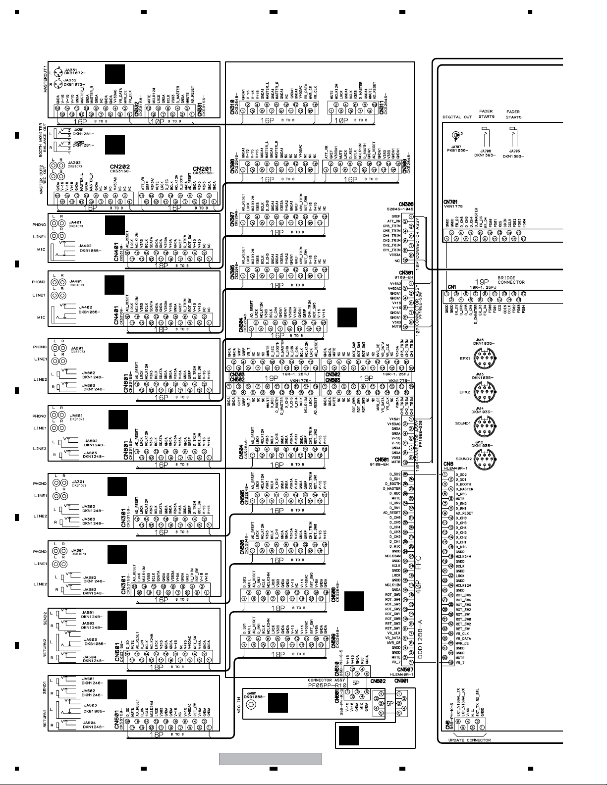
3.2 OVERALL WIRING DIAGRAM (1/2)
A
B
C
MASTER ASSY
(DWX2410)
G
BOOTH/REC ASSY
(DWX2409)
F
CH5/CH6 INPUT ASSY
(DWX2407)
D
CH5/CH6 INPUT ASSY
(DWX2407)
D
CH3/CH4 INPUT ASSY
(DWX2406)
C
O
BUS2 ASSY (DWX2423)
CH3/CH4 INPUT ASSY
(DWX2406)
C
D
CH1/CH2 INPUT ASSY
(DWX2405)
B
CH1/CH2 INPUT ASSY
(DWX2405)
B
E
N
SEND/RETURN ASSY
(DWX2408)
E
SEND/RETURN ASSY
(DWX2408)
E
F
H
MIC ASSY
(DWX2411)
BUS1 ASSY (DWX2422)
DKP3681DKN1389
14
MIC VR ASSY
(DWX2466)
I
DJM-1000
1234
5678
A
B
A
DIGITAL SUB
K
ASSY
(DWX2414)
T
CH1
CH1/CH3/CH5 FADER
ASSY (DWX2416)
CH2/CH4/CH6 FADER
W
CH2
ASSY (DWX2415)
CH1/CH3/CH5 FADER
U
CH3
ASSY (DWX2418)
ASSY (DWX2417)
CH2/CH4/CH6 FADER
X
CH4
V
CH5
CH1/CH3/CH5 FADER
ASSY (DWX2443)
Y
CH6
CH2/CH4/CH6 FADER
ASSY (DWX2442)
PANEL2 ASSY
(DWX2428)
Z
CROSS FADER
ASSY (DWX2424)
ISOLATOR ASSY
(DWX2425)
R
B
C
P
A 1/4- A 4/4
A
DIGITAL MAIN ASSY (DWG1586)
PANEL1 ASSY
(DWX2427)
VISUAL LINK ASSY
(DWX2413)
L
S
PANEL3 ASSY
(DWX2426)
Q
J
MASTER FADER
HP ASSY
(DWX2412)
D
ASSY (DWX2421)
M
E
F
56
DJM-1000
15
7
8
1234
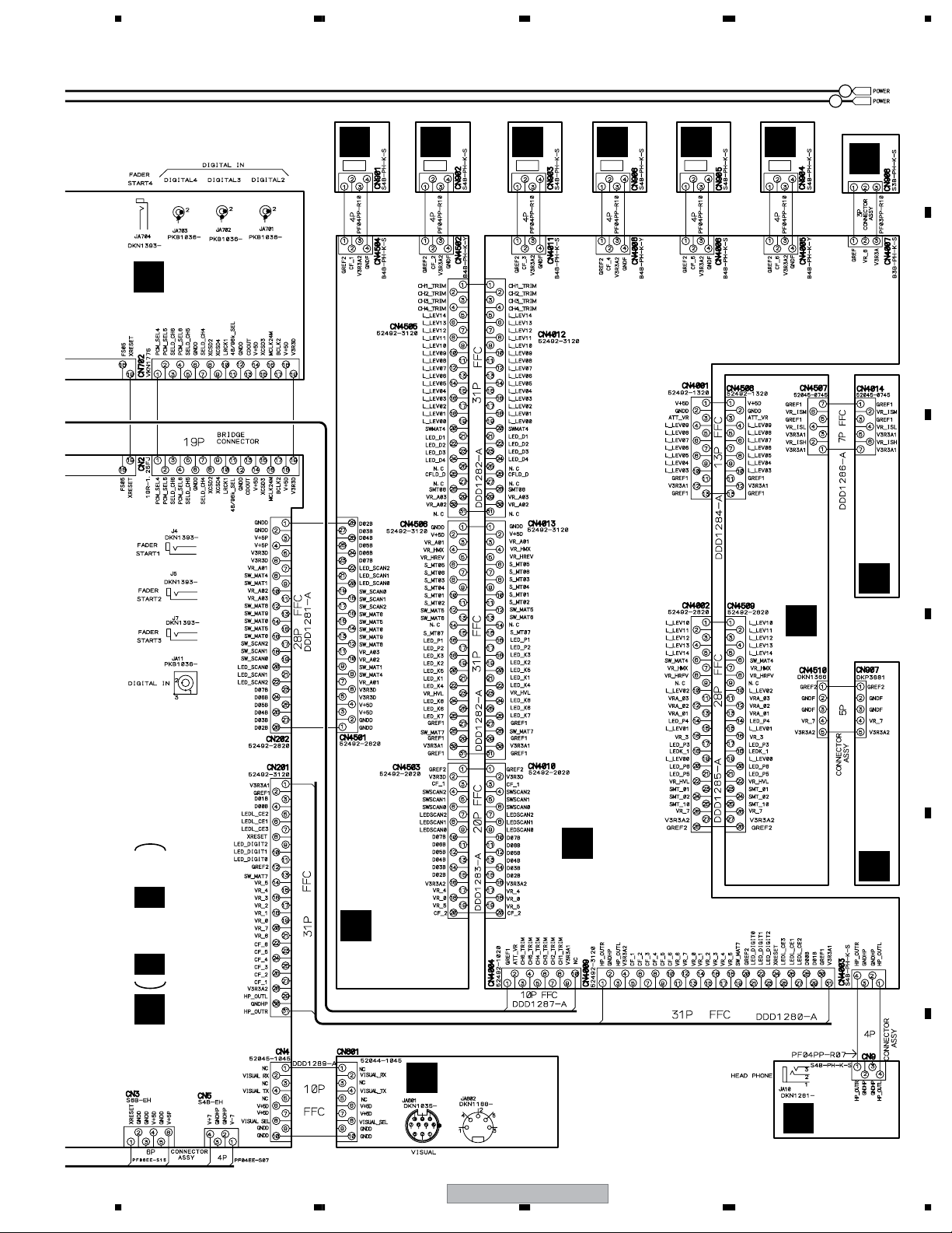
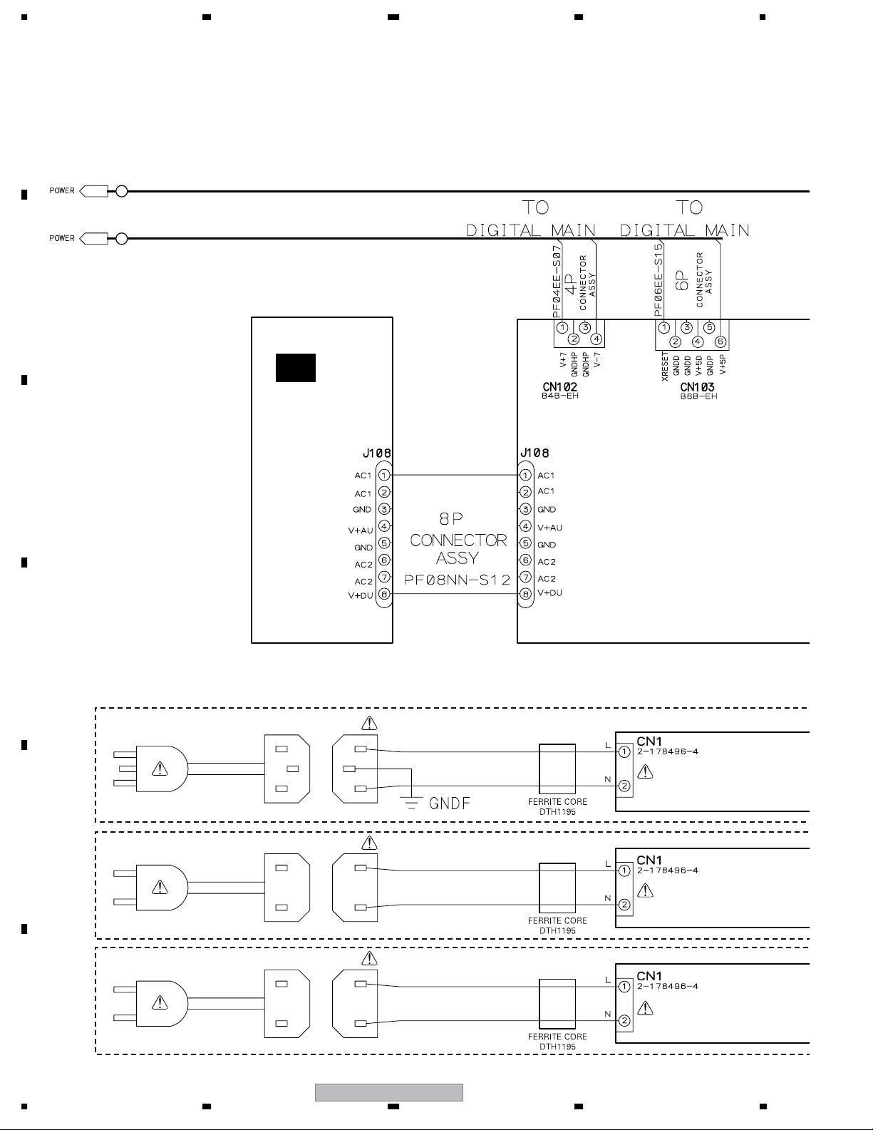
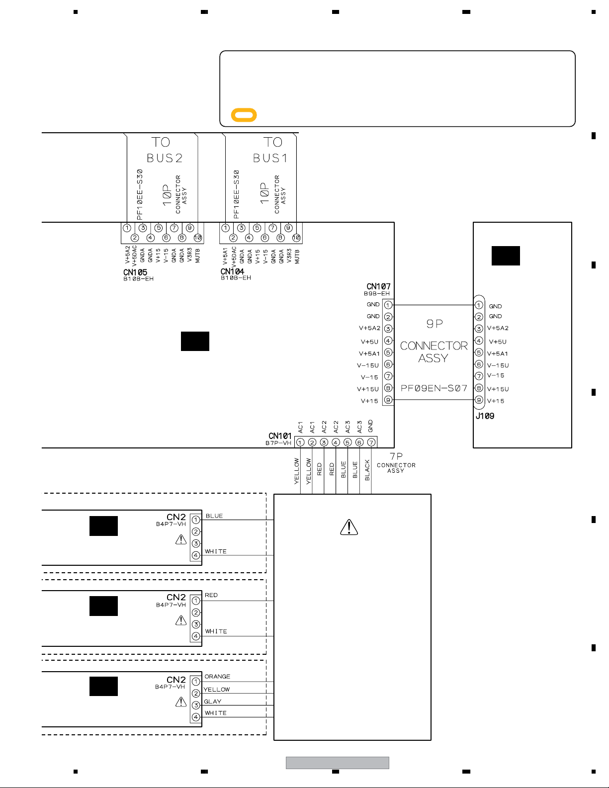
3.3 OVERALL WIRING DIAGRAM (2/2)
A
A
B
B
AC
REG1 ASSY
(DWR1385)
C
D
For
For
POWER CORD
: DDG1028
POWER CORD
: ADG7062
KUCXJ
E
WYXJ
AC INLET ASSY
: DKP3730
AC INLET ASSY
: DKP3731
For
RLTXJ
F
POWER CORD
: ADG7062
16
1234
AC INLET ASSY
: DKP3731
DJM-1000
5678
÷
When ordering service parts, be sure to refer to "EXPLODED VIEWS and PARTS
LIST" or "PCB PARTS LIST".
÷
The > mark found on some component parts indicates the importance of the safety
factor of the part. Therefore, when replacing, be sure to use parts of identical
designation.
÷
: The power supply is shown with the marked box.
A
B
AD
REG2 ASSY
(DWR1386)
AA
ACIN ASSY
(DWR1383)
AA
ACIN ASSY
(DWR1383)
AB
POWER ASSY
(DWR1384)
POWER
TRANSFORMER
KUCXJ : DTT1179
WYXJ : DTT1178
RLTXJ : DTT1180
C
D
E
AA
ACIN ASSY
(DWR1399)
56
DJM-1000
F
17
7
8
1234
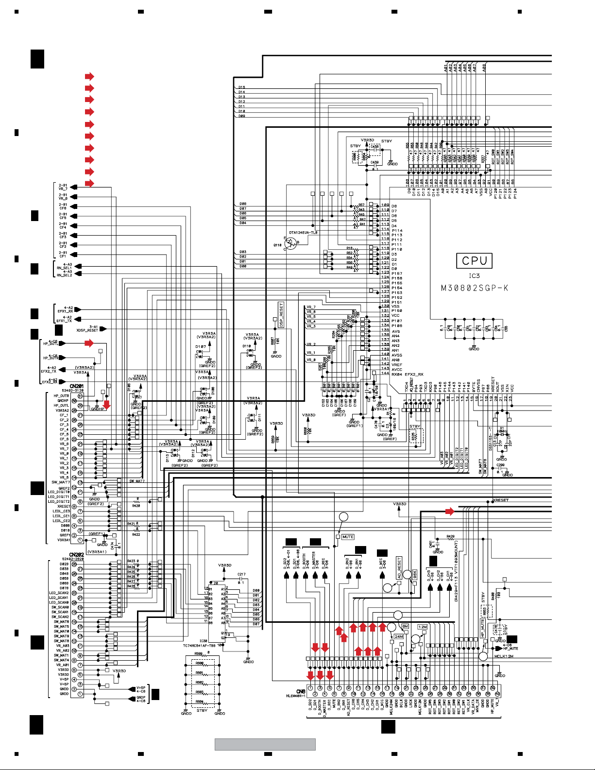
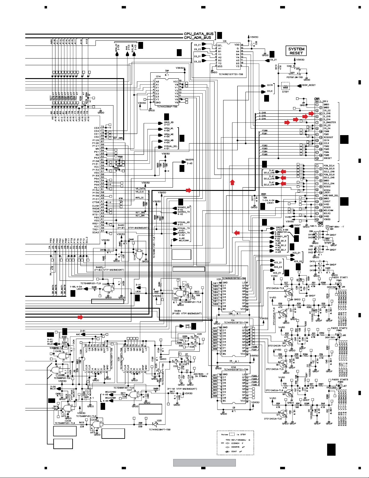
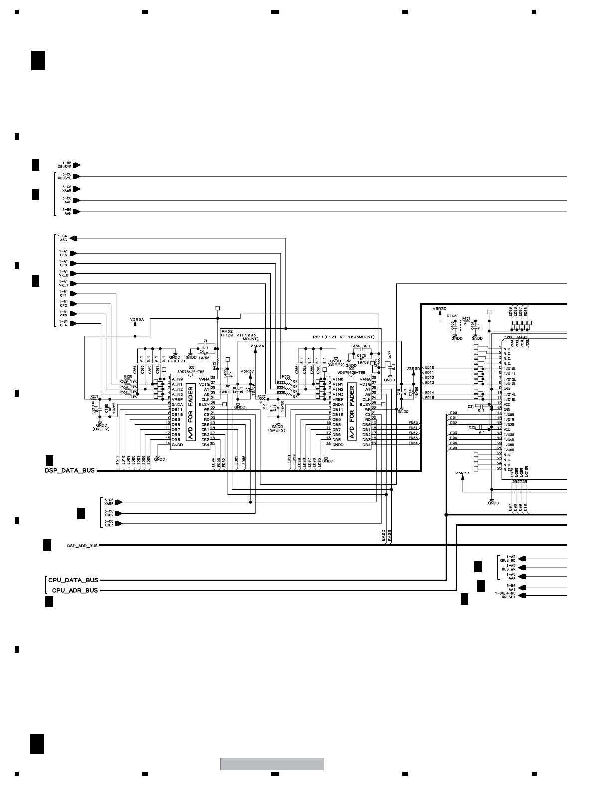
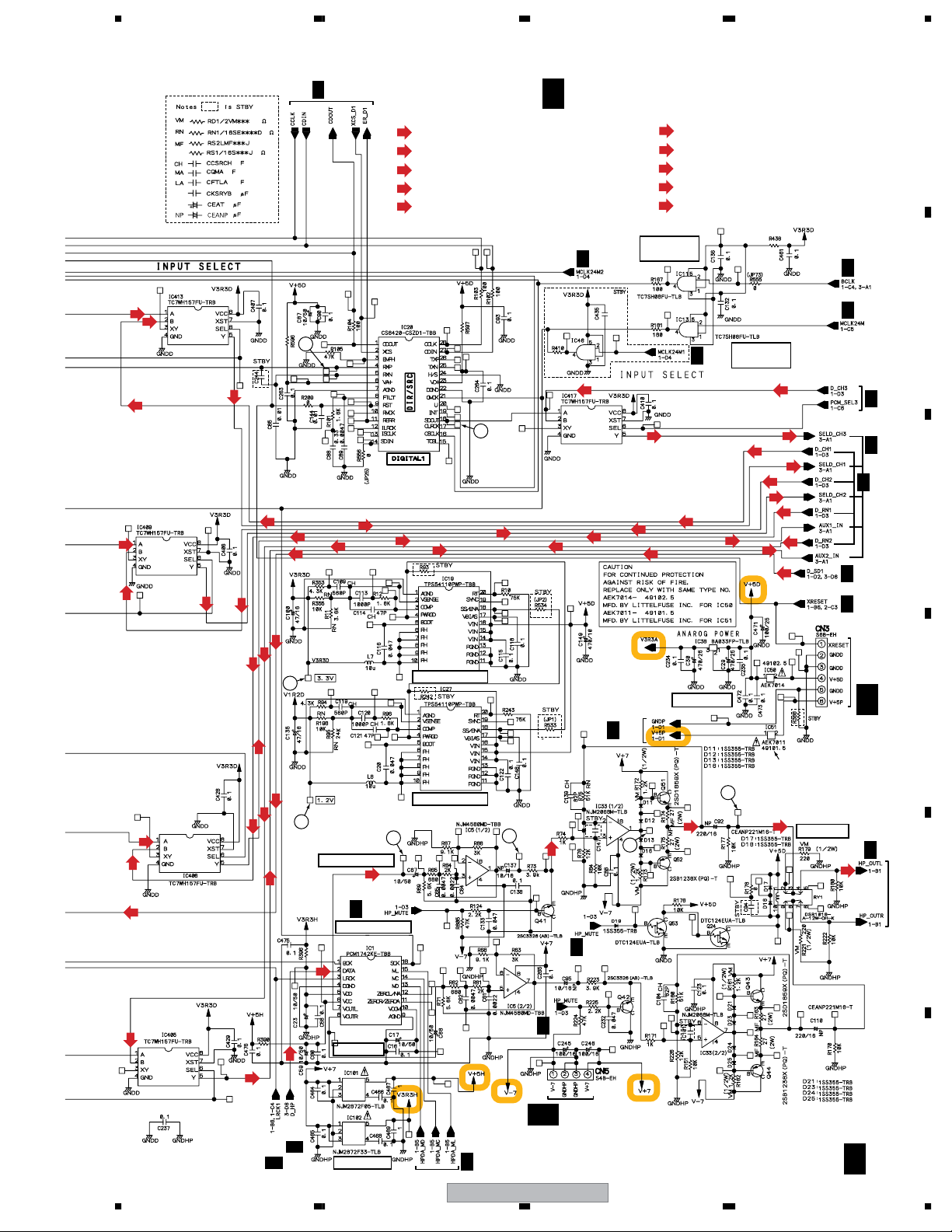
3.4 DIGITAL MAIN ASSY (1/4)
A
B
C
A 1/4
2/4A
A
4/4
4/4
A
A
4/4A
DIGITAL MAIN ASSY (DWG1586)
(CH*Y)
: AUDIO SIGNAL ROUTE (CH* Y ch)
(CH*D)
: AUDIO SIGNAL ROUTE (CH* Digital ch)
(RND)
: AUDIO SIGNAL ROUTE (Return Digital ch)
(SDD)
: AUDIO SIGNAL ROUTE (Send Digital ch)
(BOD)
: AUDIO SIGNAL ROUTE (Booth Digital ch)
(RECD)
: AUDIO SIGNAL ROUTE (Rec Digital ch)
(MAD)
: AUDIO SIGNAL ROUTE (Master Digital ch)
(MICD)
: AUDIO SIGNAL ROUTE (Mic Digital ch)
(HP)
: AUDIO SIGNAL ROUTE (Phones L ch)
(D)
: AUDIO SIGNAL ROUTE (Digital ch)
3/4
(HP)
D
E
CN4009
S
CN4501
P
(HP)
(CH4,5,6D)
4
3/4
3/4,4/4A
A
4/4
A
3/4
A
4/4A
6
7
2
(SDD)
(SDD)
(MAD)
(BOD)
(RND)
(RECD)
(RND)
(CH4D)
(CH6D)
(CH5D)
(CH3D)
(MICD)
(CH2D)
(CH1D)
1
3
5
4/4A
F
18
A 1/4
4/4A
CN507
N
DJM-1000
1234
5678
A
2/4
2/4A
A
4/4
2/4
A
4/4A
A
4/4
(CH6D)
(CH5D)
(CH4D)
(D)
A
B
CN701
A
(CH4,5,6D)
A
4/4A
2/4
4/4
(D)
3/4
A
4/4
A
(CH6Y)
(CH5Y)
(CH4Y)
K
CN702
C
K
3/4,4/4A
3/4A
A
(CH4,5,6D)
2/4A
4/4
LRCK BUFFER
(D)
4/4
A
3/4A
A
2/4,4/4A
CDOUT
BUFFER
LRCK BUFFER
A
3/4
A
3/4
2/4
4/4
A
4/4
A
D
E
MCLK12M
BUFFER
BCLK
BUFFER
4/4A
MCLK24M
BUFFER
56
MCLK24M
BUFFER
DJM-1000
F
A 1/4
19
7
8
1234
3.5 DIGITAL MAIN ASSY (2/4)
A
B
C
A 2/4
A
1/4
3/4A
1/4
A
DIGITAL MAIN ASSY
(DWG1586)
D
3/4A
A
3/4
3/4
A
1/4A
E
A
1/4
F
1/4,4/4
A
A
3/4
A 2/4
20
DJM-1000
1234
5678
A
B
FROM
FROM
C
1/4A
D
E
56
DJM-1000
F
A 2/4
21
7
8
1234
3.6 DIGITAL MAIN ASSY (3/4)
A
4/4A
1/4
A
4/4
A
A
1/4,4/4
A
B
1/4
A
(CH1Y)
(CH2Y)
(CH3Y)
(CH4Y)
(CH5Y)
(CH6Y)
(RNY)
(RNY)
1/4
(CH1Y)
(CH2Y)
(CH3Y)
(CH4Y)
(CH5Y)
(CH6Y)
(RNY)
(RNY)
(RNY)
(RNY)
(CH6Y)
(CH5Y)
(CH4Y)
(CH3Y)
(CH2Y)
(CH1Y)
C
D
A
1/4
E
(SDD)
(BOD)
(SDD)
(HPD)
F
(MAD)
(MICD)
(MICD)
(MAD)
(BOD)
(SDD)
(SDD)
(HPD)
A 3/4
22
DJM-1000
1234
5678
A 3/4
DIGITAL MAIN ASSY
(DWG1586)
2/4A
2/4A
A
B
C
(D)
(RECD)
(RECD)
(MICD)
(MAD)
(BOD)
(SDD)
(SDD)
(HPD)
DJM-1000
56
(CH*Y)
(RECD)
(MICD)
7
: AUDIO SIGNAL ROUTE (CH* Y ch)
(RNY)
: AUDIO SIGNAL ROUTE (Return Y ch)
(SDD)
: AUDIO SIGNAL ROUTE (Send Digital ch)
(BOD)
: AUDIO SIGNAL ROUTE (Booth Digital ch)
: AUDIO SIGNAL ROUTE (Rec Digital ch)
(MAD)
: AUDIO SIGNAL ROUTE (Master Digital ch)
: AUDIO SIGNAL ROUTE (Mic Digital ch)
(HPD)
: AUDIO SIGNAL ROUTE (Phones Digital ch)
(D)
: AUDIO SIGNAL ROUTE (Digital ch)
2/4A
(D)(D)
(RECD)
(MICD)
(MAD)
(BOD)
(SDD)
(SDD)
(HPD)
1/4A
1/4,4/4
A
4/4A
A
1/4
D
E
F
A 3/4
23
8
1234
3.7 DIGITAL MAIN ASSY (4/4)
A
18
20
(ERN)
19
1/4A
1/4A
(ERN)
(ESD)
B
18
20
(ERN)
(ESD)
11
(S)
(ERN)
19
(ESD)
18
C
(S)(S)
(S)
(S)
(ESD)
(S)
(ERN)
(ERN)
(ESD)
(ESD)
(S)
11
(S)
1/4A
(S)
(S)
12
1/4A
(S)
(S)
12
18
(ESD)
D
(ERN)
(S)
(S)
(S)
11
1/4A
(ESD)
E
F
24
CN801
L
UPDATE
CONNECTOR
A 4/4
(ERN)
12
10
A
1/4
A
1/4,3/4
1/4A
(ERN)
17
17
(SDD)
(ERN)
(SDD)
11
(SDD)
(ESD)
(SDD)
1/4A
(ESD)
12
(ERN)
DJM-1000
1234
5678
(S)
(CH1D)
(S)
(CH1D)
(CH1Y)
11
(RND)
(SDD)
1/4A
(CH1Y)
(CH*Y)
: AUDIO SIGNAL ROUTE (CH* Y ch)
(CH*D)
: AUDIO SIGNAL ROUTE (CH* Digital ch)
(ESD)
: AUDIO SIGNAL ROUTE (Effect Send L ch)
(ERN)
: AUDIO SIGNAL ROUTE (Effect Return L ch)
(S)
: AUDIO SIGNAL ROUTE (Sound L ch)
12
(RNY)
(RNY)
(CH2Y)
A 4/4
A
1/4
(CH3D)
(RND)(RND)
DIGITAL MAIN ASSY (DWG1586)
(HP)
: AUDIO SIGNAL ROUTE (Phones L ch)
(HPD)
: AUDIO SIGNAL ROUTE (Phones Digital ch)
(SDD)
: AUDIO SIGNAL ROUTE (Send Digital ch)
(RND)
: AUDIO SIGNAL ROUTE (Return Digital ch)
(RNY)
: AUDIO SIGNAL ROUTE (Return Y ch)
BCLK
(RND)
(CH3Y)
BUFFER
(CH2D)
(SDD)
MCLK24M
A
1/4
BUFFER
(CH3D)
(CH3Y)
(CH1D)
(CH1Y)
(CH2D)
(CH2Y)
(CH1D)(CH1D)
(RNY)
(RNY)
(RND)
(RND)
1/4,3/4
A
A
1/4
A
A
B
1/4A
3/4
1/4A
C
(CH2D)
(ERN)
(RND)
(SDD)
(CH2Y)
(CH2D)
(RND)(RND)
(RND)
(RNY)
(RND)
(RNY)
(SDD)(SDD)
9
8
PHONES AMP
(HPD)
13
(HP)
1/4
A
PHONES D/A
D/D FOR DSP
D/D FOR DSP
14
(HP)
(SDD)
1/4,3/4A
1/4,2/4
A
CN103
+3.3V REG
A
1/4
Serial No.
EAMP00001JP to 15JP (JJXJ) :
EAMP00001YY to 40YY (WYXJ) :
16
15
1/4
A
(HP)
EAMP00001LY to 20LY (RLTXJ) :
AEK7007 (491.750)
(HP)
HP MUTE
(HP)
AB
1/4A
D
E
(RND)
1/4
A
+5V REG
(RNY)
(HPD)
AB
CN102
3/4A
1/4
A
56
+3.3V REG
1/4
A
DJM-1000
F
A 4/4
25
7
8
1234
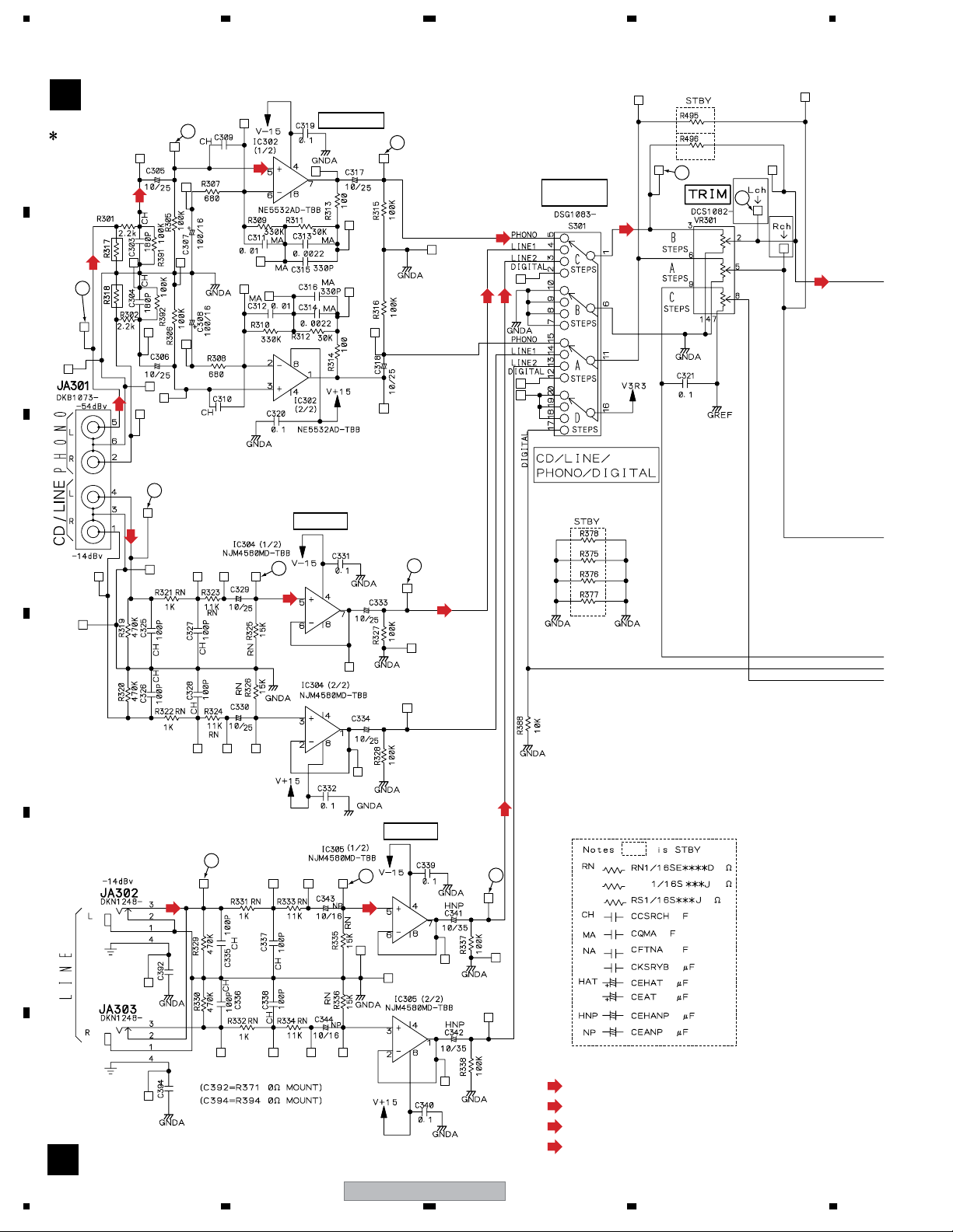
3.8 CH1/CH2 INPUT ASSY
CH1/CH2 INPUT ASSY
B
A
(DWX2405)
(R317= C347 220p MOUNT)
(R318= C348 220p MOUNT)
+
(PI)
RSK
2
330p
(PI)
RSK
RSK
PHONO EQ
RSK
RSK
3
+
(C305, C306, C317, C318
CCH1559– –TS)
(PI)
INPUT
SELECTOR
(CH1)
4
5
(PI)
(CH1)
1
B
RSK
RSK
RSK
+
(PI)
RSK
+
RSK
330p
(LI)
(LI)
15
C
(LI)
+
D
+
16
(LI)
BUFFER
17
+
(C329, C330, C333, C334
CCH1559– –TS)
+
(LI)
BUFFER
(LI)
18
19
(LI) (LI)
20
RSK
RSK
E
(LI)
: AUDIO SIGNAL ROUTE (Line input L ch)
(PI)
F
: AUDIO SIGNAL ROUTE (Phono input L ch)
(CH1)
: AUDIO SIGNAL ROUTE (CH1 L ch)
(CH1D)
: AUDIO SIGNAL ROUTE (CH1 Digital ch)
B
26
1234
DJM-1000
5678
(CH1)
(CH1)
(CH1)
7
A
(CH1)
6
9
8
(CH1)
B
(CH1)
C
MCLK12M
BUFFER
12
(CH1)
(CH1D)
13
11
(CH1)
(CH1D)
(CH1)
BCLK
BUFFER
DJM-1000
56
14
D
(CH1)
10
E
(CH1D)
CN505
N
N
CN506
F
B
27
7
8
1234
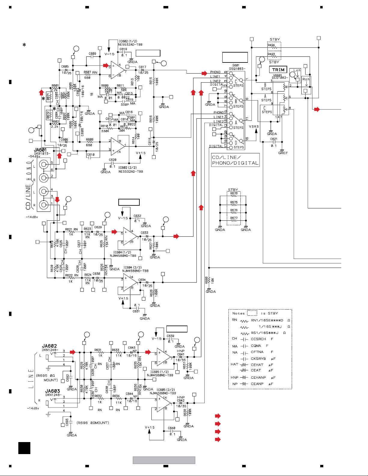
3.9 CH3/CH4 INPUT ASSY
A
(R671= C698 220p MOUNT)
(R672= C691 220p MOUNT)
RSK
(PI)
2
CH
330p
(PI)
RSK
RSK
PHONO EQ
RSK
3
(C605, C606, C617, C618
CCH1559– –TS)
(PI)
(LI)(LI)
INPUT
SELECTOR
4
5
(CH3)
B
1
C
RSK
(PI)
(LI)
RSK
330p
15
RSK
RSK
RSK
CH
(LI) (LI)
BUFFER
16
(LI)
+
17
+
(LI)
(C629, C630, C633, C634
CCH1559– –TS)
18
+
+
BUFFER
RSK
RSK
19
D
20
E
F
(LI)(LI)
(LI)
: AUDIO SIGNAL ROUTE (Line input L ch)
(PI)
: AUDIO SIGNAL ROUTE (Phono input L ch)
(CH3)
: AUDIO SIGNAL ROUTE (CH3 L ch)
(CH3D)
: AUDIO SIGNAL ROUTE (CH3 Digital ch)
28
C
DJM-1000
1234
5678
CH3/CH4 INPUT ASSY
C
(CH3)
7
(DWX2406)
9
(CH3)
(CH3)
A
(CH3)
6
8
(CH3)
B
(CH3)
C
MCLK12M
BUFFER
(CH3)(CH3)
10
(CH3D)
14
(CH3)
(CH3)
12
(CH3D)
13
BCLK
BUFFER
11
(CH3)
DJM-1000
56
(CH3)
(CH3D)
N
O
CN504
CN304
D
E
F
C
29
7
8
1234
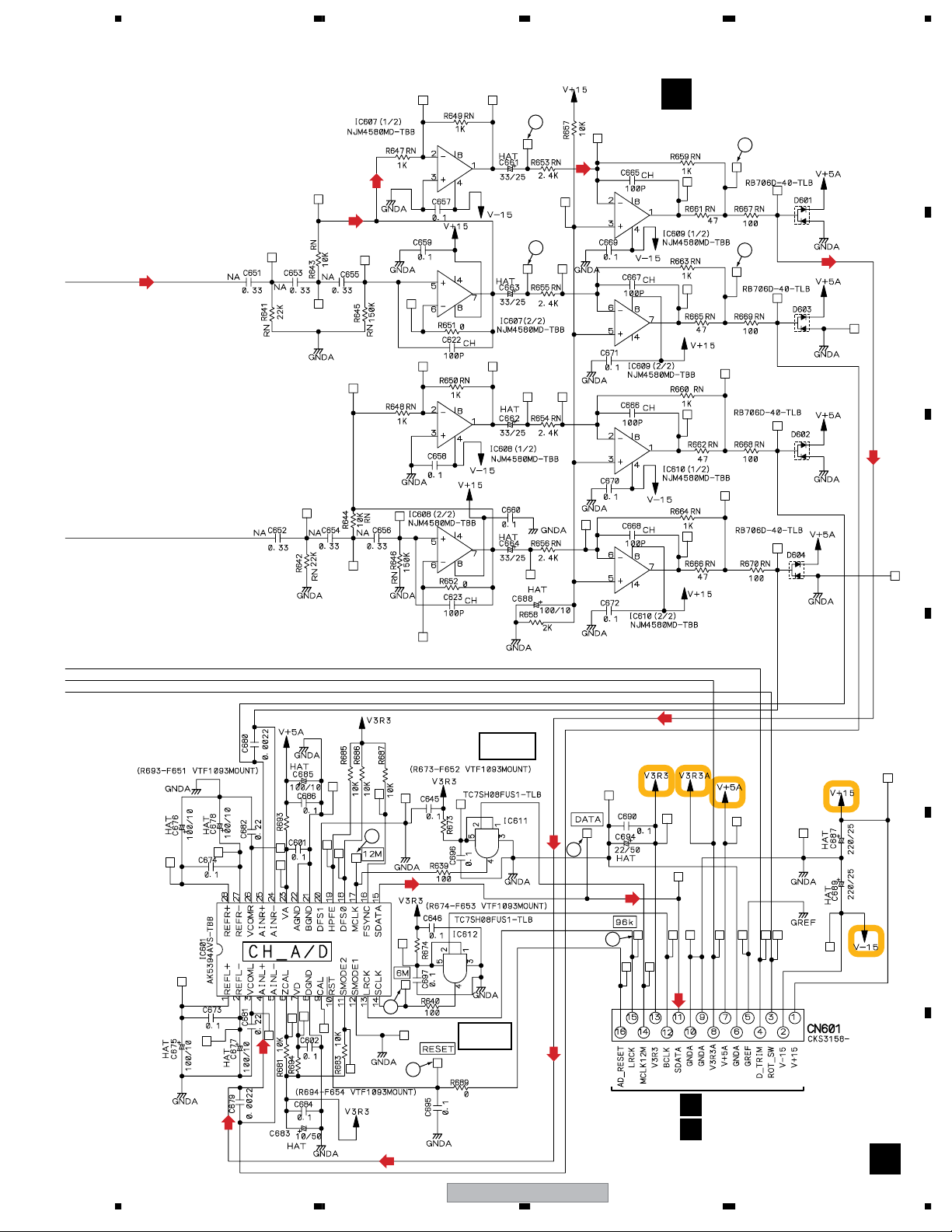
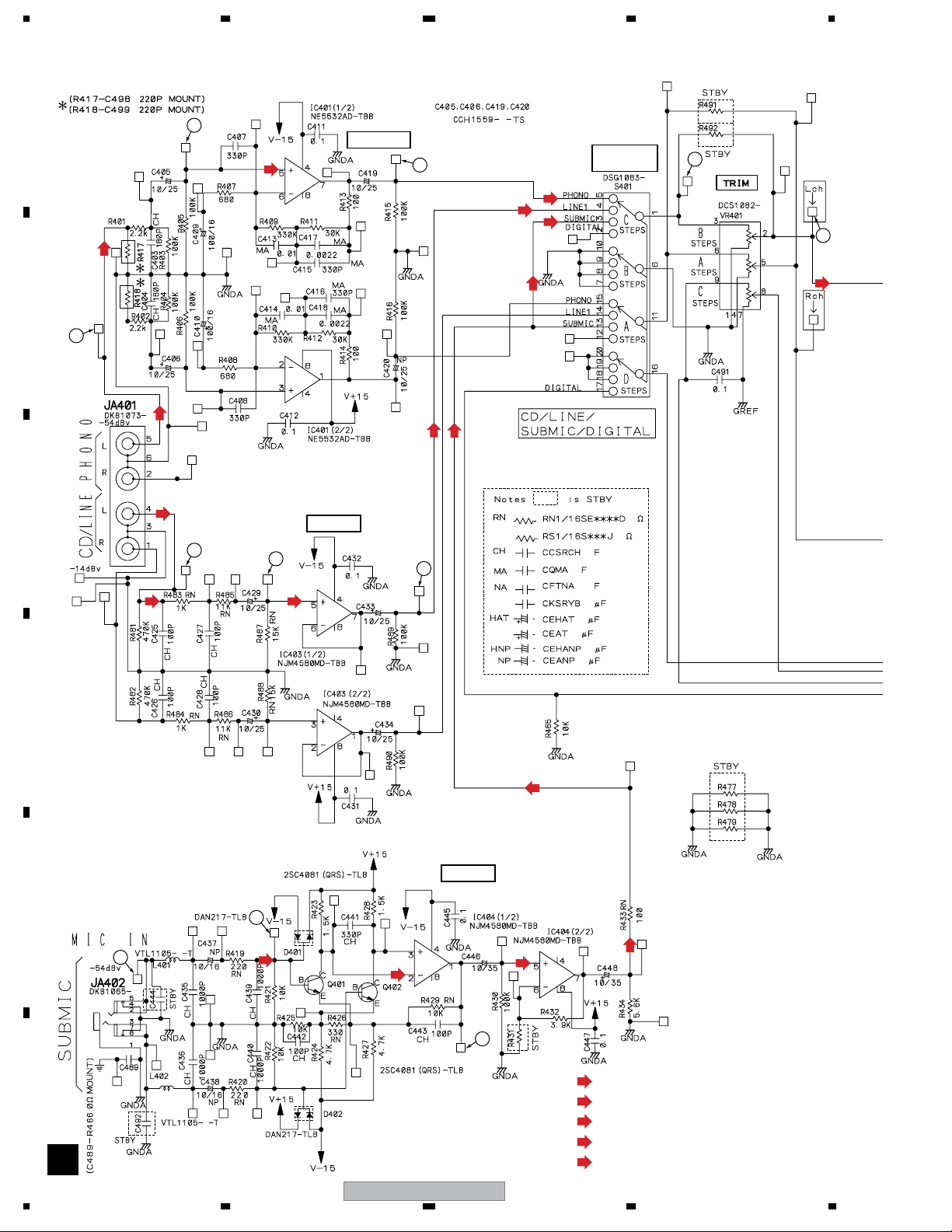
3.10 CH5/CH6 INPUT ASSY
A
2
(PI)
RSK
CH
(PI)
RSK
RSK
RSK
PHONO EQ
RSK
INPUT
3
(PI)
(LI)
(SM)
(SM)
SELECTOR
4
5
(CH5)
B
RSK
16
(LI)
RSK
BUFFER
RSK
17
(LI)
(SM)
1
C
RSK
(LI)
(PI)
RSK
CH
15
(LI)
D
(SM)
MIC AMP
E
18
19
(SM)
(SM)
HNP
(SM)
HNP
(SM)
20
RN
RN
F
D
30
DJM-1000
(LI)
: AUDIO SIGNAL ROUTE (Line input L ch)
(PI)
: AUDIO SIGNAL ROUTE (Phono input L ch)
(SM)
: AUDIO SIGNAL ROUTE (Sub Mic L ch)
(CH5)
: AUDIO SIGNAL ROUTE (CH5 L ch)
(CH5D)
: AUDIO SIGNAL ROUTE (CH5 Digital ch)
1234
 Loading...