

LG CT21Q92 ADJUSTMENT INSTRUCTIONS

- 9 -
¡ Safety Precautions
1. It is safe to adjust after using insulating transformer between
the power supply line and chassis input to prevent the risk of
electric shock and protect the instrument.
2. Never disconnect leads while the TV receiver is on.
3. Don't short any portion of circuits while power is on.
4. The adjustment must be done by the correct appliances.
5. Unless otherwise noted, set the line voltage to 230Vac¡
10%, 50Hz.
5. The adjustment of TVshould be performed after warming up
for 15 minutes.
¡ Test Equipment required
1. RF signal generator (with pattern generator)
2. DC Power Supply
3. Multimeter (volt meter)
4. Oscilloscope
5. Color analyzer
¡
PIF (Picture Intermediate Frequency) Adjustment
1) Connect the measuring equipment to the Main Board as
shown in Fig.1.
2) Set RF frequency and output level of RF SIGNAL
GENERATOR as shown Table 1.
3) Turn off S1 and S3 and on S2.
4) Adjust L104 so that the DC voltage may be 2.4¡ 0.1Vdc.
(Table 1)
¡ L’ VCO Adjustment (For SECAM-L’ MODEL)
1) Connect the measuring equipment to the Main Board as
shown in Fig.1.
2) Set RF frequency and output level of RF SIGNAL
GENERATOR as shown Table 1.
3) Turn on S1,S3 and off S2.
2) Adjust VR122 so that the DC Voltage may be 2.4¡ 0.1Vdc.
¡
RF AGC (Automatic Gain Control) Adjustment
1) Input PAL-B/G 05 CH.
2) Connect Multimeter to TP2(J15),AGC adjustment point.
3) Adjust VR120 until the voltage of Multimeter becomes
2.4¡ 0.1V.
¡ Screen Voltage Adjustment
1) Tune the RF Modulator to receive a PAL or SECAM signal.
2) Press MIX button on remote controller for Service to get into
the Screen Adjust Mode.
3) Adhere the Color Analyzer on the White window of CPT
face.
4) Adjust Screen Volume of FBT so that the luminance of White
window is 20¡ 1 FL.
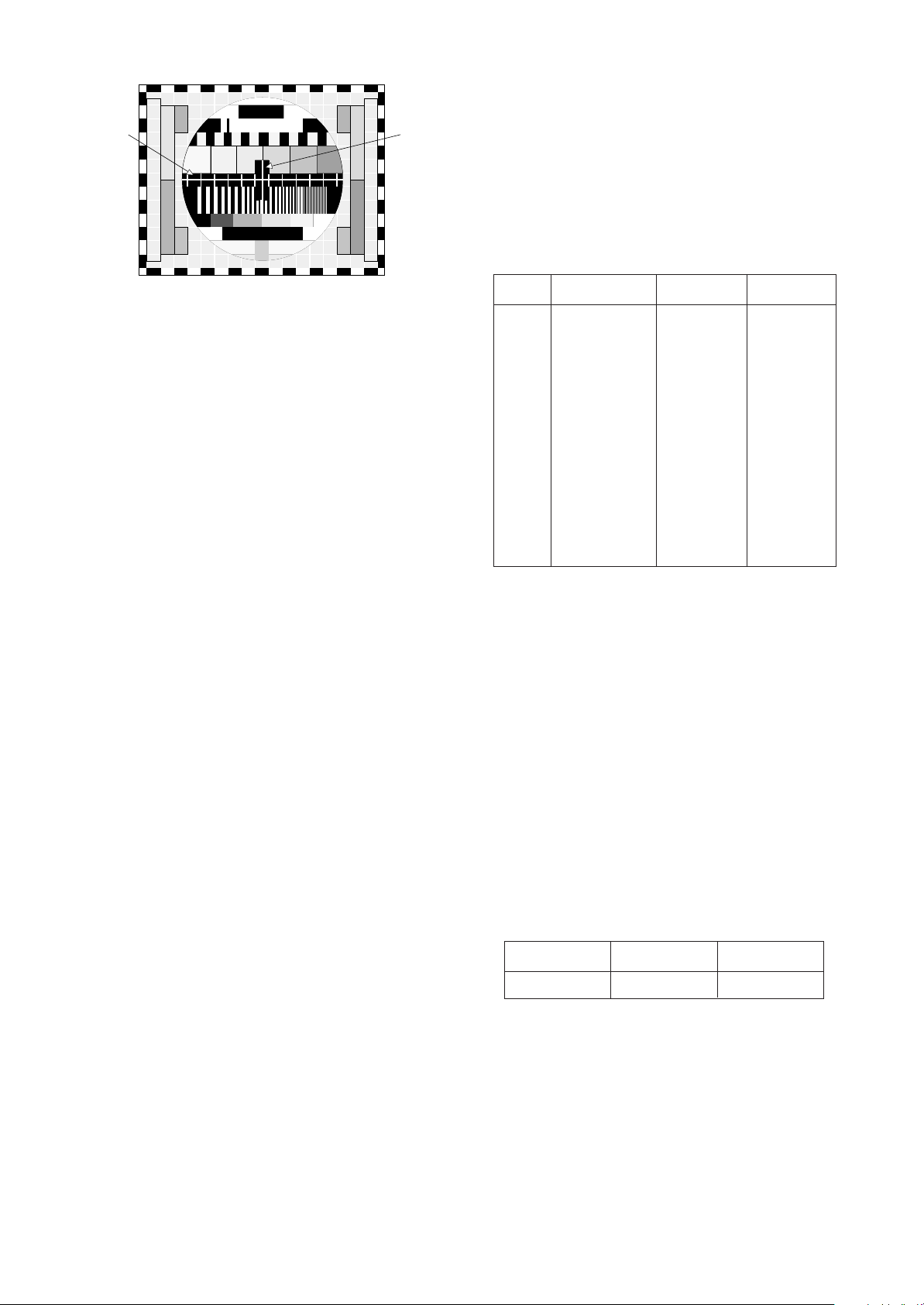
¡ Focus Adjustment
1) Tune the TV set to receive a digital pattern.
2) Adjust the upper Focus volume of FBT for the best focus of
vertical line B.
3) Adjust the lower Focus volume of FBT for the best focus of
area A.
4) Repeat above step 2) and 3) for the best overall focus.
IC101
TDA4470
TP1(VCO)
JP4(IF VCC)
24
7
13
14
1
0.01uF
JP1
L104
5V
PowerSupply
V Multimeter or Oscilloscope
JP3
38.9MHz
34.25MHz
(B/G,D/K,I,L)
(SECAM-L')
100 ohm
S1
4.7 Kohm
S3
S2
JP5
100 ohm
Q106
VR122
C139(+)
VR120
Test Point : TP1
Adjust : L104
Test Point : TP1
Adjust : VR122
Frequency
38.9MHz
34.25MHz
System
B/G,D/K/I,SECAM-L
SECAM-L’
Modulation
OFF
OFF
Output level
10mVp-p
10mVp-p
Adjust
L104
VR122
Fig. 1 : Connection Diagram of Equipment for PIF Adjustment
ADJUSTMENT INSTRUCTIONS
Test Point : TP 2(J15)
Adjust : VR120
Test Point : CPT Face
Adjust : Screen Control of FBT
Test Point : Observing Display
Adjust : Focus control of FBT
- 10 -
¡ Deflection Data Adjustment (Line SVC-2)
NOTE : How to enter into the Line Service Mode with a remocon.
1.Power off.
2.Press the Red button.
3.Press the Green button.
4.Press the Yellow button.
5.Press the Cyan button.
6.Press the OK button.
7.Power On.
1. Preparation for Deflection Adjustment
1) At SVC mode, press the Yellow colored buttonon the SVC
remocon.
And then,deflection data adjustment OSD(SVC2 mode) will
be displayed.
2) Press Channel UP/DOWN button for desirous function
Adjustment.
3) Press Volume UP/DOWN button to adjust the data.
4) Tune the TV set to receive a PAL B/G Digital pattern.
VL (Vertical Linearity)
Adjust so that the boundary line between upper and lower
half is in accord with geometric horizontal center of the CPT.
VA (Vertical Amplitude)
Adjust so that the circle of a digital circle pattern may be
located within the effective screen of the CPT.
SC (Vertical “S” Correction)
Adjust so that all distance between each horizontal lines
are to be the same.
VS (Vertical Shift)
Adjust so that the horizontal center line of a digital circle
pattern is in accord with geometric horizontal center of
the CPT.
HS (Horizontal Shift)
Adjust so that the vertical center line of a digital circle pattern
is in accord with geometric vertical center of the CPT.
EW (Horizontal Width)
Adjust to that a digital circle pattern looks like exact circle.
EP (East-west Parabolar)
Adjust so that middle portion of the outermost left and right
vertical line looks like parallel with vertical lines of the CPT.
EC (East-west Coner)
Adjust so that the vertical line at every 4 corners of the
screen looks like parallel with the vertical lines of the CPT.
ET (East-west Trapezium)
Adjust to make the length of top horizontal line same with
it of the bottom horizontal line.
(Table 2)
¡ White Balance Adjustment.(LINE SVC 1)
NOTE : This adjustment should be performed after screen
voltage adjustment.
1) Tune the TV set to receive an 100% white pattern.
2) Press the Yellow button on remote controller in the SVC
Mode.
3) Press PSM (RED) button on remote controller. (Standard
picture)
4) Press PR+ or PR- button for desirous function adjustment.
5) Adjust Low Light status of CR and CB with VOL+ or VOLat CG:50 until X=262
¡
8,Y=266¡8.
6) Adjust High Light status of RG and BG with VOL+ or VOLat CG:370 until X=262
¡
8,Y=266¡8.
7) Repeat above step 5) and 6) until each status of High Light
and Low Light.( for Europe:X=283
¡
8,Y=295¡8,Color
Temperature:9500k.)
b
A
B
Fig. 2
Menu
VS
VA
VL
SC
HS
EW
ET
EP
ES
EC
0600H~0900H
0050H~00CFH
0025H~00BFH
0000H~009FH
0000H~003FH
0400H~0EFFH
0700H~08FFH
06E0H~0840H
06A0H~0AFFH
0790H~08E0H
0748
00A3
0000
00D9
001D
09CF
0800
07C9
07BB
0820
Range 21” Flat
CPT
LG 21” FLAT
4.5
¡
1 FL
43
¡
1 FL
LOW LIGHT
HIGH LIGHT
 Loading...