

Page 1

Troubleshooting Guide
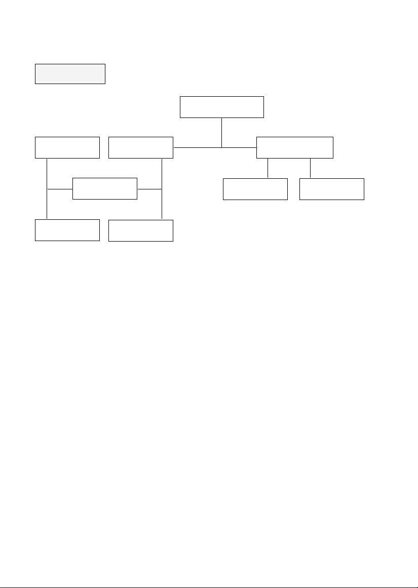
NO RASTER
Check +B voltage
at D825 Cathode.
Is the voltage at pin8 and
37 of IC501 8V?
Check pin40 of
IC501 (H-Out).
Check Q451
Collector waveform.
Check Q452
Collector waveform.
Check T401 &
each pin voltage.
Check
Fuse of AC line.
Check the voltage of
C808.
Check the voltage
at pin9 of IC801.
Check/replace
IC803, D824 and D835.
Check/replace
IC501.
Check/replace Q451,
T451 and R452.
Check/replace
Q452.
Check the in/output
of IC607.
Check the IIC Bus
Line (SDA,SCL) pin3
and 4 of IC501.
Check/replace
Fuse, D801 and
IC801.
Check/replace
R801 and D801.
Check D802,
D805, D807, Q801
and IC801.
Normal
Yes
Yes
Yes
Yes
No
No
No
No
OK
OK
254~380V
Lower than 6V
Open
0V
Abnormal
Page 2

NO SOUND
(PICTURE OK)
Select correct
system in MENU
Check L System
is right?
No
AM NO SOUND NICAM,FM NO SOUND
Abnor
mal
Not OK
Not
OK
Not
OK
Not OK
Not OK
Not OK
Not OK
No
Yes
Yes
Not OK
OK
OK
OK
OK
OK
OK
Normal
Normal
Normal
Check the logic of
pin3 and 15 of
IC101.
Check/replace
Z104 & +B of
IC101.
Check the AM
Line.
(pin27 of IC101)
Check AM Input of
IC601, pin44.
Check/replace
pin14 & 25 of
IC01.
Check Sound
system in MENU
OSD.
Select correct
system in MENU.
Check
pin47 of IC601.
Check X601 & pin16
and 46 of IC601, IIC
Bus Line.
Check/replace
X601 and IC601.
Check C607
& R601.
Check pin14
& 25 of IC01.
Check demodulated
SIF signal (pin26 of
IC101).
Check the logic of
pin3 and 15 of
IC101.
Check R, L input
of IC651, pin2 and
5.
Check +B of
IC651
& D822.
Is any OSD
displayed?
Check R,L Out
of IC601.
Check Z103,
Q102
& pin25 of IC101.
Page 3

NO PICTURE
NO SOUND
Is any OSD displayed?
Go to
NO RASTER (SOUND OK).
Go to
NO SOUND.
Check receiving system in
MENU & excute Auto-
programme.
Does the Auto-programme
operate properly?
Direct Input channel number
& store in manual-program
MENU.
And Check 5V, 12V, 33V &
IIC Bus Line of TUNER.
Is the CVBS signal
OK (pin 14 of IC101).
Check pin9 and 18 of
MICOM IC01.
Check IC01 &
H-Sync Line.
Check 5V, 12V,
33V
& IIC Bus Line.
Go to NO SOUND
PICTURE OK.
No
Yes
Not OK
Not OK
Not OK
Not OK
OK
OKOK
OK
OK
Yes
Page 4
NO RASTER
(SOUND OK)
OK OK
OK
OKOK
Not OK
Not OK
Not OKNot OK
Check the
Heater voltage of CPT(6-6.5Vrms).
Check
the HEATER pulse of FBT
T401.
Check
FR405,FR901 & P402.
Check
FBT T401.
Check
lk Current of IC501,pin18.
Check
HV,SCREEN voltage of
CPT.
Check
P501,ZD564 & IC501.
Check/replace
CPT Board components.
Check/replace
FBT T401.
Page 5

NO PICTURE
NO COLOR
Is the CVBS signal at pin14 of
IC101 normal?
Check Receiving system in
MENU & go to NO PICTURE,
NO SOUND.
Check the state of pin11 and 13
of IC201,L201 and R206(+B of
IC201).
Check/replace
Q201,L603(12V) & CVBS Line.
Check pin9 of IC501, IC702
IIC Bus Line & Q701.
Check IC502, L542
& pin26 of IC501.
Check X501, IC503, L541,
ZD541 & IC504(In case of
SECAM system).
Is the CVBS signal at pin16 of
IC201 normal?
Is the CVBS signal at pin 13 of
IC501 normal?
Is the CVBS signal at pin 2 of
IC702 normal?
Is the CVBS signal at pin11 of
IC501 normal?
Is the Y signal at pin 27 of
IC501 normal?
Check if R-Y and B-Y signal of
pin32 and 33 of IC501 are
normal?
Yes
Yes
Yes
Yes
Yes
Yes
No
No
No
No
No
No
No
Page 6

NO TELETEXT
Check the voltage of
pin7, 16 and 21 of IC701.
Check CVBS signal at pin2
of IC702 & X701.
Check IC701, 702 & IIC Bus
Line (SDA, SCL).
Check 5V & 12V Supply
Line of IC701 and 702.
And check pin803B & Power
Line (MAIN2 PCB).
Check/replace Q701, X701
& IC501.
OK
OK
OK
0V
Not OK
Page 7

ADJUSTMENT INSTRUCTIONS
YSafety Precautions
1. It is safe to adjust after using insulating transformer
between the power supply line and chassis input to
prevent the risk of electric shock and protect the
instrument.
2. Never disconnect leads while the TV receiver is on.
3. Don't short any portion of circuits while power is on.
4. The adjustment must be done by the correct appliances.
But this is changeable in view of productivity.
5. Unless otherwise noted, set the line voltage to
230Vac
!10%, 50Hz.
YTest Equipment required
1. RF signal generator (with pattern generator)
2. DC Power Supply
3. Multimeter (volt meter)
4. Oscilloscope
5. Color analyzer
T
PIF (Picture Intermediate Frequency) Adjustment
1) Connect the measuring equipment to the Main Board as
shown in Fig.1.
2) Set RF frequency and output level of RF SIGNAL
(Table 1)
T SECAM-L' Adjustment
NOTE : This adjustment should be performed after PIF
adjustment.
1) Turn on S1 and S3 and off S2.
2) Adjust VR101 so that the DC voltage may be indicated
3.1
!0.1Vdc.
IC01
TP1
JP7 IC05
IC102
5V
JP3
S1
S3
S2
JP5
JP6
Q106
4.7k½
100½
100½
24
6
10
15
VR101
1
103pF
Signal-
Generator
JP1
L107
16
VR102
38.9MHz
33.9MHz
5V
Power-
Supply
8V
V Multimeter or Oscilloscope
JP2
JP4
Test Point : TP1
Adjust : L107
Test Point : TP1
Adjust : VR102
Frequency
38.9MHz
33.9MHz
System
B/G/SECAM-L
SECAM-L'
Modulation
OFF
OFF
Output level
10mVp-p
10mVp-p
Adjust
L107
VR102
Main Board(Component side view)
Fig. 1 : Connection Diagram of Equipment for PIF Adjustment
Page 8

T
Vertical/Horizontal/E-W (East-West)
Adjustment (LINE SVC 1)
Adjustment Procedures
1) Tune the TV set to receive a digital circle pattern unless
otherwise noted.
2) Press OK button on Control Board continuously and OK
button on remote controller then you can find On Screen
Display. (Refer to the following Fig.3).
3) Press PR+ or PR- button for desirous function adjustment.
4) Press VOL+ or VOL- button for correct picture.
5) Press OK button to memorize all the adjusted data.
6) After finishing adjustment, press TV/AV button on remote
controller then TV is changed from SVC mode to normal
mode.
Fig. 3
VL--(Vertical Linearity)
Adjust so that the boundary line between upper and lower half is
in accord with geometric horizontal center of the CPT.
VH--(Vertical Height)
Adjust so that the circle of a digital circle pattern may be located
within the effective screen of the CPT.
SC--(Vertical "S" correction)
Adjust so that all distance between each horizontal lines are to
be the same.
VS--(Vertical Shift)
Adjust so that the horizontal center line of a digital circle pattern
is in accord with geometric horizontal center of the CPT.
EW--(Horizontal Width)
Adjust to that a digital circle pattern looks like exact circle.
EP--(East-west Parabola)
Adjust so that middle portion of the outermost left and right
vertical line looks like parallel with vertical lines of the CPT.
EC--(East-west Corner)
Adjust so that the vertical line at every 4 corners of the screen
looks like parallel with the vertical lines of the CPT.
ET--(East-west Trapezium)
Adjust to make the length of top horizontal line same with it of the
bottom horizontal line.
T White Balance Adjustment.(LINE SVC 2)
NOTE : This adjustment should be performed after screen
voltage adjustment.
1) Tune the TV set to receive an 100% white pattern.
2) Press Number 2 button on remote controller in the SVC
Mode (press OK button on control board continuously and
OK button on remote controller) then you can find On
Screen Display. (Refer to the following Fig.4).
3) Press PSM (RED) button on remote controller. (Standard
picture)
4) Press PR+ or PR- button for desirous function adjustment.
5) Adjust VOL+ or VOL- button for Gg31.
6)
Adjust VOL+ or VOL-button in each status of "Rg--"/"Bg--" for
X=288
!
8, Y=295!8 with color analyzer (color temperature
9000
cK).
NOTE : These adjustments are already aligned at the
time of manufacture for optimum
performance. Readjustment of them should
not be necessary unless IC02 (EEPROM) is
defective. Because all the information of these
adjustment are memorized in that IC.
[LINE SVC1] 1
CH5
VL 31 EW 40
VH 42 EP 44
SC 31 EC 31
VS 33 ET 31
HS 20 50HZ*
*: This is only displayed according to
receiving system.
PAL/SECAM System : 50Hz
NTSC System : 60Hz
[
Page 9

T
RF AGC (Automatic Gain Control) Adjustment
The RF AGC control (VR101) was aligned at the time of
manufacture for optimum performance over a wide range
conditions. Readjustment of VR101 should not be necessary
unless unusual local conditions exist, such as ;
1) Channel interference in a CATV system.
2) Picture bending and/or color beats, which are unusually
due to excessive RF signal input when the receiver is too
close to a transmitting tower or when the receiver is
connected to an antenna distribution system where the RF
signal has been amplified. In this case, the input signal
should be attenuated (with pad or filter) to a satisfactory
level.
3) Picture noise caused by "broadcast noise" or weak signal.
If the broadcast is "clean" and the RF signal is at least
1mV (60dBu), the picture will be noise free in any area.
Adjusting the VR101(RF AGC) control to one end of rotation
will usually cause a relatively poor signal to noise ratio;
Adjusting to the other end of rotation will usually cause a
degradation of over load capabilities resulting in color beats or
adjacent channel interference. For best results, adjust the
VR101 control while performing on all over local channels, or
the voltage at TP2 will be 6.5
!0.1Vdc in RF level 60!1dBuV.
T Screen Voltage Adjustment
1) Tune the TV set to receive a digital pattern.
2) Press PSM (RED) button on remote controller. (standard
picture)
3) Connect the probe of oscilloscope to the RK (Red
Cathode) of CPT Board.
4) Adjust Screen Volume of FBT so that the waveform is the
same as below Fig. 6.
T Focus Adjustment
NOTE: This adjustment should be performed after warming
up for 10 minutes.
1) Tune the TV set to receive an inactive channel station.
2) Adjust the Focus control of FBT for best overall focus.
Test Point : TP2 (J8) or Observing Display
Adjust : VR101
Test Point : RK (Red Cathode of CPT Board)
Adjust : Screen Control of FBT
Test Point : Observing Display
Adjust : Focus control of FBT
Horizontal
FlyBack Time
Black level
White level
170Vp-p
Page 10

541
530
521
400
943
520
501
542
540
102
913
150
510
112
170
120
300
121
310
320
330
315
CF25A64DF EXPLODED VIEW
- 1 -
102 341-919A HOLDER,D-COIL
112 112-C28F(NE) CPT A66EAK071*01 28Ó
112-C25H(NE) CPT A59EAK071*11 25Ó
120 120-D38B SPEAKER,F/RANGE 10W/20W 8OHM 28Ó
120-C77F SPEAKER 8OHM 5W 25Ó
121 120-C76E SPEAKER,TWEETER 8OHM 74*D50*28 28Ó
120-C76A SPEAKER,TWEETER 25Ó
150 150-D05D COIL,DEGAUSSING,CU 28Ó 60T 8.7OHM
150-D05N COIL,DEGAUSSING,CU 25Ó 70T 15OHM
170 170-586Y LEAD SET,CPT EARTH FOR 29INCH
170-844B LEAD SET,CPT EARTH FOR 25INCH
300 3091V00050J CABINET ASSY SCF28A64T PPLRI7
3091V00069B CABINET ASSY SCF25A64T PPLRI7
3091V00069C CABINET ASSY(NE-UK) 25Ó
3091V00069D CABINET ASSY(NE-FS) 25Ó
310 441-455A BUTTON,CONTROL
315 3581V00006A DOOR ASSY 28Ó
3581V00012A DOOR ASSY 25Ó
320 320-062F SPRING,KNOB
330 5020V00065A BUTTON,POWER 28Ó
5020V00142A BUTTON,POWER 25Ó
400 3809V00036D BACK COVER ASSY 28Ó
303-M23B BACK COVER ASSY 25Ó
303-M23D BACK COVER ASSY(NE-UK) 25Ó
501 312-398C FRAME,MAIN
510 109-A05E PWB ASSY,CPT 73A 28ÓDARK M-IN
520 6871VMM056D PWB ASSY,MAIN1 (73A) 28Ó
6871VMM056H PWB ASSY,MAIN1 (73A) 25Ó-NOR(W/O-D,L)
6871VMM056J PWB ASSY,MAIN1 (73A) 25Ó-NOR(W/O-L)
6871VMM056K PWB ASSY,MAIN1 (73A) 25Ó-NOR(W/ L)
521 3501V00002C BOARD ASSY (PC-73A,CF-28A64T)
3501V00002B BOARD ASSY (PC-73A,CF-28A60)
530 6871VDM039B PWB ASSY,MAIN2 (73A)28Ó
6871VDM039D PWB ASSY,MAIN2 (73A)25Ó
540 6871VSM082A PWB ASSY,CONTROL
541 174-322E CORD,POWER W/FILTER L=400(179B)
542 341-783A HOLDER,LED
913 332-229D SCREW ASSY,HEXAGON HEAD (D7,L28)
943 1PPF0403116 SCREW,PAN HEAD D4 L16
NO.
PART NO.
DESCRIPTION
Page 11

CF25A64DF REPLACEMENT PARTS LIST
- 15 -
The components identified by shading and
mark are critical for safety.
Replace only with part number specified.
LOCA. NO PART NO DESCRIPTION
D701
D801
D802
D803
D805
D807
D808
D822
D824
D825
D829
D831
D832
D833
D835
D851
D852
D853
D854
D855
D856
D857
D921
D924
D941
D944
D961
D964
D965
ZD103
ZD358
ZD359
ZD360
ZD361
ZD408
ZD501
ZD502
ZD541
ZD561
ZD562
ZD563
ZD564
ZD801
ZD808
Q01
Q02
Q03
Q104
Q105
Q11
Q201
0DD414809ED
0DD560000AA
0DD150009CA
0DD100009AL
0DD060009AC
0DD060009AC
0DD060009AC
0DD420000BB
0DD060009AC
0DD410000AD
0DD420000BB
0DD414809ED
0DD414809ED
0DD414809ED
0DD150009CA
0DD060009AC
0DD060009AC
0DD060009AC
0DD060009AC
0DD414809ED
0DD400309AD
0DD414809ED
0DD247109AA
0DD247109AA
0DD247109AA
0DD247109AA
0DD247109AA
0DD247109AA
0DD400309AD
0DZ330009BA
0DZ240009BB
0DZ240009BB
0DZ330009CA
0DZ510009AB
0DZ820009DA
0DZ240009BC
0DZ750009AA
0DZ510009AB
0DZ510009AB
0DZ510009AB
0DZ510009AB
0DZ750009AA
0DZ750009AA
0DZ750009AA
0TR319809AA
0TR102009AB
0TR319809AA
0TR319809AA
0TR319809AA
0TR126609AA
0TR319809AA
DIODE DS4148
DIODE D5SB60 BRIDGE (5A/600V)S.D.G
DIODE RGP15J
DIODE EH-1ZV
DIODE TVR06J 0.6A/600V 250NS
DIODE TVR06J 0.6A/600V 250NS
DIODE TVR06J 0.6A/600V 250NS
DIODE D4L20U
DIODE TVR06J 0.6A/600V 250NS
DIODE RU4AM,LF-L1
DIODE D4L20U
DIODE DS4148
DIODE DS4148
DIODE DS4148
DIODE RGP15J
DIODE TVR06J 0.6A/600V 250NS
DIODE TVR06J 0.6A/600V 250NS
DIODE TVR06J 0.6A/600V 250NS
DIODE TVR06J 0.6A/600V 250NS
DIODE DS4148
DIODE IN4003A RECT
DIODE DS4148
DIODE 1S2471
DIODE 1S2471
DIODE 1S2471
DIODE 1S2471
DIODE 1S2471
DIODE 1S2471
DIODE IN4003A RECT
DIODE ZENER HZT33
DIODE ZENER MTZ24B
DIODE ZENER MTZ24B
DIODE ZENER MTZ 33B
DIODE ZENER MTZ5.1B
DIODE,ZENER MTZ8.2C 0.5W(52MM)TP
DIODE ZENER MTZ2.4B 2.4V K-ROHM
DIODE ZENER MTZ7.5B
DIODE ZENER MTZ5.1B
DIODE ZENER MTZ5.1B
DIODE ZENER MTZ5.1B
DIODE ZENER MTZ5.1B
DIODE ZENER MTZ7.5B
DIODE ZENER MTZ7.5B
DIODE ZENER MTZ7.5B
TR,KTC3198-TP-Y (KTC1815)
TR,KRC102M,TP(KRC1202)
TR,KTC3198-TP-Y (KTC1815)
TR,KTC3198-TP-Y
TR,KTC3198-TP-Y
TR,KTA1266-TP-Y (KTA1015)
TR,KTC3198-TP-Y (KTC1815)
LOCA. NO PART NO DESCRIPTION
IC01
IC02
IC03
IC101
IC102
IC1651
IC201
IC351
IC501
IC502
IC503
IC504
IC505
IC601
IC602
IC605
IC606
IC607
IC701
IC702
IC801
IC802
IC803
IC805
IC806
IC851
D04
D05
D06
D07
D08
D09
D101
D102
D104
D105
D106
D107
D109
D261
D401
D402
D404
D451
D452
D453
D454
D501
D531
0ISO861809A
0ISG241600A
0IKE703300B
0ITF447400A
0ISH052100A
0ISA428200A
0IGS381200A
0IPH835050A
0IPH837600A
0IPH456620A
0IPH466500B
0IPH839520A
0IMA586000A
0IIT341000E
0IIT351900A
0ISG282200A
0IKE703300B
0IKE780800A
0ITI724160A
0ITI702062A
0ISK670900A
0ISH123200B
0ISK140000A
0ISH052100A
0ISH122100A
0ISH052100A
0DD414809ED
0DD414809ED
0DD414809ED
0DD414809ED
0DD414809ED
0DD414809ED
0DD414809ED
0DD414809ED
0DD414809ED
0DD859009AA
0DD859009AA
0DD414809ED
0DD414809ED
0DD000000BA
0DD060009AC
0DD200009AH
0DD060009AC
0DD410000AC
0DD410000AB
0DD150009CA
0DD400309AD
0DD414809ED
0DD414809ED
IC,LG8618-09A(CXP86441-501S)52SD,
IC,ST24C16 8D EEPROM(16K)
IC,KIA7033P 3P 3.3V RESET(TAPING)
IC,TDA4474(VIF)
IC,PQ05RF21 4P(TO-220) 5V S/W REG
IC,LA4282
IC,GL3812(HA11518)
IC,TDA8350Q/N5 13P,SIP BK V/DEF+E
IC,TDA8376-N1 52SD MULTI VIDEO P.
IC,TDA4566/V2 18D CTI
IC,TDA4665-V4 16D 1H D/L(TAIWAN)
IC,TDA8395P/N2 16D SECAM DECODER
IC,AN5860 14D ANALOG RGB S/W
IC,MSP3410D 52P,SDIP BK MULTI SOU
IC,DPL3519A(DOLBY PRO LOGIC)
IC,TDA2822M 8D DUAL AUDIO AMP(1W)
IC,KIA7033P 3P 3.3V RESET(TAPING)
IC,KIA7808PI 3P(TO-220IS) 1A,8V
IC,CF72416N 20D TXT D/SLICER(VPS)
IC,CX70206NW 28DIP TXT DECORDER
IC,STR/S6709 9S SMPS-CNTR
IC,PC123 FY2PHOTO COUPLER
IC,SE140N 3P 130V ERROR AMP
IC,PQ05RF21 4P(TO-220) 5V S/W REG
IC,PQ12RF21 4P(TO-220) 12V S/W RE
IC,PQ05RF21 4P(TO-220) 5V S/W REG
DIODE DS4148
DIODE DS4148
DIODE DS4148
DIODE DS4148
DIODE DS4148
DIODE DS4148
DIODE DS4148
DIODE DS4148
DIODE DS4148
DIODE SILICON MA859
DIODE SILICON MA859
DIODE DS4148
DIODE DS4148
DIODE LAMP(DIFFUSION TYPE)
DIODE TVR06J 0.6A/600V 250NS
DIODE RU2AMV
DIODE TVR06J 0.6A/600V 250NS
DIODE RU4DS,LF-L1
DIODE RU4C,LF-L1
DIODE RGP15J
DIODE IN4003A RECT
DIODE DS4148
DIODE DS4148
ICs
DIODES
TRANSISTORS
Page 12

- 16 -
The components identified by shading and
mark are critical for safety.
Replace only with part number specified.
LOCA. NO PART NO DESCRIPTION
Q203
Q204
Q281
Q351
Q451
Q452
Q531
Q601
Q602
Q603
Q604
Q605
Q606
Q607
Q608
Q701
Q702
Q703
Q801
Q852
Q853
Q854
Q901
Q921
Q922
Q923
Q924
Q925
Q941
Q942
Q943
Q944
Q945
Q961
Q962
Q963
Q964
Q965
C09
C10
C102
C103
C105
C108
C110
C113
C114
C118
C119
C122
0TR126609AA
0TR319809AA
0TR126609AA
0TR988000AC
0TR223800AA
0TR270800AA
0TR126609AA
0TR126609AA
0TR126609AA
0TR126609AA
0TR126609AA
0TR126609AA
0TR126609AA
0TR126609AA
0TR126609AA
0TR319809AA
0TR319809AA
0TR126609AA
0TR385200AA
0TR322709AA
0TR322709AA
0TR319809AA
0TR126609AA
0TR319809AA
0TR322900AA
0TR319809AA
0TR422009CB
0TR421009CB
0TR319809AA
0TR322900AA
0TR319809AA
0TR422009CB
0TR421009CB
0TR319809AA
0TR322900AA
0TR319809AA
0TR422009CB
0TR421009CB
0CE106DF618
0CE335DK618
0CE476DF618
0CE106DK618
0CE107DF618
0CE476DF618
0CE476DF618
0CE106DF618
0CQ1052K439
0CE225DK618
0CQ4742K439
0CE226DF618
TR,KTA1266-TP-Y (KTA1015)
TR,KTC3198-TP-Y (KTC1815)
TR,KTA1266-TP-Y (KTA1015)
TR,KTB988-Y,W/A(KTB834)
TR,KTC2238A-Y
TR,BU2708AF BK
TR,KTA1266-TP-Y (KTA1015)
TR,KTA1266-TP-Y (KTA1015)
TR,KTA1266-TP-Y (KTA1015)
TR,KTA1266-TP-Y (KTA1015)
TR,KTA1266-TP-Y (KTA1015)
TR,KTA1266-TP-Y (KTA1015)
TR,KTA1266-TP-Y (KTA1015)
TR,KTA1266-TP-Y (KTA1015)
TR,KTA1266-TP-Y (KTA1015)
TR,KTC3198-TP-Y (KTC1815)
TR,KTC3198-TP-Y (KTC1815)
TR,KTA1266-TP-Y (KTA1015)
TR,2SC3852A
TR,KTC3227-Y,TP(KTC1627A)
TR,KTC3227-Y,TP(KTC1627A)
TR,KTC3198-TP-Y (KTC1815)
TR,KTA1266-TP-Y (KTA1015)
TR,KTC3198-TP-Y (KTC1815)
TR,KTC3229 (KTC2068)
TR,KTC3198-TP-Y (KTC1815)
TR,BF422L(AMMO)TO-92
TR,BF421L(AMMO)TO-92
TR,KTC3198-TP-Y (KTC1815)
TR,KTC3229 (KTC2068)
TR,KTC3198-TP-Y (KTC1815)
TR,BF422L(AMMO)TO-92
TR,BF421L(AMMO)TO-92
TR,KTC3198-TP-Y (KTC1815)
TR,KTC3229 (KTC2068)
TR,KTC3198-TP-Y (KTC1815)
TR,BF422L(AMMO)TO-92
TR,BF421L(AMMO)TO-92
C,ELECTROLYTIC 10UF STD 16V M
C,ELECTROLYTIC 3.3UF STD 50V M
C,ELECTROLYTIC 47UF STD 16V M
C,ELECTROLYTIC 10UF STD 50V M
C,ELECTROLYTIC 100UF STD 16V M
C,ELECTROLYTIC 47UF STD 16V M
C,ELECTROLYTIC 47UF STD 16V M
C,ELECTROLYTIC 10UF STD 16V M
C,POLYESTER(MYLAR) 1UF S 50V J
C,ELECTROLYTIC 2.2UF STD 50V M
C,POLYESTER(MYLAR) 0.47UF S 50V J
C,ELECTROLYTIC 22UF STD 16V M
LOCA. NO PART NO DESCRIPTION
C123
C125
C130
C136
C137
C139
C140
C15
C16
C1615
C1616
C1617
C1619
C1620
C1622
C1624
C1626
C1653
C1658
C1659
C1660
C1661
C1662
C1663
C1664
C1665
C1666
C1667
C1668
C1669
C1670
C1671
C172
C20
C201
C203
C205
C206
C211
C212
C214
C215
C216
C217
C218
C219
C22
C220
C23
C230
C231
C232
0CE475DK618
0CN3320F569
0CE106DF618
0CN1030F679
0CN1030F679
0CE227DF618
0CE477DF618
0CE107DF618
0CE227DF618
0CE227DF618
0CE227DF618
0CE227DF618
0CN4710K519
0CE227DF618
0CN4710K519
0CN4710K519
0CN4710K519
0CQ2221N509
0CE2256K618
0CQ1041N509
0CE108DJ618
0CE107DH618
0CE107DH618
0CK1030K945
0CE108DJ618
0CE228DJ650
0CE2256K618
181-442Z
0CQ2221N509
181-091B
0CE107DH618
0CE106DF618
0CE108DD618
0CE476DF618
0CE106DF618
0CE107DF618
0CE106DF618
0CE106DF618
0CE106DF618
0CE476DF618
0CE107DF618
0CQ3342K439
0CQ3342K439
0CQ3342K439
0CQ3342K439
0CQ3342K439
0CC1500K415
0CQ3342K439
0CC1500K415
0CN1030F679
0CE106DF618
0CE227DF618
C,ELECTROLYTIC 4.7UF STD 50V M
C,TUBULA 3300P 16V K
C,ELECTROLYTIC 10UF STD 16V M
C,TUBULA(HIGH DIELE) 0.01MF 16V M
C,TUBULA(HIGH DIELE) 0.01MF 16V M
C,ELECTROLYTIC 220UF STD 16V M
C,ELECTROLYTIC 470UF STD 16V M
C,ELECTROLYTIC 100UF STD 16V M
C,ELECTROLYTIC 220UF STD 16V M
C,ELECTROLYTIC 220UF STD 16V M
C,ELECTROLYTIC 220UF STD 16V M
C,ELECTROLYTIC 220UF STD 16V M
C,TUBULA(HIGH DIELE) 470PF 50V K
C,ELECTROLYTIC 220UF STD 16V M
C,TUBULA(HIGH DIELE) 470PF 50V K
C,TUBULA(HIGH DIELE) 470PF 50V K
C,TUBULA(HIGH DIELE) 470PF 50V K
C,POLYESTER(MYLAR) 0.0022U 100V K
C,ELECTROLYTIC 2.2MF SMS 50V M
C,POLYESTER(MYLAR) 0.1MF 100V L
C,ELECTROLYTIC 1000UF STD 35V M
C,ELECTROLYTIC 100UF STD 25V M
C,ELECTROLYTIC 100UF STD 25V M
C,CERAMIC(HIGH DIELE) 0.01MF 50V Z
C,ELECTROLYTIC 1000UF STD 35V M
C,ELECTROLYTIC 2200UF STD 35V M
C,ELECTROLYTIC 2.2MF SMS 50V M
C,POLYESTER 0.1MF 50V K
C,POLYESTER(MYLAR) 0.0022U 100V K
C,DE5105 270MF1KV J
C,ELECTROLYTIC 100UF STD 25V M
C,ELECTROLYTIC 10UF STD 16V M
C,ELECTROLYTIC 1000UF STD 10V M
C,ELECTROLYTIC 47UF STD 16V M
C,ELECTROLYTIC 10UF STD 16V M
C,ELECTROLYTIC 100UF STD 16V M
C,ELECTROLYTIC 10UF STD 16V M
C,ELECTROLYTIC 10UF STD 16V M
C,ELECTROLYTIC 10UF STD 16V M
C,ELECTROLYTIC 47UF STD 16V M
C,ELECTROLYTIC 100UF STD 16V M
C,POLYESTER(MYLAR) 0.33UF S 50V J
C,POLYESTER(MYLAR) 0.33UF S 50V J
C,POLYESTER(MYLAR) 0.33UF S 50V J
C,POLYESTER(MYLAR) 0.33UF S 50V J
C,POLYESTER(MYLAR) 0.33UF S 50V J
C,CERAMIC(TEMP COMP) 15P 50V J
C,POLYESTER(MYLAR) 0.33UF S 50V J
C,CERAMIC(TEMP COMP) 15P 50V J
C,TUBULA(HIGH DIELE) 0.01MF 16V M
C,ELECTROLYTIC 10UF STD 16V M
C,ELECTROLYTIC 220UF STD 16V M
CAPACITORS
Page 13

- 17 -
The components identified by shading and
mark are critical for safety.
Replace only with part number specified.
LOCA. NO PART NO DESCRIPTION
C233
C234
C238
C24
C240
C246
C25
C252
C253
C26
C27
C28
C281
C282
C283
C285
C287
C29
C351
C352
C353
C354
C355
C356
C357
C358
C359
C361
C362
C401
C402
C403
C404
C405
C406
C407
C408
C410
C451
C452
C453
C454(28Ó)
Ò(25Ó)
C455(28Ó)
Ò(25Ó)
C456(28Ó)
Ò(25Ó)
C457
C458(28Ó)
Ò(25Ó)
C460
C462
0CE476DF618
0CN1030F679
0CE226DF618
0CN1010K519
0CE226DF618
0CE227DF618
0CN1010K519
0CE226DF618
0CE226DF618
0CN1010K519
0CN1010K519
0CN1010K519
0CE475DK618
0CN1030F679
0CE477DD618
0CN2220F569
0CN2220F569
0CN1010K519
0CE4776H618
0CE476BK618
0CK1030K945
0CQ1041N509
0CQ1041N509
0CQ1041N509
0CQ1041N509
0CQ1041N509
0CE6851K652
0CK1020K515
0CK1020K515
181-009V
0CE106DR618
0CK2710W515
0CE106DR618
181-091B
0CE4776H618
0CK2710W515
0CE4766N618
0CQ8221N519
0CK3910K515
0CQ1021N509
0CE106DN618
181-014Y
181-011B
181-014C
181-014E
181-014C
181-014F
181-005H
181-038D
181-013N
0CE106BR618
0CE474DK618
C,ELECTROLYTIC 47UF STD 16V M
C,TUBULA(HIGH DIELE) 0.01MF 16V M
C,ELECTROLYTIC 22UF STD 16V M
C,TUBULA(HIGH DIELE) 100PF 50V K
C,ELECTROLYTIC 22UF STD 16V M
C,ELECTROLYTIC 220UF STD 16V M
C,TUBULA(HIGH DIELE) 100PF 50V K
C,ELECTROLYTIC 22UF STD 16V M
C,ELECTROLYTIC 22UF STD 16V M
C,TUBULA(HIGH DIELE) 100PF 50V K
C,TUBULA(HIGH DIELE) 100PF 50V K
C,TUBULA(HIGH DIELE) 100PF 50V K
C,ELECTROLYTIC 4.7UF STD 50V M
C,TUBULA(HIGH DIELE) 0.01MF 16V M
C,ELECTROLYTIC 470UF STD 10V M
C,TUBULA(HIGH DIELE) 2200P 16V K
C,TUBULA(HIGH DIELE) 2200P 16V K
C,TUBULA(HIGH DIELE) 100PF 50V K
C,ELECTROLYTIC 470U SMS 25V M
C,ELECTROLYTIC 47UF KME 50V M
C,CERAMIC(HIGH DIELE) 0.01MF 50V Z
C,POLYESTER(MYLAR) 0.1MF 100V L
C,POLYESTER(MYLAR) 0.1MF 100V L
C,POLYESTER(MYLAR) 0.1MF 100V L
C,POLYESTER(MYLAR) 0.1MF 100V L
C,POLYESTER(MYLAR) 0.1MF 100V L
C,ELECTROLYTIC 6.8000UF SM 50V M
C,CERAMIC(HIGH DIELE) 1000PF 500V K
C,CERAMIC(HIGH DIELE) 1000PF 500V K
C,PP 200V 0.047UF K
C,ELECTROLYTIC 10UF STD 250V M
C,CERAMIC(HIGH DIELE) 270P 500V K
C,ELECTROLYTIC 10UF STD 250V M
C,DE5105 270MF1KV J
C,ELECTROLYTIC 470U SMS 25V M
C,CERAMIC(HIGH DIELE) 270P 500V K
C,ELECTROLYTIC 47U SMS 100V M
C,POLYESTER(MYLAR) 0.0082U 100V K
C,CERAMIC(HIGH DIELE) 390P 50V K
C,POLYESTER(MYLAR) 0.001U 100V K
C,ELECTROLYTIC 10UF STD 100V M
C,MPP 1.6KV 0.0015UF J
C,MPP 1600V 0.001UF J
C,MPP 1600V 0.0056UF J
C,MPP 1600V 0.0062UF J
C,MPP 1600V 0.0056UF J
C,MPP 1600V 0.0068UF J
C,PE 400V 0.022UF K(S:7.5)
C,MPP 400V 0.24MF J
C,MPP 400V 0.27UF J
C,ELECTROLYTIC 10UF KME 250V M
C,ELECTROLYTIC 0.47UF STD 50V M
LOCA. NO PART NO DESCRIPTION
C501
C502
C503
C504
C505
C507
C508
C509
C510
C511
C512
C513
C514
C515
C516
C517
C520
C521
C523
C524
C525
C526
C528
C530
C531
C532
C533
C534
C541
C546
C547
C549
C550
C557
C559
C560
C561
C562
C563
C565
C588
C605
C607
C610
C611
C613
C616
C617
C619
C621
C622
0CQ1042K439
0CE475DK618
0CE105DK618
0CQ1042K439
0CE476DF618
0CQ1042K439
0CQ1042K439
0CQ1042K439
0CQ1042K439
0CQ1042K439
0CQ1042K439
0CQ1042K439
0CQ1042K439
0CQ1042K439
0CQ1042K439
0CQ1042K439
0CQ4721N509
0CQ1042K439
0CQ2221N509
0CQ4721N509
0CSZVTA001C
0CQ1041N455
0CE107DF618
0CE105DK618
0CQ1052K439
0CQ1042K439
0CQ1042K439
0CQ1042K439
0CE476DF618
0CE476DF618
0CE476DF618
0CQ1042K439
0CQ1042K439
0CE107DF618
0CQ4742K439
0CQ4742K439
0CQ1031N509
0CQ1031N509
0CQ1031N509
0CE476DF618
0CQ1042K439
0CX5600K409
0CE106DF618
0CQ4742K439
0CE106DF618
0CE227DF618
0CE106DF618
0CE106DF618
0CE227DF618
0CE106DF618
0CE107DF618
C,POLYESTER(MYLAR) 0.1UF S 50V J
C,ELECTROLYTIC 4.7UF STD 50V M
C,ELECTROLYTIC 1UF STD 50V M
C,POLYESTER(MYLAR) 0.1UF S 50V J
C,ELECTROLYTIC 47UF STD 16V M
C,POLYESTER(MYLAR) 0.1UF S 50V J
C,POLYESTER(MYLAR) 0.1UF S 50V J
C,POLYESTER(MYLAR) 0.1UF S 50V J
C,POLYESTER(MYLAR) 0.1UF S 50V J
C,POLYESTER(MYLAR) 0.1UF S 50V J
C,POLYESTER(MYLAR) 0.1UF S 50V J
C,POLYESTER(MYLAR) 0.1UF S 50V J
C,POLYESTER(MYLAR) 0.1UF S 50V J
C,POLYESTER(MYLAR) 0.1UF S 50V J
C,POLYESTER(MYLAR) 0.1UF S 50V J
C,POLYESTER(MYLAR) 0.1UF S 50V J
C,POLYESTER(MYLAR) 0.0047U 100V K
C,POLYESTER(MYLAR) 0.1UF S 50V J
C,POLYESTER(MYLAR) 0.0022U 100V K
C,POLYESTER(MYLAR) 0.0047U 100V K
C,TANTALUM
C,POLYESTER(MYLAR) 0.1000UF 100V J
C,ELECTROLYTIC 100UF STD 16V M
C,ELECTROLYTIC 1UF STD 50V M
C,POLYESTER(MYLAR) 1UF S 50V J
C,POLYESTER(MYLAR) 0.1UF S 50V J
C,POLYESTER(MYLAR) 0.1UF S 50V J
C,POLYESTER(MYLAR) 0.1UF S 50V J
C,ELECTROLYTIC 47UF STD 16V M
C,ELECTROLYTIC 47UF STD 16V M
C,ELECTROLYTIC 47UF STD 16V M
C,POLYESTER(MYLAR) 0.1UF S 50V J
C,POLYESTER(MYLAR) 0.1UF S 50V J
C,ELECTROLYTIC 100UF STD 16V M
C,POLYESTER(MYLAR) 0.47UF S 50V J
C,POLYESTER(MYLAR) 0.47UF S 50V J
C,POLYESTER(MYLAR) 0.01U 100V K
C,POLYESTER(MYLAR) 0.01U 100V K
C,POLYESTER(MYLAR) 0.01U 100V K
C,ELECTROLYTIC 47UF STD 16V M
C,POLYESTER(MYLAR) 0.1UF S 50V J
C,TUBULA(T.C) 56P 50V J
C,ELECTROLYTIC 10UF STD 16V M
C,POLYESTER 0.4700UF S 50V J
C,ELECTROLYTIC 10UF STD 16V M
C,ELECTROLYTIC 220UF STD 16V M
C,ELECTROLYTIC 10UF STD 16V M
C,ELECTROLYTIC 10UF STD 16V M
C,ELECTROLYTIC 220UF STD 16V M
C,ELECTROLYTIC 10UF STD 16V M
C,ELECTROLYTIC 100UF STD 16V M
Page 14

- 18 -
The components identified by shading and
mark are critical for safety.
Replace only with part number specified.
LOCA. NO PART NO DESCRIPTION
C627
C630
C632
C635
C636
C638
C640
C642
C644
C655
C657
C681
C683
C691
C692
C693
C694
C695
C697
C701
C702
C703
C704
C705
C706
C708
C709
C711
C714
C715
C717
C720
C801
C802
C804
C805
C806
C808
C810
C811
C812
C813
C814
C816
C818
C820
C821
C822
C825
C826
C827
0CQ4742K439
0CQ4742K439
0CE335DK618
0CE476DF618
0CE106DF618
0CE106DF618
0CE106DF618
0CE476DF618
0CE476DF618
0CE227DF618
0CE477DF618
0CE108DD618
0CE227DF618
0CE107DF618
0CE107DF618
0CE107DF618
0CE107DF618
0CN1030F679
0CE227DF618
0CE476DF618
0CE107DF618
0CQ1042K439
0CE476DF618
0CE107DF618
0CE476DF618
0CQ1032K439
0CE476DF618
0CQ2232K439
0CC1500K415
0CC1500K415
0CE476DF618
0CE476DF618
0CQZVBK003C
0CQZVBK003C
0CK1020K515
0CQZVBK003C
181-091D
181-001H
0CE477DF618
0CE227BH618
0CE226BN618
181-091D
181-014S
181-091B
0CN1040K949
0CE107BQ650
0CE107DN618
0CE1051K636
0CE108DF618
0CE3386H610
0CK2710W515
C,POLYESTER(MYLAR) 0.47UF S 50V J
C,POLYESTER(MYLAR) 0.47UF S 50V J
C,ELECTROLYTIC 3.3UF STD 50V M
C,ELECTROLYTIC 47UF STD 16V M
C,ELECTROLYTIC 10UF STD 16V M
C,ELECTROLYTIC 10UF STD 16V M
C,ELECTROLYTIC 10UF STD 16V M
C,ELECTROLYTIC 47UF STD 16V M
C,ELECTROLYTIC 47UF STD 16V M
C,ELECTROLYTIC 220UF STD 16V M
C,ELECTROLYTIC 470UF STD 16V M
C,ELECTROLYTIC 1000UF STD 10V M
C,ELECTROLYTIC 220UF STD 16V M
C,ELECTROLYTIC 100UF STD 16V M
C,ELECTROLYTIC 100UF STD 16V M
C,ELECTROLYTIC 100UF STD 16V M
C,ELECTROLYTIC 100UF STD 16V M
C,TUBULA(HIGH DIELE) 0.01MF 16V M
C,ELECTROLYTIC 220UF STD 16V M
C,ELECTROLYTIC 47UF STD 16V M
C,ELECTROLYTIC 100UF STD 16V M
C,POLYESTER(MYLAR) 0.1UF S 50V J
C,ELECTROLYTIC 47UF STD 16V M
C,ELECTROLYTIC 100UF STD 16V M
C,ELECTROLYTIC 47UF STD 16V M
C,POLYESTER(MYLAR) 0.0100UF S 50V J
C,ELECTROLYTIC 47UF STD 16V M
C,POLYESTER(MYLAR) 0.0220UF S 50V J
C,CERAMIC(TEMP COMP) 15P 50V J
C,CERAMIC(TEMP COMP) 15P 50V J
C,ELECTROLYTIC 47UF STD 16V M
C,ELECTROLYTIC 47UF STD 16V M
C,POLYESTER B81133-C1224-M000
C,POLYESTER B81133-C1224-M000
C,CERAMIC(HIGH DIELE) 1000PF 500V K
C,POLYESTER B81133-C1224-M000
C,DE0905 R 102K 1KV
C,AL.ELECTROLYTIC CE 400V 330UF M
C,ELECTROLYTIC 470UF STD 16V M
C,ELECTROLYTIC 220UF KME 25V M
C,ELECTROLYTIC 22UF KME 100V M
C,DE0905 R 102K 1KV
CAPACITOR MPP 2000V 0.0022UF J
C,DE5105 270MF1KV J
C,TUBULA(HIGH DIELE) 0.1M 50V Z
C,ELECTROLYTIC 100U KME 200V M
C,ELECTROLYTIC 100UF STD 100V M
C,ELECTROLYTIC 1UF SM 50V M
C,ELECTROLYTIC 1000UF STD 16V M
C,ELECTROLYTIC 3300M SMS 25V M
C,CERAMIC(HIGH DIELE) 270P 500V K
LOCA. NO PART NO DESCRIPTION
C828
C829
C831
C832
C834
C835
C836
C837
C839
C841
C842
C845
C848
C852
C853
C855
C901
C902
C903
C905
C906
C907
C908
C909
C910
C912
C921
C922
C924
C941
C942
C944
C961
C962
C964
FB1601
FB452
FB801
FB802
FB804
FB805
FB806
FB807
FB808
FB810
FB811
FB813
J306
J818
L4
0CE108DF618
181-003H
0CK2710W515
181-091B
0CQ1041N509
181-091B
181-091B
0CE228DK650
0CE108DK61A
181-091G
181-091J
0CE108DD618
181-120E
0CK1020W515
0CK1020W515
0CE108DH618
0CE227DF618
0CK1040K945
0CE475DR618
0CE335DK618
0CE475DR618
181-434K
0CE227DF618
0CE227DF618
0CE225DR618
0CN1030F679
0CK1040K945
0CN5610K519
0CC3300K415
0CK1040K945
0CN4710K519
0CC3300K415
0CK1040K945
0CN5610K519
0CC3300K415
125-022K
125-022K
125-123A
125-022K
125-022K
125-022K
125-123A
125-022K
125-123A
125-022K
125-123A
125-022K
125-022K
125-022K
125-022K
C,ELECTROLYTIC 1000UF STD 16V M
C,AL.ELECTROLYTIC CE 200V 100UF M
C,CERAMIC(HIGH DIELE) 270P 500V K
C,DE5105 270MF1KV J
C,POLYESTER(MYLAR) 0.1MF 100V L
C,DE5105 270MF1KV J
C,DE5105 270MF1KV J
C,ELECTROLYTIC 2200UF STD 50V M
C,ELECTROLYTIC 1000UF STD 50V M
C,DE0907 R471K 2K
CAPACITOR DE1107 R 821K 2KV
C,ELECTROLYTIC 1000UF STD 10V M
C,ACT 4KV E 222M FL10
C,CERAMIC(HIGH DIELE) 1000PF 500V K
C,CERAMIC(HIGH DIELE) 1000PF 500V K
C,ELECTROLYTIC 1000UF STD 25V M
C,ELECTROLYTIC 220UF STD 16V M
C,CERAMIC(HIGH DIELE) 0.1M 50V Z
C,ELECTROLYTIC 4.7UF STD 250V M
C,ELECTROLYTIC 3.3UF STD 50V M
C,ELECTROLYTIC 4.7UF STD 250V M
C,CERAMIC(HI-K) 2200PF 2KV
C,ELECTROLYTIC 220UF STD 16V M
C,ELECTROLYTIC 220UF STD 16V M
C,ELECTROLYTIC 2.2UF STD 250V M
C,TUBULA(HIGH DIELE) 0.01MF 16V M
C,CERAMIC(HIGH DIELE) 0.1M 50V Z
C,TUBULA(HIGH DIELE) 560P 50V K
C,CERAMIC(TEMP COMP) 33P 50V J
C,CERAMIC(HIGH DIELE) 0.1M 50V Z
C,TUBULA(HIGH DIELE) 470PF 50V K
C,CERAMIC(TEMP COMP) 33P 50V J
C,CERAMIC(HIGH DIELE) 0.1M 50V Z
C,TUBULA(HIGH DIELE) 560P 50V K
C,CERAMIC(TEMP COMP) 33P 50V J
CORE,FERRITE 1UH
CORE,FERRITE 1UH
CORE,FERRITE BFD3565R2F
CORE,FERRITE 1UH
CORE,FERRITE 1UH
CORE,FERRITE 1UH
CORE,FERRITE BFD3565R2F
CORE,FERRITE 1UH
CORE,FERRITE BFD3565R2F
CORE,FERRITE 1UH
CORE,FERRITE BFD3565R2F
CORE,FERRITE 1UH
CORE,FERRITE 1UH
CORE,FERRITE 1UH
CORE,FERRITE 1UH
FERRITE CORES
Page 15

- 19 -
The components identified by shading and
mark are critical for safety.
Replace only with part number specified.
LOCA. NO PART NO DESCRIPTION
FR801
F801A
L02
L03
L104
L105
L106
L107
L110
L113
L1601
L201
L202
L203
L204
L205
L206
L207
L209
L210
L211
L212
L213
L214
L215
L281
L281
L282
L284
L285
L301
L302
L351
L453
L501
L502
L541
L542
L551
L601
L602
L603
L604
L605
L608
L609
L681
L682
131-096E
131-098B
0LA0821K119
0LA0561K119
150-C01F
150-C01G
0LA0472K119
150-E11G
0LA0821K119
0LA0102K119
0LA0102K119
0LA0102K119
0LA0102K119
0LA0102K119
0LA0102K119
0LA0102K119
0LA0102K119
0LA0102K119
0LA0102K119
0LA0102K119
0LA0102K119
0LA0102K119
0LA0102K119
0LA0102K119
0LA0102K119
0LA1000K119
0LA1000K119
0LA1000K119
0LA1000K119
0LA1000K119
0LA1000K119
0LA1000K119
150-717J
150-L01J
0LA0471K119
0LA0102K119
0LA0102K119
0LA0102K119
0LA0471K119
0LA1000K119
0LA0102K119
0LA0102K119
0LA1000K119
0LA0102K119
0LA0102K119
0LA0102K119
0LA0102K119
0LA0102K119
FUSE MICRO 125V 4.0A
FUSE 4A/250V HBC TIME DELAY 5X20
INDUCTOR 8.2UH K
INDUCTOR 5.6UH K
COIL,CHOKE 0.85UH A 1105
COIL,CHOKE 1.0UH A 1105
INDUCTOR 47UH K
COIL,VAR,38.9MHZ(VCO)
INDUCTOR 8.2UH K
INDUCTOR 10UH K
INDUCTOR 10UH K
INDUCTOR 10UH K
INDUCTOR 10UH K
INDUCTOR 10UH K
INDUCTOR 10UH K
INDUCTOR 10UH K
INDUCTOR 10UH K
INDUCTOR 10UH K
INDUCTOR 10UH K
INDUCTOR 10UH K
INDUCTOR 10UH K
INDUCTOR 10UH K
INDUCTOR 10UH K
INDUCTOR 10UH K
INDUCTOR 10UH K
INDUCTOR 100UH K
INDUCTOR 100UH K
INDUCTOR 100UH K
INDUCTOR 100UH K
INDUCTOR 100UH K
INDUCTOR 100UH K
INDUCTOR 100UH K
COIL,CHOKE 560UH (E/W)
COIL,H-LINEARITY 27UH
INDUCTOR 4.7UH K
INDUCTOR 10UH K
INDUCTOR 10UH K
INDUCTOR 10UH K
INDUCTOR 4.7UH K
INDUCTOR 100UH K
INDUCTOR 10UH K
INDUCTOR 10UH K
INDUCTOR 100UH K
INDUCTOR 10UH K
INDUCTOR 10UH K
INDUCTOR 10UH K
INDUCTOR 10UH K
INDUCTOR 10UH K
LOCA. NO PART NO DESCRIPTION
L701
L703
L800
L802
L901
L921
L941
L961
R232
R233
R240
R241
T451
T801
T802
T803
T851
PH1601
Ò
P251B
P252B
P267
P268
P271
P801A
FR351
FR359
FR401
FR402
FR403
FR404
FR405(28Ó)
Ò(25Ó)
FR802
FR803
L282
L283
R02
R03
R05
R07
R09
R101
R102
R11
R111
R113
R114
0LA0102K119
0LA0102K119
150-C02F
150-C02F
0LA0102K139
0LA1000K139
0LA1000K139
0LA1000K139
0LA0102K119
0LA0102K119
0LA0102K119
0LA0102K119
151-C02B
150-982C
150-982C
151-A01X
151-D02G
380-392C
380-392B
387-812J
387-812J
380-068B
380-394A
380-389B
387-552M
0RF0470J607
0RF0102H609
0RF0470H609
0RF0470J607
0RF0470J607
0RF0470H609
180-D02N
180-D02P
0RF0470H609
0RF0470H609
0RD4700F609
0RD4700F609
0RD1000F609
0RD4701F609
0RD4701F609
0RD4701F609
0RD4701F609
0RD1000F609
0RD1000F609
0RD4701F609
0RD3601F609
0RD1002F609
0RD5601F609
INDUCTOR 10UH K
INDUCTOR 10UH K
COIL,CHOKE 82UH R1217
COIL,CHOKE 82UH R1217
INDUCTOR 10UH K
INDUCTOR 100UH K
INDUCTOR 100UH K
INDUCTOR 100UH K
INDUCTOR 10UH K
INDUCTOR 10UH K
INDUCTOR 10UH K
INDUCTOR 10UH K
TRANSFORMER H-DRIVE,EI-19,BULK
COIL,LINE FILTER,23MH SQE
COIL,LINE FILTER,23MH SQE
TRANSFORMER,COIL EER5345 STR-S6709
TRANSFORMER,ST-BY EI-35 BULK
JACK,RCA S-457C . AUDIO OUT(2P)
JACK,RCA DOLBY OUT(5P)
CONNECTOR ASSY YJN250 10P(PCB TO PCB YEONHO)
CONNECTOR ASSY YJN250 10P(PCB TO PCB YEONHO)
JACK,EARPHONE WITH SW STEREO 3.5
JACK,DIN(SW LESS) PJ6030
JACK,A/V 3P (WITH SWITCH)
CONNECTOR AS,2P (HOUSING TO HOUSING)INS
R,FUSIBLE 0.47 1W 5%
R,FUSIBLE 10 1/2W 5
R,FUSIBLE 0.47 1/2W 5
R,FUSIBLE 0.47 1W 5%
R,FUSIBLE 0.47 1W 5%
R,FUSIBLE 0.47 1/2W 5
R RNF RND(S) CR 2W 2.4 J
R RNF RND(S) CR 2W 3.0 J
R,FUSIBLE 0.47 1/2W 5
R,FUSIBLE 0.47 1/2W 5
R,CARBON FILM 470 1/6W 5
R,CARBON FILM 470 1/6W 5
R,CARBON FILM 100 1/6W 5
R,CARBON FILM 4.7K 1/6W 5
R,CARBON FILM 4.7K 1/6W 5
R,CARBON FILM 4.7K 1/6W 5
R,CARBON FILM 4.7K 1/6W 5
R,CARBON FILM 100 1/6W 5
R,CARBON FILM 100 1/6W 5
R,CARBON FILM 4.7K 1/6W 5
R,CARBON FILM 3.6K 1/6W 5
R,CARBON FILM 10K 1/6W 5
R,CARBON FILM 5.6K 1/6W 5
FUSES
COILS & TRANSFORMERS
JACK & CONNECTOR
RESISTORS
Page 16

- 20 -
LOCA. NO PART NO DESCRIPTION
R115
R116
R117
R124
R125
R126
R13
R130
R132
R16
R1615
R1617
R1619
R1622
R1627
R1628
R1629
R1630
R1651
R1652
R1653
R1654
R1655
R1656
R1657
R1658
R1659
R18
R19
R201
R202
R203
R204
R205
R209
R21
R211
R212
R214
R215
R216
R217
R218
R219
R220
R221
R224
R225
R226
R227
R228
R229
0RD5601F609
0RD5601F609
0RD6800F609
0RD4702F609
0RD1001F609
0RD4702F609
0RD4701F609
0RS0222K607
0RD1001F609
0RD1002F609
0RD1000F609
0RD1000F609
0RD1000F609
0RD1000F609
0RD1004F609
0RD1004F609
0RD1004F609
0RD1004F609
0RD2201F609
0RD1600F609
0RD1600F609
0RD2201F609
0RD4701F609
0RD2201F609
0RD0221F609
0RD0221F609
0RD2201F609
0RD3300F609
0RD1001F609
0RD0752F609
0RD1000F609
0RD0752F609
0RD0752F609
0RD1000F609
0RD1001F609
0RD1102F609
0RD1001F609
0RD8200F609
0RD1201F609
0RD1201F609
0RD2000F609
0RD1201F609
0RD1201F609
0RD1201F609
0RD4700F609
0RD1201F609
0RD2000F609
0RD2000F609
0RD0622F609
0RD1001F609
0RD0102F609
0RD0752F609
R,CARBON FILM 5.6K 1/6W 5
R,CARBON FILM 5.6K 1/6W 5
R,CARBON FILM 680 1/6W 5
R,CARBON FILM 47K 1/6W 5
R,CARBON FILM 1.0K 1/6W 5
R,CARBON FILM 47K 1/6W 5
R,CARBON FILM 4.7K 1/6W 5
R,METAL FILM OXIDE 22 2W 5%
R,CARBON FILM 1.0K 1/6W 5
R,CARBON FILM 10K 1/6W 5
R,CARBON FILM 100 1/6W 5
R,CARBON FILM 100 1/6W 5
R,CARBON FILM 100 1/6W 5
R,CARBON FILM 100 1/6W 5
R,CARBON FILM 1.0M 1/6W 5
R,CARBON FILM 1.0M 1/6W 5
R,CARBON FILM 1.0M 1/6W 5
R,CARBON FILM 1.0M 1/6W 5
R,CARBON FILM 2.2K 1/6W 5
R,CARBON FILM 160 1/6W 5
R,CARBON FILM 160 1/6W 5
R,CARBON FILM 2.2K 1/6W 5
R,CARBON FILM 4.7K 1/6W 5
R,CARBON FILM 2.2K 1/6W 5
R, CARBON FILM 2.2 1/6W 5
R, CARBON FILM 2.2 1/6W 5
R,CARBON FILM 2.2K 1/6W 5
R,CARBON FILM 330 1/6W 5
R,CARBON FILM 1.0K 1/6W 5
R,CARBON FILM 75 1/6W 5
R,CARBON FILM 100 1/6W 5
R,CARBON FILM 75 1/6W 5
R,CARBON FILM 75 1/6W 5
R,CARBON FILM 100 1/6W 5
R,CARBON FILM 1.0K 1/6W 5
R,CARBON FILM 11K 1/6W 5
R,CARBON FILM 1.0K 1/6W 5
R,CARBON FILM 820 1/6W 5
R,CARBON FILM 1.2K 1/6W 5
R,CARBON FILM 1.2K 1/6W 5
R,CARBON FILM 200 1/6W 5
R,CARBON FILM 1.2K 1/6W 5
R,CARBON FILM 1.2K 1/6W 5
R,CARBON FILM 1.2K 1/6W 5
R,CARBON FILM 470 1/6W 5
R,CARBON FILM 1.2K 1/6W 5
R,CARBON FILM 200 1/6W 5
R,CARBON FILM 200 1/6W 5
R,CARBON FILM 62 1/6W 5
R,CARBON FILM 1.0K 1/6W 5
R,CARBON FILM 10 1/6W 5
R,CARBON FILM 75 1/6W 5
LOCA. NO PART NO DESCRIPTION
R23
R239
R246
R247
R248
R249
R26
R28
R281
R282
R284
R285
R286
R287
R288
R289
R291
R292
R293
R294
R295
R296
R31
R349
R350
R351
R352(28Ó)
Ò(25Ó)
R353
R354
R355
R356
R357
R358
R37
R38
R40
R401
R402
R405
R406
R408
R410
R411
R451
R452
R453
R454
R456
R457
R459
R46
0RD1000F609
0RD0752F609
0RD1001F609
0RD1001F609
0RD1001F609
0RD1001F609
0RD1002F609
0RD1001F609
0RD2001F609
0RD4700F609
0RD0752F609
0RD0752F609
0RD0332H609
0RD0332H609
0RD0332F609
0RD0332F609
0RD1000F609
0RD1000F609
0RD1000F609
0RD1000F609
0RD1000F609
0RD1000F609
0RD4701F609
0RN0101H609
0RS2701J607
0RN2701F409
0RN0151H609
0RN0121H609
0RD5101F609
0RN6202F409
0RS0102K607
0RD0221F609
0RD0221F609
0RS2200K607
0RD1000F609
0RD1000F609
0RD1000F609
0RD1001H609
0RD4301F609
0RS2702J607
0RD2201H609
0RD2203H609
0RS8201J607
0RD2001H609
0RD1000F609
0RS2700J607
0RS4701J607
0RD0472H609
0RD1201F609
180-B01E
0RS1001J607
0RD2401F609
R,CARBON FILM 100 1/6W 5
R,CARBON FILM 75 1/6W 5
R,CARBON FILM 1.0K 1/6W 5
R,CARBON FILM 1.0K 1/6W 5
R,CARBON FILM 1.0K 1/6W 5
R,CARBON FILM 1.0K 1/6W 5
R,CARBON FILM 10K 1/6W 5
R,CARBON FILM 1.0K 1/6W 5
R,CARBON FILM 2.0K 1/6W 5
R,CARBON FILM 470 1/6W 5
R,CARBON FILM 75 1/6W 5
R,CARBON FILM 75 1/6W 5
R,CARBON FILM 33 1/2W 5
R,CARBON FILM 33 1/2W 5
R,CARBON FILM 33 1/6W 5
R,CARBON FILM 33 1/6W 5
R,CARBON FILM 100 1/6W 5
R,CARBON FILM 100 1/6W 5
R,CARBON FILM 100 1/6W 5
R,CARBON FILM 100 1/6W 5
R,CARBON FILM 100 1/6W 5
R,CARBON FILM 100 1/6W 5
R,CARBON FILM 4.7K 1/6W 5
R,METAL FILM 1.0 1/2W 5
R,METAL FILM OXIDE 2.70K 1W 5%
R,METAL FILM 2.70K 1/6W 1%
R,FIX METAL FILM 1.5 1/2W 5
R,FIX METAL FILM 1.2 1/2W 5
R,CARBON FILM 5.1K 1/6W 5
R,METAL FILM 62K 1/6W 1%
R,METAL FILM OXIDE 10 2W 5%
R, CARBON FILM 2.2 1/6W 5
R, CARBON FILM 2.2 1/6W 5
R,METAL FILM OXIDE 220 2W 5%
R,CARBON FILM 100 1/6W 5
R,CARBON FILM 100 1/6W 5
R,CARBON FILM 100 1/6W 5
R,CARBON FILM 1.0K 1/2W 5
R,CARBON FILM 4.3K 1/6W 5
R,METAL FILM OXIDE 27K 1W 5% TA62
R,CARBON FILM 2.2K 1/2W 5
R,CARBON FILM 220K 1/2W 5
R,METAL FILM OXIDE 8.20K 1W 5%
R,CARBON FILM 2.0K 1/2W 5
R,CARBON FILM 100 1/6W 5
R,METAL FILM OXIDE 270 1W 5%
R,METAL FILM OXIDE 4.70K 1W 5% TA62
R,CARBON FILM 47 1/2W 5
R,CARBON FILM 1.2K 1/6W 5
R,RS RECT S 5W 15K J DOUBLE
R,METAL FILM OXIDE 1K 1W 5%
R,CARBON FILM 2.4K 1/6W 5
The components identified by shading and
mark are critical for safety.
Replace only with part number specified.
Page 17

- 21 -
The components identified by shading and
mark are critical for safety.
Replace only with part number specified.
LOCA. NO PART NO DESCRIPTION
R47
R48
R49
R502
R503
R509
R510
R511
R512
R516
R518
R519
R52
R521
R522
R523
R524
R526
R531
R532
R533
R54
R541
R545
R551
R553
R554
R555
R56
R58
R60
R601
R602
R62
R64
R66
R68
R684
R686
R69
R691
R70
R701
R702
R707
R709
R71
R710
R711
R712
R713(28Ó)
Ò(25Ó)
0RD2401F609
0RD2401F609
0RD2401F609
0RD1000F609
0RD1000F609
0RD1000F609
0RD2200F609
0RD2200F609
0RD2200F609
0RD1000F609
0RD3001F609
0RD1200F609
0RD1000F609
0RD1003F609
0RD3903F609
0RD2702F609
0RN3902F409
0RD1002F609
0RD5600F609
0RD3002F609
0RD1103F609
0RD1000F609
0RD1500F609
0RD1202F609
0RD4701F609
0RD0102F609
0RD0102F609
0RD0102F609
0RD1000F609
0RD1000F609
0RD1000F609
0RD0102F609
0RD1001F609
0RD1000F609
0RD1000F609
0RD1000F609
0RD1001F609
0RD6201F609
0RD6201F609
0RD6802F609
0RF0102H609
0RD1500F609
0RD0102F609
0RD1000F609
0RD1000F609
0RD0102F609
0RD1001F609
0RD1000F609
0RD1000F609
0RD7500F609
0RD2701F609
0RD3001F609
R,CARBON FILM 2.4K 1/6W 5
R,CARBON FILM 2.4K 1/6W 5
R,CARBON FILM 2.4K 1/6W 5
R,CARBON FILM 100 1/6W 5
R,CARBON FILM 100 1/6W 5
R,CARBON FILM 100 1/6W 5
R,CARBON FILM 220 1/6W 5
R,CARBON FILM 220 1/6W 5
R,CARBON FILM 220 1/6W 5
R,CARBON FILM 100 1/6W 5
R,CARBON FILM 3.0K 1/6W 5
R,CARBON FILM 120 1/6W 5
R,CARBON FILM 100 1/6W 5
R,CARBON FILM 100K 1/6W 5
R,CARBON FILM 390K 1/6W 5
R,CARBON FILM 27K 1/6W 5
R, METAL FILM 39K 1/6W 1%
R,CARBON FILM 10K 1/6W 5
R,CARBON FILM 560 1/6W 5
R,CARBON FILM 30K 1/6W 5
R,CARBON FILM 110K 1/6W 5
R,CARBON FILM 100 1/6W 5
R,CARBON FILM 150 1/6W 5
R,CARBON FILM 12K 1/6W 5
R,CARBON FILM 4.7K 1/6W 5
R,CARBON FILM 10 1/6W 5
R,CARBON FILM 10 1/6W 5
R,CARBON FILM 10 1/6W 5
R,CARBON FILM 100 1/6W 5
R,CARBON FILM 100 1/6W 5
R,CARBON FILM 100 1/6W 5
R,CARBON FILM 10 1/6W 5
R,CARBON FILM 1.0K 1/6W 5
R,CARBON FILM 100 1/6W 5
R,CARBON FILM 100 1/6W 5
R,CARBON FILM 100 1/6W 5
R,CARBON FILM 1.0K 1/6W 5
R,CARBON FILM 6.2K 1/6W 5
R,CARBON FILM 6.2K 1/6W 5
R,CARBON FILM 68K 1/6W 5
R,FUSIBLE 10 1/2W 5
R,CARBON FILM 150 1/6W 5
R,CARBON FILM 10 1/6W 5
R,CARBON FILM 100 1/6W 5
R,CARBON FILM 100 1/6W 5
R,CARBON FILM 10 1/6W 5
R,CARBON FILM 1.0K 1/6W 5
R,CARBON FILM 100 1/6W 5
R,CARBON FILM 100 1/6W 5
R,CARBON FILM 750 1/6W 5
R,CARBON FILM 2.7K 1/6W 5
R,CARBON FILM 3.0K 1/6W 5
LOCA. NO PART NO DESCRIPTION
R715(28Ó)
Ò(25Ó)
R717(28Ó)
Ò(25Ó)
R720
R723
R724
R725
R73
R801
R803
R804
R805
R806
R807
R808
R809
R810
R811
R812
R813
R814
R815
R816
R817
R827
R828
R829(28Ó)
Ò(25Ó)
R831
R832
R837
R851
R852
R853
R855
R901
R902
R903
R904
R905
R908
R921
R922
R923
R924
R925
R926
R928
R941
R942
R943
0RD2701F609
0RD3001F609
0RD2701F609
0RD3001F609
0RD0102F609
0RD1002F609
0RD1503F609
0RD0102F609
0RD1000F609
180-A03J
180-C02L
0RD1000H609
0RS2202K607
0RS2202K607
180-A01D
0RS0202K607
0RN0910H609
0RS0152K607
0RD1502H609
0RD6801H609
0RD2001F609
0RD1001F609
0RN0910H609
0RD5100F609
0RD5100F609
0RD2001F609
0RD7501F609
0RD4301F609
0RD3301F609
0RD1502H609
0RD1002F609
180-C02H
0RD4702F609
0RD2401F609
0RD4701F609
0RD1001F609
0RD1000F609
0RD1201F609
0RD1001F609
0RD0562F609
0RD2000F609
0RD2003H609
0RD1000F609
0RD0102F609
0RD1200F609
0RD7502F609
0RS1001H609
0RS6801L667
0RS2200H609
0RD1000F609
0RD0102F609
0RD1200F609
R,CARBON FILM 2.7K 1/6W 5
R,CARBON FILM 3.0K 1/6W 5
R,CARBON FILM 2.7K 1/6W 5
R,CARBON FILM 3.0K 1/6W 5
R,CARBON FILM 10 1/6W 5
R,CARBON FILM 10K 1/6W 5
R,CARBON FILM 150K 1/6W 5
R,CARBON FILM 10 1/6W 5
R,CARBON FILM 100 1/6W 5
R,RW RECT G 10W 2.2 J DOUBLE
R,CARBON COMPOSITE 0.47MOHM 1/2 W 10%
R,CARBON FILM 100 1/2W 5
R,METAL FILM OXIDE 22K 2W 5%
R,METAL FILM OXIDE 22K 2W 5%
R,RW ROUND G 2W 0.16 J
R,METAL FILM OXIDE 20 2W 5%
R,METAL FILM 0.91 1/2W 5
R,METAL FILM OXIDE 15 2W 5%
R,CARBON FILM 15K 1/2W 5
R,CARBON FILM 6.8K 1/2W 5
R,CARBON FILM 2.0K 1/6W 5
R,CARBON FILM 1.0K 1/6W 5
R,METAL FILM 0.91 1/2W 5
R,CARBON FILM 510 1/6W 5
R,CARBON FILM 510 1/6W 5
R,CARBON FILM 2.0K 1/6W 5
R,CARBON FILM 7.5K 1/6W 5
R,CARBON FILM 4.3K 1/6W 5
R,CARBON FILM 3.3K 1/6W 5
R,CARBON FILM 15K 1/2W 5
R,CARBON FILM 10K 1/6W 5
R,CARBON COMPOSIT C12GK825V(RC 1/2W 8.2M K)
R,CARBON FILM 47K 1/6W 5
R,CARBON FILM 2.4K 1/6W 5
R,CARBON FILM 4.7K 1/6W 5
R,CARBON FILM 1.0K 1/6W 5
R,CARBON FILM 100 1/6W 5
R,CARBON FILM 1.2K 1/6W 5
R,CARBON FILM 1.0K 1/6W 5
R,CARBON FILM 56 1/6W 5
R,CARBON FILM 200 1/6W 5
R,CARBON FILM 200K 1/2W 5
R,CARBON FILM 100 1/6W 5
R,CARBON FILM 10 1/6W 5
R,CARBON FILM 120 1/6W 5
R,CARBON FILM 75K 1/6W 5
R,METAL FILM OXIDE 1.0K 1/2W 5
R,METAL FILM OXIDE 6.8K 3W 5
R,METAL FILM OXIDE 220 1/2W 5
R,CARBON FILM 100 1/6W 5
R,CARBON FILM 10 1/6W 5
R,CARBON FILM 120 1/6W 5
Page 18

- 22 -
The components identified by shading and
mark are critical for safety.
Replace only with part number specified.
LOCA. NO PART NO DESCRIPTION
R944
R945
R946
R948
R950
R961
R962
R963
R964
R965
R966
R968
VR101
VR102
SW01
SW02
SW03
SW04
SW05
SW06
SW801
X01
X501
X502
X601
X701
Z101
Z102
Z103
Z104
Z108
Z109
Z110
Z111
Z112
Z113
A1
A1
A1
A2
A2
P265
RL802
RL851
0RD9102F609
0RS1001H609
0RS6801L667
0RS2200H609
0RD2204H609
0RD1000F609
0RD0102F609
0RD1200F609
0RD1003F609
0RS1001H609
0RS6801L667
0RS2200H609
180-F03H
180-F03J
140-315A
140-315A
140-315A
140-315A
140-315A
140-315A
140-289A
156-A01P
156-001B
156-A01B
156-A02M
156-A02D
166-250C
166-A01B
166-A01T
166-A01U
166-274A
166-F01G
166-F01G
166-F01G
166-C04B
166-F01D
3828VA0111K
3828VA0111P
3828VA0111R
6710V00007C
6710V00007G
106-048A
141-038A
141-018F
R,CARBON FILM 91K 1/6W 5
R,METAL FILM OXIDE 1.0K 1/2W 5
R,METAL FILM OXIDE 6.8K 3W 5
R,METAL FILM OXIDE 220 1/2W 5
R,CARBON FILM 2.2M 1/2W 5
R,CARBON FILM 100 1/6W 5
R,CARBON FILM 10 1/6W 5
R,CARBON FILM 120 1/6W 5
R,CARBON FILM 100K 1/6W 5
R,METAL FILM OXIDE 1.0K 1/2W 5
R,METAL FILM OXIDE 6.8K 3W 5
R,METAL FILM OXIDE 220 1/2W 5
R,SEMI-FIX(H) EVN-DJAA03 B103
R,SEMI-FIX(H) EVN-DJAY03 B203
SWITCH,TACT VERT
SWITCH,TACT VERT
SWITCH,TACT VERT
SWITCH,TACT VERT
SWITCH,TACT VERT
SWITCH,TACT VERT
SWITCH,SDDF3PASP013
CRYSTAL 8.000000 16PF 40 OHM BULK
CRYSTAL 4.433619MHZ(00384)PHILIPS
CRYSTAL 3.579545 16PF 90 OHM
CRYSTAL 18.432000 10PF 20 OHM BULK
CRYSTAL 13.875000 16PF 30 OHM BULK
FILTER OFWG3962M
FILTER OFWK3953M
FILTER OFWK9354M
FILTER OFWL9454M
FILTER TRAP(40.4)
FILTER EMI,DSS306-93FZ103N 100V TA
FILTER EMI,DSS306-93FZ103N 100V TA
FILTER EMI,DSS306-93FZ103N 100V TA
FILTER TRAP TPWA03B-TF21(5.5/6.0)
FILTER EMI,DS306-93
MANUAL,PC73A,LG,IT,13B,16A,W/O DOLBY
MANUAL,PC73A,LG,EN,007C TX,399D,W DOLBY
MANUAL,PC73A,GS,F,335A,016B,W/O DOLBY
REMOTE CONTROLLER PC-73A,LG
REMOTE CONTROLLER PC-73A,GS,W/TXT
PRE-AMP SBX-1677-02(38.0KHZ)
RELAY HR-CR7 DC12VG(8.4VMAX)
RELAY DG5D1-0(M)-2 5V106MA
LOCA. NO PART NO DESCRIPTION
SG901
SG921
SK101
SK901
TH801
TU02
T401
ZN801
165-004A
165-004A
381-242A
381-226D
163-054A
113-234B
6174Z-6238N
164-003D
SPARK,GAP AG20PT 152F-L3N/S-23
SPARK,GAP AG20PT 152F-L3N/S-23
SOCKET,SCART 21-PIN X 2
SOCKET,CPT PCS628-01S/LESS BULK(NO5)
THERMISTOR J502P53D140M290S
TUNER UKE9C07DF
FBT FTMPC11-T6238N
VARISTOR SVC 561D-14A
SWITCHES
CRYSTALS &FILTERS
ACCESSORIES
MISCELLANEOUS
LG Electronics North of England LTD.
BRITLEY ROAD, WASHINGTON
TYNE & WEAR NE38 9DE
UNITED KINGDOM
LEGNE CTV SPARE PARTS DEPT.
TEL : (44-191) 418-3355
FAX : (44-191) 418-3351
We are supposed to supply the local parts for CTV spares to you from U. K.
In case of the local parts marked with "NE" on your SERVICE MANUAL.
Please place an order to the above address in U.K.
ADDRESS
DEPARTMENT
Page 19

SIF
VIF
VIF-S/W
SIF-S/W
STD-S/W
TDA4474M
L107
38.9M
VCO
44
7
7
8
9
10
25
24
22
21
8
9
22
21
10
47
27
28
30
31
DPL3519A
DOLBY
PRO-LOGIC
Head-Phone
Jack
IIS-CL
IIS-WS
SDA
SCL L
R
C
S
PH1601
DOLBY JACK
L
R
Page 20

Service Sheet of PC-73A chassis
P/N: 3854VA0025A-S1
DATE: MAY 09, 1997
Page 21

ADJUSTMENT
POWER
WAVEFORM
SIF/SOUND
CVBS/VIDEO
HORIZONTAL
CHROMA
VERTICAL
Page 22

541
530
521
400
943
520
501
542
540
102
913
150
510
112
170
120
300
121
310
320
330
315
CF28A64DF EXPLODED VIEW
- 1 -
102 341-919A HOLDER,D-COIL
112 112-D28C(NE) CPT SET A66EAK552*11 28"
112 112-C28F(NE) CPT,A66EAK071*01(PHILIPS)28"
120 120-D38B SPEAKER,F/RANGE 10W/20W 8OHM 128*77 *57
121 120-C76E SPEAKER,TWEETER 10W/20W 8OHM 74*D50*28
150 150-D05G COIL,DEGAUSSING 60T 25OHM
170 170-586Y LEAD SET,CPT EARTH
300 3091V00050B CABINET ASSY,G/S
300 3091V00050C CABINET ASSY,LG
310 441-455A BUTTON,CONTROL
315 3581V00006A DOOR ASSY
320 320-062F SPRING,KNOB
330 5020V00065A BUTTON,CF-28A60
400 3809V00036B BACK COVER ASSY
400 3809V00036C BACK COVER ASSY,LGEUK
501 312-398C FRAME,MAIN CHASSIS
510 109-A05E PWB ASSY,CPT
520 6871VMM056B PCB ASSY,MAIN1
520 6871VMM056C PCB ASSY,MAIN1 28A64
520 6871VMM056G PWB ASSY,MAIN1 28A60DT
520 6871VMM056F PWB ASSY,MAIN1 28A64DL(W/D,L)
521 3501V00002B BOARD ASSY
530 6871VDM039A PWB ASSY,MAIN2
530 6871VMM058B PWB ASSY,MAIN2 28" NOR.
540 6871VSM082A PWB ASSY,CONTROL
541 174-322E CORD,POWER W/FILTER L=400(179B)
541 174-224A CORD,POWER FOR UK
912 1PTF0403016 SCREW,TRUSS HEAD D4 L14
913 332-229D SCREW ASSY,HEXAGON HEAD (D7,L28)
943 1PPF0403116 SCREW,PAN HEADD4 L16 MSWR3/BK
NO. PART NO. DESCRIPTION
Page 23

CF28A64DF REPLACEMENT PARTS LIST
- 15 -
The components identified by shading and
mark are critical for safety.
Replace only with part number specified.
LOCA. NO PART NO DESCRIPTION
IC01
IC02
IC03
IC101
IC102
IC1651
IC201
IC351
IC501
IC502
IC503
IC504
IC505
IC601
IC602
IC605
IC606
IC607
IC701
IC702
IC801
IC802
IC803
IC805
IC806
IC851
Q01
Q02
Q03
Q104
Q105
Q11
Q201
Q203
Q204
Q281
Q351
Q451
Q452
Q531
Q601
Q602
Q603
Q604
Q605
Q606
Q607
Q608
Q701
0ISO861809A
0ISG241600A
0IKE703300B
0ITF447400A
0ISH052100A
0ISA428200A
0IGS381200A
0IPH835041A
0IPH837600A
0IPH456620A
0IPH466500B
0IPH839520A
0IMA586000A
0IIT341000H
0IIT351900A
0ISG282200A
0IKE703300B
0IKE780800A
0ITI724160A
0ITI702062A
0ISK670900A
0ISH123200B
0ISK140000A
0ISH052100A
0ISH122100A
0ISH052100A
0TR319809AA
0TR102009AB
0TR319809AA
0TR319809AA
0TR319809AA
0TR126609AA
0TR319809AA
0TR126609AA
0TR319809AA
0TR126609AA
0TR988000AC
0TR223800AA
0TR270800AA
0TR126609AA
0TR126609AA
0TR126609AA
0TR126609AA
0TR126609AA
0TR126609AA
0TR126609AA
0TR126609AA
0TR126609AA
0TR319809AA
IC,LG8618-09A(CXP864P61S-1)52SD
IC,ST24C16 8D EEPROM(16K)
IC,KIA7033P 3P 3.3V RESET
IC,TDA4474(VIF)
IC,PQ05RF21 4P(TO-220) 5V S/W REG
IC,LA4282
IC,GL3812(HA11518)
IC,8350Q/N4 13SIP V/DEF+E/W
IC,TDA8376-N1 52SD MULTI VIDEO P.
IC,TDA4566/V2 18D CTI
IC,TDA4665-V4 16D 1H D/L
IC,TDA8395P/N2 16D SECAM DETECT.
IC,AN5860 14D ANALOG RGB S/W
IC,MSP3410D 52P,SDIP BK B4-VE
IC,DPL3519A(DOLBY PRO LOGIC)
IC,TDA2822M 8D DUAL AUDIO AMP(1W)
IC,KIA7033P 3P 3.3V RESET
IC,KIA7808PI 3P(TO-220IS) 1A,8V
IC,CF72416N 20D TXT D/SLICER(VPS)
IC,CX70206NW 28DIP TXT DECORDER
IC,STR/S6709 9S SMPS-CNTR
IC,PC123 FY2PHOTO COUPLER
IC,SE140N 3P 130V ERROR AMP
IC,PQ05RF21 4P(TO-220) 5V S/W REG
IC,PQ12RF21 4P(TO-220) 12V S/W RE
IC,PQ05RF21 4P(TO-220) 5V S/W REG
TR,KTC3198-TP-Y (KTC1815)KEC
TR,KRC102M,TP(KRC1202),KEC
TR,KTC3198-TP-Y (KTC1815)KEC
TR,KTC3198-TP-Y (KTC1815)KEC
TR,KTC3198-TP-Y (KTC1815)KEC
TR,KTA1266-TP-Y (KTA1015) KEC
TR,KTC3198-TP-Y (KTC1815)KEC
TR,KTA1266-TP-Y (KTA1015) KEC
TR,KTC3198-TP-Y (KTC1815)KEC
TR,KTA1266-TP-Y (KTA1015) KEC
TR,KTB988-Y,W/A(KTB834),KEC
TR,KTC2238A-Y
TR,BU2708AF BK PHILIPS
TR,KTA1266-TP-Y (KTA1015) KEC
TR,KTA1266-TP-Y (KTA1015) KEC
TR,KTA1266-TP-Y (KTA1015) KEC
TR,KTA1266-TP-Y (KTA1015) KEC
TR,KTA1266-TP-Y (KTA1015) KEC
TR,KTA1266-TP-Y (KTA1015) KEC
TR,KTA1266-TP-Y (KTA1015) KEC
TR,KTA1266-TP-Y (KTA1015) KEC
TR,KTA1266-TP-Y (KTA1015) KEC
TR,KTC3198-TP-Y (KTC1815)KEC
LOCA. NO PART NO DESCRIPTION
Q702
Q703
Q801
Q852
Q853
Q854
Q901
Q921
Q922
Q923
Q924
Q925
Q941
Q942
Q943
Q944
Q945
Q961
Q962
Q963
Q964
Q965
D04
D05
D06
D07
D08
D09
D101
D102
D104
D105
D106
D107
D109
D261
D401
D402
D404
D451
D452
D453
D454
D501
D531
D701
D801
D802
D803
D805
D807
0TR319809AA
0TR126609AA
0TR385200AA
0TR322709AA
0TR322709AA
0TR319809AA
0TR126609AA
0TR319809AA
0TR322900AA
0TR319809AA
0TR422009CB
0TR421009CB
0TR319809AA
0TR322900AA
0TR319809AA
0TR422009CB
0TR421009CB
0TR319809AA
0TR322900AA
0TR319809AA
0TR422009CB
0TR421009CB
0DD414809ED
0DD414809ED
0DD414809ED
0DD414809ED
0DD414809ED
0DD414809ED
0DD414809ED
0DD414809ED
0DD414809ED
0DD859009AA
0DD859009AA
0DD414809ED
0DD414809ED
0DD000000BA
0DD060009AC
0DD200009AH
0DD060009AC
0DD410000AC
0DD410000AB
0DD150009CA
0DD400309AD
0DD414809ED
0DD414809ED
0DD414809ED
0DD560000AA
0DD150009CA
0DD100009AL
0DD060009AC
0DD060009AC
TR,KTC3198-TP-Y (KTC1815)KEC
TR,KTA1266-TP-Y (KTA1015) KEC
TR,2SC3852A SANKEN
TR,KTC3227-Y,TP(KTC1627A),KEC
TR,KTC3227-Y,TP(KTC1627A),KEC
TR,KTC3198-TP-Y (KTC1815)KEC
TR,KTA1266-TP-Y (KTA1015) KEC
TR,KTC3198-TP-Y (KTC1815)KEC
TR,KTC3229 (KTC2068),KEC
TR,KTC3198-TP-Y (KTC1815)KEC
TR,BF422L(AMMO)TO-92 TP PHILIPS
TR,BF421L(AMMO)TO-92 TP PHILIPS
TR,KTC3198-TP-Y (KTC1815)KEC
TR,KTC3229 (KTC2068),KEC
TR,KTC3198-TP-Y (KTC1815)KEC
TR,BF422L(AMMO)TO-92 TP PHILIPS
TR,BF421L(AMMO)TO-92 TP PHILIPS
TR,KTC3198-TP-Y (KTC1815)KEC
TR,KTC3229 (KTC2068),KEC
TR,KTC3198-TP-Y (KTC1815)KEC
TR,BF422L(AMMO)TO-92 TP PHILIPS
TR,BF421L(AMMO)TO-92 TP PHILIPS
DIODE DS4148
DIODE DS4148
DIODE DS4148
DIODE DS4148
DIODE DS4148
DIODE DS4148
DIODE DS4148
DIODE DS4148
DIODE DS4148
DIODE SILICON MA859
DIODE SILICON MA859
DIODE DS4148
DIODE DS4148
DIODE LAMP(DIFFUSION TYPE)
DIODE TVR06J 0.6A/600V 250NS
DIODE RU2AMV
DIODE TVR06J 0.6A/600V 250NS
DIODE RU4DS,LF-L1
DIODE RU4C,LF-L1
DIODE RGP15J
DIODE IN4003A RECT
DIODE DS4148
DIODE DS4148
DIODE DS4148
DIODE D5SB60 BRIDGE (5A/600V)S.D.G
DIODE RGP15J
DIODE EH-1ZV
DIODE TVR06J 0.6A/600V 250NS
DIODE TVR06J 0.6A/600V 250NS
IC
TRANSISTOR
DIODE
Page 24

- 16 -
The components identified by shading and
mark are critical for safety.
Replace only with part number specified.
LOCA. NO PART NO DESCRIPTION
D808
D822
D824
D825
D829
D831
D832
D833
D834
D835
D851
D852
D853
D854
D855
D856
D857
D921
D924
D941
D944
D961
D964
D965
ZD103
ZD358
ZD359
ZD360
ZD361
ZD408
ZD501
ZD502
ZD541
ZD561
ZD562
ZD563
ZD564
ZD801
ZD808
C09
C10
C102
C103
C105
C108
C110
C113
C114
C118
C119
0DD060009AC
0DD420000BB
0DD060009AC
0DD410000AD
0DD420000BB
0DD414809ED
0DD414809ED
0DD414809ED
0DD414809ED
0DD150009CA
0DD060009AC
0DD060009AC
0DD060009AC
0DD060009AC
0DD414809ED
0DD400309AD
0DD414809ED
0DD247109AA
0DD247109AA
0DD247109AA
0DD247109AA
0DD247109AA
0DD247109AA
0DD400309AD
0DZ330009BA
0DZ240009BB
0DZ240009BB
0DZ330009CA
0DZ510009AB
0DZ820009DA
0DZ240009BC
0DZ750009AA
0DZ510009AB
0DZ510009AB
0DZ510009AB
0DZ510009AB
0DZ750009AA
0DZ750009AA
0DZ750009AA
0CE106DF618
0CE335DK618
0CE476DF618
0CE106DK618
0CE107DF618
0CE476DF618
0CE476DF618
0CE106DF618
0CQ1052K439
0CE225DK618
0CQ4742K439
DIODE TVR06J 0.6A/600V 250NS
DIODE,D4L20U
DIODE TVR06J 0.6A/600V 250NS
DIODE,RECTIFIER RU4AM,LF-L1
DIODE,D4L20U
DIODE DS4148
DIODE DS4148
DIODE DS4148
DIODE DS4148
DIODE RGP15J
DIODE TVR06J 0.6A/600V 250NS
DIODE TVR06J 0.6A/600V 250NS
DIODE TVR06J 0.6A/600V 250NS
DIODE TVR06J 0.6A/600V 250NS
DIODE DS4148
DIODE IN4003A RECT
DIODE DS4148
DIODE 1S2471
DIODE 1S2471
DIODE,1S2471
DIODE,1S2471
DIODE,1S2471
DIODE,1S2471
DIODE,IN4003A RECT
DIODE,ZENER HZT33
DIODE,ZENER MTZ24B
DIODE,ZENER MTZ24B
DIODE,ZENER MTZ 33B
DIODE,ZENER MTZ5.1B
DIODE,ZENER MTZ8.2C 0.5W
DIODE,ZENER MTZ2.4B 2.4V
DIODE,ZENER MTZ7.5B
DIODE,ZENER MTZ5.1B
DIODE,ZENER MTZ5.1B
DIODE,ZENER MTZ5.1B
DIODE,ZENER MTZ5.1B
DIODE,ZENER MTZ7.5B
DIODE,ZENER MTZ7.5B
DIODE,ZENER MTZ7.5B
C,ELECTROLYTIC 10UF STD 16V M
C,ELECTROLYTIC 3.3UF STD 50V M
C,ELECTROLYTIC 47UF STD 16V M
C,ELECTROLYTIC 10UF STD 50V M
C,ELECTROLYTIC 100UF STD 16V M
C,ELECTROLYTIC 47UF STD 16V M
C,ELECTROLYTIC 47UF STD 16V M
C,ELECTROLYTIC 10UF STD 16V M
C,POLYESTER(MYLAR) 1UF S 50V J
C,ELECTROLYTIC 2.2UF STD 50V M
C,POLYESTER(MYLAR) 0.47UF S 50V J
LOCA. NO PART NO DESCRIPTION
C122
C123
C125
C130
C136
C137
C139
C140
C15
C16
C1615
C1616
C1617
C1619
C1620
C1622
C1624
C1626
C1653
C1658
C1659
C1660
C1661
C1662
C1663
C1664
C1665
C1666
C1667
C1668
C1669
C1670
C1671
C172
C20
C201
C203
C205
C206
C211
C212
C214
C215
C216
C217
C218
C219
C22
C220
C23
C230
C231
C232
0CE226DF618
0CE475DK618
0CN3320F569
0CE106DF618
0CN1030F679
0CN1030F679
0CE227DF618
0CE477DF618
0CE107DF618
0CE227DF618
0CE227DF618
0CE227DF618
0CE227DF618
0CN4710K519
0CE227DF618
0CN4710K519
0CN4710K519
0CN4710K519
0CQ2221N509
0CE2256K618
0CQ1041N509
0CE108DJ618
0CE107DH618
0CE107DH618
0CK1030K945
0CE108DJ618
0CE228DJ650
0CE2256K618
181-442Z
0CQ2221N509
181-091B
0CE107DH618
0CE106DF618
0CE108DD618
0CE476DF618
0CE106DF618
0CE107DF618
0CE106DF618
0CE106DF618
0CE106DF618
0CE476DF618
0CE107DF618
0CQ3342K439
0CQ3342K439
0CQ3342K439
0CQ3342K439
0CQ3342K439
0CC1500K415
0CQ3342K439
0CC1500K415
0CN1030F679
0CE106DF618
0CE227DF618
C,ELECTROLYTIC 22UF STD 16V M
C,ELECTROLYTIC 4.7UF STD 50V M
C,TUBULA(HIGH DIELE) 3300PF 16V K
C,ELECTROLYTIC 10UF STD 16V M
C,TUBULA(HIGH DIELE) 0.01MF 16V M
C,TUBULA(HIGH DIELE) 0.01MF 16V M
C,ELECTROLYTIC 220UF STD 16V M
C,ELECTROLYTIC 470UF STD 16V M
C,ELECTROLYTIC 100UF STD 16V M
C,ELECTROLYTIC 220UF STD 16V M
C,ELECTROLYTIC 220UF STD 16V M
C,ELECTROLYTIC 220UF STD 16V M
C,ELECTROLYTIC 220UF STD 16V M
C,TUBULA(HIGH DIELE) 470PF 50V K
C,ELECTROLYTIC 220UF STD 16V M
C,TUBULA(HIGH DIELE) 470PF 50V K
C,TUBULA(HIGH DIELE) 470PF 50V K
C,TUBULA(HIGH DIELE) 470PF 50V K
C,POLYESTER(MYLAR) 0.0022U 100V K
C,ELECTROLYTIC 2.2MF SMS 50V M
C,POLYESTER(MYLAR) 0.1MF 100V L
C,ELECTROLYTIC 1000UF STD 35V M
C,ELECTROLYTIC 100UF STD 25V M
C,ELECTROLYTIC 100UF STD 25V M
C,CERAMIC(HIGH DIELE) 0.01MF 50V Z
C,ELECTROLYTIC 1000UF STD 35V M
C,ELECTROLYTIC 2200UF STD 35V M
C,ELECTROLYTIC 2.2MF SMS 50V M
C,POLYESTER 0.1MF 50V K
C,POLYESTER(MYLAR) 0.0022U 100V K
C,DE5105 270MF1KV J
C,ELECTROLYTIC 100UF STD 25V M
C,ELECTROLYTIC 10UF STD 16V M
C,ELECTROLYTIC 1000UF STD 10V M
C,ELECTROLYTIC 47UF STD 16V M
C,ELECTROLYTIC 10UF STD 16V M
C,ELECTROLYTIC 100UF STD 16V M
C,ELECTROLYTIC 10UF STD 16V M
C,ELECTROLYTIC 10UF STD 16V M
C,ELECTROLYTIC 10UF STD 16V M
C,ELECTROLYTIC 47UF STD 16V M
C,ELECTROLYTIC 100UF STD 16V M
C,POLYESTER(MYLAR) 0.33UF S 50V J
C,POLYESTER(MYLAR) 0.33UF S 50V J
C,POLYESTER(MYLAR) 0.33UF S 50V J
C,POLYESTER(MYLAR) 0.33UF S 50V J
C,POLYESTER(MYLAR) 0.33UF S 50V J
C,CERAMIC(TEMP COMP) 15P 50V J
C,POLYESTER(MYLAR) 0.33UF S 50V J
C,CERAMIC(TEMP COMP) 15P 50V J
C,TUBULA(HIGH DIELE) 0.01MF 16V M
C,ELECTROLYTIC 10UF STD 16V M
C,ELECTROLYTIC 220UF STD 16V M
CAPACITOR
Page 25

- 17 -
The components identified by shading and
mark are critical for safety.
Replace only with part number specified.
LOCA. NO PART NO DESCRIPTION
C233
C234
C238
C24
C240
C246
C25
C252
C253
C26
C27
C28
C281
C282
C283
C285
C287
C29
C351
C352
C353
C354
C355
C356
C357
C358
C359
C361
C362
C401
C402
C403
C404
C405
C406
C407
C408
C410
C451
C452
C453
C454
"
C455
"
C456
"
C457
C458
"
C460
C462
C501
0CE476DF618
0CN1030F679
0CE226DF618
0CN1010K519
0CE226DF618
0CE227DF618
0CN1010K519
0CE226DF618
0CE226DF618
0CN1010K519
0CN1010K519
0CN1010K519
0CE475DK618
0CN1030F679
0CE477DD618
0CN2220F569
0CN2220F569
0CN1010K519
0CE4776H618
0CE476BK618
0CK1030K945
0CQ1041N509
0CQ1041N509
0CQ1041N509
0CQ1041N509
0CQ1041N509
0CE6851K652
0CK1020K515
0CK1020K515
181-009V
0CE106DR618
0CK2710W515
0CE106DR618
181-091B
0CE4776H618
0CK2710W515
0CE4766N618
0CQ8221N519
0CK3910K515
0CQ1021N509
0CE106DN618
181-011B
181-014Y
181-014B
181-014C
181-014F
181-014C
181-005H
181-013N
181-038D
0CE106BR618
0CE474DK618
0CQ1042K439
C,ELECTROLYTIC 47UF STD 16V M
C,TUBULA(HIGH DIELE) 0.01MF 16V M
C,ELECTROLYTIC 22UF STD 16V M
C,TUBULA(HIGH DIELE) 100PF 50V K
C,ELECTROLYTIC 22UF STD 16V M
C,ELECTROLYTIC 220UF STD 16V M
C,TUBULA(HIGH DIELE) 100PF 50V K
C,ELECTROLYTIC 22UF STD 16V M
C,ELECTROLYTIC 22UF STD 16V M
C,TUBULA(HIGH DIELE) 100PF 50V K
C,TUBULA(HIGH DIELE) 100PF 50V K
C,TUBULA(HIGH DIELE) 100PF 50V K
C,ELECTROLYTIC 4.7UF STD 50V M
C,TUBULA(HIGH DIELE) 0.01MF 16V M
C,ELECTROLYTIC 470UF STD 10V M
C,TUBULA(HIGH DIELE) 2200P 16V K
C,TUBULA(HIGH DIELE) 2200P 16V K
C,TUBULA(HIGH DIELE) 100PF 50V K
C,ELECTROLYTIC 470U SMS 25V M
C,ELECTROLYTIC 47UF KME 50V M
C,CERAMIC(HIGH DIELE) 0.01MF 50V Z
C,POLYESTER(MYLAR) 0.1MF 100V L
C,POLYESTER(MYLAR) 0.1MF 100V L
C,POLYESTER(MYLAR) 0.1MF 100V L
C,POLYESTER(MYLAR) 0.1MF 100V L
C,POLYESTER(MYLAR) 0.1MF 100V L
C,ELECTROLYTIC 6.8UF SM 50V M
C,CERAMIC(HIGH DIELE) 1000PF 500V K
C,CERAMIC(HIGH DIELE) 1000PF 500V K
C,PP 200V 0.047UF K
C,ELECTROLYTIC 10UF STD 250V M
C,CERAMIC(HIGH DIELE) 270P 500V K
C,ELECTROLYTIC 10UF STD 250V M
C,DE5105 270MF1KV J
C,ELECTROLYTIC 470U SMS 25V M
C,CERAMIC(HIGH DIELE) 270P 500V K
C,ELECTROLYTIC 47U SMS 100V M
C,POLYESTER(MYLAR) 0.0082U 100V K
C,CERAMIC(HIGH DIELE) 390P 50V K
C,POLYESTER(MYLAR) 0.001U 100V K
C,ELECTROLYTIC 10UF STD 100V M
C,PP 1600V 0.001UF J *28A60
C,MPP 1.6KV 0.005UF J *28A64
C,MPP 1600V 0.0047UF J *28A60
C,MPP 1600V 0.0056UF J *28A64
C,MPP 1600V 0.0068UF J *28A60
C,MPP 1600V 0.0056UF J *28A64
C,PE 400V 0.022UF K(S;7.5)
C,MPP 400V 0.27UF J *28A60
C,MPP 400V 0.24MF J*28A64
C,ELECTROLYTIC 10UF KME 250V M
C,ELECTROLYTIC 0.47UF STD 50V M
C,POLYESTER(MYLAR) 0.1UF S 50V J
LOCA. NO PART NO DESCRIPTION
C502
C503
C504
C505
C507
C508
C509
C510
C511
C512
C513
C514
C515
C516
C517
C520
C521
C523
C524
C525
C526
C528
C530
C531
C532
C533
C534
C541
C546
C547
C549
C550
C557
C559
C560
C561
C562
C563
C565
C588
C605
C607
C610
C611
C613
C616
C617
C619
C621
C622
C627
C630
C632
C635
0CE475DK618
0CE105DK618
0CQ1042K439
0CE476DF618
0CQ1042K439
0CQ1042K439
0CQ1042K439
0CQ1042K439
0CQ1042K439
0CQ1042K439
0CQ1042K439
0CQ1042K439
0CQ1042K439
0CQ1042K439
0CQ1042K439
0CQ4721N509
0CQ1042K439
0CQ2221N509
0CQ4721N509
181-027C
0CQ1041N455
0CE107DF618
0CE105DK618
0CQ1052K439
0CQ1042K439
0CQ1042K439
0CQ1042K439
0CE476DF618
0CE476DF618
0CE476DF618
0CQ1042K439
0CQ1042K439
0CE107DF618
0CQ4742K439
0CQ4742K439
0CQ1031N509
0CQ1031N509
0CQ1031N509
0CE476DF618
0CQ1042K439
0CX5600K409
0CE106DF618
0CQ4742K439
0CE106DF618
0CE227DF618
0CE106DF618
0CE106DF618
0CE227DF618
0CE106DF618
0CE107DF618
0CQ4742K439
0CQ4742K439
0CE335DK618
0CE476DF618
C,ELECTROLYTIC 4.7UF STD 50V M
C,ELECTROLYTIC 1UF STD 50V M
C,POLYESTER(MYLAR) 0.1UF S 50V J
C,ELECTROLYTIC 47UF STD 16V M
C,POLYESTER(MYLAR) 0.1UF S 50V J
C,POLYESTER(MYLAR) 0.1UF S 50V J
C,POLYESTER(MYLAR) 0.1UF S 50V J
C,POLYESTER(MYLAR) 0.1UF S 50V J
C,POLYESTER(MYLAR) 0.1UF S 50V J
C,POLYESTER(MYLAR) 0.1UF S 50V J
C,POLYESTER(MYLAR) 0.1UF S 50V J
C,POLYESTER(MYLAR) 0.1UF S 50V J
C,POLYESTER(MYLAR) 0.1UF S 50V J
C,POLYESTER(MYLAR) 0.1UF S 50V J
C,POLYESTER(MYLAR) 0.1UF S 50V J
C,POLYESTER(MYLAR) 0.0047U 100V K
C,POLYESTER(MYLAR) 0.1UF S 50V J
C,POLYESTER(MYLAR) 0.0022U 100V K
C,POLYESTER(MYLAR) 0.0047U 100V K
C,TANTAL 25V 1.0UF
C,POLYESTER(MYLAR) 0.1UF 100V J
C,ELECTROLYTIC 100UF STD 16V M
C,ELECTROLYTIC 1UF STD 50V M
C,POLYESTER(MYLAR) 1UF S 50V J
C,POLYESTER(MYLAR) 0.1UF S 50V J
C,POLYESTER(MYLAR) 0.1UF S 50V J
C,POLYESTER(MYLAR) 0.1UF S 50V J
C,ELECTROLYTIC 47UF STD 16V M
C,ELECTROLYTIC 47UF STD 16V M
C,ELECTROLYTIC 47UF STD 16V M
C,POLYESTER(MYLAR) 0.1UF S 50V J
C,POLYESTER(MYLAR) 0.1UF S 50V J
C,ELECTROLYTIC 100UF STD 16V M
C,POLYESTER(MYLAR) 0.47UF S 50V J
C,POLYESTER(MYLAR) 0.47UF S 50V J
C,POLYESTER(MYLAR) 0.01U 100V K
C,POLYESTER(MYLAR) 0.01U 100V K
C,POLYESTER(MYLAR) 0.01U 100V K
C,ELECTROLYTIC 47UF STD 16V M
C,POLYESTER(MYLAR) 0.1UF S 50V J
C,TUBULA(T.C) 56P 50V J
C,ELECTROLYTIC 10UF STD 16V M
C,POLYESTER(MYLAR) 0.47UF S 50V J
C,ELECTROLYTIC 10UF STD 16V M
C,ELECTROLYTIC 220UF STD 16V M
C,ELECTROLYTIC 10UF STD 16V M
C,ELECTROLYTIC 10UF STD 16V M
C,ELECTROLYTIC 220UF STD 16V M
C,ELECTROLYTIC 10UF STD 16V M
C,ELECTROLYTIC 100UF STD 16V M
C,POLYESTER(MYLAR) 0.47UF S 50V J
C,POLYESTER(MYLAR) 0.47UF S 50V J
C,ELECTROLYTIC 3.3UF STD 50V M
C,ELECTROLYTIC 47UF STD 16V M
Page 26

- 18 -
The components identified by shading and
mark are critical for safety.
Replace only with part number specified.
LOCA. NO PART NO DESCRIPTION
C636
C638
C640
C642
C644
C655
C657
C681
C683
C691
C692
C693
C694
C695
C697
C701
C702
C703
C704
C705
C706
C708
C709
C711
C714
C715
C717
C720
C801
C802
C804
C805
C806
C808
C810
C811
C812
C813
C814
C816
C818
C820
C821
C822
C825
C826
C827
C828
C829
C831
C832
C834
0CE106DF618
0CE106DF618
0CE106DF618
0CE476DF618
0CE476DF618
0CE227DF618
0CE477DF618
0CE108DD618
0CE227DF618
0CE107DF618
0CE107DF618
0CE107DF618
0CE107DF618
0CN1030F679
0CE227DF618
0CE476DF618
0CE107DF618
0CQ1042K439
0CE476DF618
0CE107DF618
0CE476DF618
0CQ1032K439
0CE476DF618
0CQ2232K439
0CC1500K415
0CC1500K415
0CE476DF618
0CE476DF618
0CQZVBK003C
0CQZVBK003C
0CK1020K515
0CQZVBK003C
181-091D
181-001H
0CE477DF618
0CE227BH618
0CE226BN618
181-091D
181-014S
181-091B
0CN1040K949
0CE107BQ650
0CE107DN618
0CE1051K636
0CE108DF618
0CE3386H610
0CK2710W515
0CE108DF618
181-003H
0CK2710W515
181-091B
0CQ1041N509
C,ELECTROLYTIC 10UF STD 16V M
C,ELECTROLYTIC 10UF STD 16V M
C,ELECTROLYTIC 10UF STD 16V M
C,ELECTROLYTIC 47UF STD 16V M
C,ELECTROLYTIC 47UF STD 16V M
C,ELECTROLYTIC 220UF STD 16V M
C,ELECTROLYTIC 470UF STD 16V M
C,ELECTROLYTIC 1000UF STD 10V M
C,ELECTROLYTIC 220UF STD 16V M
C,ELECTROLYTIC 100UF STD 16V M
C,ELECTROLYTIC 100UF STD 16V M
C,ELECTROLYTIC 100UF STD 16V M
C,ELECTROLYTIC 100UF STD 16V M
C,TUBULA(HIGH DIELE) 0.01MF 16V M
C,ELECTROLYTIC 220UF STD 16V M
C,ELECTROLYTIC 47UF STD 16V M
C,ELECTROLYTIC 100UF STD 16V M
C,POLYESTER(MYLAR) 0.1UF S 50V J
C,ELECTROLYTIC 47UF STD 16V M
C,ELECTROLYTIC 100UF STD 16V M
C,ELECTROLYTIC 47UF STD 16V M
C,POLYESTER(MYLAR) 0.01UF S 50V J
C,ELECTROLYTIC 47UF STD 16V M
C,POLYESTER(MYLAR) 0.022UF S 50V J
C,CERAMIC(TEMP COMP) 15P 50V J
C,CERAMIC(TEMP COMP) 15P 50V J
C,ELECTROLYTIC 47UF STD 16V M
C,ELECTROLYTIC 47UF STD 16V M
C,POLYESTER B81133-C1224-M000
C,POLYESTER B81133-C1224-M000
C,CERAMIC(HIGH DIELE) 1000PF 500V K
C,POLYESTER B81133-C1224-M000
C,DE0905 R 102K 1KV
C,AL. ELECTROLYTIC CE 400V 330UF M
C,ELECTROLYTIC 470UF STD 16V M
C,ELECTROLYTIC 220UF KME 25V M
C,ELECTROLYTIC 22UF KME 100V M
C,DE0905 R 102K 1KV
C,MPP 2000V 0.0022UF J
C,DE5105 270MF1KV J
C,TUBULA(HIGH DIELE) 0.1M 50V Z
C,ELECTROLYTIC 100U KME 200V M
C,ELECTROLYTIC 100UF STD 100V M
C,ELECTROLYTIC 1UF SM 50V M
C,ELECTROLYTIC 1000UF STD 16V M
C,ELECTROLYTIC 3300M SMS 25V M
C,CERAMIC(HIGH DIELE) 270P 500V K
C,ELECTROLYTIC 1000UF STD 16V M
C,AL.ELECTROLYTIC 200V 100UF M HR(85)
C,CERAMIC(HIGH DIELE) 270P 500V K
C,DE5105 270MF1KV J
C,POLYESTER(MYLAR) 0.1MF 100V L
LOCA. NO PART NO DESCRIPTION
C835
C836
C837
C839
C841
C842
C845
C848
C852
C853
C855
C901
C902
C903
C905
C906
C907
C908
C909
C910
C912
C921
C922
C924
C941
C942
C944
C961
C962
C964
FB1601
FB452
FB801
FB802
FB804
FB805
FB806
FB807
FB808
FB810
FB811
FB813
J306
J818
L02
L03
L104
L105
L106
L107
181-091B
181-091B
0CE228DK650
0CE108DK61A
181-091G
181-091J
0CE108DD618
181-120E
0CK1020W515
0CK1020W515
0CE108DH618
0CE227DF618
0CK1040K945
0CE475DR618
0CE335DK618
0CE475DR618
181-434K
0CE227DF618
0CE227DF618
0CE225DR618
0CN1030F679
0CK1040K945
0CN5610K519
0CC3300K415
0CK1040K945
0CN4710K519
0CC3300K415
0CK1040K945
0CN5610K519
0CC3300K415
125-022K
125-022K
125-123A
125-022K
125-022K
125-022K
125-123A
125-022K
125-123A
125-022K
125-123A
125-022K
125-022K
125-022K
0LA0821K119
0LA0561K119
150-C01F
150-C01G
0LA0472K119
150-E11G
C,DE5105 270MF1KV J
C,DE5105 270MF1KV J
C,ELECTROLYTIC 2200UF STD 50V M
C,ELECTROLYTIC 1000UF STD 50V M
C,DE0907 R471K 2K
C,DE1107 R 821K 2KV TP7.5
C,ELECTROLYTIC 1000UF STD 10V M
C,ACT 4KV E 222M FL10
C,CERAMIC(HIGH DIELE) 1000PF 500V K
C,CERAMIC(HIGH DIELE) 1000PF 500V K
C,ELECTROLYTIC 1000UF STD 25V M
C,ELECTROLYTIC 220UF STD 16V M
C,CERAMIC(HIGH DIELE) 0.1M 50V Z
C,ELECTROLYTIC 4.7UF STD 250V M
C,ELECTROLYTIC 3.3UF STD 50V M
C,ELECTROLYTIC 4.7UF STD 250V M
CAPACITOR CK45B3D222KY LEAD 4.5
C,ELECTROLYTIC 220UF STD 16V M
C,ELECTROLYTIC 220UF STD 16V M
C,ELECTROLYTIC 2.2UF STD 250V M
C,TUBULA(HIGH DIELE) 0.01MF 16V M
C,CERAMIC(HIGH DIELE) 0.1M 50V Z
C,TUBULA(HIGH DIELE) 560P 50V K
C,CERAMIC(TEMP COMP) 33P 50V J
C,CERAMIC(HIGH DIELE) 0.1M 50V Z
C,TUBULA(HIGH DIELE) 470PF 50V K
C,CERAMIC(TEMP COMP) 33P 50V J
C,CERAMIC(HIGH DIELE) 0.1M 50V Z
C,TUBULA(HIGH DIELE) 560P 50V K
C,CERAMIC(TEMP COMP) 33P 50V J
CORE,FERRITE 1UH
CORE,FERRITE 1UH
CORE,FERRITE BFD3565R2F
CORE,FERRITE 1UH
CORE,FERRITE 1UH
CORE,FERRITE 1UH
CORE,FERRITE BFD3565R2F
CORE,FERRITE 1UH
CORE,FERRITE BFD3565R2F
CORE,FERRITE 1UH
CORE,FERRITE BFD3565R2F
CORE,FERRITE 1UH
CORE,FERRITE 1UH
CORE,FERRITE 1UH
INDUCTOR,8.2UH K
INDUCTOR,5.6UH K
COIL,CHOKE 0.85UH A 1105
COIL,CHOKE 1.0UH A 1105
INDUCTOR,47UH K
COIL,VAR,38.9MHZ(VCO)
COIL & TRANSFORMER
Page 27

- 19 -
The components identified by shading and
mark are critical for safety.
Replace only with part number specified.
LOCA. NO PART NO DESCRIPTION
L110
L113
L1601
L201
L202
L203
L204
L205
L206
L207
L209
L210
L211
L212
L213
L214
L215
L281
L282
L284
L285
L301
L302
L351
"
L4
L453
L501
L502
L541
L542
L551
L601
L602
L603
L604
L605
L608
L609
L681
L682
L701
L703
L800
L802
L901
L921
L941
L961
R232
R233
R240
R241
0LA0821K119
0LA0102K119
0LA0102K119
0LA0102K119
0LA0102K119
0LA0102K119
0LA0102K119
0LA0102K119
0LA0102K119
0LA0102K119
0LA0102K119
0LA0102K119
0LA0102K119
0LA0102K119
0LA0102K119
0LA0102K119
0LA0102K119
0LA1000K119
0LA1000K119
0LA1000K119
0LA1000K119
0LA1000K119
0LA1000K119
150-717K
150-717J
125-022K
150-L01J
0LA0471K119
0LA0102K119
0LA0102K119
0LA0102K119
0LA0471K119
0LA1000K119
0LA0102K119
0LA0102K119
0LA1000K119
0LA0102K119
0LA0102K119
0LA0102K119
0LA0102K119
0LA0102K119
0LA0102K119
0LA0102K119
150-C02F
150-C02F
0LA0102K139
0LA1000K139
0LA1000K139
0LA1000K139
0LA0102K119
0LA0102K119
0LA0102K119
0LA0102K119
INDUCTOR,8.2UH K
INDUCTOR,10UH K
INDUCTOR,10UH K
INDUCTOR,10UH K
INDUCTOR,10UH K
INDUCTOR,10UH K
INDUCTOR,10UH K
INDUCTOR,10UH K
INDUCTOR,10UH K
INDUCTOR,10UH K
INDUCTOR,10UH K
INDUCTOR,10UH K
INDUCTOR,10UH K
INDUCTOR,10UH K
INDUCTOR,10UH K
INDUCTOR,10UH K
INDUCTOR,10UH K
INDUCTOR,100UH K
INDUCTOR,100UH K
INDUCTOR,100UH K
INDUCTOR,100UH K
INDUCTOR,100UH K
INDUCTOR,100UH K
COIL,CHOKE 1.1MH *28A60
COIL,CHOKE 560UH(E/W) *28A64
CORE,FERRITE 1UH
COIL,H-LINEARITY 27UH
INDUCTOR,4.7UH K
INDUCTOR,10UH K
INDUCTOR,10UH K
INDUCTOR,10UH K
INDUCTOR,4.7UH K
INDUCTOR,100UH K
INDUCTOR,10UH K
INDUCTOR,10UH K
INDUCTOR,100UH K
INDUCTOR,10UH K
INDUCTOR,10UH K
INDUCTOR,10UH K
INDUCTOR,10UH K
INDUCTOR,10UH K
INDUCTOR,10UH K
INDUCTOR,10UH K
COIL,CHOKE 82UH R1217
COIL,CHOKE 82UH R1217
INDUCTOR,10UH K
INDUCTOR,100UH K
INDUCTOR,100UH K
INDUCTOR,100UH K
INDUCTOR,10UH K
INDUCTOR,10UH K
INDUCTOR,10UH K
INDUCTOR,10UH K
LOCA. NO PART NO DESCRIPTION
T401
T451
T801
T802
T803
T851
PH1601
P267
P268
P270
P251B
P252B
P801A
FR351
FR359
FR401
FR402
FR403
FR404
FR405
"
FR802
FR803
L282
L283
R02
R03
R05
R07
R09
R101
R102
R11
R111
R113
R114
R115
R116
R117
R124
R125
R126
R13
R130
R132
R16
R1615
6174Z-6238N
151-C02B
150-F06J
150-F06J
151-A01X
151-D02G
380-392B
380-068B
380-394A
380-389B
387-812J
387-812J
387-552M
0RF0470J607
0RF0102H609
0RF0470H609
180-D02C
0RF0470J607
0RF0470H609
180-D02P
180-D02N
0RF0470H609
0RF0470H609
0RD4700F609
0RD4700F609
0RD1000F609
0RD4701F609
0RD4701F609
0RD4701F609
0RD4701F609
0RD1000F609
0RD1000F609
0RD4701F609
0RD3601F609
0RD1002F609
0RD5601F609
0RD5601F609
0RD5601F609
0RD6800F609
0RD4702F609
0RD1001F609
0RD4702F609
0RD4701F609
0RS0222K607
0RD1001F609
0RD1002F609
0RD1000F609
FBT,FTMPC11-T6238N
TRANSFORMER,H-DRIVE,EI-19
COIL,LINE FILTER,18MH SQE2930
COIL,LINE FILTER,18MH SQE2930
TRANSFORMER,SMPS COIL EER5345 STR-S6709 N
TRANSFORMER,ST-BY EI-35
JACK,RCA DOLBY OUT(5P)
JACK,EARPHONE WITH SW STEREO 3.5
JACK,DIN(SW LESS) PJ6030
JACK,A/V 3P (WITH SWITCH)
CONNECTOR ASSY,YJN250 10P
CONNECTOR ASSY,YJN250 10P
CONNECTOR ASSY,2P INS
R,FUSIBLE 0.47 1W 5%
R,FUSIBLE 10 1/2W 5
R,FUSIBLE 0.47 1/2W 5
R,FUSIBLE 0.47 2W J
R,FUSIBLE 0.47 1W 5%
R,FUSIBLE 0.47 1/2W 5
R,RNF RND(S) CR 2W 3.0 J *28A60
R,RNF RND(S) CR 2W 2.4 J *28A64
R,FUSIBLE 0.47 1/2W 5
R,FUSIBLE 0.47 1/2W 5
R,CARBON FILM 470 1/6W 5
R,CARBON FILM 470 1/6W 5
R,CARBON FILM 100 1/6W 5
R,CARBON FILM 4.7K 1/6W 5
R,CARBON FILM 4.7K 1/6W 5
R,CARBON FILM 4.7K 1/6W 5
R,CARBON FILM 4.7K 1/6W 5
R,CARBON FILM 100 1/6W 5
R,CARBON FILM 100 1/6W 5
R,CARBON FILM 4.7K 1/6W 5
R,CARBON FILM 3.6K 1/6W 5
R,CARBON FILM 10K 1/6W 5
R,CARBON FILM 5.6K 1/6W 5
R,CARBON FILM 5.6K 1/6W 5
R,CARBON FILM 5.6K 1/6W 5
R,CARBON FILM 680 1/6W 5
R,CARBON FILM 47K 1/6W 5
R,CARBON FILM 1.0K 1/6W 5
R,CARBON FILM 47K 1/6W 5
R,CARBON FILM 4.7K 1/6W 5
R,METAL FILM OXIDE 22 2W 5%
R,CARBON FILM 1.0K 1/6W 5
R,CARBON FILM 10K 1/6W 5
R,CARBON FILM 100 1/6W 5
JACK & CONNECTOR
RESISTOR
Page 28

- 20 -
The components identified by shading and
mark are critical for safety.
Replace only with part number specified.
LOCA. NO PART NO DESCRIPTION
R1617
R1619
R1622
R1627
R1628
R1629
R1630
R1651
R1652
R1653
R1654
R1655
R1656
R1657
R1658
R1659
R18
R19
R201
R202
R203
R204
R205
R209
R21
R211
R212
R214
R215
R216
R217
R218
R219
R220
R221
R224
R225
R226
R227
R228
R229
R23
R239
R246
R247
R248
R249
R26
R28
R281
R282
R284
R285
R286
0RD1000F609
0RD1000F609
0RD1000F609
0RD1004F609
0RD1004F609
0RD1004F609
0RD1004F609
0RD2201F609
0RD1600F609
0RD1600F609
0RD2201F609
0RD4701F609
0RD2201F609
0RD0221F609
0RD0221F609
0RD2201F609
0RD3300F609
0RD1001F609
0RD0752F609
0RD1000F609
0RD0752F609
0RD0752F609
0RD1000F609
0RD1001F609
0RD1102F609
0RD1001F609
0RD8200F609
0RD1201F609
0RD1201F609
0RD2000F609
0RD1201F609
0RD1201F609
0RD1201F609
0RD4700F609
0RD1201F609
0RD2000F609
0RD2000F609
0RD0622F609
0RD1001F609
0RD0102F609
0RD0752F609
0RD1000F609
0RD0752F609
0RD1001F609
0RD1001F609
0RD1001F609
0RD1001F609
0RD1002F609
0RD1001F609
0RD2001F609
0RD4700F609
0RD0752F609
0RD0752F609
0RD0332H609
R,CARBON FILM 100 1/6W 5
R,CARBON FILM 100 1/6W 5
R,CARBON FILM 100 1/6W 5
R,CARBON FILM 1.0M 1/6W 5
R,CARBON FILM 1.0M 1/6W 5
R,CARBON FILM 1.0M 1/6W 5
R,CARBON FILM 1.0M 1/6W 5
R,CARBON FILM 2.2K 1/6W 5
R,CARBON FILM 160 1/6W 5
R,CARBON FILM 160 1/6W 5
R,CARBON FILM 2.2K 1/6W 5
R,CARBON FILM 4.7K 1/6W 5
R,CARBON FILM 2.2K 1/6W 5
R,CARBON FILM 2.2 1/6W 5
R,CARBON FILM 2.2 1/6W 5
R,CARBON FILM 2.2K 1/6W 5
R,CARBON FILM 330 1/6W 5
R,CARBON FILM 1.0K 1/6W 5
R,CARBON FILM 75 1/6W 5
R,CARBON FILM 100 1/6W 5
R,CARBON FILM 75 1/6W 5
R,CARBON FILM 75 1/6W 5
R,CARBON FILM 100 1/6W 5
R,CARBON FILM 1.0K 1/6W 5
R,CARBON FILM 11K 1/6W 5
R,CARBON FILM 1.0K 1/6W 5
R,CARBON FILM 820 1/6W 5
R,CARBON FILM 1.2K 1/6W 5
R,CARBON FILM 1.2K 1/6W 5
R,CARBON FILM 200 1/6W 5
R,CARBON FILM 1.2K 1/6W 5
R,CARBON FILM 1.2K 1/6W 5
R,CARBON FILM 1.2K 1/6W 5
R,CARBON FILM 470 1/6W 5
R,CARBON FILM 1.2K 1/6W 5
R,CARBON FILM 200 1/6W 5
R,CARBON FILM 200 1/6W 5
R,CARBON FILM 62 1/6W 5
R,CARBON FILM 1.0K 1/6W 5
R,CARBON FILM 10 1/6W 5
R,CARBON FILM 75 1/6W 5
R,CARBON FILM 100 1/6W 5
R,CARBON FILM 75 1/6W 5
R,CARBON FILM 1.0K 1/6W 5
R,CARBON FILM 1.0K 1/6W 5
R,CARBON FILM 1.0K 1/6W 5
R,CARBON FILM 1.0K 1/6W 5
R,CARBON FILM 10K 1/6W 5
R,CARBON FILM 1.0K 1/6W 5
R,CARBON FILM 2.0K 1/6W 5
R,CARBON FILM 470 1/6W 5
R,CARBON FILM 75 1/6W 5
R,CARBON FILM 75 1/6W 5
R,CARBON FILM 33 1/2W 5
LOCA. NO PART NO DESCRIPTION
R287
R288
R289
R291
R292
R293
R294
R295
R296
R31
R349
R350
R351
R352
"
R353
R354
R355
R356
R357
R358
R37
R38
R40
R401
R402
"
R405
R406
R408
R410
R411
R451
R452
R453
R454
R456
R457
R459
R46
R47
R48
R49
R502
R503
R509
R510
R511
R512
R516
R518
R519
R52
R521
0RD0332H609
0RD0332F609
0RD0332F609
0RD1000F609
0RD1000F609
0RD1000F609
0RD1000F609
0RD1000F609
0RD1000F609
0RD4701F609
0RN0101H609
0RS2701J607
0RN2701F409
0RN0121H609
0RN0151H609
0RD5101F609
0RN6202F409
0RS0102K607
0RD0221F609
0RD0221F609
0RS2200K607
0RD1000F609
0RD1000F609
0RD1000F609
0RD1001H609
0RD3601F609
0RD3901F609
0RS2702J607
0RD2201H609
0RD2203H609
0RS8201J607
0RD2001H609
0RD1000F609
0RS2700J607
0RS4701J607
0RD0472H609
0RD1201F609
180-B01E
0RS1001J607
0RD2401F609
0RD2401F609
0RD2401F609
0RD2401F609
0RD1000F609
0RD1000F609
0RD1000F609
0RD2200F609
0RD2200F609
0RD2200F609
0RD1000F609
0RD3001F609
0RD1200F609
0RD1000F609
0RD1003F609
R,CARBON FILM 33 1/2W 5
R,CARBON FILM 33 1/6W 5
R,CARBON FILM 33 1/6W 5
R,CARBON FILM 100 1/6W 5
R,CARBON FILM 100 1/6W 5
R,CARBON FILM 100 1/6W 5
R,CARBON FILM 100 1/6W 5
R,CARBON FILM 100 1/6W 5
R,CARBON FILM 100 1/6W 5
R,CARBON FILM 4.7K 1/6W 5
RESISTOR 1.0 1/2W 5
R,METAL FILM OXIDE 2.7K 1W 5%
R,METAL FILM 2.7K 1/6W 1%
R,METAL FILM 1.2 1/2W 5 *28A60
R,METAL FILM 1.5 1/2W 5 *28A64
R,CARBON FILM 5.1K 1/6W 5
R,METAL FILM 62K 1/6W 1%
R,METAL FILM OXIDE 10 2W 5%
R, CARBON FILM 2.2 1/6W 5
R, CARBON FILM 2.2 1/6W 5
R,METAL FILM OXIDE 220 2W 5% TA62
R,CARBON FILM 100 1/6W 5
R,CARBON FILM 100 1/6W 5
R,CARBON FILM 100 1/6W 5
R,CARBON FILM 1.0K 1/2W 5
R,CARBON FILM 3.6K 1/6W 5 *28A60
R,CARBON FILM 3.9K 1/6W 5 *28A64
R,METAL FILM OXIDE 27K 1W 5%
R,CARBON FILM 2.2K 1/2W 5
R,CARBON FILM 220K 1/2W 5
R,METAL FILM OXIDE 8.20K 1W 5%
R,CARBON FILM 2.0K 1/2W 5
R,CARBON FILM 100 1/6W 5
R,METAL FILM OXIDE 270 1W 5%
R,METAL FILM OXIDE 4.7K 1W 5%
R,CARBON FILM 47 1/2W 5
R,CARBON FILM 1.2K 1/6W 5
R,RS RECT S 5W 15K J DOUBLE
R,METAL FILM OXIDE 1K 1W 5%
R,CARBON FILM 2.4K 1/6W 5
R,CARBON FILM 2.4K 1/6W 5
R,CARBON FILM 2.4K 1/6W 5
R,CARBON FILM 2.4K 1/6W 5
R,CARBON FILM 100 1/6W 5
R,CARBON FILM 100 1/6W 5
R,CARBON FILM 100 1/6W 5
R,CARBON FILM 220 1/6W 5
R,CARBON FILM 220 1/6W 5
R,CARBON FILM 220 1/6W 5
R,CARBON FILM 100 1/6W 5
R,CARBON FILM 3.0K 1/6W 5
R,CARBON FILM 120 1/6W 5
R,CARBON FILM 100 1/6W 5
R,CARBON FILM 100K 1/6W 5
Page 29

- 21 -
The components identified by shading and
mark are critical for safety.
Replace only with part number specified.
LOCA. NO PART NO DESCRIPTION
R522
R523
R524
R526
R532
R54
R541
R545
R551
R553
R554
R555
R56
R58
R60
R601
R602
R62
R64
R66
R68
R684
R686
R69
R691
R70
R701
R702
R707
R709
R71
R710
R711
R712
R713
"
R715
"
R717
"
R720
R723
R724
R725
R73
R801
R803
R804
R805
R806
R807
R808
0RD3903F609
0RD2702F609
0RN3902F409
0RD1002F609
0RD3002F609
0RD1000F609
0RD1500F609
0RD1202F609
0RD4701F609
0RD0102F609
0RD0102F609
0RD0102F609
0RD1000F609
0RD1000F609
0RD1000F609
0RD0102F609
0RD1001F609
0RD1000F609
0RD1000F609
0RD1000F609
0RD1001F609
0RD6201F609
0RD6201F609
0RD6802F609
0RF0102H609
0RD1500F609
0RD0102F609
0RD1000F609
0RD1000F609
0RD0102F609
0RD1001F609
0RD1000F609
0RD1000F609
0RD7500F609
0RD2201F609
0RD3001F609
0RD2201F609
0RD3001F609
0RD2201F609
0RD3001F609
0RD0102F609
0RD1002F609
0RD1503F609
0RD0102F609
0RD1000F609
180-A03J
180-C02L
0RD1000H609
0RS2202K607
0RS2202K607
180-A01D
0RS0202K607
R,CARBON FILM 390K 1/6W 5
R,CARBON FILM 27K 1/6W 5
R, METAL FILM 39K 1/6W 1%
R,CARBON FILM 10K 1/6W 5
R,CARBON FILM 30K 1/6W 5
R,CARBON FILM 100 1/6W 5
R,CARBON FILM 150 1/6W 5
R,CARBON FILM 12K 1/6W 5
R,CARBON FILM 4.7K 1/6W 5
R,CARBON FILM 10 1/6W 5
R,CARBON FILM 10 1/6W 5
R,CARBON FILM 10 1/6W 5
R,CARBON FILM 100 1/6W 5
R,CARBON FILM 100 1/6W 5
R,CARBON FILM 100 1/6W 5
R,CARBON FILM 10 1/6W 5
R,CARBON FILM 1.0K 1/6W 5
R,CARBON FILM 100 1/6W 5
R,CARBON FILM 100 1/6W 5
R,CARBON FILM 100 1/6W 5
R,CARBON FILM 1.0K 1/6W 5
R,CARBON FILM 6.2K 1/6W 5
R,CARBON FILM 6.2K 1/6W 5
R,CARBON FILM 68K 1/6W 5
R,FUSIBLE 10 1/2W 5
R,CARBON FILM 150 1/6W 5
R,CARBON FILM 10 1/6W 5
R,CARBON FILM 100 1/6W 5
R,CARBON FILM 100 1/6W 5
R,CARBON FILM 10 1/6W 5
R,CARBON FILM 1.0K 1/6W 5
R,CARBON FILM 100 1/6W 5
R,CARBON FILM 100 1/6W 5
R,CARBON FILM 750 1/6W 5
R,CARBON FILM 2.2K 1/6W 5 *28A60
R,CARBON FILM 3.0K 1/6W 5 *28A64
R,CARBON FILM 2.2K 1/6W 5 *28A60
R,CARBON FILM 3.0K 1/6W 5 *28A64
R,CARBON FILM 2.2K 1/6W 5 *28A60
R,CARBON FILM 3.0K 1/6W 5 *28A64
R,CARBON FILM 10 1/6W 5
R,CARBON FILM 10K 1/6W 5
R,CARBON FILM 150K 1/6W 5
R,CARBON FILM 10 1/6W 5
R,CARBON FILM 100 1/6W 5
R,RW RECT G 10W 2.2 J DOUBLE
R,CARBON COMPOSIT 0.47MOHM 1/2 W 10%
R,CARBON FILM 100 1/2W 5
R,METAL FILM OXIDE 22K 2W 5%
R,METAL FILM OXIDE 22K 2W 5%
R,RW ROUND G 2W 0.16 J
R,METAL FILM OXIDE 20 2W 5%
LOCA. NO PART NO DESCRIPTION
R809
R810
R811
R812
R813
R814
R815
R816
R817
R827
R828
R829
"
R831
R832
R837
R851
R852
R853
R855
R901
R902
R903
R904
R905
R908
R921
R922
R923
R924
R925
R926
R928
R941
R942
R943
R944
R945
R946
R948
R950
R961
R962
R963
R964
R965
R966
R968
VR101
VR102
SW01
0RN0910H609
0RS0152K607
0RD1502H609
0RD6801H609
0RD2001F609
0RD1001F609
0RN0910H609
0RD5100F609
0RD5100F609
0RD2001F609
0RD7501F609
0RD3301F609
0RD4301F609
0RD1502H609
0RD1002F609
180-C02H
0RD4702F609
0RD2401F609
0RD4701F609
0RD1001F609
0RD1000F609
0RD1201F609
0RD1001F609
0RD0562F609
0RD2000F609
0RD2003H609
0RD1000F609
0RD0102F609
0RD1200F609
0RD7502F609
0RS1001H609
0RS6801L667
0RS2200H609
0RD1000F609
0RD0102F609
0RD1200F609
0RD9102F609
0RS1001H609
0RS6801L667
0RS2200H609
0RD2204H609
0RD1000F609
0RD0102F609
0RD1200F609
0RD1003F609
0RS1001H609
0RS6801L667
0RS2200H609
180-F03H
180-F03J
140-315A
R,METAL FILM 0.91 1/2W 5
R,METAL FILM OXIDE 15 2W 5%
R,CARBON FILM 15K 1/2W 5
R,CARBON FILM 6.8K 1/2W 5
R,CARBON FILM 2.0K 1/6W 5
R,CARBON FILM 1.0K 1/6W 5
R,METAL FILM 0.91 1/2W 5
R,CARBON FILM 510 1/6W 5
R,CARBON FILM 510 1/6W 5
R,CARBON FILM 2.0K 1/6W 5
R,CARBON FILM 7.5K 1/6W 5
R,CARBON FILM 3.3K 1/6W 5 *28A60
R,CARBON FILM 4.3K 1/6W 5 *28A64
R,CARBON FILM 15K 1/2W 5
R,CARBON FILM 10K 1/6W 5
R,CARBON COMPOSIT 1/2W 8.2M K
R,CARBON FILM 47K 1/6W 5
R,CARBON FILM 2.4K 1/6W 5
R,CARBON FILM 4.7K 1/6W 5
R,CARBON FILM 1.0K 1/6W 5
R,CARBON FILM 100 1/6W 5
R,CARBON FILM 1.2K 1/6W 5
R,CARBON FILM 1.0K 1/6W 5
R,CARBON FILM 56 1/6W 5
R,CARBON FILM 200 1/6W 5
R,CARBON FILM 200K 1/2W 5
R,CARBON FILM 100 1/6W 5
R,CARBON FILM 10 1/6W 5
R,CARBON FILM 120 1/6W 5
R,CARBON FILM 75K 1/6W 5
R,METAL FILM OXIDE 1.0K 1/2W 5
R,METAL FILM OXIDE 6.8K 3W 5
R,METAL FILM OXIDE 220 1/2W 5
R,CARBON FILM 100 1/6W 5
R,CARBON FILM 10 1/6W 5
R,CARBON FILM 120 1/6W 5
R,CARBON FILM 91K 1/6W 5
R,METAL FILM OXIDE 1.0K 1/2W 5
R,METAL FILM OXIDE 6.8K 3W 5
R,METAL FILM OXIDE 220 1/2W 5
R,CARBON FILM 2.2M 1/2W 5
R,CARBON FILM 100 1/6W 5
R,CARBON FILM 10 1/6W 5
R,CARBON FILM 120 1/6W 5
R,CARBON FILM 100K 1/6W 5
R,METAL FILM OXIDE 1.0K 1/2W 5
R,METAL FILM OXIDE 6.8K 3W 5
R,METAL FILM OXIDE 220 1/2W 5
R,SEMI-FIX(H) EVN-DJAA03 B103
R,SEMI-FIX(H) EVN-DJAA03 B203
SWITCH,TACT VERT
SWITCH
Page 30

- 22 -
The components identified by shading and
mark are critical for safety.
Replace only with part number specified.
LOCA. NO PART NO DESCRIPTION
SW02
SW03
SW04
SW05
SW06
SW801
X01
X501
X502
X601
X701
Z101
Z102
Z103
Z104
Z108
Z109
Z110
Z111
Z112
Z113
FR801
F801A
P265
P801A
RL802
RL851
SG901
SG921
SK101
SK901
TH801
TU02
ZN801
A1
A1
A1
A2
A2
140-315A
140-315A
140-315A
140-315A
140-315A
140-289A
156-A01P
156-001B
156-A01B
156-A02M
156-A02D
166-250C
166-A01B
166-A01T
166-A01U
166-274A
166-F01G
166-F01G
166-F01G
166-C04B
166-F01D
112-D28B
131-096E
131-098B
106-048A
174-322E
141-038A
141-018F
165-004A
165-004A
381-242A
381-226D
163-054A
113-234B
164-003D
3828VA0111B
3828VA0111C
3828VA0111G
6710V00007C
6710V00007G
SWITCH,TACT VERT
SWITCH,TACT VERT
SWITCH,TACT VERT
SWITCH,TACT VERT
SWITCH,TACT VERT
SWITCH,SDDF3PASP013(GS-ALPS) TV8
CRYSTAL,8.000000 16PF 40 OHM BULK
CRYSTAL,4.433619MHZ(00384)PHILIPS
CRYSTAL,3.579545 16PF 90 OHM
CRYSTAL,18.432000 10PF 20 OHM BULK
CRYSTAL,13.875000 16PF 30 OHM BULK
FILTER,OFWG3962M
FILTER,0FWK3953M
FILTER,OFWK9354M
FILTER(CIRC),SAW OFWL9454M
FILTER(CIRC),MKT40MA100P
FILTER,EMI,DSS306-93FZ103N 100V TA
FILTER,EMI,DSS306-93FZ103N 100V TA
FILTER,EMI,DSS306-93FZ103N 100V TA
FILTER,TRAP TPWA03B-TF21(5.5/6.0)
FILTER,EMI,DS306-93 Y5S 271M 50V TA
CPT,A66EAK552*21(PHILIPS,DARK)28Ó
FUSE,MICRO 125V 4.0A
FUSE,4A/250V HBC TIME DELAY 5X20
PRE-AMP,SBX-1677-02(38.0KHZ)
CORD,POWER W/FILTER L=400(179B)
RELAY,HR-CR7 DC12VG(8.4VMAX)
RELAY,DG5D1-0(M)-2 5V106MA
SPARK GAP,AG20PT 152F-L3N/S-23
SPARK GAP,AG20PT 152F-L3N/S-23
SOCKET,SCART 21-PIN X 2
SOCKET,CPT PCS628-01S/LESS BULK(NO5)
THERMISTOR,J502P53D140M290S
TUNER,TUKE9C07DF
VARISTOR,SVC 561D-14A
MANUAL,PC73A,GS,F,007TX
MANUAL,PC73A,LG,E,007TX
MANUAL,PC73A,LG,NO+SW
REMOTE CONTROLLER,PC-73A LG
REMOTE CONTROLLER,W/TXT G/S
LOCA. NO PART NO DESCRIPTION
CRYSTAL & FILTER
MISCELLANEOUS
ACCESSORIES
 Loading...