

LG AS-C0764DM0, AS-H1264DM0, AS-H0964DM0, AS-C0964DM0, AS-C1264DM0 Service Manual
...
LG
Room Air Conditioner
SERVICE MANUAL
LG
MODELS: AS-H0764DM0 AS-C0764DM0
AS-H0964DM0 AS-C0964DM0
AS-H1264DM0 AS-C1264DM0
AS-H1865DM0 LS-H0964DL0
AS-H2465DM0 LS-H1264DM0
LS-C1865DM0
LS-C2665DM0
LS-H1865DM0
LS-H2665DM0
CAUTION
website http://www.lgservice.com
• BEFORE SERVICING THE UNIT, READ THE SAFETY
PRECAUTIONS IN THIS MANUAL.
• ONLY FOR AUTHORIZED SERVICE PERSONNEL.

2 Room Air Conditioner
Air Conditioner Service Manual
TABLE OF CONTENTS
LG Model Name ...............................................................................................................................................3
Safety Precautions..........................................................................................................................................5
Dimensions....................................................................................................................................................10
Symbols Used in this Manual...................................................................................................................10
Indoor Unit................................................................................................................................................10
Outdoor Unit.............................................................................................................................................12
Product Specifications .................................................................................................................................16
Installation .....................................................................................................................................................20
Selection of the Best Location..................................................................................................................20
Piping Length and Elevation.....................................................................................................................20
How to Fix Installation Plate.....................................................................................................................21
Drill a Hole in the Wall..............................................................................................................................21
Drain hose junction...................................................................................................................................21
Flaring work and connection of piping .......................................................................................................22
Flaring work..............................................................................................................................................22
Connection of Piping Indoor.....................................................................................................................22
Connection of the Pipes-Outdoor.............................................................................................................26
Connecting the cable between indoor unit and outdoor unit ...................................................................27
Connect the Cable to the Indoor Unit.......................................................................................................27
Connect the Cable to the Outdoor Unit ....................................................................................................28
Checking the drainage and forming the pipings........................................................................................29
Checking the Drainage.............................................................................................................................29
Form the Piping........................................................................................................................................29
AIR PURGING ................................................................................................................................................30
Air purging................................................................................................................................................30
Air purging with vacuum pump.................................................................................................................30
Test Running .................................................................................................................................................32
Operation .......................................................................................................................................................33
Function of Controls .................................................................................................................................33
Display Function ......................................................................................................................................37
Self-diagnosis Function............................................................................................................................37
Remote Control Operations......................................................................................................................38
Disassembly ..................................................................................................................................................39
Indoor Unit................................................................................................................................................39
Schematic Diagram.......................................................................................................................................42
Electric Control Device.............................................................................................................................42
Wiring Diagram.........................................................................................................................................43
Components Location ..............................................................................................................................46
Troubleshooting Guide.................................................................................................................................48
Refrigeration Cycle Diagram ....................................................................................................................48
2-way, 3-way Valve .................................................................................................................................49
Cycle Parts...............................................................................................................................................55
Electronic Parts ........................................................................................................................................56
Exploded View...............................................................................................................................................63
Replacement Parts List ................................................................................................................................65
Service Manual 3
LG Model Name
2003
12 - 345678910
Code Type Code of Model Meaning
1 Producing Center, A~Z L: Chang-won R22 N: India
Refrigerant A: Chang-won R410A Z: Brazil
C: Chang-won R407C D: Indonesia
T: China M: Mexico
K: Turkey R22 V: Vietnam
E: Turkey R410A S: Out Sourcing
H: Thailand
2 Product Type A~Z S: Split Type Air Conditioner
3 Cooling/Heating/Inverter A~Z C: Cooling only
H: Heat pump
X: C/O + E/Heater
Z: H/P + E/Heater
V: AC Inverter C/O
N: AC Inverter H/P
Q: DC Inverter C/O
W: DC Inverter H/P
4, 5 Capacity 0~9 Cooling/Heating Capacity
Ex. "09" → 9,000 Btu/h
6 Electric Range 1~9 1: 115V/60Hz, A: 220V, 50Hz, 3Phase
A~Z 2: 220V/60Hz B: 208~230V, 60Hz, 3Phase
3: 208-230V/60Hz C: 575V, 50Hz, 3Phase
5: 200-220V/50Hz D: 440~460, 60Hz, 3Phase
6: 220-240V/50Hz E: 265V, 60Hz
7: 110V, 50/60Hz F: 200V, 50/60Hz
8: 380-415V/50Hz
9: 380-415V/60Hz
7 Chassis A~Z Name of Chassis of Unit
Ex. LSP → SP Chassis
8 Look A~Z Look,
Color (Artcool Model)
9 Function A~Z
10 Serial No. 1~9 LG Model De
* ARTCOOL COLOR
velopment Serial No.
Basic A
Basic+4Way B
Plasma Filter C
Plasma Filter+4 Way D
Tele+LCD E
Tele+LCD+Nano plasma+4Way F
Nano Plasma F+(A/changeove)+A/clean+Low A G
Nano Plasma F+(A/changeove)+A/clean+4way+Low A H
Tele+LED+4way I
Internet J
Plasma F+4Way+Oxy generator K
Nano Plasma F+(A/changeove)+A/clean L
Nano Plasma F+(A/changeove)+A/clean+4way M
Nano Plasma F+(A/changeove)+A/clean+PTC N
Nano Plasma F+(A/changeove)+Autoclean+4way+PTC P
Nano Plasma F+(A/changeove)+A/clean+4way+Low A+PTC Q
Negative ION+A/Clean R
(Nano)Plasma+Negative ION+A/Clean S
4way+(Nano)Plasma F+Negative ION+Healthy dehumidification+A/Clean
T
Nano Plasma F+4Way+(A/changeove)+A/clean+ U
R Mirror
W White
B Blue
D Wood
M Metal
C Cherry
4 Room Air Conditioner
2004~
12 - 345678910
Code Type Code of Model Meaning
1 Producing Center, A~Z
L Chang_won R22
A Chang_won R410A
C Chang_won R407C
T China
K Turkey R22
E Turkey R410A
H Thailand
N India
Z Brazil
D Indonesia
X Mexico
V Vietnam
S Out sourcing
Refrigerant
2 Product Type A~Z S: Split Type Air Conditioner
3 Cooling/Heating/Inverter A~Z C: Cooling only
H: Heat pump
X: C/O + E/Heater
Z: H/P + E/Heater
V: AC Inverter C/O
N: AC Inverter H/P
Q: DC Inverter C/O
W: DC Inverter H/P
4, 5 Capacity 0~9 Cooling/Heating Capacity
Ex. "09" → 9,000 Btu/h
6 Electric Range 1~9 1: 115V/60Hz, A: 220V, 50Hz, 3Phase
A~Z 2: 220V/60Hz B: 208~230V, 60Hz, 3Phase
3: 208-230V/60Hz C: 575V, 50Hz, 3Phase
5: 200-220V/50Hz D: 440~460, 60Hz, 3Phase
6: 220-240V/50Hz E: 265V, 60Hz
7: 110V, 50/60Hz F: 200V
CHASSIS Look
D
K
L
G
M
N
D
P
Division
Panel Type(Deluxe)
Fighting 'Look'
(LG1)
(LG2)-SEMI PANEL
OEM1
OEM2
Panel Type(Deluxe)
LG3
, 50/60Hz
8: 380-415V/50Hz
9: 380-415V/60Hz
7 Chassis A~Z Name of Chassis of Unit
Ex. LSP → SP Chassis
8 Look A~Z Look,
Color (Artcool Model)
9 Function A~Z
10 Serial No. 1~9 LG Model De
* ARTCOOL COLOR
velopment Serial No.
R Mirror
W White
B Blue
D Wood
M Metal
C Cherry
S4/S5
S6
SQ
SR
ST
Basic A
Basic+4Way B
Plasma Filter C
Plasma Filter+4 Way D
Tele+LCD E
Tele+LCD+Nano plasma+4Way F
NBF F+(A/changeove)+A/clean+Low A G
NBF F+(A/changeove)+A/clean+4way+Low A H
Tele+LED+4way I
Internet J
Plasma F+4Way+Oxy generator K
NBF F+(A/changeove)+A/clean L
NBF F+(A/changeove)+A/clean+4way M
NBF F+(A/changeove)+A/clean+PTC N
NBF F+(A/changeove)+Autoclean+4way+PTC P
NBF F+(A/changeove)+A/clean+4way+Low A+PTC Q
(Nano)Plasma+ION+A/Clean S
4way+(Nano)Plasma F+
Negative ION+Healthy dehumidification
+A/Clean T
Nano Plasma F+4Way+(A/changeove)+A/clean+Oxy generator U
4way+(Nano)Plasma F+Negative ION+Healthy dehumidification+A/Clean+Oxy generator
V
Dry contact W
Wire remocon 8
Service Manual 5
Safety Precautions
Safety Precautions
To prevent injury to the user or other people and property damage, the following instructions must
be followed.
■ Incorrect operation due to ignoring instruction will cause harm or damage. The seriousness is
classified by the following indications.
■ Meanings of symbols used in this manual are as shown below.
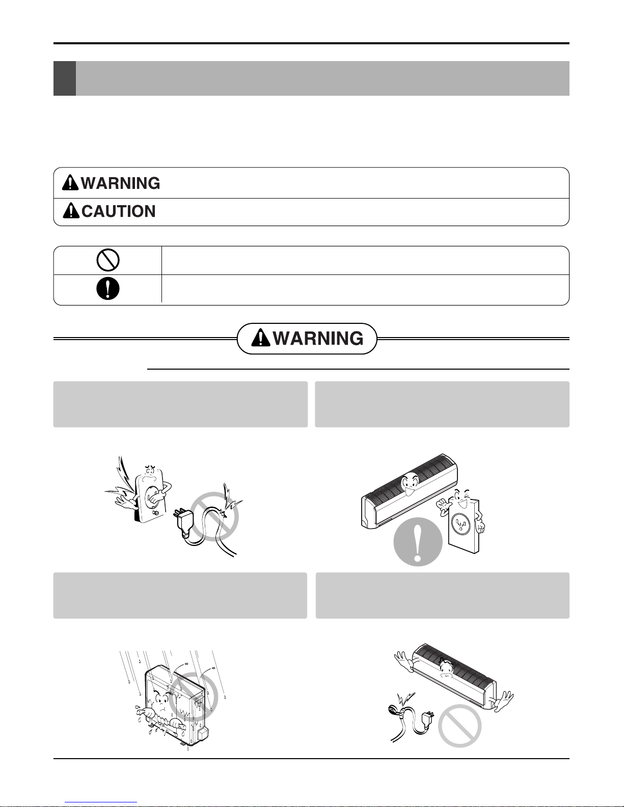
This symbol indicates the possibility of death or serious injury.
This symbol indicates the possibility of injury or damage to properties only.
Be sure not to do.
Be sure to follow the instruction.
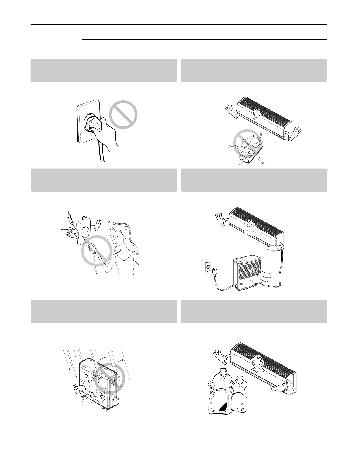
Do not use damaged power cords, plugs, or a
loose socket.
Always use the power plug and socket with the
ground terminal.
• There is risk of fire of electric shock. • There is risk of electric shock.
Install the panel and the cover of control box
securely.
.Do not modify or extend the power cord.
• There is risk of fire of electric shock. • No grounding may cause electric shock.
■ Installation
6 Room Air Conditioner
Safety Precautions
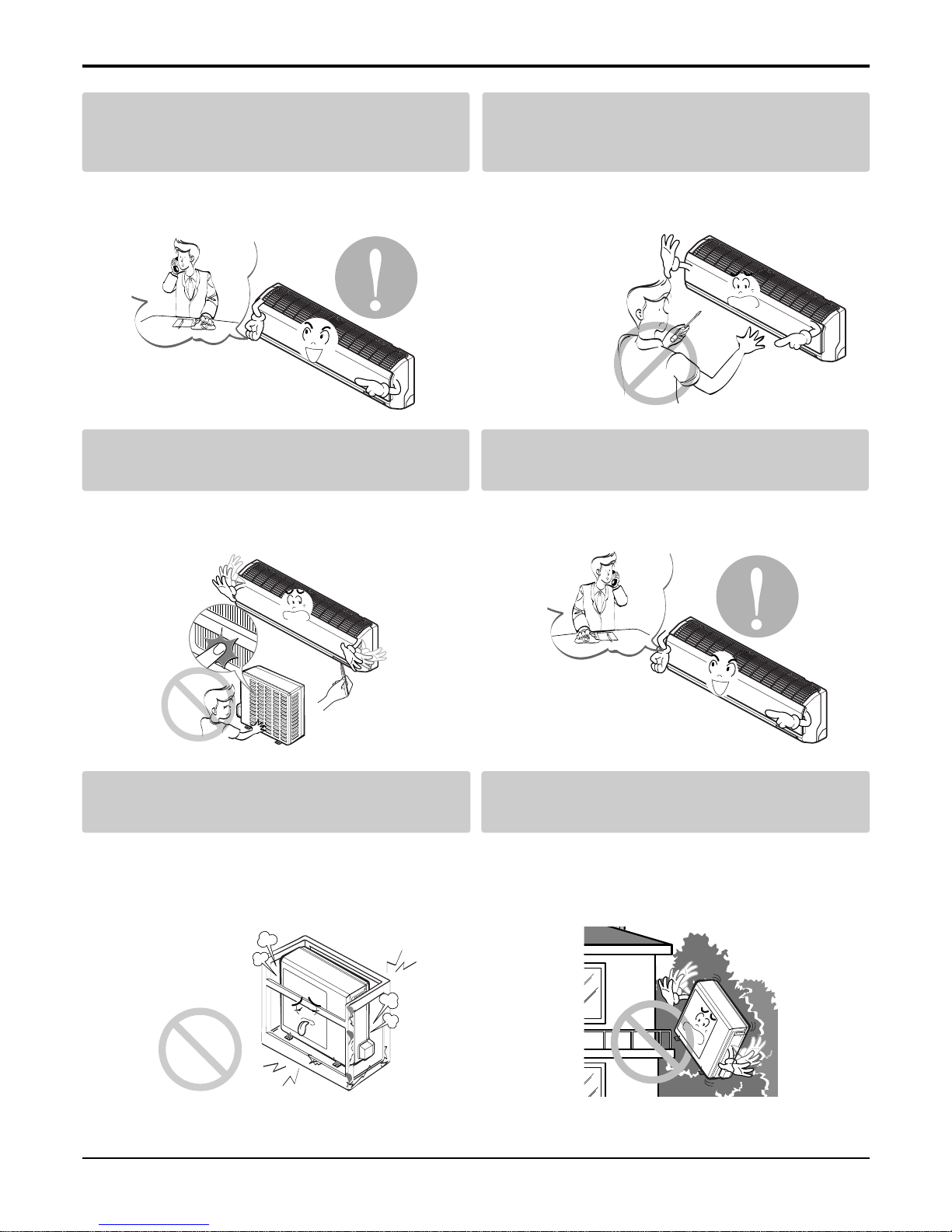
Do not install the product on a defective installation stand.
Be sure the installation area does not
deteriorate with age.
• It may cause injury, accident, or damage to the
product.
• If the base collapses, the air conditioner could fall
with it, causing property damage, product failure,
and personal injury.
• Sharp edges could cause injury. Be especially careful of the case edges and the fins on the condenser
and evaporator.
•
There is risk of fire, electric shock, explosion, or injury.
Be cautious when unpacking and installing the
product.
For installation, always contact the dealer or
an Authorized service center
For re-installation of the installed product,
always contact a dealer or an authorized service center.
Do not install, remove, or re-install the unit by
yourself.
• There is risk of fire, electric shock, explosion, or
injury.
• There is risk of fire, electric shock, explosion, or
injury.
Service Manual 7
Safety Precautions
■ Operation
Do not turn the air-conditioner ON or OFF by
plugging or unplugging the power plug.
Use a dedicated outlet for this appliance.
• There is risk of fire or electrical shock. • There is risk of fire or electrical shock.
Grasp the plug to remove the cord from the
outlet. Do not touch it with wet hands.
Do not place a heater or other appliances near
the power cable.
• There is risk of fire or electrical shock. • There is risk of fire and electric shock.
Do not allow water to run into electrical parts. Do not store or use flammable gas or com-
bustibles near the air conditioner.
• There is risk of fire, failure of the product, or electric
shock.
• There is risk of fire or failure of product.
Wax
Thinner
8 Room Air Conditioner
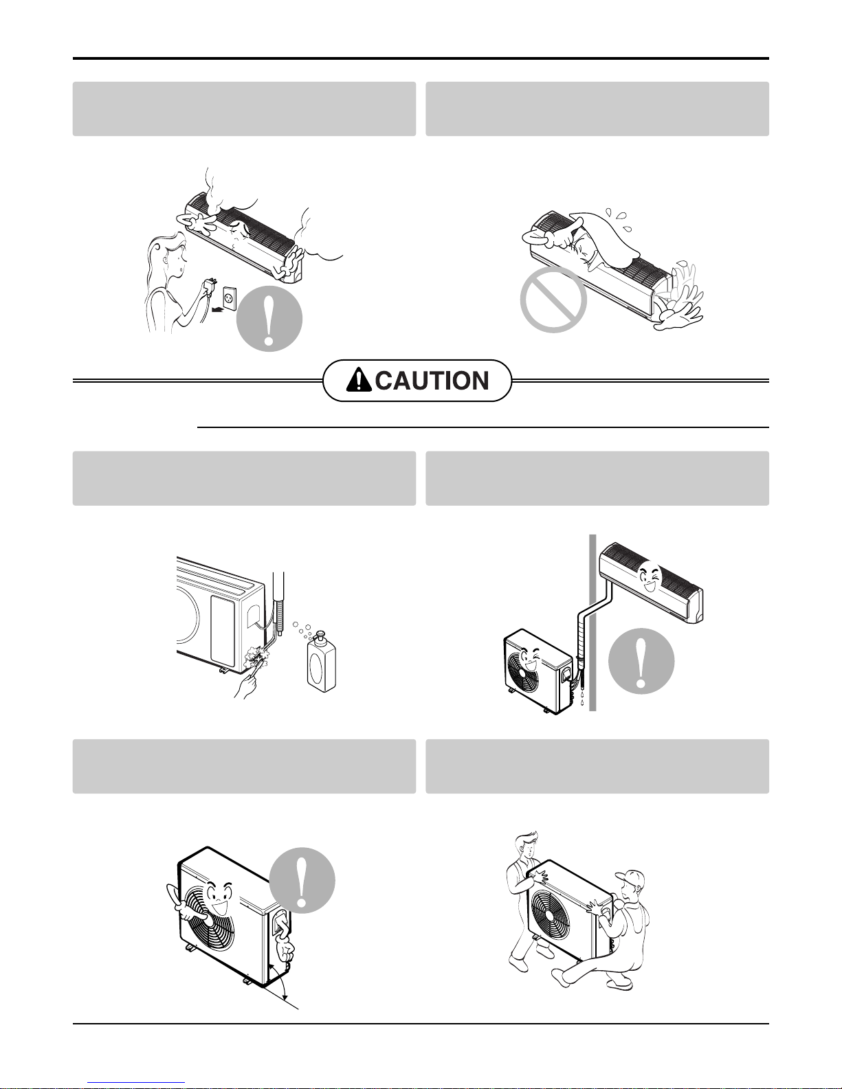
Always check for gas (refrigerant) leakage after
installation or repair of product.
Install the drain hose to ensure that water is
drained away properly.
• Low refrigerant levels may cause failure of product. • A bad connection may cause water leakage.
Keep level even when installing the product. Use two or more people to lift and transport
the air conditioner.
• To avoid vibration or water leakage. • Avoid personal injury.
■ Installation
90˚
Unplug the unit if strange sounds, odors, or
smoke comes from it.
Be cautious that water could not enter the
product.
• There is risk of electric shock or fire. • There is risk of fire, electric shock, or product damage.
Safety Precautions
Service Manual 9
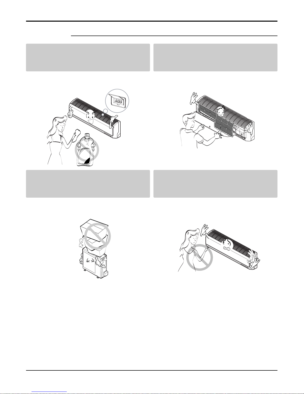
Use a soft cloth to clean. Do not use harsh
detergents, solvents, etc.
Do not touch the metal parts of the product
when removing the air filter. They are very
sharp!
• There is risk of fire, electric shock, or damage to the
plastic parts of the product.
• There is risk of personal injury.
Do not step on or put anyting on the product.
(outdoor units)
Do not insert hands or other objects through
the air inlet or outlet while the air conditioner
is plugged in.
• There is risk of personal injury and failure of product. • There are sharp and moving parts that could cause
personal injury.
■ Operation
Wax
Safety Precautions
10 Room Air Conditioner
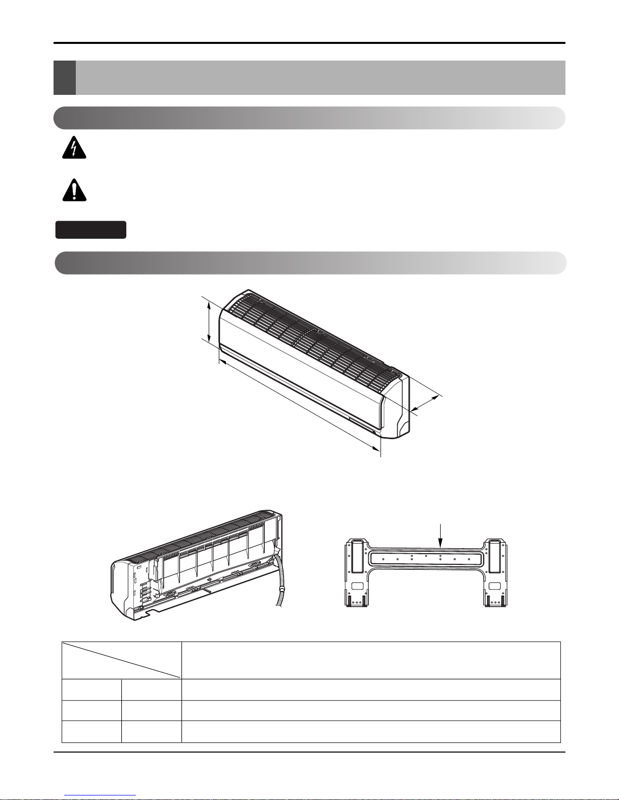
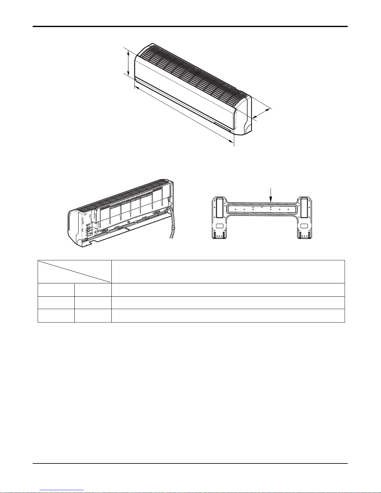
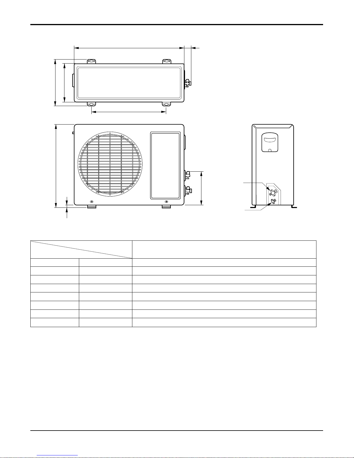
Dimensions
Dimensions
Installation plate
D
H
W
W mm 840
H mm 270
D mm 153
Model
Dimension
7k, 9k, 12k Btu Series
Indoor Unit
This symbol alerts you to the risk of electric shock.
This symbol alerts you to hazards that could cause harm to the
air conditioner.
This symbol indicates special notes.
NOTICE
Symbols Used in this Manual
Service Manual 11
Dimensions
Installation plate
D
H
W
W mm 1090
H mm 300
D mm 178
Model
Dimension
18k, 24 Btu Series
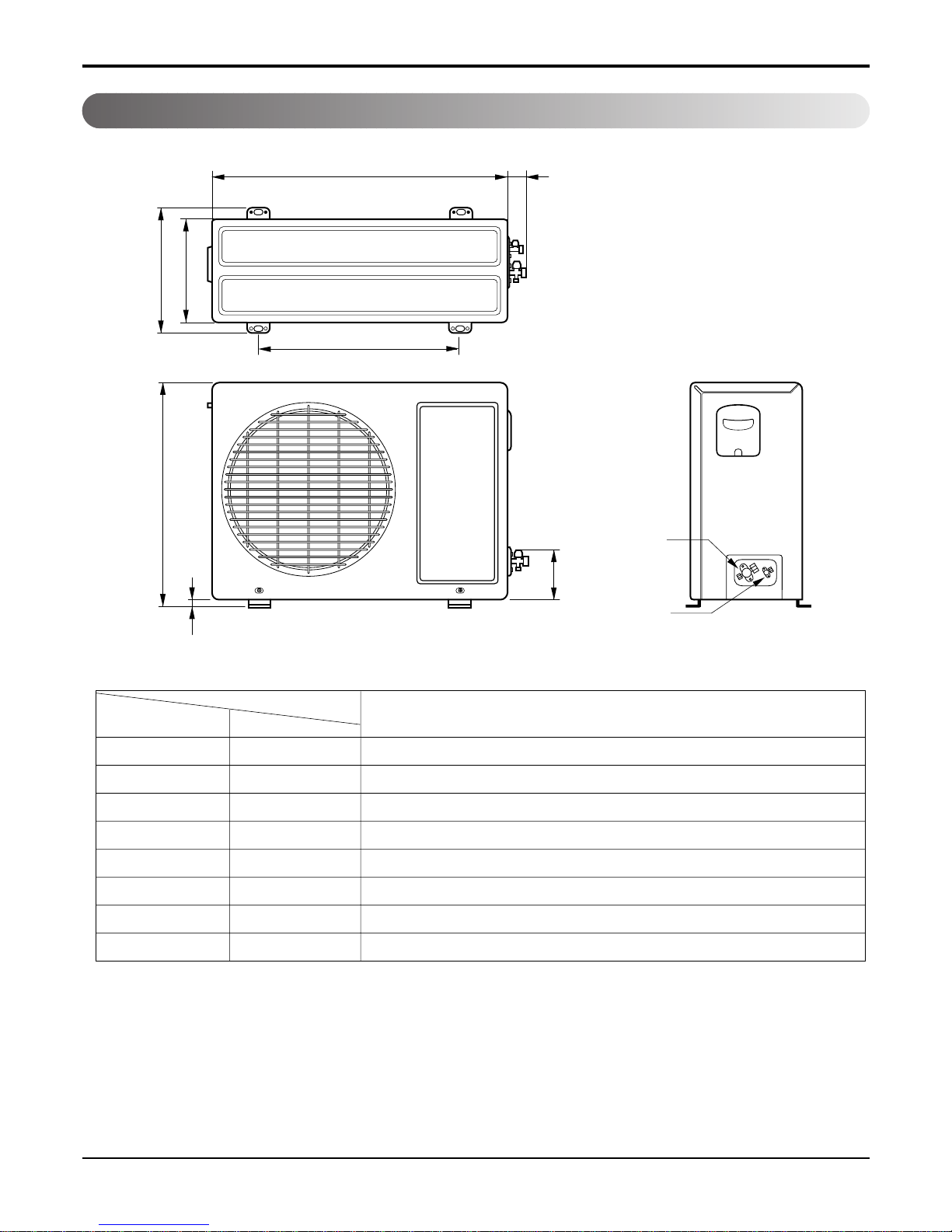
12 Room Air Conditioner
W
L2
L3
L1
D
H
L4
L5
Gas side
(3-way valve)
Liquid side
(2-way valve)
MODEL
DIM unit
W mm 717
H mm 498
D mm 229
L1 mm 270
L2 mm 56
L3 mm 464
L4 mm 17
L5 mm 130
Dimensions
Outdoor Unit
7k, 9k, 12k Series
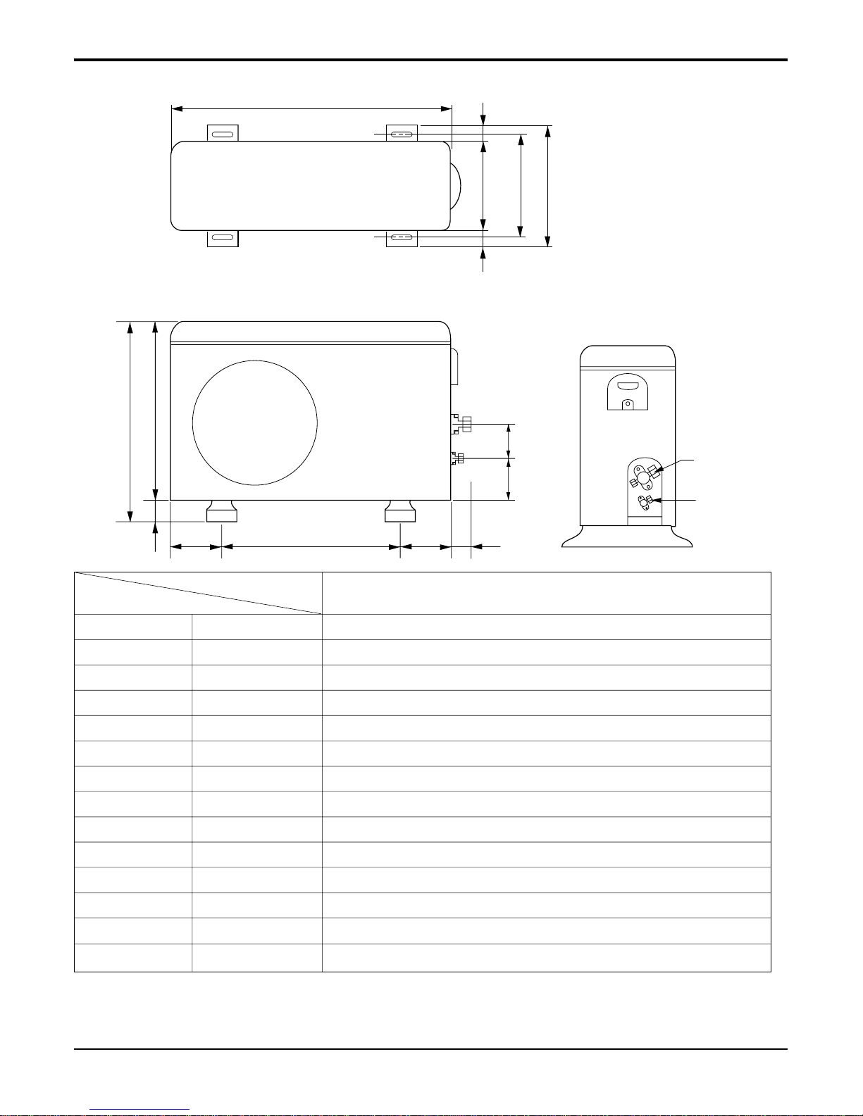
Dimensions
Service Manual 13
W
L7 L6 L8 L9
D
L1
L2
L3
L10L11
L4L5
H
Gas side
Liquid side
MODEL
DIM
W mm 870
H mm 655
D mm 320
L1 mm 370
L2 mm 340
L3 mm 25
L4 mm 630
L5 mm 25
L6 mm 546
L7 mm 162
L8 mm 162
L9 mm 54
L10 mm 74.5
L11 mm 79
AS-H2465DM0
14 Room Air Conditioner
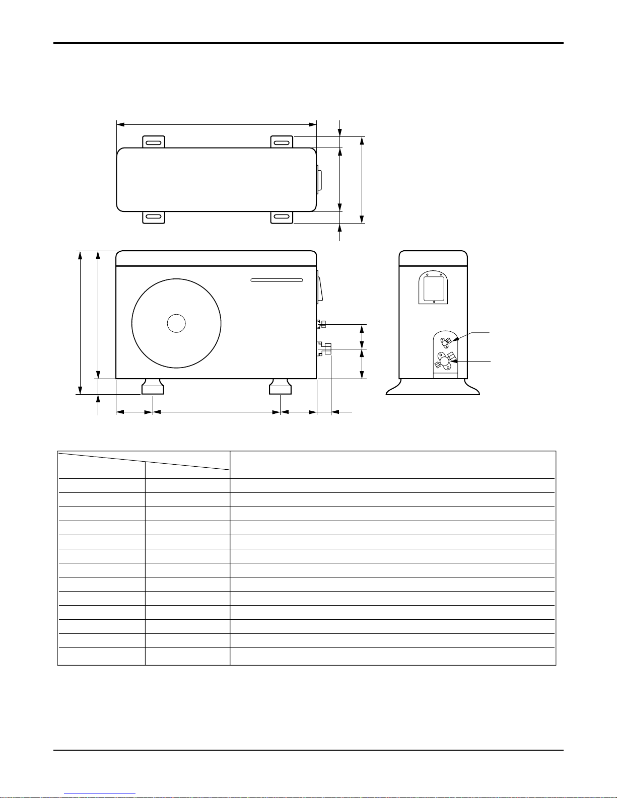
Dimensions
W
D
L1
L2
H
L3
L4
L5L6 L7 L8
L9
L10
Liquid side
2-way valve
Gas side
3-way valve
MODEL
LS-C1865DM0
DIM unit
W mm 801
H mm 555
D mm 262
L1 mm 339
L2 mm 37
L3 mm 543.6
L4 mm 11.4
L5 mm 591
L6 mm 105
L7 mm 105
L8 mm 72.5
L9 mm 86.4
L10 mm 77
Service Manual 15
Dimensions
MODEL
DIM
W
L2
L3
L1
D
H
L4
L5
Gas side
(3-way valve)
Liquid side
(2-way valve)
W mm 840
H mm 577
D mm 276
L1 mm 337
L2 mm 64
L3 mm 611
L4 mm 16
L5 mm 156
AS-C1865DM0, LS-C2465DM0, AS-C2465DM0
AS-H1865DM0, LS-H1865DM0, LS-H2465DM0
16 Room Air Conditioner
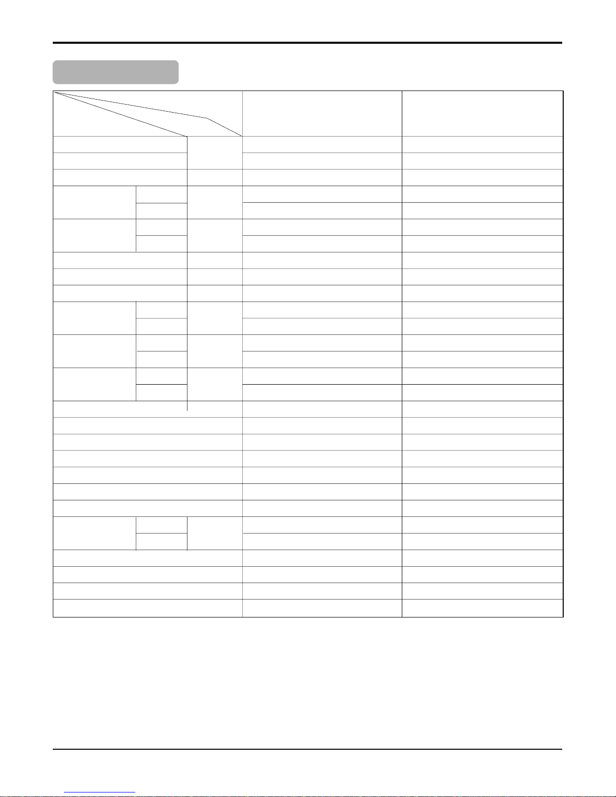
Product Specifications
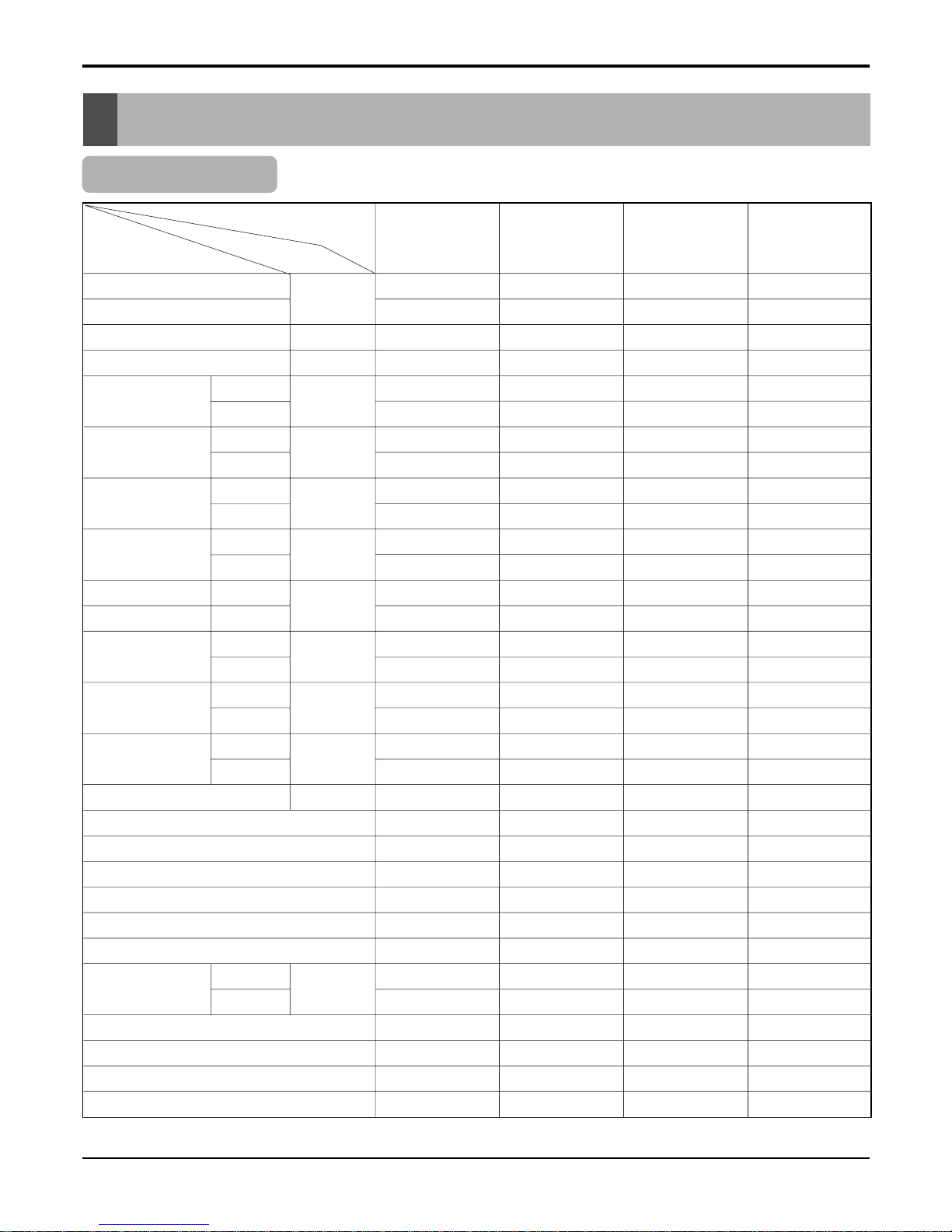
Product Specifications
Table-1
Model Name
Item Unit
Cooling Capacity
Btu/h
Heating Capacity
Moisture Removal l/h
Power Source Ø, V, Hz
Air Circulation
Indoor
m3/min
Outdoor
Noise Level
Indoor
dB (A)±3
Outdoor
Input
Cooling
W
Heating
Running
Cooling
A
Current
Heating
E.E.R. Cooling
Btu/hW
C.O.P Heating
Motor Output
Indoor
W
Outdoor
Dimensions
Indoor
mm
(W x H x D)
Outdoor
Net. Weight
Indoor
kg
Outdoor
Refrigerant g
Airflow Direction Control (Up & Down)
Airflow Direction Control (Left & Right)
Chaos Wind
Timer
Self Diagnosis
Remocon Type
Service Valve
Liquid
inch(mm)
Gas
Sleeping Operation
Drain Hose
Connecting Cable
Power Cord
7,800 9,500 12,100 12,000
8,050 10,350 13,200 13,200
1 1.2 1.2 1.2
1Ø,220-240V,50Hz 1Ø,220-240V,50Hz 1Ø,220-240V,50Hz 1Ø,220-240V,50Hz
5.0/5.7 5.8/6.6 8.8/9.5 8.8/9.5
20 20 22 22
32 33 41 41
47 47 49 49
710 860 1100 1300
690 880 1130 1250
3.1 4.1 5.3 6
3 4.2 5.1 5.8
10.98 11.0 11.0 9.2
3.42 3.42 3.42 3.1
7 7 14 14
22 22 22 22
840x270x153 840x270x153 840x270x153 840x270x153
717x481x228 717x481x228 717x481x228 717x481x228
777 7
24 24 25 27
800(R410A) 820(R410A) 850(R410A) 800(R22)
OOO O
OOO O
OOO O
24Hr ON/OFF 24Hr ON/OFF 24Hr ON/OFF 24Hr ON/OFF
OOO O
L.C.D wireless L.C.D wireless L.C.D wireless L.C.D wireless
1/4"(6.35) 1/4"(6.35) 1/4"(6.35) 1/4"(6.35)
3/8"(9.52) 3/8"(9.52) 1/2"(12.7) 1/2"(12.7)
OOO O
OOO O
1.0mm2x3, 0.75mm2x2 1.0mm2x3, 0.75mm2x2 1.0mm2x3, 0.75mm2x2 1.0mm2x3, 0.75mm2x2
1.0mm
2
1.0mm
2
1.0mm
2
1.0mm
2
AS-H0764DM0 AS-H0964DM0 AS-H1264DM0 LS-H1264DM0
Service Manual 17
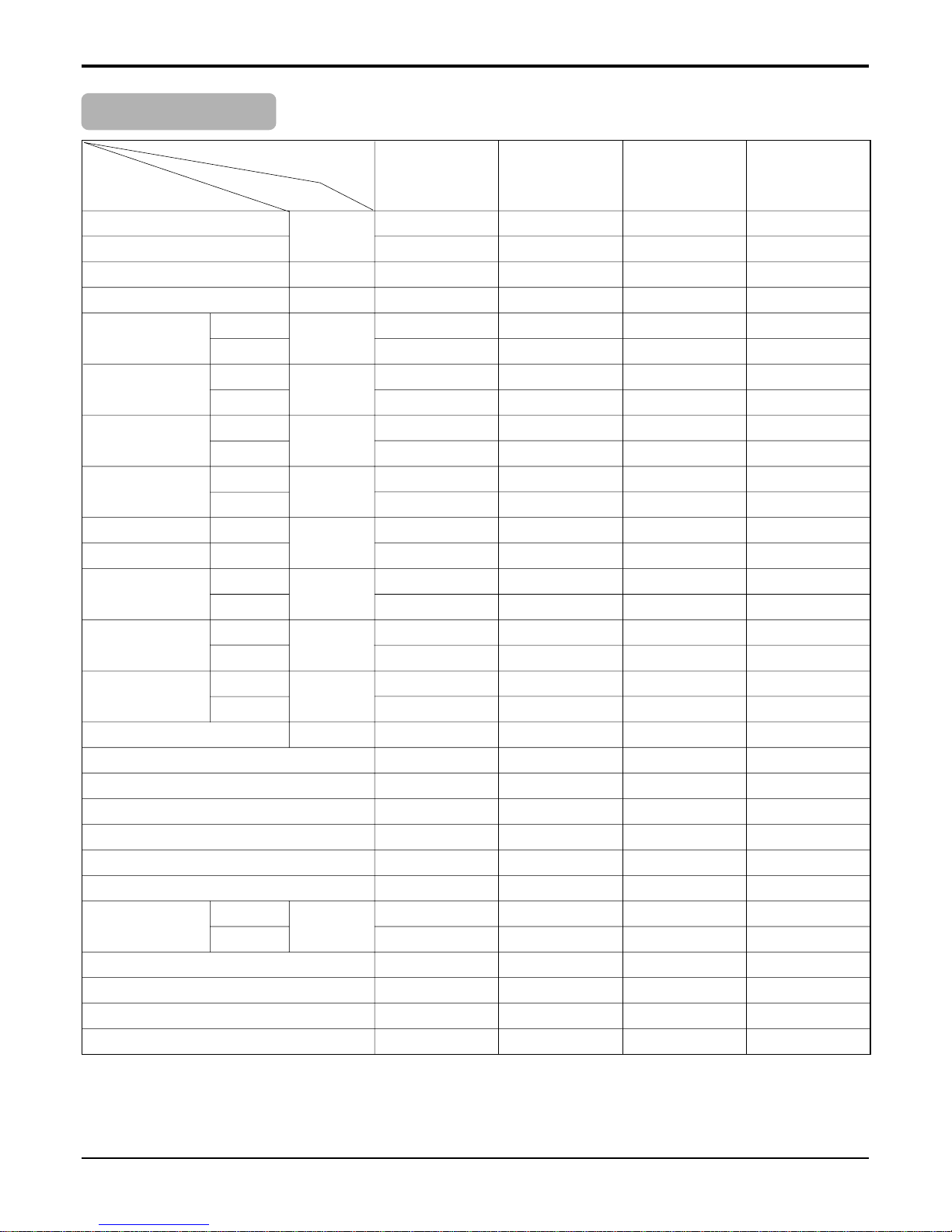
Product Specifications
Table-2
Model Name
Item Unit
Cooling Capacity
Btu/h
Heating Capacity
Moisture Removal l/h
Power Source Ø, V, Hz
Air Circulation
Indoor
m3/min
Outdoor
Noise Level
Indoor
dB (A)±3
Outdoor
Input
Cooling
W
Heating
Running
Cooling
A
Current
Heating
E.E.R. Cooling
Btu/hW
C.O.P Heating
Motor Output
Indoor
W
Outdoor
Dimensions
Indoor
mm
(W x H x D)
Outdoor
Net. Weight
Indoor
kg
Outdoor
Refrigerant g
Airflow Direction Control (Up & Down)
Airflow Direction Control (Left & Right)
Chaos Wind
Timer
Self Diagnosis
Remocon Type
Service Valve
Liquid
inch(mm)
Gas
Sleeping Operation
Drain Hose
Connecting Cable
Power Cord
9,000 7,800 9,500 12,100
9,900
1.2 1 1.2 1.2
1Ø,220-240V,50Hz 1Ø,220-240V,50Hz 1Ø,220-240V,50Hz 1Ø,220-240V,50Hz
5.8/6.6 5 5.8 8.6
20 20 20 22
33 32 33 41
47 47 47 49
950 710 860 1100
900
4.2 3.1 4.1 5.3
4
9.47 10.98 11 11
3.22
77 714
22 22 22 22
840x270x153 840x270x153 840x270x153 840x270x153
717x481x228 717x481x228 717x481x228 717x481x228
77 77
24 24 24 25
720(r22) 750(R410A) 720(R410A) 850(R410A)
OO OO
XO OO
OO OO
24Hr ON/OFF 24Hr ON/OFF 24Hr ON/OFF 24Hr ON/OFF
OO OO
L.C.A wireless L.C.A wireless L.C.A wireless L.C.A wireless
1/4"(6.35) 1/4"(6.35) 1/4"(6.35) 1/4"(6.35)
3/8"(9.52) 3/8"(9.52) 3/8"(9.52) 1/2"(12.7)
OO OO
OO OO
1.0mm2x3, 0.75mm2x2 1.0mm2x3, 0.75mm2x2 1.0mm2x3, 0.75mm2x2 1.0mm2x3, 0.75mm2x2
1.0mm
2
1.0mm
2
1.0mm
2
1.0mm
2
LS-H0964DL0 AS-C0764DM0 AS-C0964DM0 AS-C1264DM0
18 Room Air Conditioner
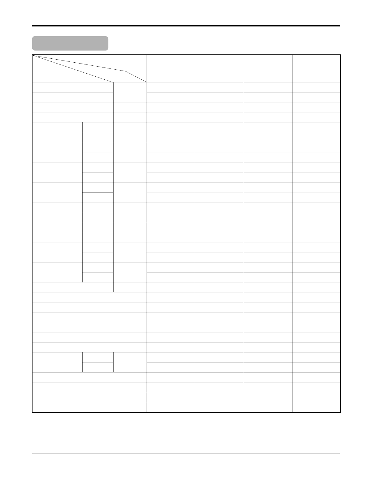
Product Specifications
Model Name
Item Unit
Cooling Capacity
Btu/h
Heating Capacity
Moisture Removal l/h
Power Source Ø, V, Hz
Air Circulation
Indoor
m3/min
Outdoor
Noise Level
Indoor
dB (A)±3
Outdoor
Input
Cooling
W
Heating
Running
Cooling
A
Current
Heating
E.E.R. Cooling Btu/hW
C.O.P Heating W/W
Motor Output
Indoor
W
Outdoor
Dimensions
Indoor
mm
(W x H x D)
Outdoor
Net. Weight
Indoor
kg
Outdoor
Refrigerant g
Airflow Direction Control (Up & Down)
Airflow Direction Control (Left & Right)
Chaos Wind
Timer
Self Diagnosis
Remocon Type
Service Valve
Liquid
inch(mm)
Gas
Sleeping Operation
Drain Hose
Connecting Cable
Power Cord
Table-3
18,500 24,000 18,500 24,000
19,800 26,400 19,800 26,400
1.8 2.9 1.8 2.9
1
Ø,220-240V,50Hz1Ø,220-240V,50Hz1Ø,220-240V,50Hz1Ø,220-240V,50Hz
13 15 13 15
42 42 42 42
40 45 40 45
56 56 56 56
1,990 2,700 1,810 2,330
1,840 2,770 1,800 2,360
9.2 12.6 8.2 10.5
8.4 12.6 8.2 10.5
9.3 8.2 10.27 10.3
3.16 2.73 3.2 3
23 25.6 23 25.6
72 82.9 72 82.9
1090 x 300 x 178 1090 x 300 x 178 1090 x 300 x 178 1090 x 300 x 178
840 x 5777 x 276 840 x 5777 x 276 840 x 5777 x 276 870 x 655 x 320
13 13 13 13
54 60 54 60
1200(R22) 1450(R22) 1250(R410A) 1450(R410A)
OO OO
OO OO
OO OO
24Hr ON/OFF 24Hr ON/OFF 24Hr ON/OFF 24Hr ON/OFF
OO OO
L.C.D wireless L.C.D wireless L.C.D wireless L.C.D wireless
1/4"(6.35) 1/4"(6.35) 3/8"(9.52) 3/8"(9.52)
1/2"(12.7) 1/2"(12.7) 5/8"(15.88) 5/8"(15.88)
OO OO
OO OO
1.5mm2x0.75mm21.5mm2x0.75mm21.5mm2x0.75mm21.5mm2x0.75mm
2
1.5mm
2
1.5mm
2
2.5mm
2
2.5mm
2
LS-H1865DM0 LS-H2665DM0 AS-H1865DM0 AS-H2465DM0
Service Manual 19
Model Name
Item Unit
Cooling Capacity Btu/h
Moisture Removal l/h
Power Source Ø, V, Hz
Air Circulation
Indoor
m3/min
Outdoor
Noise Level
Indoor
dB (A)±3
Outdoor
Input W
Running A
E.E.R. Btu/hW
Motor Output
Indoor
W
Outdoor
Dimensions
Indoor
mm
(W x H x D)
Outdoor
Net. Weight
Indoor
kg
Outdoor
Refrigerant g
Airflow Direction Control (Up & Down)
Airflow Direction Control (Left & Right)
Chaos Wind
Timer
Self Diagnosis
Remocon Type
Service Valve
Liquid
inch(mm)
Gas
Sleeping Operation
Drain Hose
Connecting Cable
Power Cord
Table-4
18,500 24,000
1.8 2.9
1
Ø,220-240V,50Hz
1
Ø,220-240V,50Hz
13 15
42 42
40 45
56 56
1,950 2,700
8.5 12.6
9.5 8.89
22 25.6
61 82.9
1090 x 300 x 178 1090 x 300 x 178
801 x 555 x 262 540 x 577 x 276
13.5 13.5
60 60
1050(R22) 1300(R22)
OO
OO
OO
24Hr ON/OFF 24Hr ON/OFF
OO
L.C.D wireless L.C.D wireless
1/4"(6.35) 3/8"(9.52)
1/2"(12.7) 5/8"(15.88)
OO
OO
1.5
mm
2
2.5
mm
2
1.5mm
2
2.5mm
2
LS-C1865DM0 LS-C2465DM0
Product Specifications
20 Room Air Conditioner
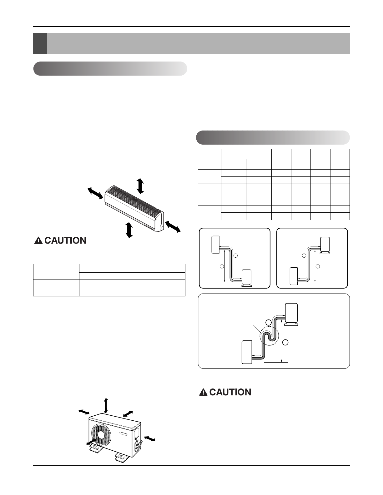
Installation
Installation
Indoor unit
• Do not have any heat or steam near the unit.
• Select a place where there are no obstacles in front of the
unit.
• Make sure that condensation drainage can be conveniently
routed away.
Do not install near a doorway.
• Ensure that the space around the left and right of the unit is
more than "A". The unit should be installed as high on the
wall as possible, allowing a minimum of "B" from ceiling.
• Use a stud finder to locate studs to prevent unnecessary
damage to the wall.
Outdoor unit
• If an awning is built over the unit to prevent direct sunlight
or rain exposure, make sure that heat radiation from the
condenser is not restricted.
• Ensure that the space around the back and sides is more
than 10cm. The front of the unit should have more than
70cm of space.
• Do not place animals and plants in the path of the warm air.
• Take the air conditioner weight into account and select a
place where noise and vibration are minimum.
• Select a place so that the warm air and noise from the air
conditioner do not disturb neighbors.
Rooftop Installations:
• If the outdoor unit is installed on a roof structure, be
sure to level the unit. Ensure the roof structure and
anchoring method are adequate for the unit location.
• Consult local codes regarding rooftop mounting.
More than 10cm
More than
5cm
More than 2.3m
More than
5cm
• Capacity is based on standard length and maximum allowance length is on the basis of reliability.
• Oil trap should be installed every 5~7 meters.
Grade
Clearance(cm)
AB
5K~28K 10 5
30K~38K 30 12
Pipe Size
Capacity
(Btu/h)
GAS LIQUID
Max.
Length
A (m)
Additional
Refrigerant
(g/m)
Max.
Elevation
B (m)
Standard
Length
(m)
5k~14k
3/8"(Ø9.52) 1/4"(Ø6.35) 4 or 7.5 7 15 20
1/2"(Ø12.7) 1/4"(Ø6.35) 4 or 7.5 7 15 20
1/2"(Ø12.7) 1/4"(Ø6.35) 4 or 7.5 15 30 20
18k~28k 5/8"(Ø15.88) 1/4"(Ø6.35) 4 or 7.5 15 30 20
5/8"(Ø15.88) 3/8"(Ø9.52) 4 or 7.5 15 30 30
30k~38k
5/8"(Ø15.88) 3/8"(Ø9.52) 7.5 15 30 30
3/4"(Ø19.05) 3/8"(Ø9.52) 7.5 15 30 50
If case more than 5m
Outdoor unit
Indoor unit
A
B
Outdoor unit
Indoor unit
A
B
A
Oil trap
Outdoor unit
Indoor unit
B
I
Selection of the Best Location
Piping Length and Elevation
Install the indoor unit on the wall where the height
from the floors more than 2.3 meters.
More than 10cm More than 10cm
More
than 60cm
More than 60cm
More than 70cm
Service Manual 21
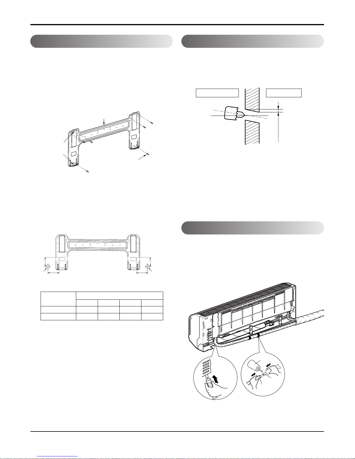
Installation
The wall you select should be strong and solid
enough to prevent vibration
1. Mount the installation plate on the wall with four
type A screws. If mounting the unit on a concrete
wall, use anchor bolts.
• Mount the installation plate horizontally by aligning
the centerline using a level.
2. Measure the wall and mark the centerline. It is
also important to use caution concerning the
location of the installation plate-routing of the
wiring to power outlets is through the walls typically. Drilling the hole through the wall for piping connections must be done safely.
• Drill the piping hole with a ø70mm hole core drill.
Drill the piping hole at either the right or the left
with the hole slightly slanted to the outdoor side.
• Open the Front Grille.
• Pass Telephone Control Cord Wire through the hole
which the power cord goes through.
• Connect Telephone Control Cord Wire to the phone jack
of telephone PCB of Control Box.
• Fix Telephone Control Cord Wire inside Control box so
as not to disconnect.
• Close the Front Grille.
How to Fix Installation Plate Drill a Hole in the Wall
Drain hose junction
• Remove the rubber stopple in the desired drain direction.
• Insert drain hose into the handle of drain pan, and join
drain hose and connecting hose according to the figure
by.
Installation Plate
Type "A" screw
Chassis
Hook
5-7mm
(3/16"~5/16")
Indoor
WALL
Outdoor
Installation plate
Left rear piping Right rear piping
Ø70mm
Ø70mm
DB
A
C
Connecting
part
Adhesive
Drain
hose
Only the
desired direction
ABCD
7k, 9k, 12k 75 65 105 65
18k, 24k 105 65 260 65
CHASSIS
(Grade)
Distance (mm)
22 Room Air Conditioner
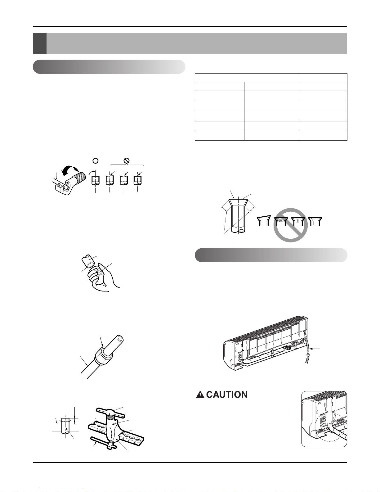
Flaring work and connection of piping
Flaring work and connection of piping
Flaring work
Flaring work
Main cause for refrigerant leakage is due to defect in the
flaring work. Carry out correct flaring work using the following procedure.
Cut the pipes and the cable.
• Use the piping kit accessory or pipes purchased locally.
• Measure the distance between the indoor and the outdoor unit.
• Cut the pipes a little longer than the measured distance.
• Cut the cable 1.5m longer than the pipe length.
Check
• Compare the flared work with figure below.
• If flare is noted to be defective, cut off the flared sec-
tion and re-flare it.
• Preparing the indoor unit's piping and drain hose for installation through the wall.
• Remove the plastic tubing retainer(see illustration below)
and pull the tubing and drain hose away from chassis.
• Replace the plastic tubing holder in the original
position.(Optional)
• Carry out flaring work using flaring tool as shown below.
Burr removal
• Completely remove all burrs from the cut cross section of
pipe/tube.
• Put the end of the copper tube/pipe in a downward direction as you remove burrs in order to avoid dropping burrs
into the tubing.
Putting nut on
• Remove flare nuts attached to indoor and outdoor unit,
then put them on pipe/tube having completed burr removal.
(not possible to put them on after flaring work)
Flaring work
• Firmly hold copper pipe in a die in the dimension shown in
the table above.
Copper
pipe
90°
Slanted Uneven Rough
Bar
Copper pipe
Clamp handle
Red arrow mark
Cone
Yoke
Handle
Bar
"A"
Inclined
Inside is shiny without scratches
Smooth all round
Even length
all round
Surface
damaged
Cracked Uneven
thickness
= Improper flaring =
Drain hose
Pipe
Reamer
Point down
Flare nut
Copper tube
mm inch mm
Ø6.35 1/4 0~0.5
Ø9.52 3/8 0~0.5
Ø12.7 1/2 0~0.5
Ø15.88 5/8 0~1.0
Ø19.05 3/4 1.0~1.3
Outside diameter A
Connection of piping -- Indoor
When install, make sure that the
remaining parts must be removed
clearly so as not to damage the piping and drain hose, especially power
cord and connecting cable.
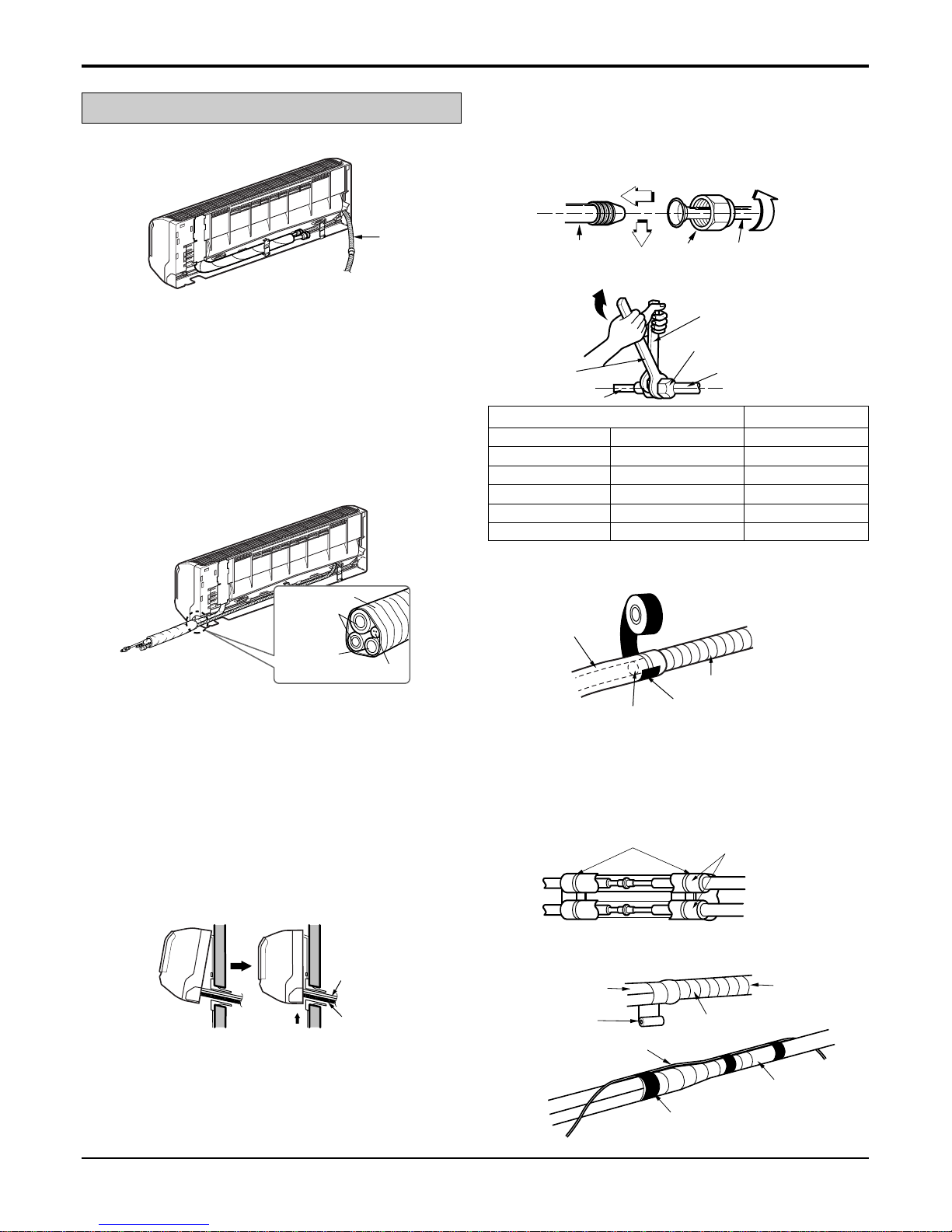
Service Manual 23
Flaring work and connection of piping
Route the indoor tubing and the drain hose in the direction of
rear right.
Drain hose
Connecting
cable
Vinyl tape(narrow)
Connection
pipe
Connecting cable
Vinyl tape
(wide)
Wrap with vinyl tape
Indoor
unit pipe
Pipe
Plastic bands
Insulation material
Vinyl tape(narrow)
Adhesive
Drain pipe
Indoor unit drain hose
Wrench
Indoor unit tubing
Open-end wrench (fixed)
Connection pipe
Flare nut
Indoor unit tubing Flare nut Pipes
Drain hose
Connecting
pipe
Connecting cable
Tape
Drain hose
Insert the connecting cable into the indoor unit from the outdoor unit through the piping hole.
• Do not connect the cable to the indoor unit.
• Make a small loop with the cable for easy connection later.
Tape the tubing, drain hose, and the connecting cable. Be
sure that the drain hose is located at the lowest side of the
bundle. Locating at the upper side can cause drain pan to
overflow inside the unit.
NOTE: If the drain hose is routed inside the room, insulate
the hose with an insulation material* so that dripping from
"sweating"(condensation) will not damage furniture or floors.
*Foamed polyethylene or equivalent is recommended.
Indoor unit installation
• Hook the indoor unit onto the upper portion of the installation plate.(Engage the two hooks of the rear top of the
indoor unit with the upper edge of the installation plate.)
Ensure that the hooks are properly seated on the installation plate by moving it left and right.
Press the lower left and right sides of the unit against the
installation plate until the hooks engage into their slots(clicking sound).
Connecting the pipings to the indoor unit and
drain hose to drain pipe.
• Align the center of the pipes and sufficiently tighten
the flare nut by hand.
• Tighten the flare nut with a wrench.
• When extending the drain hose at the indoor unit, install the
drain pipe.
Wrap the insulation material around the connecting portion.
•Overlap the connection pipe insulation material and the
indoor unit pipe insulation material. Bind them together with
vinyl tape so that there is no gap.
• Wrap the area which accommodates the rear piping housing section with vinyl tape.
mm inch kg.m
Ø6.35 1/4 1.8
Ø9.52 3/8 4.2
Ø12.7 1/2 5.5
Ø15.88 5/8 6.6
Ø19.05 3/4 6.6
Outside diameter Torque
For right rear piping
 Loading...