

LG ARX9500 Owner’s Manual

OWNER’S MANUAL
HIGH PERFORMANCE 3D
AV RECEIVER SYSTEM
Please read this manual carefully before operating
your set and retain it for future reference.
MODEL
ARX9500 (ARX9500/ARX9500W, S94P4-F/S/C/W)
NA9530P-FH.DZAFLLK_ENG_MFL67781456.indd 1NA9530P-FH.DZAFLLK_ENG_MFL67781456.indd 1 2013-02-25 3:59:462013-02-25 3:59:46
2 Safety Information
1
1
Safety Information
Safety Information
CAUTION
RISK OF ELECTRIC SHOCK
DO NOT OPEN
CAUTION: TO REDUCE THE RISK OF ELECTRIC SHOCK
DO NOT REMOVE COVER (OR BACK) NO USERSERVICEABLE PARTS INSIDE REFER SERVICING TO
QUALIFIED SERVICE PERSONNEL.
This lightning flash with arrowhead
symbol within an equilateral triangle is
intended to alert the user to the presence
of uninsulated dangerous voltage within
the product’s enclosure that may be of
sufficient magnitude to constitute a risk
of electric shock to persons.
The exclamation point within an
equilateral triangle is intended to
alert the user to the presence of
important operating and maintenance
(servicing) instructions in the literature
accompanying the product.
Cautions and Warnings
WARNING: TO PREVENT FIRE OR ELECTRIC SHOCK
HAZARD, DO NOT EXPOSE THIS PRODUCT TO RAIN
OR MOISTURE.
WARNING: Do not install this equipment in a
confined space such as a book case or similar unit.
CAUTION: The apparatus shall not be exposed to
water (dripping or splashing) and no objects filled
with liquids, such as vases, shall be placed on the
apparatus.
CAUTION: Do not block any ventilation openings.
Install in accordance with the manufacturer’s
instructions.
Slots and openings in the cabinet are provided for
ventilation and to ensure reliable operation of the
product and to protect it from over heating. The
openings shall be never be blocked by placing
the product on a bed, sofa, rug or other similar
surface. This product shall not be placed in a builtin installation such as a bookcase or rack unless
proper ventilation is provided or the manufacturer’s
instruction has been adhered to.
CAUTION concerning the Power Cord
Most appliances recommend they be placed upon a
dedicated circuit;
That is, a single outlet circuit which powers only
that appliance and has no additional outlets or
branch circuits. Check the specification page of this
owner’s manual to be certain. Do not overload wall
outlets. Overloaded wall outlets, loose or damaged
wall outlets, extension cords, frayed power cords, or
damaged or cracked wire insulation are dangerous.
Any of these conditions could result in electric
shock or fire. Periodically examine the cord of your
appliance, and if its appearance indicates damage
or deterioration, unplug it, discontinue use of the
appliance, and have the cord replaced with an exact
replacement part by an authorized service center.
Protect the power cord from physical or mechanical
abuse, such as being twisted, kinked, pinched, closed
in a door, or walked upon. Pay particular attention
to plugs, wall outlets, and the point where the cord
exits the appliance. To disconnect power from the
mains, pull out the mains cord plug. When installing
the product, ensure that the plug is easily accessible.
NA9530P-FH.DZAFLLK_ENG_MFL67781456.indd 2NA9530P-FH.DZAFLLK_ENG_MFL67781456.indd 2 2013-02-25 3:59:462013-02-25 3:59:46

3Safety Information
This device is equipped with a portable battery or
accumulator.
Safety way to remove the battery or the battery
from the equipment:
Remove the old battery or battery pack, follow the
steps in reverse order than the assembly. To prevent
contamination of the environment and bring on
possible threat to human and animal health, the
old battery or the battery put it in the appropriate
container at designated collection points. Do not
dispose of batteries or battery together with other
waste. It is recommended that you use local, free
reimbursement systems batteries and accumulators.
The battery shall not be exposed to excessive heat
such as sunshine, fire or the like.
Copyrights
It is forbidden by law to copy, broadcast, show,
broadcast via cable, play in public, or rent
copyrighted material without permission. This
product features the copy protection function
developed by Macrovision. Copy protection signals
are recorded on some discs. When recording and
playing the pictures of these discs picture noise
will appear. This product incorporates copyright
protection technology that is protected by U.S.
patents and other intellectual property rights. Use
of this copyright protection technology must be
authorized by Macrovision, and is intended for home
and other limited viewing uses only unless otherwise
authorized by Macrovision. Reverse engineering or
disassembly is prohibited.
CONSUMERS SHOULD NOTE THAT NOT ALL HIGH
DEFINITION TELEVISION SETS ARE FULLY COMPATIBLE
WITH THIS PRODUCT AND MAY CAUSE ARTIFACTS
TO BE DISPLAYED IN THE PICTURE. IN CASE OF 525
OR 625 PROGRESSIVE SCAN PICTURE PROBLEMS,
IT IS RECOMMENDED THAT THE USER SWITCH THE
CONNECTION TO THE ‘STANDARD DEFINITION’
OUTPUT. IF THERE ARE QUESTIONS REGARDING
OUR TV SET COMPATIBILITY WITH THIS MODEL 525p
AND 625p UNIT, PLEASE CONTACT OUR CUSTOMER
SERVICE CENTER.
You have to set the disc format option to [Mastered]
in order to make the discs compatible with the LG
players when formatting rewritable discs. When
setting the option to Live File System, you cannot
use it on LG players.
(Mastered/ Live File System : Disc format system for
Windows Vista)
1
Safety Information
NA9530P-FH.DZAFLLK_ENG_MFL67781456.indd 3NA9530P-FH.DZAFLLK_ENG_MFL67781456.indd 3 2013-02-25 3:59:462013-02-25 3:59:46
4
Contents
Contents
1
Safety Information
2 Cautions and Warnings
3 Copyrights
2
Preparation
6 Introduction
6 About the “
Display
6 Symbols Used in this
Manual
6 Accessories
7 Required cables
8 Remote control
10 Front panel
11 Rear panel
” Symbol
3
Installation
12 Connecting the system cable
12 Installing speakers
13 Connecting speakers
15 Connecting
video devices
15 Using an HDMI cable
17 Using a composite video
cable
18 Connecting
audio devices
19 Connecting
other devices
20 Connecting
the antennas
20 Connecting
a portable device
21 Connecting
headphones
21 Settings
21 Adjusting the Setup
Settings
22 [Language] Menu
22 [Display] Menu
23 [Audio] Menu
24 [Others] Menu
NA9530P-FH.DZAFLLK_ENG_MFL67781456.indd 4NA9530P-FH.DZAFLLK_ENG_MFL67781456.indd 4 2013-02-25 3:59:462013-02-25 3:59:46

Contents
5
4
Operation
25 Turning On the unit
25 Selecting the input source
26 Adjusting the speaker levels
27 Enjoying various sound mode
27 Sound effect
28 Bass Blast
28 Setting the USER EQ
28 Listening to FM radio
28 Automatic tuning
28 Manual tuning
29 Presetting radio stations
29 Tuning to preset stations
29 Deleting the preset stations
29 Deleting all the preset
stations
30 Playing the USB device
30 Basic operations
32 Listening to music
33 Playing a movie fi le
35 Viewing a photo
36 Dimmer
36 Screen Saver
37 Using the Sleep Timer
5
Maintenance
38 Handling the Unit
6
Troubleshooting
39 Troubleshooting
7
Appendix
41 Trademarks and Licenses
42 Specifi cations
1
2
3
4
5
6
7
NA9530P-FH.DZAFLLK_ENG_MFL67781456.indd 5NA9530P-FH.DZAFLLK_ENG_MFL67781456.indd 5 2013-02-25 3:59:462013-02-25 3:59:46
6 Preparation
2
Preparation
Introduction
2
Preparation
About the “ ” Symbol Display
“ ” may appear on your TV display during
operation and indicates that the function
explained in this owner’s manual is not
available on that specific media.
Symbols Used in this Manual
NOTE
Indicates special notes and operating features.
CAUTION
Indicates cautions for preventing possible
damages from abuse.
A section whose title has one of the following
symbols are applicable only to the disc
represented by the symbol.
MOVIE
MUSIC
PHOTO
Movie files contained in
the USB
Music files contained in
the USB
Photo les contained in
the USB
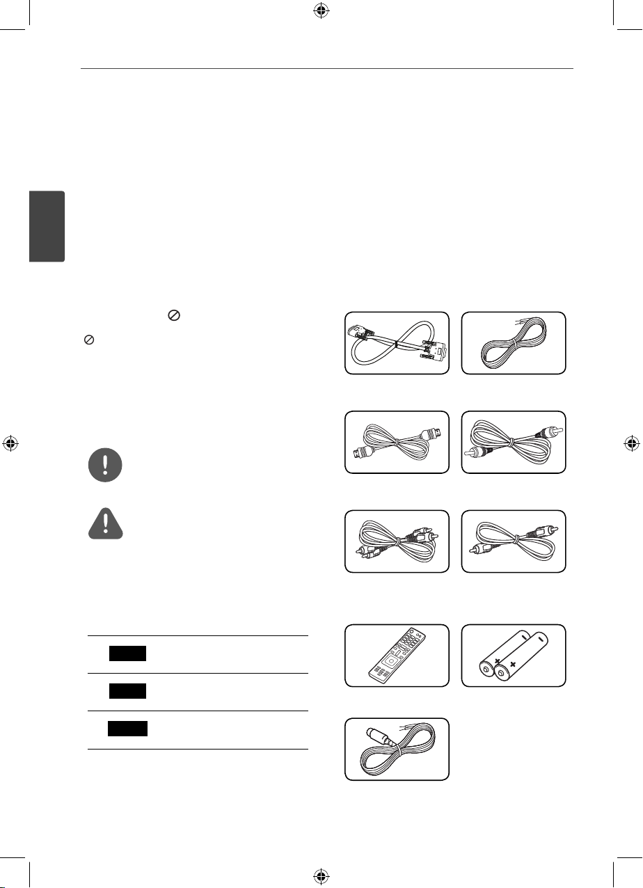
Accessories
Please check and identify the supplied
accessories.
System cable (1) Speaker cables (7)
HDMI cable (1) Coaxial cable (1)
Analog audio cable
(1)
Remote control (1) Batteries (2)
Composite video
cable (1)
FM antenna (1)
NA9530P-FH.DZAFLLK_ENG_MFL67781456.indd 6NA9530P-FH.DZAFLLK_ENG_MFL67781456.indd 6 2013-02-25 3:59:462013-02-25 3:59:46
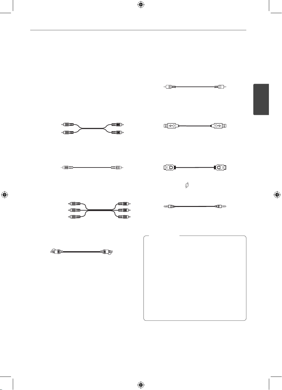
Required cables
7Preparation
The hookup diagrams on the subsequent
pages assume the use of the following
connection cables.
You must purchase the connection cables
separately if necessary.
• Analog audio cable
White (L)
Red (R)
• Composite video cable
Yellow
• Analog audio/Composite video cable
Yellow (Video)
White (L/audio)
Red (R/audio)
• Optical digital audio cable
• Coaxial digital audio cable
• USB cable
• HDMI cable
Portable cable (
•
3.5 mm Stereo plug)
Note
,
• Turn o the power to all components before
making any connections.
• When connecting an audio/video cable, be
sure to match the color-coded pins to the
appropriate jacks on the components:
yellow (video) to yellow; white (left, audio) to
white; and red (right, audio) to red.
• When connecting optical digital cables, insert
the cable plugs straight in until they click into
place.
• Do not bend or tie optical digital audio
cables.
2
Preparation
NA9530P-FH.DZAFLLK_ENG_MFL67781456.indd 7NA9530P-FH.DZAFLLK_ENG_MFL67781456.indd 7 2013-02-25 3:59:462013-02-25 3:59:46
8 Preparation
Remote control
2
Preparation
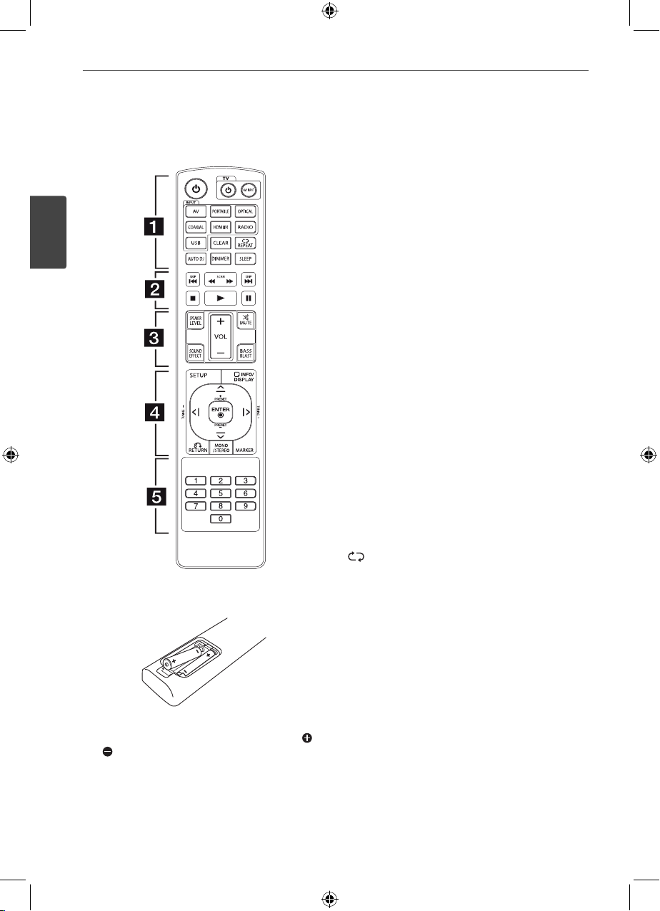
Remove the battery cover on the rear of the Remote
Control, and insert two batteries (size AAA) with
and matched correctly.
• • • • • • • • • a • • • • • • • •
POWER (1): Switches the unit ON or OFF.
TV control buttons: Controls the TV. (LG TV
only)
: Turns the TV on or off.
-1
- AV/INPUT: Switches the TV’s input source
between the TV and other input sources.
INPUT buttons: Selects the input source you
want to use. (Page 26)
- AV: Selects the input source connected to
AV IN 1/2 jack.
- PORTABLE: Selects the input source
connected to PORT. IN jack.
- OPTICAL: Selects the input source
connected to OPTICAL IN 1/2 jack.
- COAXIAL: Selects the input source
connected to COAXIAL IN 1/2 jack.
- HDMI IN: Selects the input source
connected to HDMI IN 1/2/3 jack.
- RADIO: Selects the FM.
- USB: Selects the input source connected to
USB port.
CLEAR: Deletes a preset stations. (Page 29)
REPEAT: Selects a play mode. (Repeat
playback/ Random playback) (Page 33)
AUTO DJ: Selects the AUTO DJ mode.
(Page 33)
DIMMER: The display window is darken by half
and the Backlightings will be turned off.
(Page 36)
SLEEP: Sets the system to turn off
automatically at a specified time. (Page 37)
NA9530P-FH.DZAFLLK_ENG_MFL67781456.indd 8NA9530P-FH.DZAFLLK_ENG_MFL67781456.indd 8 2013-02-25 3:59:462013-02-25 3:59:46
9Preparation
• • • • • • • • • b • • • • • • • •
C/V
(SKIP): Goes to the next or previous
chapter / track / file.
c/v
(SCAN): Searches backward or
forward.
Z
(STOP): Stops playback.
z
(PLAY): Starts playback.
M
(PAUSE): Pauses playback.
• • • • • • • • • c • • • • • • • •
SPEAKER LEVEL: Sets the sound level of
desired speaker. (page 26)
SOUND EFFECT: Selects a sound effect mode.
(Page 27)
VOL (-/+): Adjusts speaker volume.
MUTE (
): Turns off the sound temporarily.
Press the button again to restore the sound.
BASS BLAST: Selects the BASS BLAST sound
mode directly. (Page 28)
• • • • • • • • • d • • • • • • • •
SETUP: Displays or exits the [SETUP] menu.
RETURN (x): Moves backwards in the menu
or exits the setup menu.
INFO/DISPLAY (
): Displays or exits On-screen
Display. (Page 33,34,36)
ENTER (
): Acknowledges menu selection.
MARKER: Marks music files on the [MUSIC]
menu. (Page 32)
PRESET (-/+): Selects a preset stations.
TUNING (-/+): Tunes in the desired radio
station.
W/S/A/D
(up/ down/ left/ right): Selects an
option in the menu.
MONO/STEREO: Selects mono/stereo in FM
mode. (Page 28)
• • • • • • • • • e • • • • • • • •
0 to 9 numerical buttons: Selects numbered
options in a menu.
2
Preparation
NA9530P-FH.DZAFLLK_ENG_MFL67781456.indd 9NA9530P-FH.DZAFLLK_ENG_MFL67781456.indd 9 2013-02-25 3:59:472013-02-25 3:59:47
10 Preparation
Front panel
AV RECEIVER SYSTEM
a
b
cde
2
Preparation
f
eghij
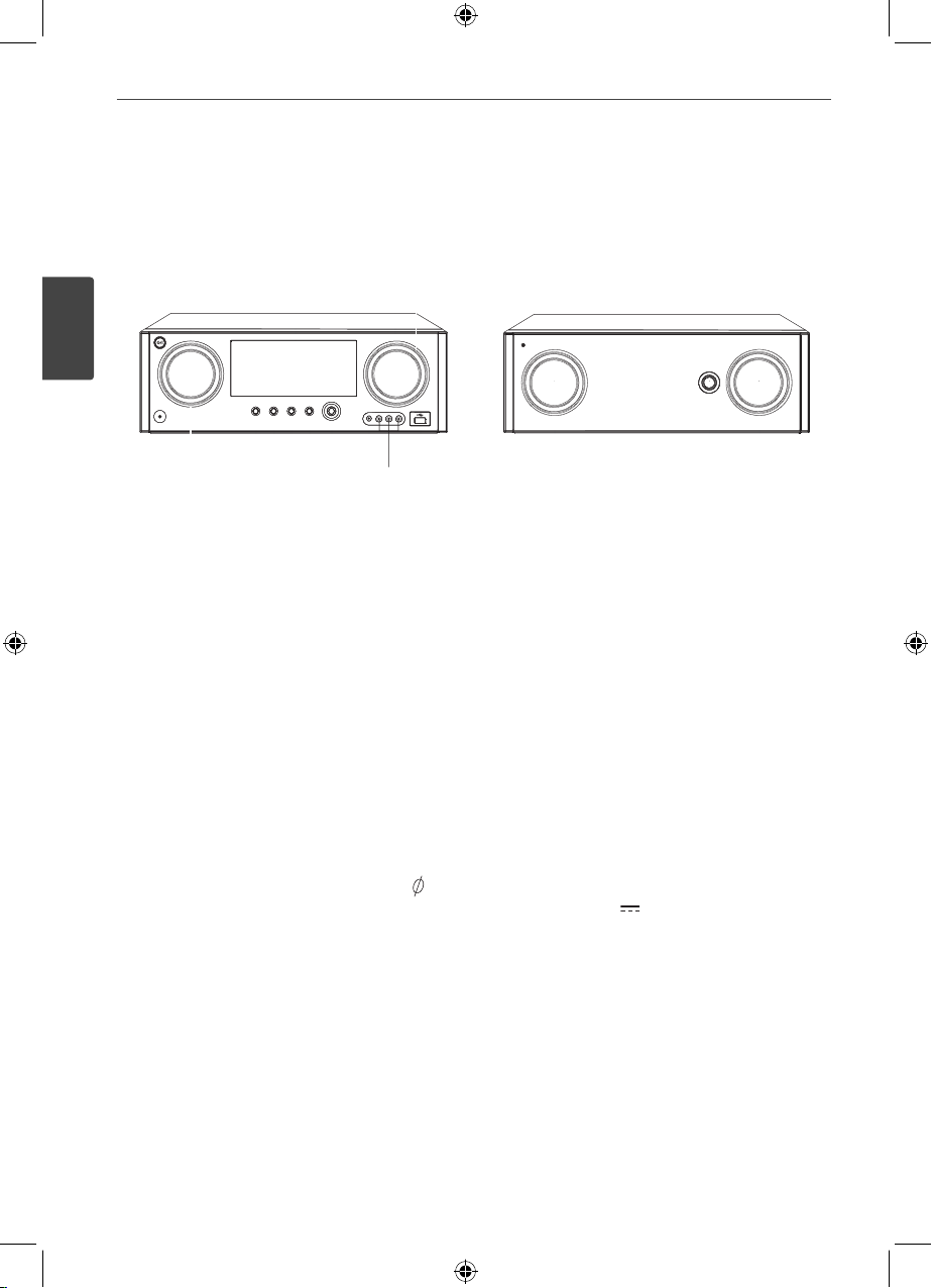
STANDBY/ON (1/!)
a
Switches the unit ON or OFF.
INPUT SELECTION
b
Selects the input source. Rotate this knob
until the input source you want appears on
the display window.
Display window
c
Shows the current status of the unit.
MASTER VOLUME
d
Adjusts the speaker volume.
Backlighting
e
Turns on the unit, the backlightings light
up.
PHONES connector
f
Connects a stereo headphone plug (
3.5 mm) to PHONES connector for private
listening. (Page 21)
USER EQ
g
Sets the USER EQ mode (BASS, MIDDLE
and TREBLE). (Page 28)
ENTER
h
Acknowledges menu selection.
PLAY / PAUSE
i
Starts playback.
Pauses playback, press it again to exit
pauses status.
k
lm n
SUBWOOFER AMPLIFIER
opq
Moves to the BASS mode if you press
PLAY/PAUSE on the front panel while
the “USER EQ” is displayed in the display
window.
STOP
j
Stops playback.
MULTI CONTROL
k
Adjusts the various options.
PORT. IN
l
Connects a portable device (MP3 player,
etc) to PORT. IN jack.
AV IN 2 (L-AUDIO-R, VIDEO)
m
Connects the components with analog
audio/video output jacks (camcorder,
video game console, etc).
USB port (5 V
n
500 mA)
Connects an USB device to USB port.
SOUND EFFECT
o
Selects a sound effect mode. (Page 27)
BASS BLAST
p
Selects the BASS BLAST sound mode
directly. (Page 28)
SUBWOOFER VOLUME
q
Adjusts the subwoofer level.
NA9530P-FH.DZAFLLK_ENG_MFL67781456.indd 10NA9530P-FH.DZAFLLK_ENG_MFL67781456.indd 10 2013-02-25 3:59:472013-02-25 3:59:47
Rear panel
a
11Preparation
AV RECEIVER SYSTEM
b
d
ce
f
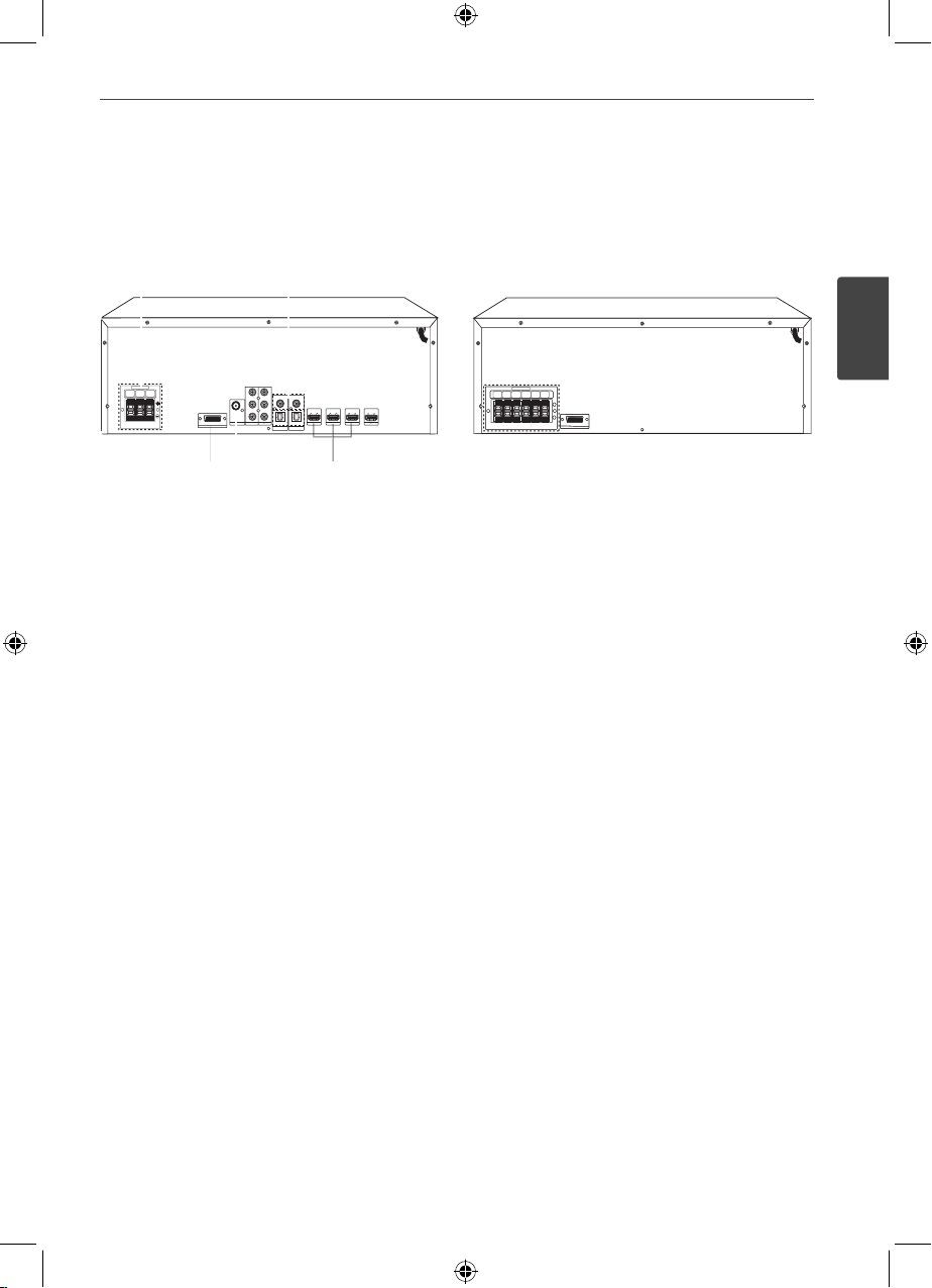
Speakers connectors
a
g
i
h
Connects the speaker cables.
COAXIAL IN 1/2
b
(DIGITAL AUDIO IN 1/2)
Connects other components with a
coaxial digital audio output.
SYSTEM Connector
c
Connects the system cable.
ANTENNA connectors
d
FM – Connects the FM wired antenna.
AV IN 1 (VIDEO IN, L-AUDIO-R)
e
Connects the components with analog
audio/video output jacks.
SUBWOOFER AMPLIFIER
ac
OUTPUT (VIDEO OUT, L-AUDIO-R)
f
Connects the components with analog
audio/video input jacks.
OPTICAL IN 1/2
g
(DIGITAL AUDIO IN 1/2)
Connects other components with an
optical digital audio output.
HDMI IN 1/2/3
h
Connects the component with HDMI
output.
HDMI OUT
i
Connects a TV or component with HDMI
input.
2
Preparation
NA9530P-FH.DZAFLLK_ENG_MFL67781456.indd 11NA9530P-FH.DZAFLLK_ENG_MFL67781456.indd 11 2013-02-25 3:59:472013-02-25 3:59:47
12 Installation
3
Installation
Connecting the
system cable
3
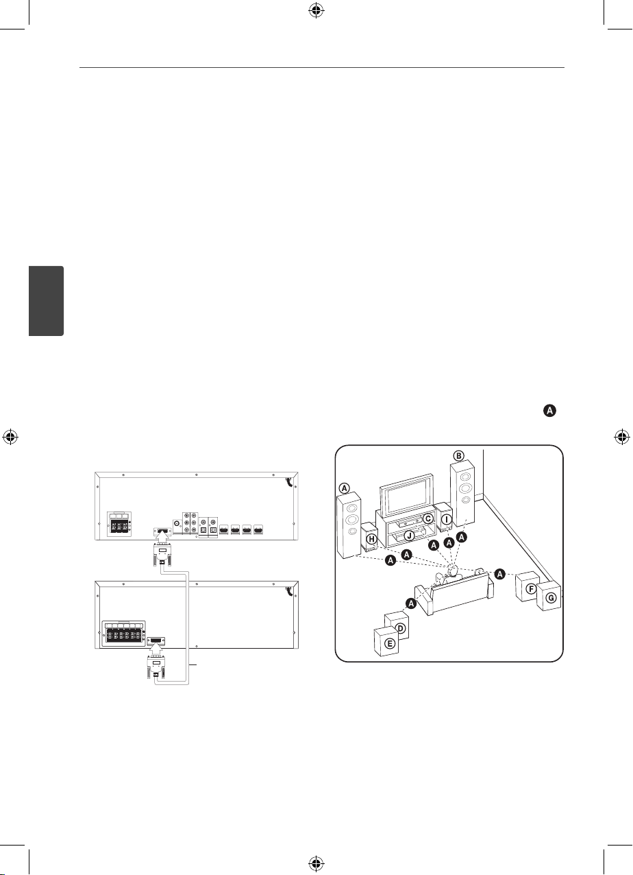
You can enjoy 7.2 channel surround sound by
Installation
using this unit.
It is necessary to connect the system cable
before using this unit. If the system cable is
not connected, ‘CHECK CABLE’ appears on the
display window every 10 seconds.
Before connecting the system cable, be sure to
disconnect the AC power cord.
AV Receiver System
Subwoofer Amplifier
Installing speakers
The unit allows you to use 7.2 channel system.
The following illustration shows an example
of positioning the system. Note that the
illustrations in these instructions di er from the
actual unit for explanation purposes. For the
best possible rear sound, all the speakers other
than the subwoofer should be placed at the
same distance from the listening position (
F
).
System cable
Connect the SYSTEM jack on the AV Receiver
System and Subwoofer Ampli er using a
system cable.
NA9530P-FH.DZAFLLK_ENG_MFL67781456.indd 12NA9530P-FH.DZAFLLK_ENG_MFL67781456.indd 12 2013-02-25 3:59:472013-02-25 3:59:47
13Installation
Front speaker (left)
Front speaker (right)
Place the front speakers to the sides of the
monitor or screen and as ush with the screen
surface as possible.
Center speaker
Place the center speaker above or below the
monitor or screen.
/ Surround speaker (left) 1, 2
/ Surround speaker (right) 1, 2
Place these speakers behind your listening
position, facing slightly inwards.
/ Subwoofer 1, 2
The position of the subwoofer is not so
critical, because low bass sounds are not
highly directional. But it is better to place
the subwoofer near the front speakers. Turn
it slightly toward the center of the room to
reduce the wall re ections.
Unit
Caution
>
• Do not stack the speakers
and be careful that the
speaker should not fall
down. Otherwise it may
result in the speaker
malfunctioning and
causing personal injury
and/or property damage.
• Make sure to install the speaker with other
people in order to prevent it from falling and
causing injuries to the installer.
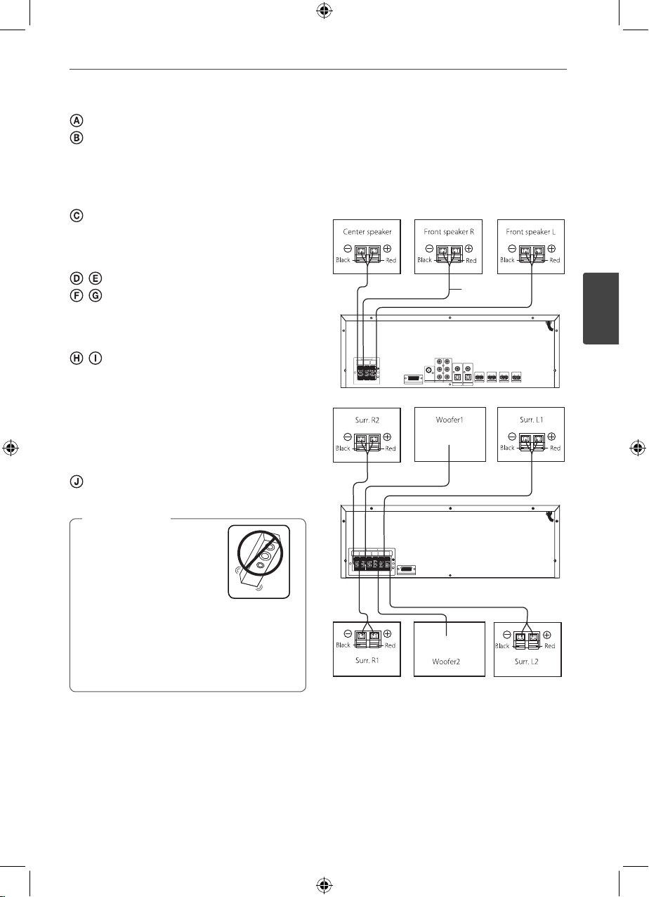
Connecting speakers
Before connecting the cables, be sure to
disconnect the AC power cord.
Speaker
Cable
3
Installation
AV Receiver System
Subwoofer Amplifier
NA9530P-FH.DZAFLLK_ENG_MFL67781456.indd 13NA9530P-FH.DZAFLLK_ENG_MFL67781456.indd 13 2013-02-25 3:59:472013-02-25 3:59:47
14 Installation
1. Connect the wires to the unit. To connect
the cable to the unit, press each plastic
nger pad to open the connection terminal.
Insert the wire and release the nger pad.
Connect the black end of each wire to the
3
Installation
terminals marked - (minus) and the other
end to the terminals marked + (plus).
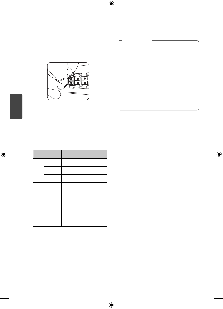
2. Connect the wires to the speakers. Connect
the other end of each wire to the correct
speaker according to the color coding:
Color Speaker Position
Green Center Center
Red Front Front right
System
AV Receiver
White Front Front left
Yellow Surr. R2 Surr. right
Grey Surr. R1 Surr. right
Orange Subwoofer
1, 2
Blue Surr. L1 Surr. left
Purple Surr. L2 Surr. left
Subwoofer Amplifier
Any front
position
Caution
>
• Be careful to make sure children not to put
their hands or any objects into the *speaker
duct.
*Speaker duct : A hall for plentiful bass sound
on speaker cabinet (enclosure).
• Place the center speaker at a safe distance
from the child’s reach. Otherwise it may result
in the speaker falling down and causing
personal injury and/or property damage.
• The speakers contain magnet parts, so color
irregularity may occur on the TV screen or PC
monitor screen. Please use the speakers far
away from either TV screen or PC monitor.
To connect the cable to the speakers,
press each plastic nger pad to open the
connection terminals on the base of each
speaker. Insert the wire and release the
nger pad.
NA9530P-FH.DZAFLLK_ENG_MFL67781456.indd 14NA9530P-FH.DZAFLLK_ENG_MFL67781456.indd 14 2013-02-25 3:59:472013-02-25 3:59:47
 Loading...