

LG ARWN072BA2, ARWN144BA2, ARWN216BA2, ARWN288BA2, ARWN360BA2 Installation Manual
...
INSTALLATION MANUAL
AIR CONDITIONER
• Please read this installation manual completely before installing the product.
• Installation work must be performed in accordance with the national
wiring standards by authorized personnel only.
• Please retain this installation manual for future reference after reading
it thoroughly.your set and retain it for future reference.
P/NO : MFL63748901
www.lge.com
MODELS: ARWN Series
ENGLISH FRANCAIS ESPAÑOL
2 Outside Unit
ARWN Series Outside unit Installation Manual
TABLE OF CONTENTS
Safety Precautions .........................................................................................................3
Installation Process .......................................................................................................7
Outside units Information..............................................................................................8
Environment-friendly Alternative Refrigerant R410A ..............................................10
Select the Best Location..............................................................................................10
Installation space .........................................................................................................11
Water control ...............................................................................................................13
Lifting method ..............................................................................................................15
Installation ....................................................................................................................16
Refrigerant piping installation ....................................................................................20
Protection device unit..................................................................................................25
Refrigerant piping system ..........................................................................................27
Y branch pipe and header branch pipe type .............................................................44
Leakage test and vacuum ...........................................................................................46
Electrical Wiring ...........................................................................................................48
Test Run ........................................................................................................................64
Cooling tower applied method ...................................................................................73
Caution For Refrigerant Leak......................................................................................74
Water Solenoid Valve Control ....................................................................................76
Installation Manual 3
ENGLISH
Safety Precautions
Safety Precautions
To prevent injury to the user or other people and property damage, the following instructions must
be followed.
n Incorrect operation due to ignoring instruction will cause harm or damage. The seriousness is
classified by the following indications.
n Meanings of symbols used in this manual are as shown below.
This symbol indicates the possibility of death or serious injury.
This symbol indicates the possibility of injury or damage to properties only.
Be sure not to do.
Be sure to follow the instruction.
n Installation
Have all electric work done by a licensed electrician
according to "Electric Facility Engineering Standard"
and "Interior Wire Regulations" and the instructions
given in this manual and always use a special circuit.
• If the power source capacity is inadequate or electric work is performed improperly, electric shock or fire may result.
Ask the dealer or an authorized technician to install
the air conditioner.
• Improper installation by the user may result in water leakage, electric
shock, or fire.
Always ground the product.
• There is risk of fire or electric shock.
Always intstall a dedicated circuit and breaker.
• Improper wiring or installation may cause fire or electric shock.
For re-installation of the installed product, always contact a dealer or an Authorized Service Center.
• There is risk of fire, electric shock, explosion, or injury.
Do not install, remove, or re-install the unit by yourself
(customer).
• There is risk of fire, electric shock, explosion, or injury.
Do not store or use flammable gas or
combustibles near the air conditioner.
• There is risk of fire or failure of product.
Use the correctly rated breaker or fuse.
• There is risk of fire or electric shock.
Do not install the unit outdoor.
• Otherwise it may cause fire, electric shock and trouble
Do not install the product on a defective installation stand.
• It may cause injury, accident, or damage to the product.
When installing and moving the air conditioner to
another site, do not charge it with a different refrigerant
from the refrigerant specified on the unit.
• If a different refrigerant or air is mixed with the original refrigerant, the
refrigerant cycle may malfunction and the unit may be damaged.
Do not reconstruct to change the settings of the protection devices.
• If the pressure switch, thermal switch, or other protection device is
shorted and operated forcibly, or parts other than those specified by
LGE are used, fire or explosion may result.
4 Outside Unit
Safety Precautions
Ventilate before operating air conditioner when gas
leaked out.
• It may cause explosion, fire, and burn.
Securely install the cover of control box and the panel.
• If the cover and panel are not installed securely, dust or water may
enter the outside unit and fire or electric shock may result.
If the air conditioner is installed in a small room, measures must be taken to prevent the
refrigerant concentration from exceeding the safety limit when the refrigerant leaks.
• Consult the dealer regarding the appropriate measures to prevent the safety limit from being exceeded. Should the refrigerant leak and cause the
safety limit to be exceeded, harzards due to lack of oxygen in the room could result.
n Operation
Do not damage or use an unspecified power cord.
• There is risk of fire, electric shock, explosion, or injury.
Use a dedicated outlet for this appliance.
• There is risk of fire or electrical shock.
Be cautious that water could not enter the product.
• There is risk of fire, electric shock, or product damage.
Do not touch the power switch with wet hands.
• There is risk of fire, electric shock, explosion, or injury.
When the product is soaked (flooded or
submerged), contact an Authorized Service Center.
• There is risk of fire or electric shock.
Be cautious not to touch the sharp edges when
installing.
• It may cause injury.
Take care to ensure that nobody could step on or fall
onto the outside unit.
• This could result in personal injury and product damage.
Do not open the inlet grille of the product during operation. (Do not touch the electrostatic filter, if the unit is
so equipped.)
• There is risk of physical injury, electric shock, or product failure.
n Installation
Always check for gas (refrigerant) leakage after installation or repair of product.
• Low refrigerant levels may cause failure of product.
Do not install the product where the noise or hot air from
the outside unit could damage the neighborhoods.
• It may cause a problem for your neighbors.
Keep level even when installing the product.
• To avoid vibration or water leakage.
Do not install the unit where combustible gas may leak.
• If the gas leaks and accumulates around the unit, an explosion may result.
Use power cables of sufficient current
carrying capacity and rating.
• Cables that are too small may leak, generate heat, and cause a fire.
Do not use the product for special purposes, such as preserving foods, works of art, etc. It is a consumer air conditioner, not a precision refrigeration system.
• There is risk of damage or loss of property.
Keep the unit away from children. The heat exchanger is
very sharp.
• It can cause the injury, such as cutting the finger. Also the damaged fin may
result in degradation of capacity.
When installting the unit in a hospital, communication station, or similar place, provide sufficient protection against
noise.
• The inverter equipment, private power generator, high-frequency medical equipment, or
radio communication equipment may cause the air conditioner to operate erroneously, or
fail to operate. On the other hand, the air conditioner may affect such equipment by creating noise that disturbs medical treatment or image broadcasting.

Installation Manual 5
ENGLISH
Safety Precautions
Do not install the product where it is exposed to sea wind (salt spray) directly.
• It may cause corrosion on the product. Corrosion, particularly on the condenser and evaporator fins, could cause product malfunction or inefficient operation.
n Operation
Do not use the air conditioner in special environments.
• Oil, steam, sulfuric smoke, etc. can significantly reduce the performance of
the air conditioner or damage its parts.
Do not block the inlet or outlet.
• It may cause failure of appliance or accident.
Make the connections securely so that the outside force of
the cable may not be applied to the terminals.
• Inadequate connection and fastening may generate heat and cause a fire.
Be sure the installation area does not deteriorate with age.
• If the base collapses, the air conditioner could fall with it, causing property
damage, product failure, or personal injury.
Safely dispose of the packing materials.
• Packing materials, such as nails and other metal or wooden parts, may
cause stabs or other injuries.
• Tear apart and throw away plastic packaging bags so that children may not
play with them. If children play with a plastic bag which was not torn apart,
they face the risk of suffocation.
Turn on the power at least 6 hours before starting operation.
• Starting operation immediately after turning on the main power switch can
result in severe
damage to internal parts. Keep the power switch turned on during the operational season.
Be very careful about product transportation.
• Only one person should not carry the product if it weighs more than 20 kg.
• Some products use PP bands for packaging. Do not use any PP bands for a means of transportation. It is dangerous.
• Do not touch the heat exchanger fins. Doing so may cut your fingers.
• When transporting the outside unit, suspending it at the specified positions on the unit base. Also support the outside unit at four points so that it cannot slip
sideways.
Do not touch any of the refrigerant piping during and after
operation.
• It can cause a burn or frostbite.
Do not operate the air conditioner with the panels or
guards removed.
• Rotating, hot, or high-voltage parts can cause injuries.
Do not directly turn off the main power switch after stopping operation.
• Wait at least 5 minutes before turning off the main power switch. Otherwise
it may result in water leakage or other problems.
Auto-addressing should be done in condition of connecting the power of all indoor and outdoour units. Autoaddressing should also be done in case of changing the
indoor unit PCB.
Use a firm stool or ladder when cleaning or maintaining
the air conditioner.
• Be careful and avoid personal injury.
6 Outside Unit
Safety Precautions
When wiring:
Electrical shock can cause severe personal injury or death. Only a qualified,
experienced electrician should attempt to wire this system.
• Do not supply power to the unit until all wiring and tubing are completed or reconnected and checked.
• Highly dangerous electrical voltages are used in this system. Carefully refer to the wiring diagram and these
instructions when wiring. Improper connections and inadequate grounding can cause accidental injury or death.
• Ground the unit following local electrical codes.
• Connect all wiring tightly. Loose wiring may cause overheating at connection points and a possible fire hazard.
When transporting:
Be careful when picking up and moving the indoor and outdoor units. Get a partner to help, and
bend your knees when lifting to reduce strain on your back. Sharp edges or thin aluminum fins on
the air conditioner can cut your finger.
When installing...
... in a wall: Make sure the wall is strong enough to hold the unit's weight.
It may be necessary to construct a strong wood or metal frame to provide added support.
... in a room: Properly insulate any tubing run inside a room to prevent "sweating" that can cause
dripping and water damage to wall and floors.
... in moist or uneven locatinons: Use a raised concrete pad or concrete blocks provide a solid,
level foundation for the outdoor unit. This prevents water damage and abnormal vibration.
... in an area with high winds: Securely anchor the outdoor unit down with bolts and a metal
frame. Provide a suitable air baffle.
... in a snowy area(for Heat Pump Model): Install the outdoor unit on a raised platform that is
higher than drifting snow. Provide snow vents.
When connecting refrigerant tubing
• Keep all tubing runs as short as possible.
• Use the flare method for connecting tubing.
• Check carefully for leaks before starting the test run.
When servicing
• Turn the power OFF at the main power box(mains) before opening the unit to check or repair
electrical parts and wiring.
• Keep your fingers and clothing away from any moving parts.
• Clean up the site after you finish, remembering to check that no metal scraps or bits of wiring have
been left inside the unit being serviced.
WARNING
WARNING
•
• Refer to local code for all wiring size.
Installation or repairs made by unqualified persons can result in hazards to you and others.
Installation MUST conform with local building codes or, in the absence of local codes, with the National Electrical
Code NFPA 70/ANSI C1-1993 or current edition and Canadian Electrical Code Part1 CSA C.22.1.
• The information contained in the manual is intended for use by a qualified service technician familiar with safety
procedures and equipped with the proper tools and test instruments.
• Failure to carefully read and follow all instructions in this manual can result in equipment malfunction, property
damage, personal injury and/or death.
Installation Process
Installation Manual 7
ENGLISH
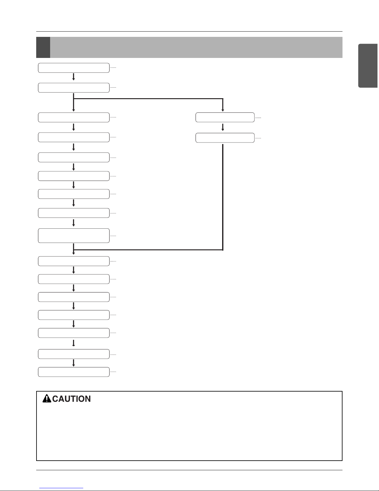
Installation Process
The foundation must be level even
Outside unit foundation work
Avoid short circuits and ensure
sufficient space is allowed for service
Installation of outside unit
Refer to automatic addressing flowchart
Automatic addressing of indoor unit
In the final check for 24hours at 3.8 MPa(38.7 kgf/cm
2
) there must be no drop in pressure.
Airtight test
Multiple core cable must not be used.
(suitable cable should be selected)
Electrical work
(connection circuits and drive circuits)
Make sure no gaps are left where
the insulating materials are joined
Heat insulation work
Make sure airflow is sufficient
Duct work
Adjust to downward gradient
Drain pipe work
Special attention to dryness,
cleanness and tightness
Refrigerant piping work
Check model name to make
sure the fitting is made correctly
Installation of indoor unit
Take account of gradient
of drain piping
Sleeve and insert work
Make relationship between outside, indoor, remote controller, and option connections clear.
(Prepare control circuit diagram)
Preparation of contract drawings
Indicate clearly who is to be responsible for switch settings
Determination of division work
The vacuum pump used must have a capacity of reaching at least 5 torr, more than 1 hour
Vacuum drying
Recharge correctly as calculated in this manual. and record the amount of added refrigerant
Additional charge of refrigerant
Make sure there are no gaps left between the facing materials used on the ceiling
Fit facing panels
Run each indoor unit in turn to make sure the pipe work has been fitted correctly
Test run adjustment
Explain the use of the system as clearly as possible to your customer and make sure all relevant
documentation is in order
Transfer to customer with explanation
Preheat the crank case with the electrical heater for more than 6 hours.
• The above list indicates the order in which the individual work operations are normally carried out but this order may be
varied where local conditions warrants such change.
• The wall thickness of the piping should comply with the relevant local and national regulations for the designed pressure 3.8MPa.
• Since R410A is a mixed refrigerant, the required additional refrigerant must be charged in its liquid state.(If the refrigerant is charged in its gaseous state, its composition changes and the system will not work properly.)
Outside units Information
8 Outside Unit
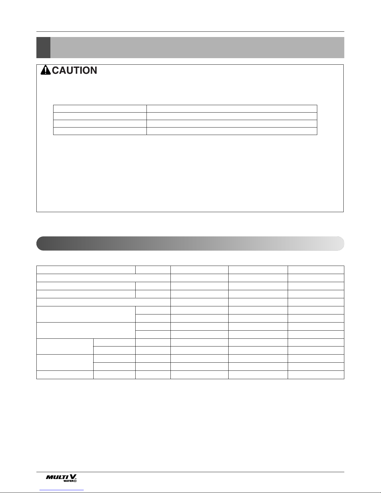
Outside units Information
Power Supply: Outside Unit (3Ø, 208/230V, 60Hz)
n Heat pump
• Ratio of the running Indoor Units to the Outside: Within 10 ~ 100%
• A combination operation over 100% cause to reduce each indoor unit capacity.
n Combination Ration(50~200%)
Notes:
* We can guarantee the operation only within 130% Combination.
If you want to connect more than 130% combination, please contact us and discuss the requirement like below.
1) If the operation of indoor unit is more than 130%, low airflow operation is recommended in all
the indoor units.
2) If the operation of indoor unit is more than 130%, additional refrigerant is needed according to
the Äheadquarter guidance.
3)Over 130%, capacity is same as capacity of 130%, Same remark is valid for power input.
Outside Number Connection Capacity
Single outside units 200%
Double outside units 160%
Triple outside units 130%
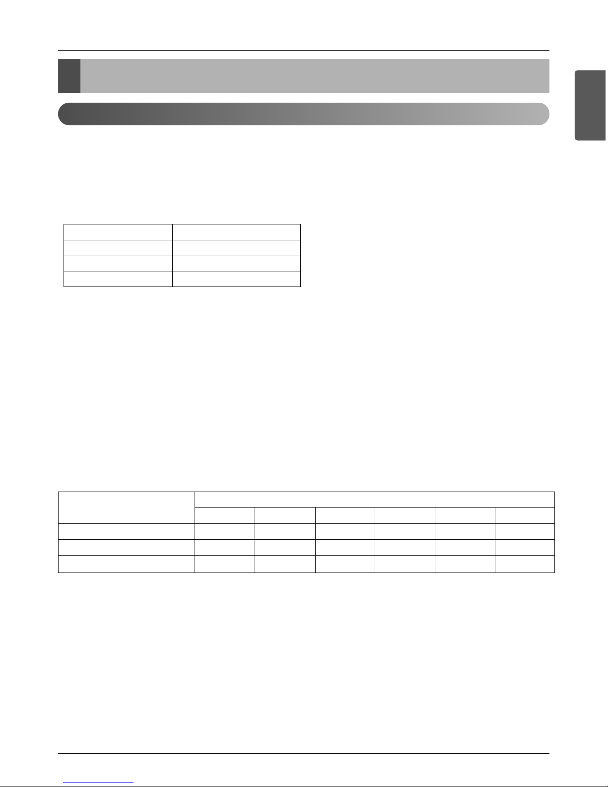
System Capacity HP(Ton)
Model Name
Product Refrigerant Charge (kg(lb))
CF(Correction Factor) (kg(lb))
Maximum Connectable No. of Indoor Units
Net Weight kg
lb
Dimensions(WxHxD) mm
inch
Refrigerant Liquid mm(inch)
Connecting Pipes Gas mm(inch)
Water Inlet mm
Connecting Pipes Outlet mm
Drain Outlet mm(inch)
8(6.5) 16(12.5) 24(19.0)
ARWN072BA2 ARWN144BA2 ARWN216BA2
7.3(16.1) 8.8(19.4) 8.8(19.4) + 7.3(16.1)
---
13 26 39
170 238 238 + 170
374.8 524.7 524.7 + 374.8
772x1,120x547 772x1,120x547 (772x1,120x547) x 2
30.4x44.1x21.5 30.4x44.1x21.5 (30.4x44.1x21.5) x 2
9.52(3/8) 12.7(1/2) 19.05(3/4)
22.2(7/8) 28.58(1 1/8) 34.9(1 3/8)
PT32A PT40A PT40A + PT32A
PT32A PT40A PT40A + PT32A
20(3/4) 20(3/4) 20(3/4)
Outside units Information
Installation Manual 9
ENGLISH
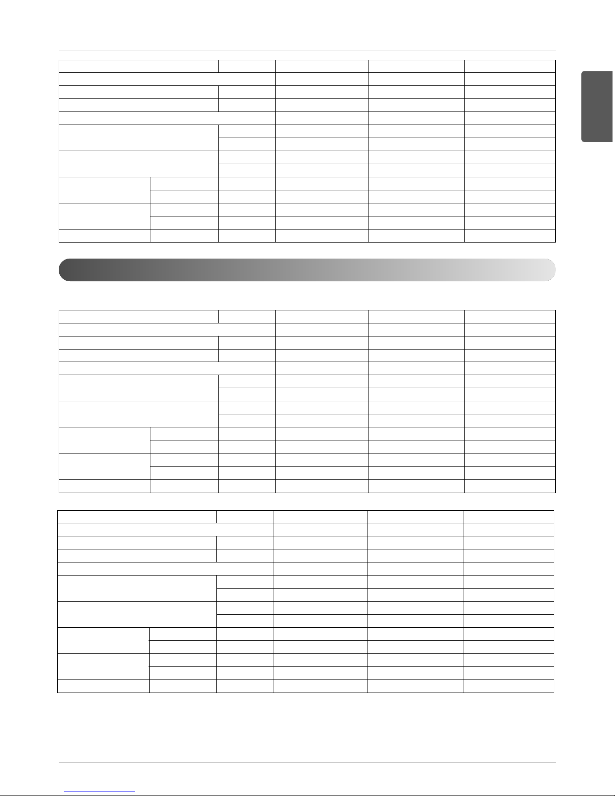
Power Supply: Outside Unit (3Ø, 460V, 60Hz)
n Heat Pump
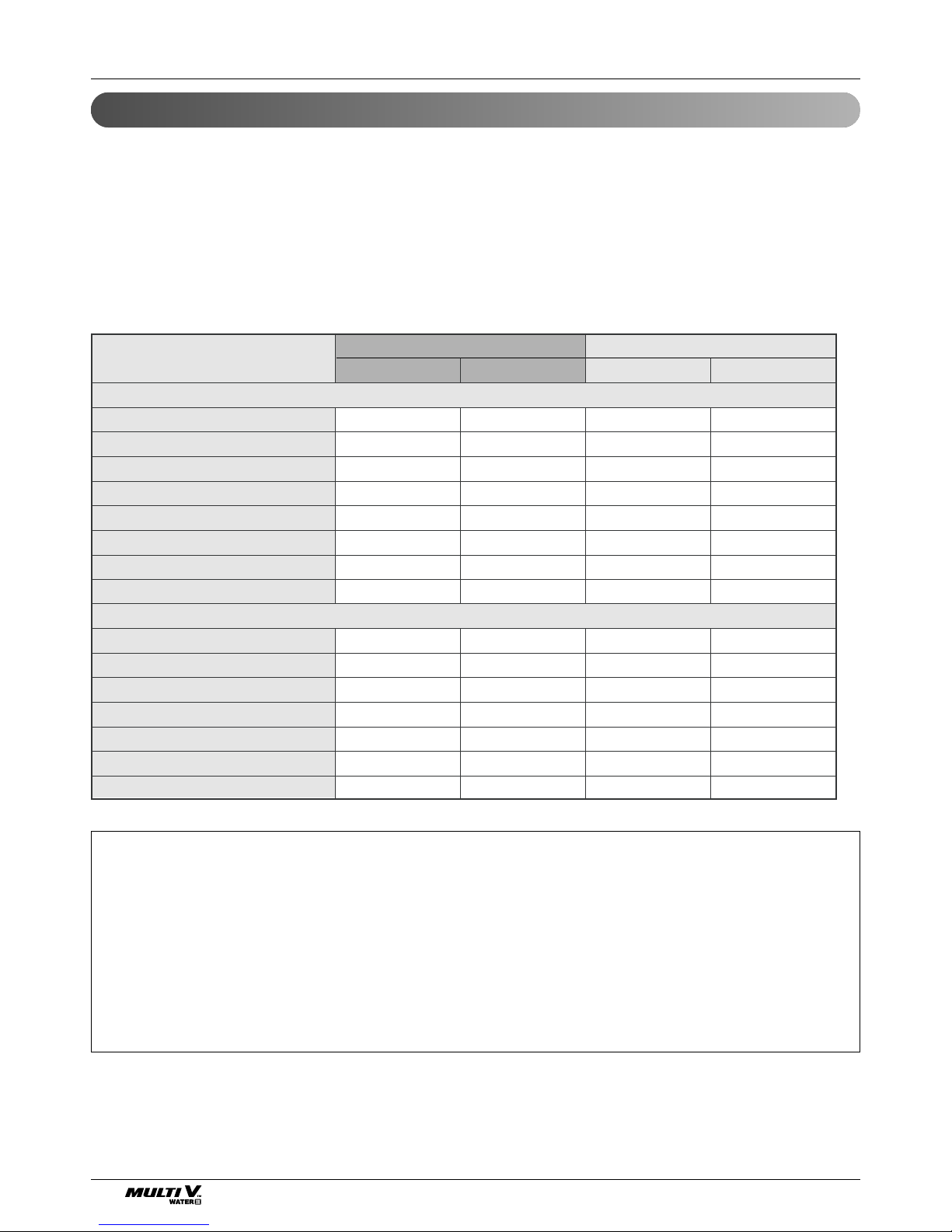
System Capacity HP(Ton)
Model Name
Product Refrigerant Charge (kg(lb))
CF(Correction Factor) (kg(lb))
Maximum Connectable No. of Indoor Units
Net Weight kg
lb
Dimensions(WxHxD) mm
inch
Refrigerant Liquid mm(inch)
Connecting Pipes Gas mm(inch)
Water Inlet mm
Connecting Pipes Outlet mm
Drain Outlet mm(inch)
32(25.5) 40(32.0) 48(38.0)
ARWN288BA2 ARWN360BA2 ARWN432BA2
8.8(19.4) + 8.8(19.4) 8.8(19.4) + 8.8(19.4)+ 7.3(16.1) 8.8(19.4) + 8.8(19.4)+ 8.8(19.4)
---
49 61 64
238 + 238 238 + 238 + 170 238 + 238 + 238
524.7 + 524.7 524.7 + 524.7 + 374.8
524.7 + 524.7 + 524.7
(772x1,120x547) x 2 (772x1,120x547) x 3 (772x1,120x547) x 3
(30.4x44.1x21.5) x 2 (30.4x44.1x21.5) x 3 (30.4x44.1x21.5) x 3
19.05(3/4) 19.05(3/4) 19.05(3/4)
41.3(1 5/8) 41.3(1 5/8) 41.3(1 5/8)
PT40A + PT40A
PT40A + PT40A + PT32A
PT40A + PT40A + PT40A
PT40A + PT40A PT40A + PT40A + PT32A
PT40A + PT40A + PT40A
20(3/4) 20(3/4) 20(3/4)
System Capacity HP(Ton)
Model Name
Product Refrigerant Charge (kg(lb))
CF(Correction Factor) (kg(lb))
Maximum Connectable No. of Indoor Units
Net Weight kg
lb
Dimensions(WxHxD) mm
inch
Refrigerant Liquid mm(inch)
Connecting Pipes Gas mm(inch)
Water Inlet mm
Connecting Pipes Outlet mm
Drain Outlet mm(inch)
10(8.0) 20(16.0) 30(24.0)
ARWN096DA2 ARWN192DA2 ARWN290DA2
7.3(16.1) 8.8(19.4) 8.8(19.4) + 7.3(16.1)
---
16 32 49
170 238 238 + 170
374.8 524.7 524.7 + 374.8
772x1,120x547 772x1,120x547 (772x1,120x547) x 2
30.4x44.1x21.5 30.4x44.1x21.5 (30.4x44.1x21.5) x 2
9.52(3/8) 12.7(1/2) 19.05(3/4)
22.2(7/8) 28.58(1 1/8) 34.9(1 3/8)
PT32A PT40A PT40A + PT32A
PT32A PT40A PT40A + PT32A
20(3/4) 20(3/4) 20(3/4)
System Capacity HP(Ton)
Model Name
Product Refrigerant Charge (kg(lb))
CF(Correction Factor) (kg(lb))
Maximum Connectable No. of Indoor Units
Net Weight kg
lb
Dimensions(WxHxD) mm
inch
Refrigerant Liquid mm(inch)
Connecting Pipes Gas mm(inch)
Water Inlet mm
Connecting Pipes Outlet mm
Drain Outlet mm(inch)
40(32.0) 50(40.0) 60(48.0)
ARWN390DA2 ARWN480DA2 ARWN580DA2
8.8(19.4) + 8.8(19.4) 8.8(19.4) + 8.8(19.4)+ 7.3(16.1) 8.8(19.4) + 8.8(19.4)+ 8.8(19.4)
---
64 64 64
238 + 238 238 + 238 + 170 238 + 238 + 238
524.7 + 524.7 524.7 + 524.7 + 374.8
524.7 + 524.7 + 524.7
(772x1,120x547) x 2 (772x1,120x547) x 3 (772x1,120x547) x 3
(30.4x44.1x21.5) x 2 (30.4x44.1x21.5) x 3 (30.4x44.1x21.5) x 3
19.05(3/4) 19.05(3/4) 19.05(3/4)
41.3(1 5/8) 41.3(1 5/8) 41.3(1 5/8)
PT40A + PT40A PT40A + PT40A + PT32A PT40A + PT40A + PT40A
PT40A + PT40A PT40A + PT40A + PT32A
PT40A + PT40A + PT40A
20(3/4) 20(3/4) 20(3/4)
Environment-friendly Alternative Refrigerant R410A
10 Outside Unit
Select the Best Location
Select space for installing outside unit, which will meet the following conditions:
• No direct thermal radiation from other heat sources
• No possibility of annoying neighbors by noise from unit
• No exposition to strong wind
• With strength which bears weight of unit
• Note that drain flows out of unit when heating
• With space for air passage and service work shown next
• Because of the possibility of fire, do not install unit to the space where generation, inflow, stagnation, and
leakage of combustible gas is expected.
• Avoid unit installation in a place where acidic solution and spray (sulfur) are often used.
• Do not use unit under any special environment where oil, steam and sulfuric gas exist.
• It is recommended to fence round the outside unit in order to prevent any person or animal from accessing the
outside unit.
• This product is prohibited for outdoor installation.
• Select installation location considering following conditions to avoid bad condition when additionally performing
defrost operation.
1. Install the outside unit at a place well ventilated and having a lot of sunshine in case of installing the product
at a place with a high humidity in winter (neare beach, coast, lake, etc).
(Ex) Rooftop where sunshine always shines.
2. Performance of heating will be reduced and preheat time of the indoor unit may be lengthened in case of
installing the outside unit in winter at following location:
(1) Shade position with a narrow space
(2) Location with much moisture in neighboring floor.
(3) Location with much humidity around.
(4) Location where water gathers since the floor is not even.
• The refrigerant R410A has the property of higher operating pressure in comparison with R22.
Therefore, all materials have the characteristics of higher resisting pressure than R22 ones and this characteristic should be also considered during the installation.
R410A is an azeotrope of R32 and R125 mixed at 50:50, so the ozone depletion potential (ODP) of R410A is
0. These days the developed countries have approved it as the environment-friendly refrigerant and encouraged to use it widely to prevent environment pollution.
Environment-friendly Alternative Refrigerant R410A
CAUTION:
• The wall thickness of the piping should comply with the relevant local and national regulations for the designed
pressure 3.8MPa
• Since R410A is a mixed refrigerant, the required additional refrigerant must be charged in its liquid state.
If the refrigerant is charged in its gaseous state, its composition changes and the system will not work properly.
• Do not place the refrigerant container under the direct rays of the sun to prevent it from exploding.
• For high-pressure refrigerant, any unapproved pipe must not be used.
• Do not heat pipes more than necessary to prevent them from softening.
• Be careful not to install wrongly to minimize economic loss because it is expensive in comparison with R22.

Installation space
Installation Manual 11
ENGLISH
Installation space
Individual Installation
Collective / Continuous Installation
Required the minimum space as shown below for installation and
check. If the space is not fit on this drawing, consult with LG.
Space required for collective installation and continuous installation as shown below considering passage for air
and people.
: Service area
* In case of the water pipe passing side product, please make sufficient service place to avoid occurring
between water pipe and product side.
: Service area
20(3/4)
100(5-7/8)
350(13-25/32)
772(30-13/32)
H-Beam Support
[Unit: mm(inch)]
600(23-5/8)
547(21-17/32)
1,120(44-3/32)
100(5-7/8)
100(5-7/8)
20(3/4)
<Front View>
Water pipe
installation
space
<Top View>
Product
(Outside unit)
Service area
(Front)
[Unit: mm(inch)]
350(13-25/32)
20(3/4)
350(13-25/32)
772(30-13/32) 772(30-13/32)
100(5-7/8) 100(5-7/8)
600(23-5/8)
547(21-17/32)
20(3/4)
<Top view>
Product
(Outside unit)
Service area
(Front)
Product
(Outside unit)
Service area
(Front)
[Unit: mm(inch)]
350(13-25/32)350(13-25/32)
100(5-7/8) 100(5-7/8)
772(30-13/32)
20(3/4)
772(30-13/32)
100(5-7/8)
350(13-25/32)
772(30-13/32)
600(23-5/8) 547(21-17/32)
20(3/4)
<Top view>
Product
(Outside unit)
Service area
(Front)
Product
(Outside unit)
Service area
(Front)
Product
(Outside unit)
Service area
(Front)
12 Outside Unit
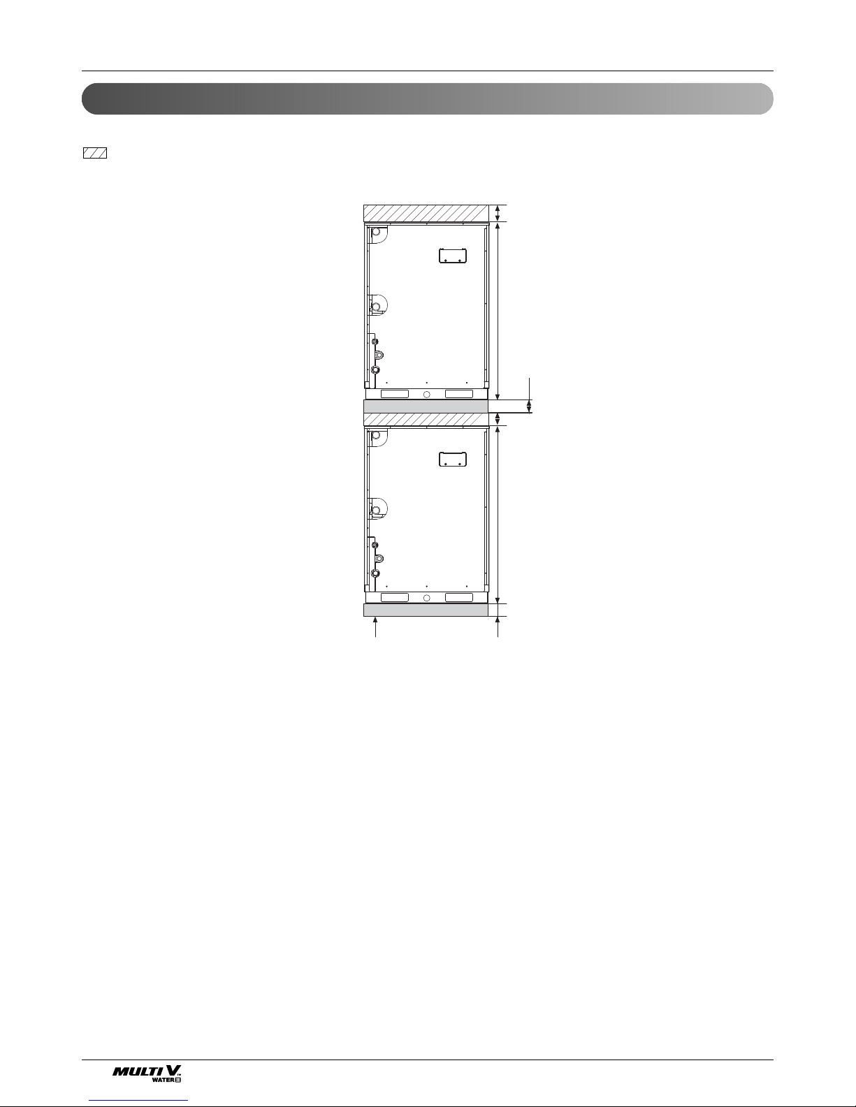
Two Layer Installation
Space required for two layer installation as shown below considering passage for air and people.
: Service area
H-Beam Support
1,120(44-3/32)
100(5-7/8)
100
(5-7/8)
100(5-7/8)
<Front View>
[Unit: mm(inch)]
1,120(44-3/32)
100(5-7/8)
Installation space
Installation Manual 13
ENGLISH
Installation space
Water control
Water control
• Keep the water temperature between 10~45°C(50~113°F). Other it may cause the breakdown.
- Standard water supply temperature is 30°C(86°F) for Cooling and 20°C(68°F) for heating.
• Properly control the water velocity. Otherwise it may cause the noise, pipe vibration or pipe contraction, expansion
according to the temperature. Use the same water pipe size connected with the product or more.
• Refer to the water source pipe diameter and water velocity table below. As the water velocity is fast, air bubble will
increase.
• Be careful of the water purity control. Otherwise it may cause the breakdown due to water pipe corrosion.
(Refer to 'Standard Table for Water Purity Control')
• In case the water temperature is above 40°C(104°F), it is good to prevent the corrosion by adding the anticorrosive
agent.
• Install the pipe, valve and gauge sensor in the space where it is easy to maintain. Install the water valve in the low
position for drain, if required.
• Be careful not to let air in. If so, the water velocity will be unstable in the circulation, pump efficiency will also
decrease and may cause the piping vibration. Therefore, install the air purge where it may generate the air.
• Choose the following anti freezing methods. Otherwise, it will be dangerous for the pipe to break in the winter.
- Circulate the water with the pump before dropping the temperature.
- Keep the normal temperature by boiler.
- When the cooling tower is not operated for a long time, drain the water in the cooling tower.
- Use an anti-freeze.
- Refer to the additive amount about freezing temperature as in the table given below.
• In addition to anti freeze, it may cause the change of the pressure in the water system and the low performance of
the product.
• Make sure to use the closed cooling type tower.
When applying the open type cooling tower, use a 2
nd
heat exchanger to make the water supply system a closed
type system.
Diameter [mm(inch)] Velocity range (m/s)
< 50(1-31/32) 0.6 ~ 1.2
50(1-31/32) ~ 100(5-7/8) 1.2 ~ 2.1
100100(5-7/8) < 2.1 ~ 2.7
Minimum temperature for anti freezing [°C(°F)]
0 -5(23) -10(14) -15(5) -20(-4) -25
Ethylene glycol (%) 0 12 20 30 - -
Propylene glycol (%) 0 17 25 33 - -
Methanol (%) 0 6 12 16 24 30
Anti freeze type
14 Outside Unit
Standard table for water purity control
The water may contain many foreign substances and hence may influence the performance and lifetime of the product due to the corrosion of the condenser and water pipe. (Use water source that complies with the below standard
table for water purity control.)
If you use water supply other than the tap water to supply the water for the cooling tower, you must do a water quality
inspection.
• If you use the closed cooling tower, the water quality must be controlled in accordance with the following standard
table.
If you do not control the water quality in accordance with the following standard water quality table, it can cause performance deterioration to the air conditioner and severe problem to the product
[Reference]
(1) The "O" mark for corrosion and scale means that there is possibility of occurrence.
(2) When the water temperature is 40°C or above or when uncoated iron is exposed to the water, it can result in corro-
sion. Therefore adding anti-corrosion agent or removing the air can be very effective.
(3) In case of using the closed type cooling tower, the cooling water and supplementing water must satisfy the water quality criteria of closed type system in the table.
(4) Supplementing water and supplied water must be supplied with tap water, industrial water and underground water
excluding filtered water, neutral water, soft water etc.
(5) 15 items in the table are general causes of corrosion and scale.
Items
pH(25°C)
Conductivity[25°C](mS/m)
Chlorine ion(mg CI-/l)
Sulfuric acid ion(mg SO
2
-
/l)
Acid demand[pH 4.8] (mg SiO2/l)
Total hardness(mg SiO
2/l)
Ca hardness(mg CaCO
3/l)
Ion silica(mg SiO2/l)
Fe(mg Fe/l)
Copper(mg Cu/l)
Sulfuric acid ion(mg S2/l)
Ammonium ion(mg NH4/l)
Residual chlorine(mg Cl/l)
Free carbon dioxide(mg CO2/l)
Stability index
7.0~8.0
Below 30
Below 50
Below 50
Below 50
Below 70
Below 50
Below 30
Below 1.0
Below 1.0
Must not be detected
Below 0.3
Below 0.25
Below 0.4
-
Below 0.3
Below 0.1
Must not be detected
Below 0.1
Below 0.3
Below 4.0
-
7.0~8.0
Below 30
Below 50
Below 50
Below 50
Below 70
Below 50
Below 30
O
O
O
O
-
-
-
-
O
O
O
O
O
O
O
O
-
-
-
-
-
O
O
O
O
O
O
O
O
Closed type
Basic Item
Reference Item
Effect
Circulating water Supplemented water Corrosion Scale
4
+
Water control
Installation Manual 15
ENGLISH
Lifting method
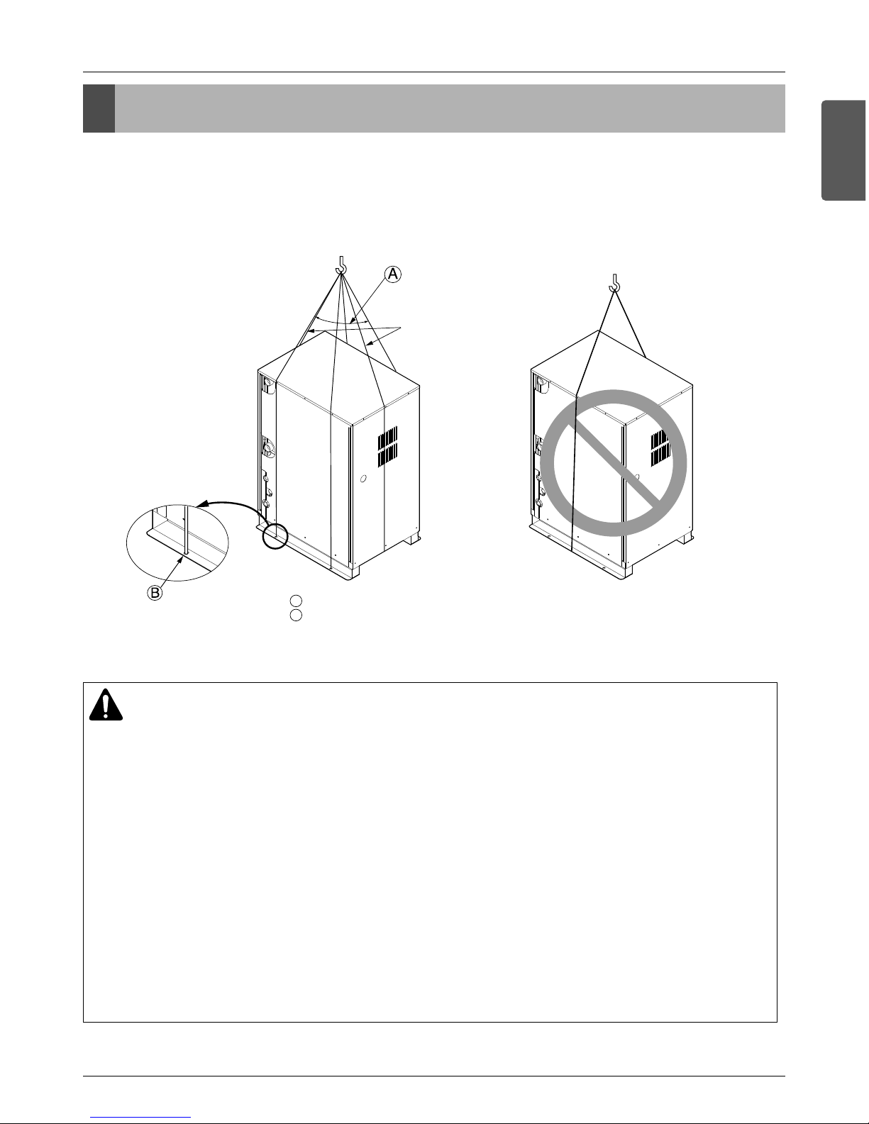
Lifting method
• When carrying the suspended, unit pass the ropes under the unit and use the two suspension points each at
the front and rear.
• Always lift the unit with ropes attached at four points so that impact is not applied to the unit.
• Attach the ropes to the unit at an angle of 40° or less.
40° or less
Rope supporter
A
B
Sub line
CAUTION
Be very careful while carrying the product.
• Do not have only one person carry product if it is more than 20kg.
• PP bands are used to pack some products. Do not use them as a mean for transportation because they
are dangerous.
• Do not touch heat exchanger fins with your bare hands. Otherwise you may get a cut in your hands.
• Tear plastic packaging bag and scrap it so that children cannot play with it. Otherwise plastic packaging
bag may suffocate children to death.
• When carrying in Outside Unit, be sure to support it at four points. Carrying in and lifting with 3-point
support may make Outside Unit unstable, resulting in a fall.
• Use 2 belts of at least 8 m long.
• Place extra cloth or boards in the locations where the casing comes in contact with the sling to prevent
damage.
• Hoist the unit making sure it is being lifted at its center of gravity.
16 Outside Unit
Installation
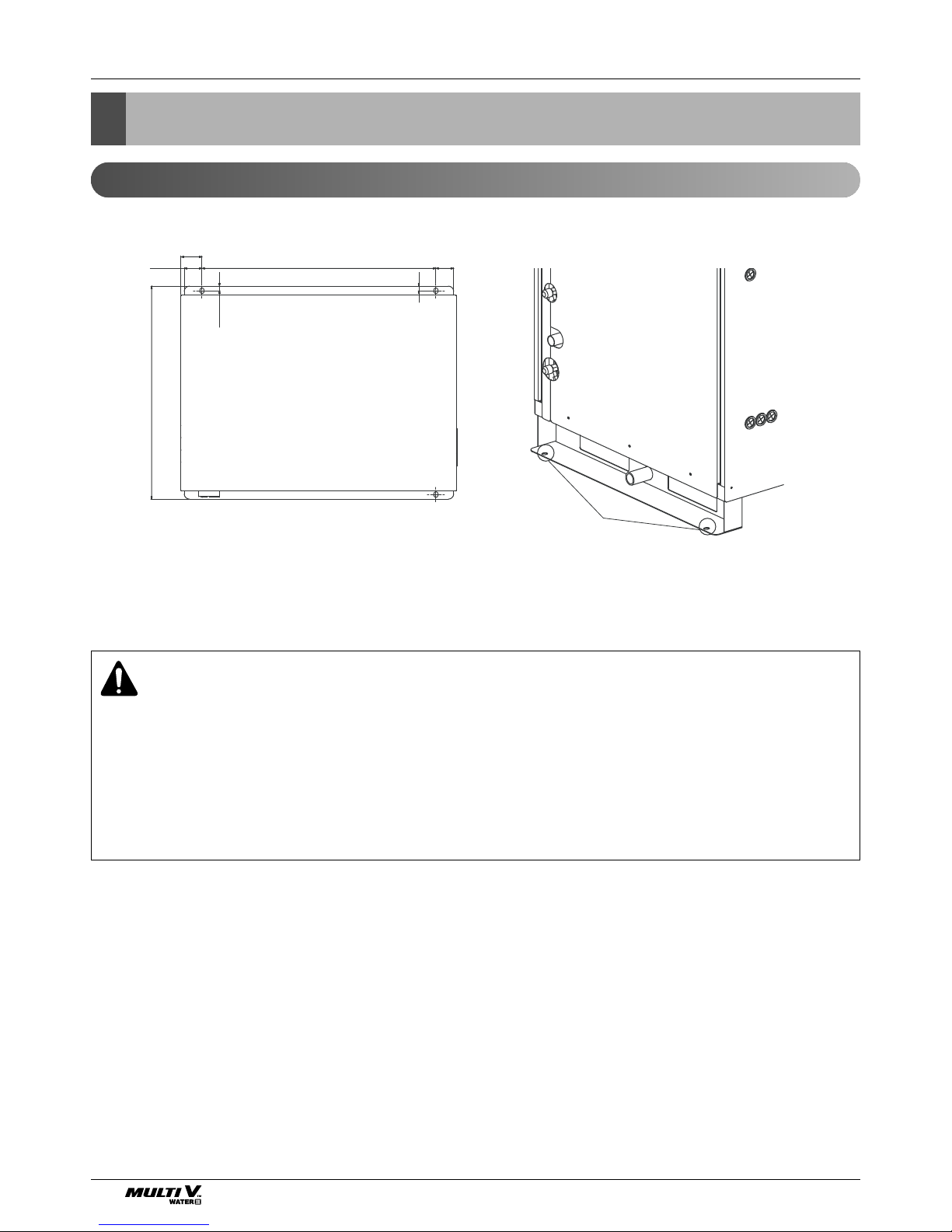
Location of anchor bolt
The location of
anchor bolt
59(2-5/16)
50(2)
13(1/2)
599(23-19/32)
658(25-29/32)
[Unit: mm(inch)]
Installation
WARNING
• Be sure to install unit in a place strong enough to withstand its weight.
Any lack of strength may cause unit to fall down, resulting in a personal injury.
• Have installation work in order to protect against a strong wind and earthquake. Any installation
deficiency may cause unit to fall down, resulting in a personal injury.
• Especially take care for support strength of the floor surface, water drain processing (processing of
water flown out from the outside unit during operation) and paths of the pipe and wiring when making a base support.
Installation Manual 17
ENGLISH
Installation
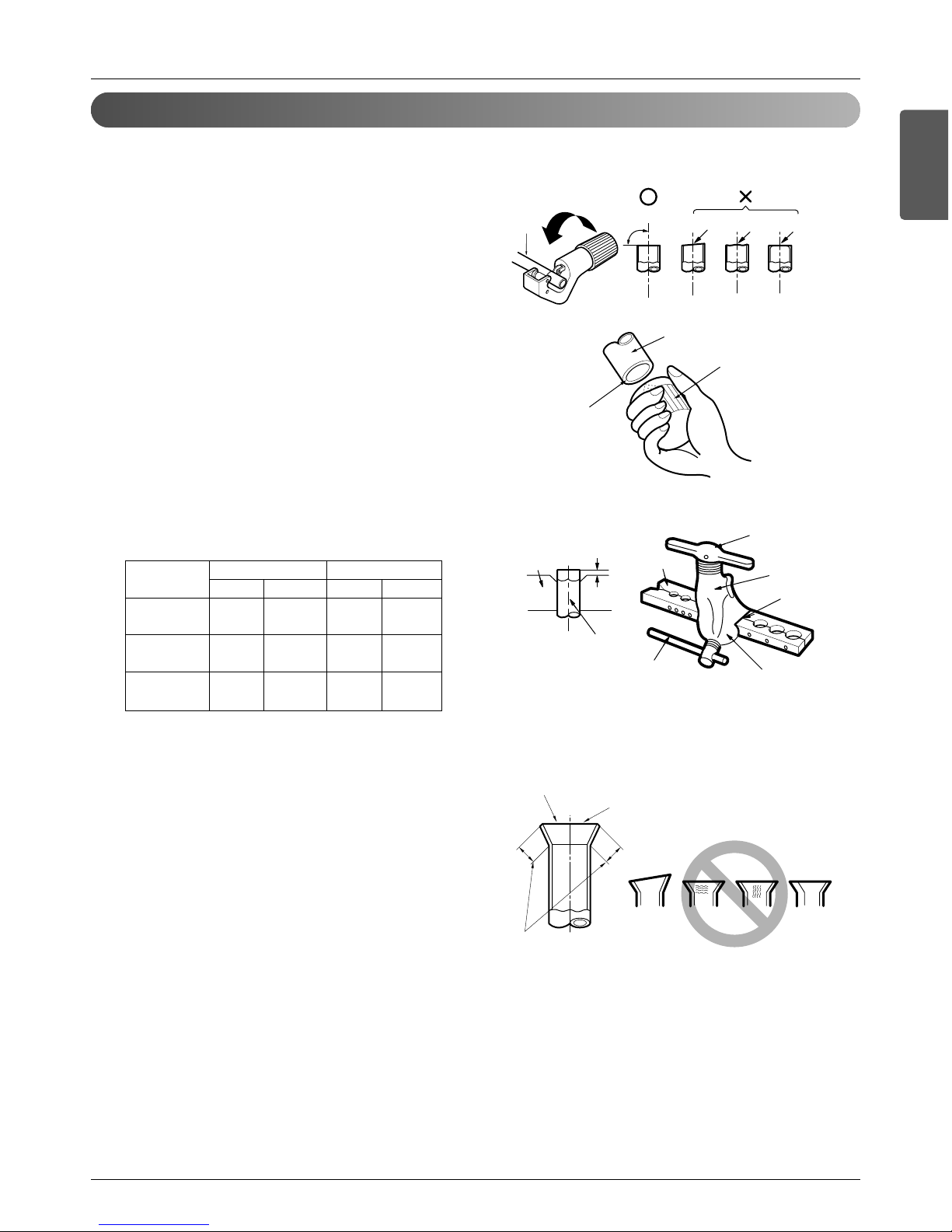
Preparation of Piping
1) Cut the pipes and the cable.
n Use the accessory piping kit or the pipes purchased
locally.
n Measure the distance between the indoor and the out-
side unit.
n Cut the pipes a little longer than measured distance.
n Cut the cable 1.5m longer than the pipe length.
2) Burrs removal
n Completely remove all burrs from the cut cross section
of pipe/tube.
n Put the end of the copper tube/pipe to downward direc-
tion as you remove burrs in order to avoid to let burrs
drop in the tubing.
3) Flaring work
n Carry out flaring work using flaring tool as shown below.
Firmly hold copper tube in a bar(or die) as indicated
dimension in the table above.
4) Check
n Compare the flared work with figure below.
n If flare is noted to be defective, cut off the flared section
and do flaring work again.
Main cause of gas leakage is defect in flaring work. Carry out correct flaring work in the following procedure.
Copper
tube
90°
Slanted Uneven Rough
Pipe
Reamer
Point down
Bar
Copper pipe
Clamp handle
Red arrow mark
Cone
Yoke
Handle
Bar
"A"
Inclined
Inside is shining without scratches.
Smooth all round
Even length
all round
Surface
damaged
Cracked Uneven
thickness
= Improper flaring =
[Unit: mm(inch)]
Pipe " A "
Gas Liquid Gas
Liquid
≤
5.6(19,100) 12.7(1/2) 6.35(1/4)
1.6~1.8 1.1~1.3
(0.63~0.71) (0.43~0.51)
<16.0(54,600) 15.88(5/8) 9.52(3/8)
1.6~1.8 1.5~1.7
(0.63~0.71) (0.59~0.67)
≤
22.4(76,400) 19.05(3/4) 9.52(3/8)
1.9~2.1 1.5~1.7
(0.75~0.83) (0.59~0.67)
Indoor unit
[kW(Btu/h]
18 Outside Unit
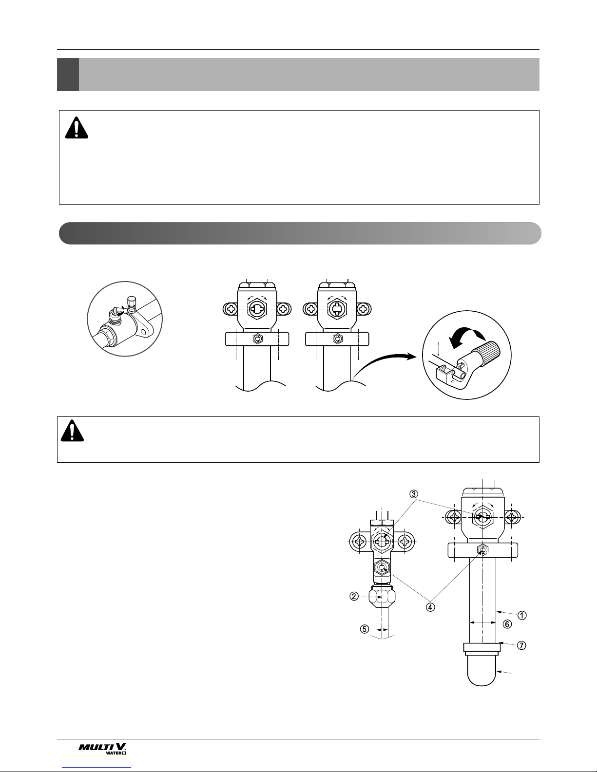
Installation
1. Remove the cap and turn the valve counter clockwise with the hexagon wrench.
2. Turn it until the shaft stops.
Do not apply excessive force to the shutoff valve. Doing so may break the valve body, as the valve is not a
backseat type. Always use the special tool.
3. Make sure to tighten the cap securely.
1. Remove the cap and turn the valve clockwise with the hexagon wrench.
2. Securely tighten the valve until the shaft contacts the main body seal.
3. Make sure to tighten the cap securely.
* For the tightening torque, refer to the table on the below.
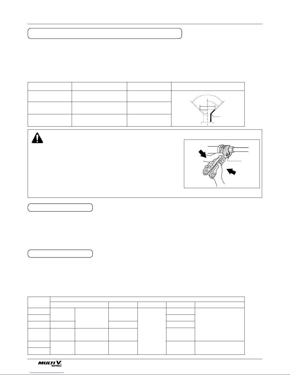
Precautions when connecting pipes
• See the following table for flare part machining dimensions.
• When connecting the flare nuts, apply refrigerant oil to the inside and outside of the flares and turn them three
or four times at first. (Use ester oil or ether oil.)
• See the following table for tightening torque.(Applying too much torque may cause the flares to crack.)
• After all the piping has been connected, use nitrogen to perform a gas leak check.
Tightening torque
Union
CAUTION
• Always use a charge hose for service port connection.
• After tightening the cap, check that no refrigerant leaks are
present.
• When loosening a flare nut, always use two wrenches in
combination, When connecting the piping, always use a spanner
and torque wrench in combination to tighten the flare nut.
• When connecting a flare nut, coat the flare(inner and outer faces)
with oil for R410A(PVE) and hand tighten the nut 3 to 4 turns as
the initial tightening.
Opening shutoff valve
Closing shutoff valve
FLARE SHAPE and FLARE NUT TIGHTENING TORQUE
Shutoff
valve size
Ø6.4
Ø9.5
Ø12.7
Ø15.9
Ø22.2
Ø25.4
13.5-16.5
18-22
14-17
33-39
50-60
62-75
23-27
13.5-16.5
5.4-6.6
Hexagonal
wrench 4mm
Hexagonal
wrench 6mm
Hexagonal
wrench 10mm
8.1-9.9
27-33 36-44
-
11.5-13.9
22-28-
Tightening torque N-m(Turn clockwise to close)
Shaft(valve body)
Gas line piping attached to unit
Cap(Valve lid) Service port Flare nut
90°
±2
45
°
±
2
A
R=0.4~0.8
pipe size tightening torque(Ncm) A(mm) flare shape
Ø9.5 3270-3990 12.8-13.2
Ø12.7 4950-6030 16.2-16.6
Ø15.9 6180-7540 19.3-19.7
Installation Manual 19
ENGLISH
Installation
1. Use the heat insulation material for the refrigerant piping which has an excellent heat-resistance (over
120°C).
2. Precautions in high humidity circumstance:
This air conditioner has been tested according to the
"ISO Conditions with Mist" and confirmed that there is
not any default. However, if it is operated for a long
time in high humid atmosphere (dew point temperature: more than 23°C), water drops are liable to fall. In
this case, add heat insulation material according to the
following procedure:
• Heat insulation material to be prepared... EPDM
(Ethylene Propylene Diene Methylene)-over 120°C
the heat-resistance temperature.
• Add the insulation over 10mm thickness at high humidity environment.
Indoor unit
Thermal insulator
(accessory)
Fastening band
(accessory)
Refrigerant piping
HEAT INSULATION
20 Outside Unit
Refrigerant piping installation
WARNING
After completing work, securely tighten both service ports and caps so that gas does not leak.
Refrigerant piping installation
WARNING
Always use extreme care to prevent the refrigerant gas (R410A) from leakage while using fire or
flame. If the refrigerant gas comes in contact with the flame from any source, such as a gas stove, it
breaks down and generates a poisonous gas which can cause gas poisoning. Never perform brazing
in an unventilated room. Always conduct an inspection for gas leakage after installation of the refrigerant piping has been completed.
① Pipe joint (auxiliary parts): Securely perform brazing with
a nitrogen blow into the service valve port.(Releasing
pressure : 0.02 MPa or less)
② Flare nut: Loose or tighten flare nut by using the wrench
with both ends. Coat the flare connection part with oil for
the compressor.
③ Cap: Remove caps and operate valve, etc. After opera-
tion, always reattach caps (tightening torque of valve
cap: 25Nm (250kg-cm) or more). (Don't remove the
internal part of the port)
④ Service port: Make the refrigerant pipe vacuum and
charge it using the service port. Always reattach caps
after completing work (tightening torque of service cap:
14Nm (140kg-cm) or more).
⑤ Liquid pipe
⑥ Gas pipe
⑦ Elbow joint (field supply)
Cautions in pipe connection/valve operation
Open status when both the pipe and
the valve are in a straight line.
Cut both the pipe and the valve with a
cutter to suit the length
(Don't cut the length of less than 70mm)
CLOSE OPEN
Elbow
Ball Valve(Gas Pipe)
Ball Valve(Liquid Pipe)
Installation Manual 21
ENGLISH
Refrigerant piping installation
Slave
Outside Unit
Master
Outside Unit
Slave1
Outside
Unit
Slave2
Outside
Unit
Main
Outside Unit
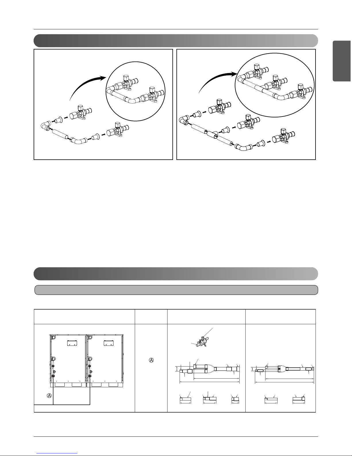
1) For the high/low pressure common pipe, connect both master outside unit and slave outside units to the pipe by using
elbows.
2) For cutting the pipe, connect the high/low pressure common pipe after removing burrs, dusts and foreign material within
the pipe. Otherwise, the product may not operate due to sludge within the pipe.
3) For the working part leakage test, apply the nitrogen gas pressure of 3.8MPa (38.7kgf/cm
2
).
4) The vacuum criteria is to maintain the vacuum level to less than 5 Torr 1 hour after reaching 5 Torr. (Execute the vacuum
work again when it is below the criteria.)
5) Open the valve with the hexagon wrench.
Connecting
branch pipe
Combination specification Gas pipe Liquid pipe
Do not cut for
70mm or less
Execute the welding
while pouring
nitrogen
ARCNN20
[mm(inch)]
401(15-25/32)
331(13-1/32)
24
(31/32)
80(3-5/32)
73(2-7/8)
O.D12.7(1/2)
I.D12.7(1/2)
I.D12.7(1/2)
I.D12.7(1/2)
I.D9.52(3/8)
I.D9.52(3/8)
I.D15.88(5/8)
I.D19.05(3/4)
I.D19.05(3/4)
I.D22.2(7/8)
473(18-5/8)
363(14-9/32)
38
(1-1/2)
I.D28.58(1-1/8)
O.D28.58(1-1/8)
I.D28.58(1-1/8)
I.D28.58(1-1/8)
I.D19.05(3/4)
I.D19.05(3/4)
I.D19.05(3/4)
I.D15.88(5/8)
I.D31.8(1-1/4)
I.D34.9(1-3/8)
O.D34.9(1-3/8)
75(2-15/16) 83(3-9/32)
1.
8
3
.D.I
115(4-17/32)
I.D22.2(7/8)
I.D22.2(7/8)
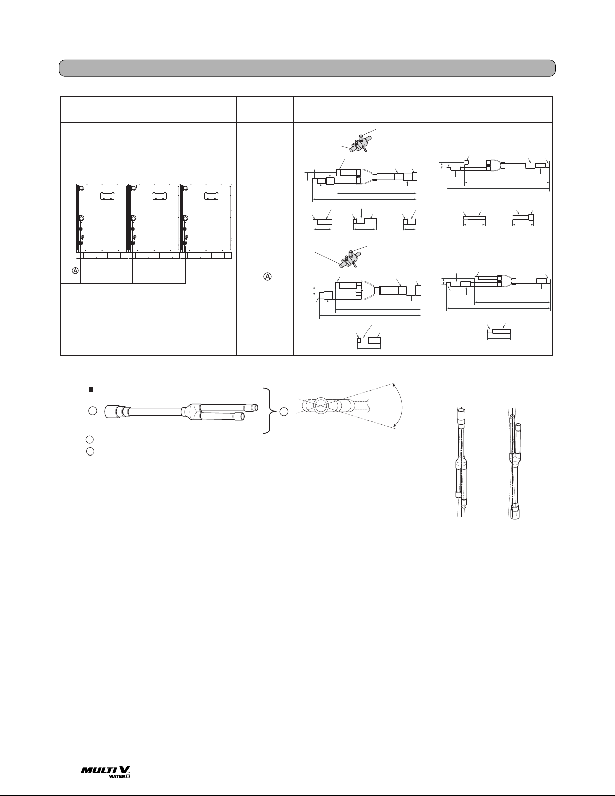
2 Outside Units 3 Outside Units
Connection of High/Low Pressure Common pipe
2 outside units
Connection of Outside units
22 Outside Unit
Refrigerant piping installation
3 Outside Units
Y branch
A
B
To outside unit
To branch piping or indoor unit
A
B
Facing
upwards
Facing
downwards
Within 3 Within 3
Viewed from point A
in direction of arrow
Within +/- 10
Connecting
branch pipe
Combination specification Gas pipe Liquid pipe
ARCNN20
ARCNN30
Don't cut the pipe less than
70mm
Blow nitrogen while
brazing
I.D38.1(1-1/2)
I.D38.1(1-1/2)
I.D34.9(1-3/8)
Don't cut the pipe less than
70mm
Blow nitrogen while
brazing
[mm(inch)]
401(15-25/32)
331(13-1/32)
24
(31/32)
80(3-5/32)
73(2-7/8)
73(2-7/8)
O.D12.7(1/2)
I.D12.7(1/2)
I.D12.7(1/2)
I.D12.7(1/2)
I.D12.7(1/2)
I.D12.7(1/2)
I.D9.52(3/8)
O.D12.7(1/2)I.D9.52(3/8)
I.D9.52(3/8)
I.D15.88(5/8)
I.D15.88(5/8)
I.D19.05(3/4)
I.D19.05(3/4)
I.D19.05(3/4)
I.D22.2(7/8)
I.D22.2(7/8)
440(17-5/16)
370(14-9/16)
45
(25/32)
I.D
41.3(1-5/8)
397(15-5/8)
289(11-3/8)
24
(31/32)
473(18-5/8)
363(14-9/32)
38
(1-1/2)
I.D28.58(1-1/8)
O.D28.58(1-1/8)
I.D28.58(1-1/8)
I.D28.58(1-1/8)
I.D28.58(1-1/8)
I.D28.58(1-1/8)
I.D19.05(3/4)
I.D19.05(3/4)
I.D19.05(3/4)
I.D19.05(3/4)
I.D15.88(5/8)
I.D31.8(1-1/4)
I.D34.9(1-3/8)
O.D34.9(1-3/8)
I.D34.9(1-3/8)
75(2-15/16) 83(3-9/32)
115(4-17/32)
115(4-17/32)
I.D22.2(7/8)
O.D28.58(1-1/8)
I.D19.05(3/4)
I.D22.2(7/8)
I.D22.2(7/8)
Installation Manual 23
ENGLISH
Refrigerant piping installation
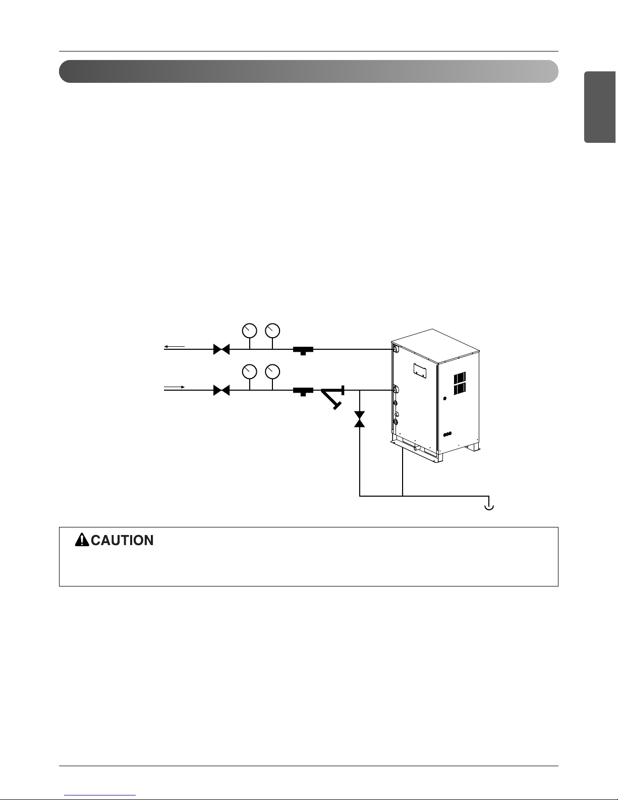
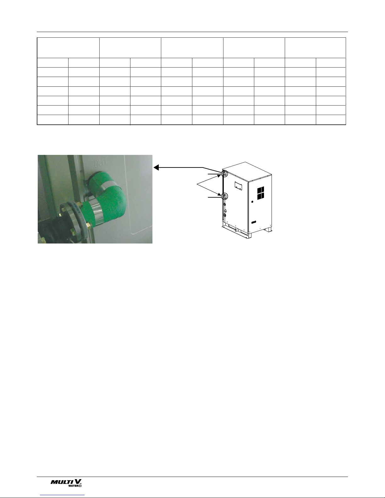
1) Water pipe system diagram
• The water pressure resistance of the water pipe system of this product is 1.98MPa
• When the water pipe passes indoors, make sure to execute heat insulation on the pipe so that water drops do not form on
the outer side of the water pipe.
• The size of the drain pipe must be equal to or larger than the diameter of the connecting product.
- Always install a trap so that the drained water does not back flush.
• Always install a strainer (50Mesh or above) at the entrance of the water pipe. (When sand, trash, rusted pieces get mixed
into the water supply, it can cause problems to the product due to blocking)
- If On/Off valve is applied, by interlocking with outside unit, it can save the energy consumption of pump by blocking the
water supply to the outside unit not operating. Select appropriate valve and install on site if necessary.
• Install a pressure gauge and temperature gauge at the inlet and outlet of the water pipe.
• Flexible joints must be installed not to cause any leakage from the vibration of pipes.
• Install a service port to clean the heat exchanger at the each end of the water inlet and outlet.
• For the components of the water pipe system, always use components above the designed water pressure.
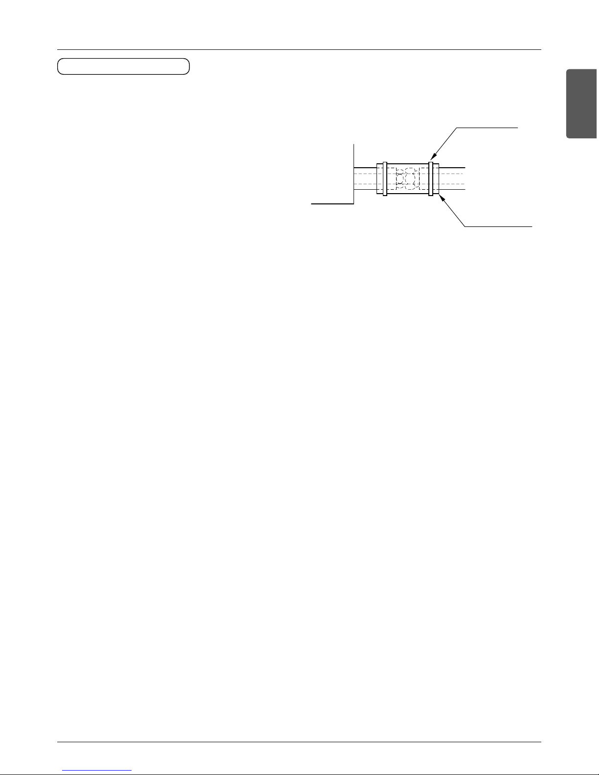
2) Water pipe connection
• The water pipe should be the same size of the connection on the product or more.
• If necessary install the insulation material in the water pipe inlet/outlet to prevent water drop, freeze and to save energy.
(Use the above 20mm thickness PE insulation material.)
• Tightly connect the socket to the water pipe refer to below table for recommended specification.
(Too much torque may cause the damage of the facility.)
Water pipe
outlet
Gate valve
Gate valve
Service port
Pressure gauge
Temperature gauge
Service port
Strainer
Drain line
Condensed
water drain
Water pipe
Inlet
Do not directly connect the drain outlet to the water pipe outlet.
(It can cause problems to the product.)
Installation of water pipe
24 Outside Unit
Water pipe
connection
Water pipe inlet
Water pipe outlet
mm inch (kN) (kgf) (kN) (kgf) (N.m) (kgf.m)(N.m) (kgf.m)
12.7 1/2 3.5 350 2.5 250 20 2 35 3.5
19.05 3/4 12 1,200 2.5 250 20 2 115 11.5
25.4 1 1 1.2 1,120 4 400 45 4.5 155 15.5
31.8 1 1/4 14.5 1,450 6.5 650 87.5 8.75 265 26.5
38.1 1 1/2 16.5 1,700 9.5 950 155 16 350 35.5
50.8 2 21.5 2,200 13.5 1,400 255 26 600 61
Pipe thickness Shear stress Tensile stress Bending moment Torque
Refrigerant piping installation
Installation Manual 25
ENGLISH
Product protection device
Device protection unit
Strainer on water pipe
To protect the water cooling type product, you must install a strainer with 50 mesh or more on the heat water supply pipe.
If not installed, it can result in damage of heat exchanger by the following situation.
1. Heat water supply within the plate type heat exchanger is composed of multiple small paths.
2. If you do not use a strainer with 50 mesh or more, alien particles can partially block the water paths.
3. When running the heater, the plate type heat exchanger plays the role of the evaporator, and at this time, the temperature of the
coolant side drops to drop the temperature of the heat water supply, which can result in icing point in the water paths.
4. And as the heating process progresses, the water paths can be partially frozen to lead to damage in plate type heat exchanger.
5. As a result of the damage of the heat exchanger from the freezing, the coolant side and the heat water source side will be mixed
to make the product unusable.
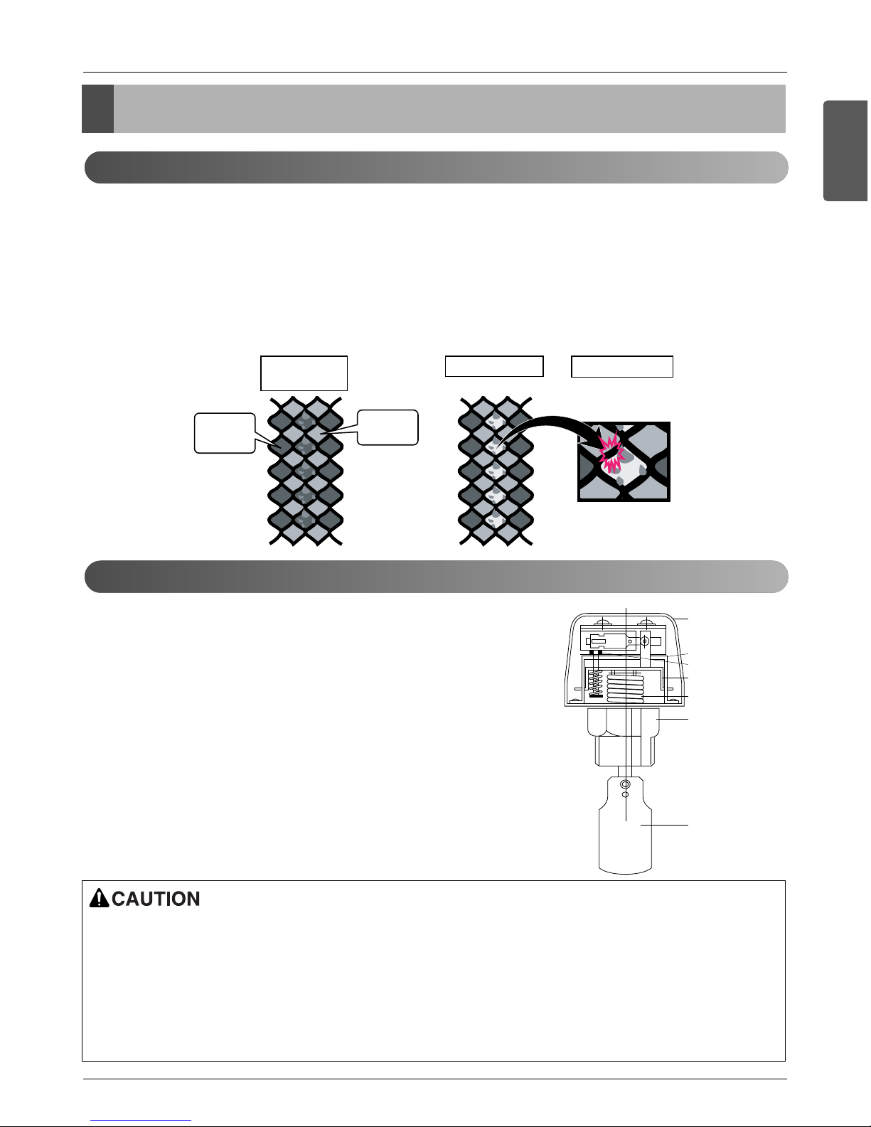
Flow switch work
• It is recommended to install the flow switch to the water collection pipe system
connecting to the outside unit.
(Flow switch acts as the 1st protection device when the heat water is not supplied. If a certain level of water does not flow after installing the flow switch, an
error sign of CH24 error will be displayed on the product and the product will stop
operating.)
• When setting the flow switch, it is recommended to use the product with default
set value to satisfy the minimum flow rate of this product. (The minimum flow rate
range of this product is 50%. Reference flow rate : 8HP - 80LPM, 16HP 155LPM)
• Select the flow switch with the permitted pressure specification considering the
pressure specification of the heat water supply system. (But, the flow switch
must be for AC250V.)
Heat Source
(Water)
Refrigerant
1. Pollution of
Heat source
2. Partially frozen 3. Damage
1 inch or
3/4 inch
socket
Cover
Micro-switch
Adjustment screw
Vibration plate
Bellows
Pad
• If the set value does not satisfy the minimum flow rate or if the set value is changed by the user arbitrarily, it can result
in product performance deterioration or serious product problem.
• If the product is operated with the heat water supply not flowing smoothly, it can damage the heat exchanger or cause
serious product problems.
• In case of CH24 or CH180 error, there is a possibility that the plate type heat exchanger is partially frozen inside. In this
case resolve the issue of partial freezing and then operate the product again. (Cause of partial freezing : Insufficient
heat water flow rate, water not supplied, insufficient coolant, alien particle penetrated inside plate type heat exchanger)
Product protection device
26 Outside Unit
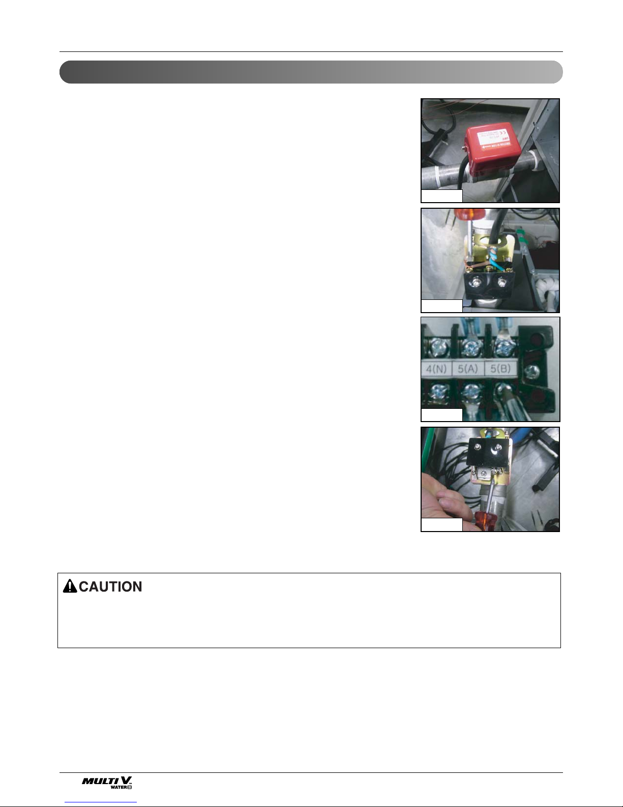
Installation of flow switch
• The flow switch must be installed at the horizontal pipe of the heat water supply outlet of the product and check the direction of the heat water flow before the installation. (Picture 1)
• When connecting the flow switch to the product, remove the jump wire to connect to
the communication terminal (5(A) and 5(B)) of the outside unit control box. (Picture
2, 3) (Open the cover of the flow switch and check the wiring diagram before connecting the wires. The wiring method can differ by the manufacturer of the flow
switch.)
• If necessary, adjust the flow rate detection screw after consulting with an expert and
adjust to the minimum flow rate range. (Picture 4) (Minimum flow rate range of this
product is 50%. Adjust the flow switch to touch the contact point when the flow rate
reaches 50% of the flow rate.)
- Reference flow rate : 8HP - 80LPM, 16HP - 155LPM
• When the product operates while the flow switch touches the contact point at the flow rate range out of the permitted
range, it can cause product performance deterioration or serious product problem.
• Must use the normal closed type flow switch - Circuit of outside unit is normal closed type
Picture 1
Picture 2
Picture 3
Picture 4
Refrigerant piping system
Installation Manual 27
ENGLISH
Refrigerant piping system
Y branch method
Ú Refrigerant pipe diameter from
branch to branch (B,C,D)
Ú Total pipe length =
A+B+C+D+a+b+c+d+e ≤ 300m(984ft)
Ú Outside unit
Ⓐ
~ 1st branch Ⓑ:
Main pipe diameter (A)
L Below 150m(492ft)
Below H 50m(164ft)
l
Below 40m(131ft)
Below 15m(49ft)
Indoor unit
direction
1. When installing 1 outside unit
independently
Ex) 5 indoor units connected
Ⓐ : Outside unit
Ⓑ : 1st branch (Y branch)
Ⓒ : Indoor units
Ⓓ : Indoor unit
For the first branch pipe (B), use the branch pipe
that fits the main pipe diameter (A).
Outside unit
Liquid pipe Gas pipe
capacity
[mm(inch)] [mm(inch)]
8 HP Ø9.52(3/8) Ø22.2(7/8)
10 HP Ø9.52(3/8) Ø22.2(7/8)
16 HP Ø12.7(1/2) Ø28.58(1-1/8)
20 HP Ø12.7(1/2) Ø28.58(1-1/8)
Total capacity of indoor units connected
to after branching [kW(Btu/h]
≤ 5.6(19,100) Ø6.35(1/4) Ø12.7(1/2)
<16(54,600) Ø9.52(3/8) Ø15.88(5/8)
≤ 22.4(76,400) Ø9.52(3/8) Ø19.05(3/4)
< 33(112,600) Ø9.52(3/8) Ø22.2(7/8)
< 47(160,400) Ø12.7(1/2) Ø28.58(1-1/8)
< 71(242,300) Ø15.88(5/8) Ø28.58(1-1/8)
< 104(354,900) Ø19.05(3/4) Ø34.9(1-3/8)
104(354,900) ≤ Ø19.05(3/4) Ø41.3(1-5/8)
Liquid pipe
[mm(inch)]
Gas pipe
[mm(inch)]
Longest pipe length (Equivalent pipe length)
A + B + C + D + e ≤ 150m(492ft)( 175m(574ft))
Longest pipe length after 1st branching
B + C + D + e ≤ 40m(131ft)
High/Low difference (Outside unit ÷ Indoor unit)
H ≤ 50m(164ft)
High/Low difference (Indoor unit ÷ Indoor unit)
h ≤ 15m(49ft)
L
ℓ
H
h
• When the pipe diameter (B) connected after 1st branching is larger than the main pipe diameter (A), Install the pipe with the pipe
diameter (B) after 1st branching that is the same as the main pipe diameter (A).
Ex) When connecting with 120% of the indoor unit to 10 HP
1) Outside unit main pipe diameter: Ø22.2(7/8) (Gas pipe) / Ø9.52(3/8)(Liquid pipe)
2) Pipe diameter after 1st branching by 120% indoor unit combination : Ø28.58(1-1/8) (Gas pipe) / Ø12.7(1/2) (Liquid pipe)
Therefore set the pipe diameter (B) after 1st branching to Ø22.2(7/8) (Gas pipe) / Ø9.52(3/8) (Liquid pipe) of main pipe diameter (A).
• When the pipe distance corresponding to the farthest indoor unit from the outside unit is 90m(295ft) or above, you must change the
main pipe diameter according to the outside unit capacity in accordance with the following table. (This applies to both the liquid and
gas pipes.)
Gas Pipe Liquid Pipe
8, 10 HP .........................................................................Ø22.2(7/8) ’ Ø25.4(1) 8, 10 HP .........................................................................Ø9.52(3/8) ’ Ø12.7(1/2)
16, 20 HP .......................................................................Ø28.58(1-1/8) ’ Ø31.8(1-1/4) 16, 20 HP.......................................................................Ø12.7(1/2) ’ Ø15.88(5/8)
28 Outside Unit
Below 2m(6.6ft)
Master
Slave
Indoor unit
direction
Below 10m
L Below 150m(492ft)
Below H 50m(164ft)
l
Below 40m(131ft)
Below 15m(49ft)
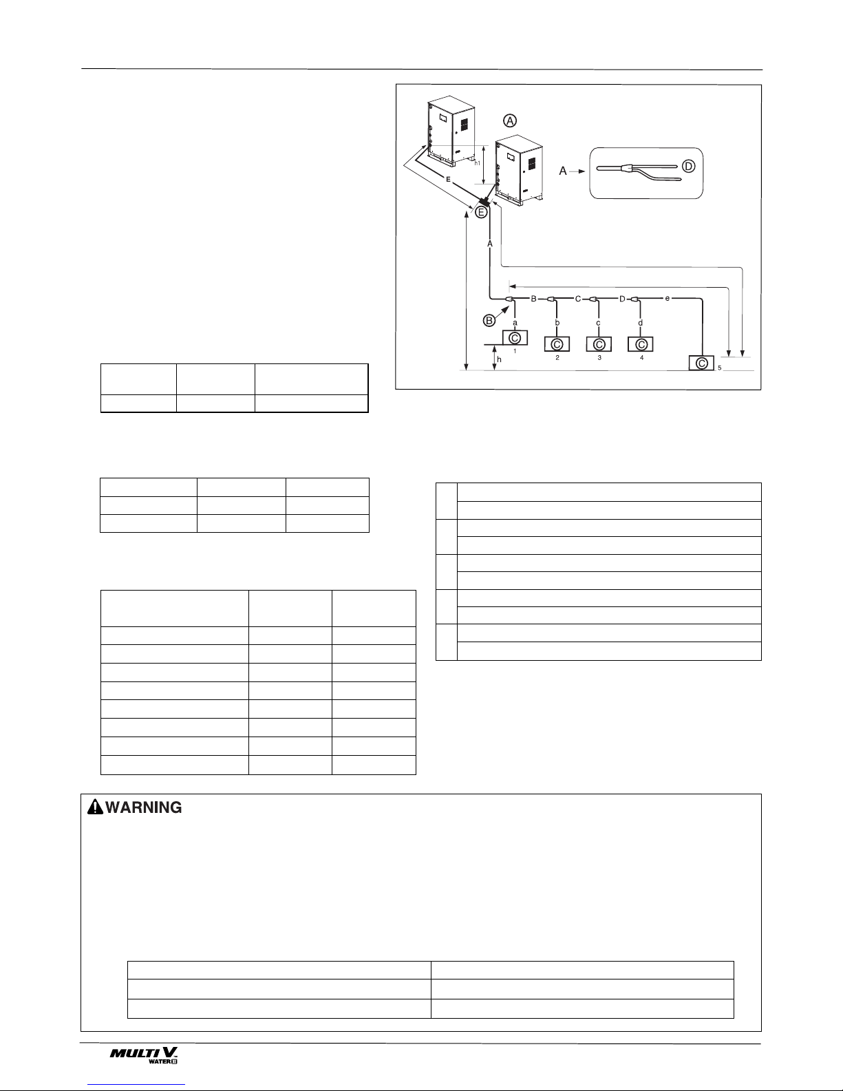
Ú
Slave outside unit ~ Connecting
branch pipe
Ⓔ
: Pipe diameter
between outside units
(E)
Ú
Connecting branch pipe
Ⓔ
~ 1st
branch part
Ⓑ
: Main pipe diameter (A)
Ú
Refrigerant pipe diameter from branch
to branch (B, C, D)
Ú
Total refrigerant pipe length =
A + B + C + D + a + b + c + d + e ≤ 300m(984ft)
2. When installing 2 outside units
Ex) 5 indoor units connected
Ⓐ : Outside units
Ⓑ : 1st branch
Ⓒ : Indoor units
Ⓓ : Indoor unit direction
Ⓔ : Connecting branch pipe between out-
side units
h Connecting branch pipe between outside
units: ARRCN20(ⓔ)
For the first branch pipe (B), use the branch pipe
that fits the main pipe diameter (A).
Refrigerant piping system
Liquid pipe Gas pipe
Low/high pressure
[mm(inch)] [mm(inch)]
common pipe
Ø9.52(3/8)/12.7(1/2)
Ø22.2(7/8)/28.58(1-1/8)
Ø19.05(3/4)
Outside unit capacity Liquid pipe[mm(inch)] Gas pipe [mm(inch)]
24,30HP Ø19.05(3/4) Ø34.9(1-3/8)
32,40HP Ø19.05(3/4) Ø41.3(1-5/8)
Longest pipe length (Equivalent pipe length)
A + B + C + D + e ≤ 150m(492ft)( 175m(574ft))
Longest pipe length after 1st branching
B + C + D + e ≤ 40m(131ft)
High/Low difference (Outside unit ÷ Indoor unit)
H ≤ 50m(164ft)
High/Low difference (Indoor unit ÷ Indoor unit)
h ≤15m(49ft)
High/Low difference (Outside unit ÷ Outside unit)
h ≤ 2m(6.6ft)
L
ℓ
H
h
h1
Total capacity of indoor units connected
to after branching [kW(Btu/h]
≤ 5.6(19,100) Ø6.35(1/4) Ø12.7(1/2)
<16(54,600) Ø9.52(3/8) Ø15.88(5/8)
≤ 22.4(76,400) Ø9.52(3/8) Ø19.05(3/4)
< 33(112,600) Ø9.52(3/8) Ø22.2(7/8)
< 47(160,400) Ø12.7(1/2) Ø28.58(1-1/8)
< 71(242,300) Ø15.88(5/8) Ø28.58(1-1/8)
< 104(354,900) Ø19.05(3/4) Ø34.9(1-3/8)
104(354,900) ≤ Ø19.05(3/4) Ø41.3(1-5/8)
Liquid pipe
[mm(inch)]
Gas pipe
[mm(inch)]
• When
the pipe diameter (B) connected after 1st branching is larger than the main pipe diameter (A), Install the pipe with the pipe diameter (B)
after 1st branching that is the same as the main pipe diameter (A).
Ex) When connecting with 120% of the indoor unit to 10 HP.
1) Outside unit main pipe diameter: Ø22.2(7/8) (Gas pipe) / Ø9.52(3/8)(Liquid pipe)
2) Pipe diameter after 1st branching by 120% indoor unit combination : Ø28.58(1-1/8) (Gas pipe) / Ø12.7(1/2) (Liquid pipe)
Therefore set the pipe diameter (B) after 1st branching to Ø22.2(7/8) (Gas pipe) / Ø9.52(3/8)(Liquid pipe) of main pipe diameter (A).
• When the pipe distance corresponding to the farthest indoor unit from the outside unit is 90m or above, you must change the main pipe diameter according to the outside unit capacity in accordance with the following table. (This applies to both the liquid and gas pipes.)
Gas Pipe Liquid Pipe
24,30HP..................................................................Ø37.9 ’ Ø38.1(1-1/2) 24,30,32,40HP
...................................................Ø
19.05(
3/4) ’ Ø22.2(7/8)
32,40HP............................................................Ø41.3(1-5/8)
Installation Manual 29
ENGLISH
Refrigerant piping system
10m or
less
L150m(492ft)
l
40m(131ft)
Slave2
Slave1
Master
Below 2m(6.6ft)
(h1)
Indoor unit
direction
H 50m(164ft)
15m(49ft)
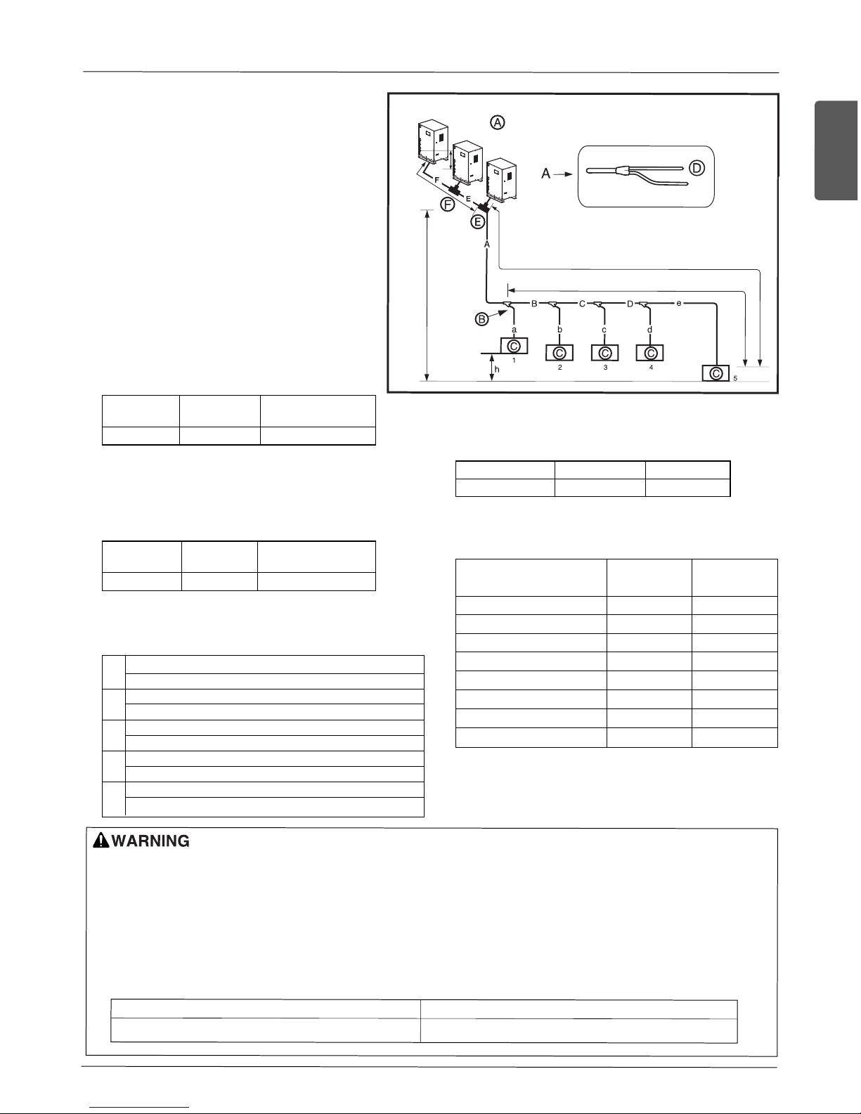
3. When installing 3 outside units
Ex) 5 Indoor Units connected
Ⓐ : Outside Units
Ⓑ : 1st branch (Y branch)
Ⓒ : Indoor Units
Ⓓ : Downward Indoor Unit
Ⓔ : Connection branch pipe between
Outside units:ARCNN30
Ⓕ : Connection branch pipe between
Outside units:ARCNN20
Ú
Slave1 outside unit ~ Connecting
branch pipe
Ⓔ
: Pipe diameter
between outside units (E)
Ú
Connecting branch pipe
Ⓔ
~ 1st branch
part
Ⓑ
: Main pipe diameter (A)
Ú
Refrigerant pipe diameter from branch
to branch (B, C, D)
Ú
Total refrigerant pipe length =
A + B + C + D + a + b + c + d + e ≤ 300 m
For the first branch pipe (B), use the branch
pipe that fits the main pipe diameter (A).
Ú
Slave2 outside unit ~ Connecting
branch pipe
Ⓕ
: Pipe diameter
between outside units (F)
• When
the pipe diameter (B) connected after 1st branching is larger than the main pipe diameter (A), Install the pipe with the pipe diameter (B)
after 1st branching that is the same as the main pipe diameter (A).
Ex) When connecting with 120% of the indoor unit to 10 HP.
1) Outside unit main pipe diameter: Ø22.2(7/8) (Gas pipe) / Ø9.52(3/8)(Liquid pipe)
2) Pipe diameter after 1st branching by 120% indoor unit combination : Ø28.58(1-1/8) (Gas pipe) / Ø12.7(1/2) (Liquid pipe)
Therefore set the pipe diameter (B) after 1st branching to Ø22.2(7/8) (Gas pipe) / Ø9.52(3/8)(Liquid pipe) of main pipe diameter (A).
• When the pipe distance corresponding to the farthest indoor unit from the outside unit is 90m or above, you must change the main pipe diameter according to the outside unit capacity in accordance with the following table. (This applies to both the liquid and gas pipes.)
Gas Pipe Liquid Pipe
40,48,50,60HP ............................................Ø41.3(1-5/8) 40,48,50,60HP ............................................Ø19.05(3/4) ’ Ø22.2(7/8)
Liquid pipe Gas pipe
Low/high pressure
[mm(inch)] [mm(inch)]
common pipe
Ø9.52(3/8)/12.7(1/2)
Ø22.2(7/8)/28.58(1-1/8)
Ø19.05(3/4)
Liquid pipe Gas pipe Low/high pressure
[mm(inch)] [mm(inch)] common pipe
Ø15.88(5/8)/19.05(3/4)
Ø34.9(1-3/8)/41.3(1-5/8)
Ø19.05(3/4)
Longest pipe length (Equivalent pipe length)
A + B + C + D + e ≤ 150m(492ft)( 175m(574ft))
Longest pipe length after 1st branching
B + C + D + e ≤ 40m(131ft)
High/Low difference (Outside unit ÷ Indoor unit)
H ≤ 50m(164ft)
High/Low difference (Indoor unit ÷ Indoor unit)
h ≤ 15m(49ft)
High/Low difference (Outside unit ÷ Outside unit)
h ≤ 2m(6.6ft)
L
ℓ
H
h
h1
Outside unit capacity
Liquid pipe[mm(inch)] Gas pipe [mm(inch)]
40,48,50,60HP Ø19.05(3/4) Ø41.3(1-5/8)
Total capacity of indoor units connected
to after branching [kW(Btu/h]
≤ 5.6(19,100) Ø6.35(1/4) Ø12.7(1/2)
<16(54,600) Ø9.52(3/8) Ø15.88(5/8)
≤ 22.4(76,400) Ø9.52(3/8) Ø19.05(3/4)
< 33(112,600) Ø9.52(3/8) Ø22.2(7/8)
< 47(160,400) Ø12.7(1/2) Ø28.58(1-1/8)
< 71(242,300) Ø15.88(5/8) Ø28.58(1-1/8)
< 104(354,900) Ø19.05(3/4) Ø34.9(1-3/8)
104(354,900) ≤ Ø19.05(3/4) Ø41.3(1-5/8)
Liquid pipe
[mm(inch)]
Gas pipe
[mm(inch)]
30 Outside Unit
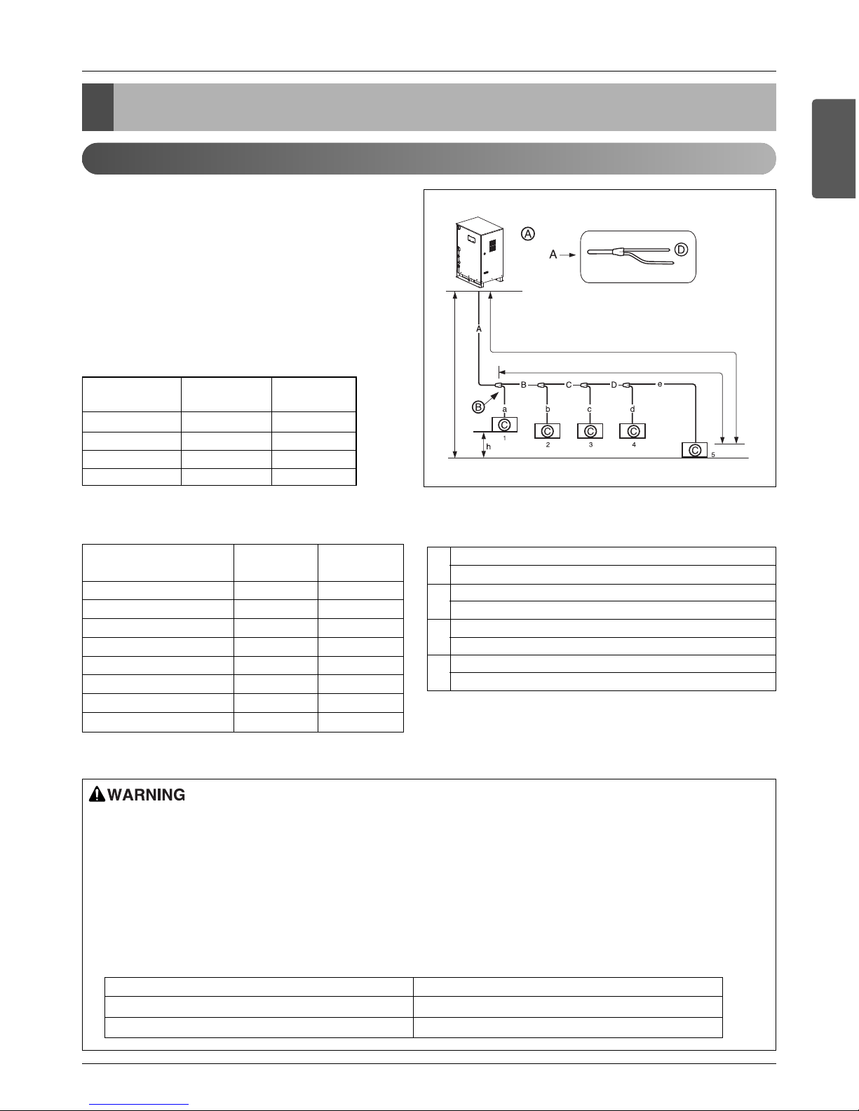
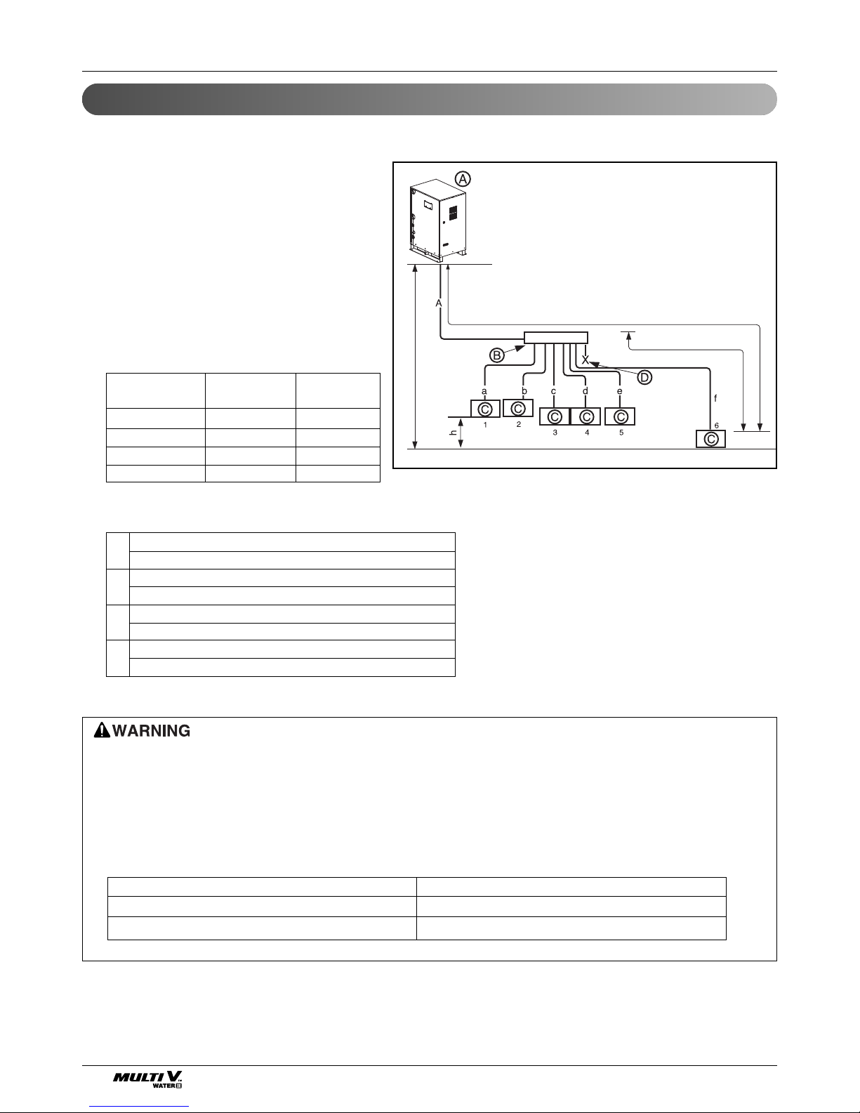
Header branch method
L Below 150m(492ft)
Below H 50m(164ft)
l Below 40m(131ft)
Below 15m(49ft)
Ú
Total refrigerant pipe length = A +a +b +c +d +e +f ≤ 300m(984ft)
1. When installing 1 outside unit independently
Ex) 6 indoor units connected
Ⓐ Outside unit
Ⓑ Header branch
Ⓒ Indoor unit
Ⓓ Seal
• For the pipe length after the header branch (a~f), it is recommended to install the unit so that the difference of the pipe
distance connected to the indoor unit is minimized.
• The large difference in pipe distance can cause performance difference between indoor units.
• After the header branch, you cannot use the Y branch and header branch.
• When the pipe distance corresponding to the farthest indoor unit from the outside unit is 90m(295ft) or above, you must
change the main pipe diameter according to the outside unit capacity in accordance with the following table.
(This applies to both the liquid and gas pipes.)
Ú
Outside unit Ⓐ~ Header branch
part
Ⓑ
: Main pipe diameter (A)
Gas Pipe Liquid Pipe
8, 10 HP .........................................................................Ø22.2(7/8) ’ Ø25.4(1) 8, 10 HP .........................................................................Ø9.52(3/8) ’ Ø12.7(1/2)
16, 20 HP .......................................................................Ø28.58(1-1/8) ’ Ø31.8(1-1/4) 16, 20 HP.......................................................................Ø12.7(1/2) ’ Ø15.88(5/8)
Refrigerant piping system
Outside unit
Liquid pipe Gas pipe
capacity
[mm(inch)] [mm(inch)]
8 HP Ø9.52(3/8) Ø22.2(7/8)
10 HP Ø9.52(3/8) Ø22.2(7/8)
16 HP Ø12.7(1/2) Ø28.58(1-1/8)
20 HP Ø12.7(1/2) Ø28.58(1-1/8)
Longest pipe length (Equivalent pipe length)
A +f ≤ 150m(492ft)( 175m(574ft))
Longest pipe length after 1st branching
f ≤ 40m(131ft)
High/Low difference (Outside unit ÷ Indoor unit)
H ≤ 50m(164ft)
High/Low difference (Indoor unit ÷ Indoor unit)
h ≤ 15m(49ft)
L
ℓ
H
h
 Loading...