

Page 1

INSTALLATION MANUAL
AIR
CONDITIONER
www.lg.com
Hydro Kit (For High Temperature)
For more information, Refer to the CD or LG Web site (www.lg.com).
Original instruction
Please read this installation manual completely before installing the product.
Installation work must be performed in accordance with the national wiring
standards by authorized personnel only.
Please retain this installation manual for future reference after reading it
thoroughly.
[
Representative
] LG Electronics Inc. EU Representative : LG Electronics European Shared
Service Center B.V. Krijgsman 1, 1186 DM Amstelveen, The Netherlands
[Manufacturer] LG Electronics Inc. Changwon 2nd factory 84, Wanam-ro, Seongsan-gu,
Changwon-si, Gyeongsangnam-do, KOREA
P/NO : MFL67798102
ENGLISH
ITALIANO
ESPAÑOL FRANÇAIS
DEUTSCH
ΕΛΛΗΝΙΚΆ
ČEŠTINA
NEDERLANDS
POLSKI
LIMBA ROMÂNĂ
Page 2

Hydro Kit
Installation Manual
TABLE OF CONTENTS
1. SAFETY PRECAUTIONS..............................................................................................................3
2. INSTALLATION PARTS ................................................................................................................8
3. GENERAL INFORMATION ...........................................................................................................9
MODEL INFORMATION ................................................................................................................9
4. INSTALLATION...........................................................................................................................10
TRANSPORTING THE UNIT.......................................................................................................10
SELECTION OF THE BEST LOCATION .....................................................................................11
INSTALLATION SPACE ...............................................................................................................11
FOUNDATION FOR INSTALLATION...........................................................................................12
WATER PIPING AND WATER CIRCUIT CONNECTION ............................................................13
SANITARY WATER TANK AND SANITARY WATER TANK KIT..................................................16
INSTALLATION SCENES............................................................................................................18
REFRIGERANT PIPING..............................................................................................................20
HOW TO CONNECT WIRINGS...................................................................................................22
WIRING CONNECTION ..............................................................................................................22
CONNECTING CABLES .............................................................................................................23
5. ACCESSORIES INSTALLATION ................................................................................................24
LOCATION OF ACCESSORIES AND EXTERNAL PARTS CONNECTION ................................24
MAIN PUMP CONNECTION .......................................................................................................27
WATER TANK TEMPERATURE SENSOR CONNECTION.........................................................27
THERMOSTAT.............................................................................................................................28
REMOTE TEMPERATURE SENSOR .........................................................................................31
3WAY VALVE ...............................................................................................................................32
DRY CONTACT ...........................................................................................................................34
6. SYSTEM SET-UP........................................................................................................................35
DIP SWITCH SETTING ...............................................................................................................35
GROUP CONTROL SETTING.....................................................................................................36
INSTALLER SETTING.................................................................................................................40
7. TEST RUN...................................................................................................................................48
CAUTION BEFORE OPERATION TEST.....................................................................................48
OPERATION TEST OF WATER PIPE .........................................................................................48
TROUBLESHOOTING.................................................................................................................49
2
Hydro Kit
Page 3
Safety Precautions
1. Safety Precautions
To prevent injury to the user or other people and property damage, the following instructions must be followed.
■
Be sure to read before installing the unit.
■
Be sure to observe the cautions specified here as they include important items related to safety.
■
Incorrect operation due to ignoring instruction will cause harm or damage. The seriousness is classified
by the following indications.
■ Meanings of symbols used in this manual are as shown below.
WARNING
CAUTION
This symbol indicates the possibility of death or serious injury.
This symbol indicates the possibility of injury or damage to properties only.
WARNING
Be sure not to do.
Be sure to follow the instruction.
Hydro Kit Installation Manual 3
ENGLISH
■ Installation
Do not use a defective
or underrated circuit
breaker. Use this appliance on a dedicated
circuit.
• There is risk of fire or
electric shock.
For electrical work,
contact the dealer,
seller, a qualified electrician, or an Authorized Service Center.
• There is risk of fire or
electric shock.
Always ground the unit.
• There is risk of fire or
electric shock.
Install the panel and
the cover of control
box securely.
• There is risk of fire or
electric shock.
Always install a dedicated circuit and
breaker.
• Improper wiring or installation may cause fire or
electric shock.
Use the correctly rated
breaker or fuse.
• There is risk of fire or
electric.
Page 4

Safety Precautions
4
Hydro Kit
Be sure the installation
area does not deteriorate with age.
• If the base collapses, the
unit could fall with it,
causing property damage, unit failure, and personal injury.
Do not install the water
pipe system as Open
loop type.
• It may cause failure of
unit.
Do not install the unit
outside.
• It may cause damage to
the unit.
The refrigerant of this
unit is R134a and the
unit is connected to the
outdoor unit where
R410A refrigerant is
used.
• The installation tool such
as manifold gauge
should comply with
R410A.
For installation, always
contact the dealer or an
Authorized Service
Center.
• There is risk of fire, electric shock, explosion, or
injury.
Do not install the unit
on a defective installation stand.
• It may cause injury, accident, or damage to the
unit.
Do not modify or extend the power cable.
• There is risk of fire or
electric shock.
Do not install, remove,
or reinstall the unit by
yourself (customer).
• There is risk of fire, electric shock, explosion, or
injury.
For antifreeze, always
contact the dealer or an
authorized service center.
• Almost the antifreeze is
a toxic product.
Use a vacuum pump or inert (nitrogen) gas when doing leakage test or purging air. Do not compress air or oxygen and do not use flammable gases.
• There is the risk of death, injury, fire or explosion.
Page 5

Hydro Kit Installation Manual 5
Safety Precautions
ENGLISH
Take care to ensure
that power cable could
not be pulled out or
damaged during operation.
• There is risk of fire or
electric shock.
Do not place anything
on the power cable.
• There is risk of fire or
electric shock.
Do not plug or unplug
the power supply plug
during operation.
• There is risk of fire or
electric shock.
Do not touch (operate)
the unit with wet hands.
• There is risk of fire or
electric shock.
Do not place a heater
or other appliances
near the power cable.
• There is risk of fire or
electric shock.
Do not allow water to
run into electric parts.
• There is risk of fire, failure of the unit, or electric
shock.
■ Operation
Do not store or use
flammable gas or combustibles near the unit.
• There is risk of fire or
failure of unit.
Do not use the unit in a
tightly closed space for
a long time.
• It may cause damage to
the unit.
When flammable gas
leaks, turn off the gas
and open a window for
ventilation before turning the unit on.
• There is risk of explosion
or fire.
If strange sounds, or
small or smoke comes
from unit, turn the
breaker off or disconnect the power supply
cable.
• There is risk of electric
shock or fire.
Stop operation and
close the window in
storm or hurricane. If
possible, remove the
unit from the window
before the hurricane arrives.
• There is risk of property
damage, failure of unit,
or electric shock.
Do not open the front
cover of the unit while
operation. (Do not
touch the electrostatic
filter, if the unit is so
equipped.)
• There is risk of physical
injury, electric shock, or
unit failure.
Page 6
Safety Precautions
6
Hydro Kit
If the unit is not used
for long time, we
strongly recommend
not to switch off the
power supply to the
unit.
• There is risk of water
freezing.
Turn the main power off
when cleaning or maintaining the unit.
• There is risk of electric
shock.
Take care to ensure
that nobody could step
on or fall onto the unit.
• This could result in personal injury and unit
damage.
For installation, always
contact the dealer or an
Authorized Service
Center.
• There is risk of fire, electric shock, explosion, or
injury.
When the unit is
soaked (flooded or submerged), contact an
Authorized Service
Center.
• There is risk of fire or
electric shock.
Be cautious that water
could not be poured to
the unit directly.
• There is risk of fire, electric shock, or unit damage.
Ventilate the unit from
time to time when operating it together with a
stove, etc.
• There is risk of fire or
electric shock.
Page 7
Safety Precautions
Hydro Kit Installation Manual 7
ENGLISH
■ Installation
Always check for gas
(refrigerant) leakage
after installation or repair of unit.
• Low refrigerant levels
may cause failure of unit.
Keep level even when
installing the unit.
• To avoid vibration or
water leakage.
Use two or more people
to lift and transport the
unit.
• Avoid personal injury.
■ Operation
Do not use the unit for
special purposes, such
as preserving foods,
works of art, etc.
• There is risk of damage
or loss of property.
Use a soft cloth to
clean. Do not use harsh
detergents, solvents,
etc.
• There is risk of fire, electric shock, or damage to
the plastic parts of the
unit.
Do not step on or put
anything on the unit.
• There is risk of personal
injury and failure of unit.
Use a firm stool or ladder when cleaning or maintaining the unit.
• Be careful and avoid personal injury.
CAUTION
Page 8
Installation Parts
8
Hydro Kit
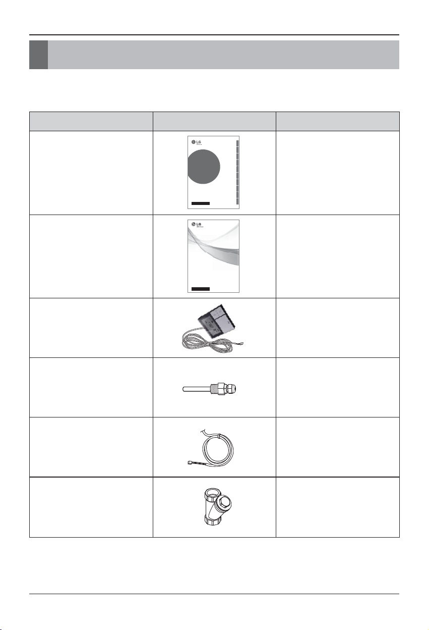
2. Installation Parts
Thank you for choosing LG Electronics Hydro Kit.
Before starting installation, please make it sure that all parts are found inside the unit box.
Item Image Quantity
Installation Manual
1
Owner's Manual 1
Remote Controller
/ Cable
1
Sensor Holder 1
Water Tank
Temperature Sensor
1
Strainer 1
OWNER’S MANUAL
AIR CONDITIONER
Please read this manual carefully before operating
your set and retain it for future reference.
P/NO : MFL67212703
www.lg.com
TYPE :
Hydro Kit (For High Temperature)
ENGLISH
ITALIANO ESPAÑOL FRANÇAIS DEUTSCH
INSTALLATION MANUAL
AIR
CONDITIONER
Please read this installation manual completely before installing the product.
Installation work must be performed in accordance with the national wiring
standards by authorized personnel only.
Please retain this installation manual for future reference after reading it
thoroughly.
Hydro Kit (For High Temperature)
Original instruction
P/NO : MFL67798102
ΕΛΛΗΝΙΚΆ
ČEŠTINA
NEDERLANDS
POLSKI
LIMBA ROMÂNĂ
www.lg.com
Page 9
General Information
Model Information
With advanced inverter technology, Hydro Kit is suitable for applications like under floor heating, and hot water generation. By Interfacing to various accessories user can customize the range
of the application.
Hydro Kit Installation Manual 9
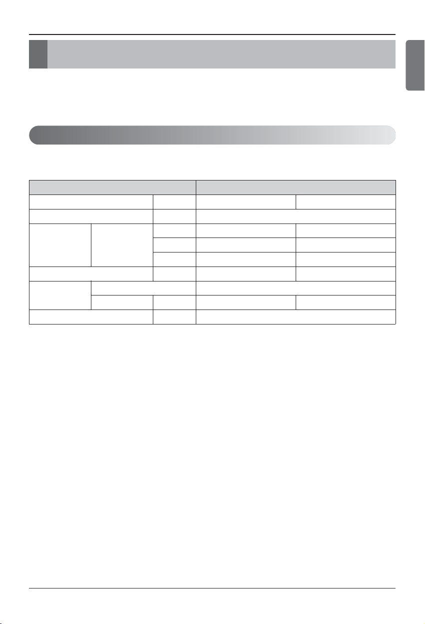
Model name and related information
*1 : Tested under Eurovent Heating condition
(Water temperature 55℃(131℉) 65 ℃(149 ℉) at outdoor ambient temperature
7℃(44℉) / 6℃(42℉))
ENGLISH
Type
Hydro Kit
(For High Temperature)
Model Unit
Power Supply Ø, V, Hz
Capacity Heating
kW
kcal/h
Btu/h
Net Weight kg(lbs)
Refrigerant
Type
Quantity kg(lbs)
Noise Level dB
ARNH08GK3A2 ARNH04GK3A2
1, 220-240, 50
25 13.8
21500 11870
85300 47000
94(207) 88(194)
R134a
3(6.61) 2.3(5.07)
43
3. General Information
Page 10
10
Hydro Kit
Installation
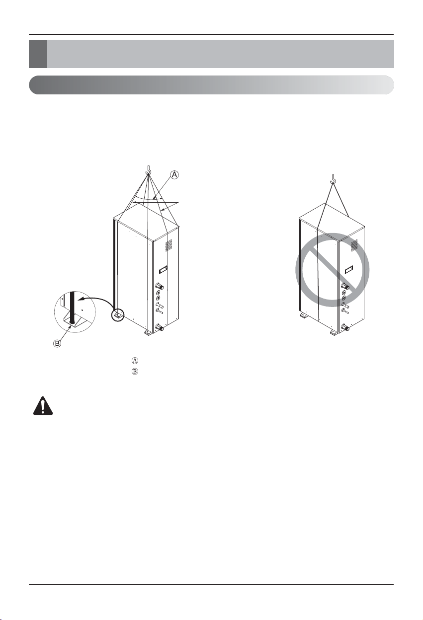
Transporting the Unit
• When carrying the suspended unit, pass the ropes between legs of base panel under the unit.
• Always lift the unit with ropes attached at 6 points so that impact is not applied to the unit.
• Attach the ropes to the unit at an angle Ⓐ of 40° or less.
• Use only accessories and parts which are of the designated specification when installing.
CAUTION
Be very careful while carrying the unit.
- Do not have only one person carry the unit if it is more than 20 kg (44.1 lbs).
- PP bands are used to pack some products. Do not use them as a mean for transportation because
they are dangerous.
- Tear plastic packaging bag and scrap it so that children cannot play with it. Otherwise plastic packaging bag may suffocate children to death.
- When carrying the unit, be sure to support it at 6-points. Carrying and lifting the unit with 4-point
support may make it unstable, resulting in a fall.
4. Installation
Sub line
40º or less
Line supporter
Page 11
Installation
Hydro Kit Installation Manual 11
1. Select space for installing the unit, which will meet the following conditions:
• The place where the unit shall be installed inside.
• The place shall easily bear a load exceeding four times of the unit weight.
• The place where the unit shall be leveled.
• The place shall allow easy water drainage.
• The place where the unit shall be connected to the outdoor unit.
• The place where the unit is not affected by an electrical noise.
• The place where there should not be any heat source or steam near the unit.
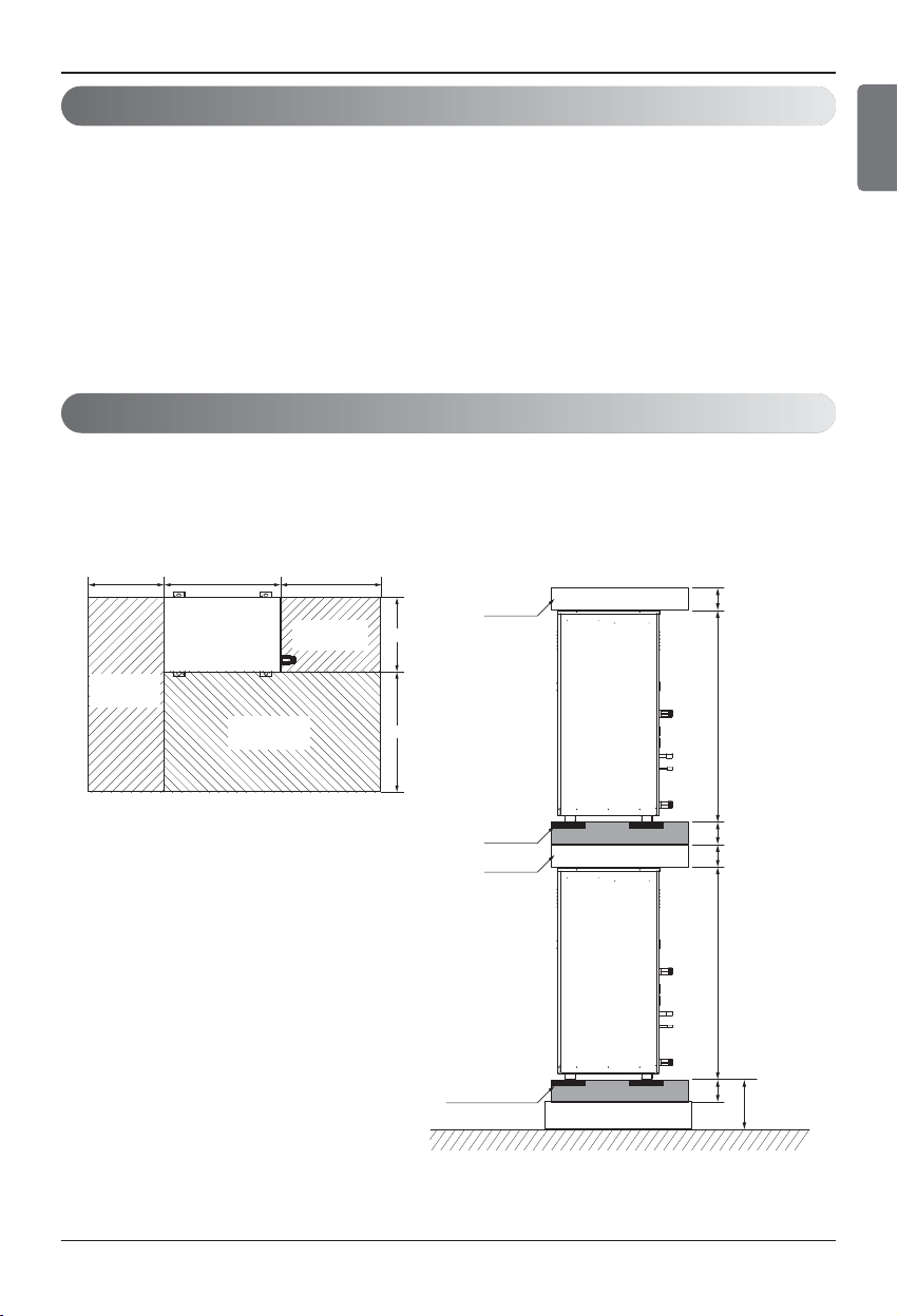
Installation Space
• The following values are the least space for installation.
If any service area is needed for service according to field circumstance, obtain enough service
space.
• The unit of values is mm.
ENGLISH
Selection of the best location
(Unit: mm)
100100100100
10801080
Service space
(left side)
Service space
(front side)
400520300
Piping space
(front side)
space
330
600
(Unit: mm)
Anti Vibration
material
space
H-Beam supporter
Concrete supporter
200
Page 12
Installation
12
Hydro Kit
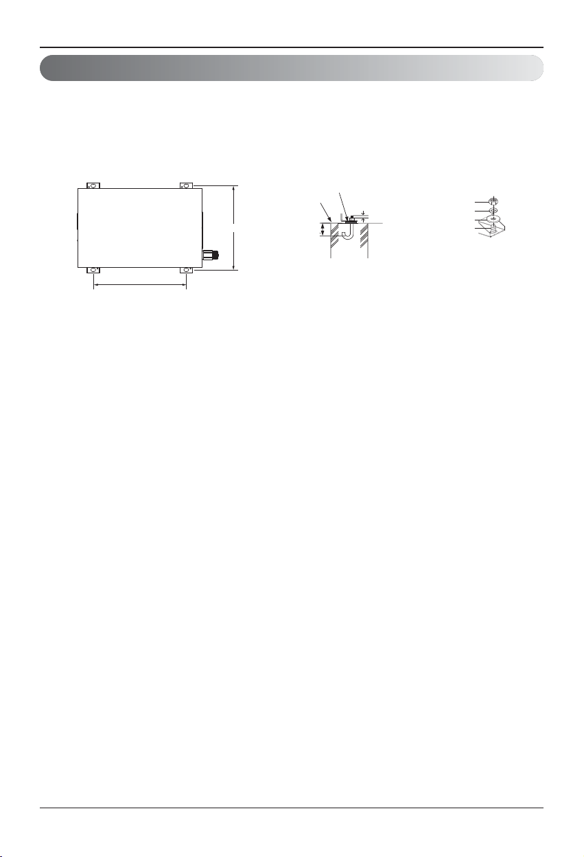
Foundation for Installation
• Fix the unit tightly with bolts as shown below so that the unit will not fall down due to earthquake.
• Noise and vibration may occur from the floor or wall since vibration is transferred through the installation part depending on installation status. Thus, use anti-vibration materials (cushion pad)
fully (The base pad shall be more than 200 mm (7-7/8 inch)).
Anti-vibration material
354
Concrete
base
Support
75
3 or more screw
threads of the
2 bolts must be
shown
Nut
Spring washer
Flat washer
Anchor bolt
392
(Unit: mm)
Page 13

Installation
Hydro Kit Installation Manual 13
General Considerations
Followings should be considered before beginning water circuit connection.
• Service space should be secured.
• Water pipes and connections should be cleaned using water.
• Space for installing external water pump should be provided.
• Never connect electric power while proceeding water charging.
Water Piping and Water Circuit Connection
While installing water pipes, followings should be considered :
•
While inserting or putting water pipes, close the end of the pipe with pipe cap to avoid dust entering.
• When cutting or welding the pipe, always be careful that inner section of the pipe should not be
defective. For example, no weldments or no burrs are found inside the pipe.
• Pipe fittings (e.g. L-shape elbow, T-shape tee, diameter reducer, etc) should be tightened
strongly to be free from water leakage.
• Connected sections should be leakage-proof treatment by applying tefron tape, rubber bushing,
sealant solution, etc.
•
Appropriate tools and tooling methods should be applied to prevent mechanical breakage of the connections.
• Operation time of flow valve(e.g. 3way valve) should be less than 90 seconds.
• Pipe is insulated to prevent heat loss to external environment.
Water Piping and Water Circuit Connection
ENGLISH
Page 14
Installation
14
Hydro Kit
Water cycle
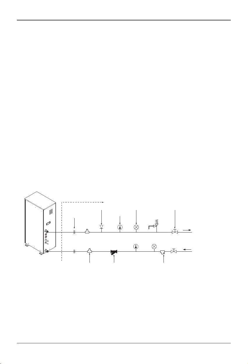
* For the water pipe system, use the closed loop type.
1. For the parts of the water pipe system, use the parts above the design water pressure.
2. For the water pipe, do not use steel pipe.
3. To replace the connected device easily, install the union joint (2).
4.
Install the service port (3) to clean the heat exchanger at each inlet and outlet of the water pipe.
5. Always install a strainer (4) at the inlet of the water pipe.
- For the strainer, use one with 50 mesh or above with measurement diameter of 0.4mm or
less. (Exclude other net)
- Always install the strainer on the horizontal pipe.
(When dirt, trash, rusted pieces get into the water pipe system, it can cause problems to the
product by corroding the metallic material.)
6. Install the air vent (5) at the top of the water pipe.
7. Install a thermometer (6) and pressure gauge (7) at the inlet and outlet of the water pipe.
8. Install the drain valve (8) that can be used for draining the water inside when replacing the part
or providing service.
9. Install the shut-off valve (9) to block the water by closing the valve when replacing the part or
cleaning.
10. Apply insulated treatment on the exterior of the water pipe so that water drops do not form.
11. Install excessive pressure safety valve (10) that meets the design water pressure to prevent
unit or water pipe damage at the pressure increase inside the water pipe system.
12. There is a drain hole at the bottom of the Hydro Kit to prevent risk of electric shock caused by
leakage of water.
Hydro kit
(For High Temperature)
On-site installation (1)
Air vent (5)
Union joint (2) Thermometer (6) Excessive pressure
Pressure gauge(7) Shut-off valve (9)
safety valve(10)
Outlet Water
Inlet water
Drain valve(8)Strainer(4)P/T Service port(3)
[Install water tank]
or
[Install floor heating]
Page 15
Installation
Hydro Kit Installation Manual 15
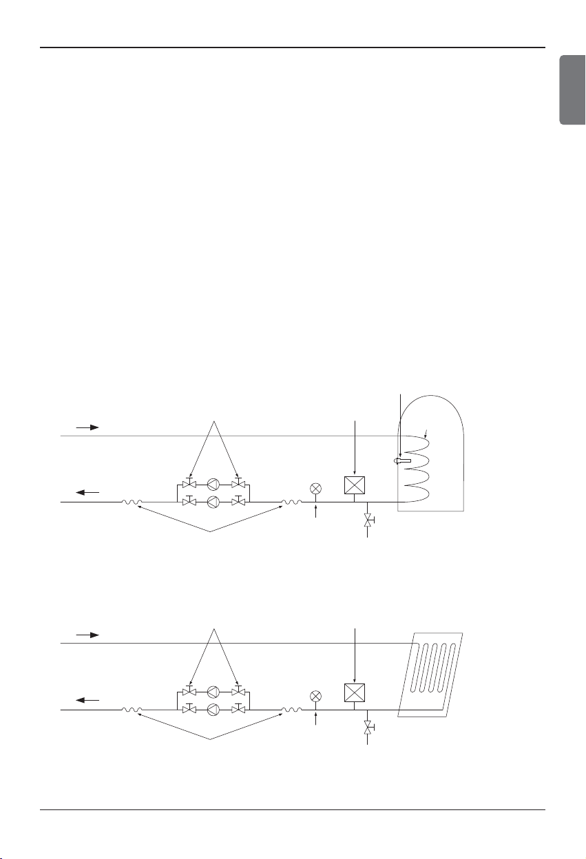
* Water tank & Floor heating installation
1. Use the pump (1) with sufficient capacity to assure loss of overall water pressure and to supply
water to the
Hydro Kit
.
2. Install the shut-off valve (2) on both sides of the pump to clean and repair the pump.
3. Install the flexible joint (3) to prevent noise and vibration transferred from the pump.
4. Install the pressure gauge (4) to monitor the water pressure from water tank. (Option)
5. Install the expansion tank (5) to accommodate the water contracted or expanded from the temperature difference and to supply the water.
6. After the installation of water pipe system is completed, open the water supply valve (6) and supply the water.
7. When installing the water tank, insert the water tank temperature sensor (7) to measure the temperature of the water inside the tank.
- For the water tank temperature sensor, use the sensor supplied on the product.
- When heating the floor, measure the temperature by using the remote controller or remote tem-
perature sensor (Separately sold).
8. Use the water tank (9) with the heat exchange coil (8) installed so that the heat can be exchanged
sufficiently inside the tank.
Installation of water tank
Installation of floor heating
ENGLISH
water tank
temperature sensor (7)
shut-off valve (2)
Expansion tank (5)
Heat
exchange
coil (8)
Pump (1)
Flexible joint (3)
shut-off valve (2)
Pump (1)
Flexible joint (3)
Pressure gauge (4)
Water supply valve (6)
Expansion tank (5)
Pressure gauge (4)
Water supply valve (6)
water tank (9)
(Indirect heating type)
Floor heating coil
(Radiator, FCU can be used)
Page 16
Installation Condition
Installing sanitary water tank requires following considerations :
• Sanitary water tank should be located at the flat place.
• Water quality should comply with EN 98/83 EC Directives.
• As this water tank is sanitary water tank (indirect heat exchange), do not use anti water-freezing
treatment like ethylene grycol.
• It is highly recommend to wash out inside of the sanitary water tank after installation. It ensures
generating clean hot water.
• Near the sanitary water tank, there should be water supply and water drain for easy access and
maintenance.
Sanitary Water Tank and Sanitary Water Tank Kit
Sanitary
Water Tank
Water Tank
Temperature Sensor
Water In
Water Out
Installation
16
Hydro Kit
Strainer
- Use the 50 mesh strainer.
(Exclude scale diameter of 0.4mm or less and other net)
- Check the strainer direction and assemble on the inlet hole (Refer to picture)
- Wrap the Teflon tape on the screw thread of the water pipe for more than 15 times for assembly.
- Install the service port facing downward. (Within left/right 45 degrees)
- Check if there is any leakage on the connecting part.
- Clean the strainer periodically. (Once a year or more frequent)
Water In
Strainer
Front Side
45°
Page 17

Installation
Hydro Kit Installation Manual 17
PT 1/2 inch
Process PT 1/2 inch
female bolt
Inside water tank
Water tank outer wall
Water Tank
Temperature Sensor
Sensor
holder
• If hot water mode is used, make sure to install
sensor to water tank.
• Make PT15A female bolt hole in the water tank,
and install sensor in the water tank.
• Push the sensor into the hole of the sensor holder
cap.
• Lock the sensor holder cap.
Water tank temperature sensor connection
ENGLISH
WARNING :
Installing recirculation pump
When Hydro Kit is used with the sanitary water tank, it is STRONGLY recommended to install
recirculation pump to prevent cold water at the end of hot water supply flooding out and to
stabilize the water temperature inside the sanitary water tank.
- The recirculation pump should be operated when sanitary water demand is not required.
Therefore, external time scheduler to determine when the recirculation pump should turn on
and turn off is required.
- The operating duration time of the recirculation pump is calculated as follow :
Duration time [minute] = k * V / R
k : 1.2 ~ 1.5 is recommended.
(If distance between pump and tank is far, then choose high number.)
V : Volume of sanitary water tank [liter]
R : Water flow rate of pump [liter per minute], which is determined by pump performance
curve.
- The pump operating start time should be prior to the sanitary water demand.
Water Out
Water In
Hot water supply
Sanitary
Water Tank
Shower
(End of Hot
water supply)
Recirculation
Pump
External
Time Scheduler
City water
Page 18

Installation
18
Hydro Kit
Installation Scenes
Some installation scenes are presented for example. As these scenes are conceptual figures, installer should optimize the installation scene according to the installation conditions.
1) Floor Heating only (Without mixing tank)
3) Floor Heating + Hot water
4) Hot water only
Floor heating loopFan coil unit
Radiator
2) Floor Heating only (With mixing tank)
Floor heating loopFan coil unit
Radiator
Floor heating loopFan coil unit
Sanitary
water
tank
Hot water
City water
Radiator
Sanitary
water
tank
Hot water
City water
Pump
3way valve
Bypass valve
Page 19

Installation
Hydro Kit Installation Manual 19
Water Quality
Water quality should comply with EN 98/83 EC Directives. Requirement for resolved chemical ingredients is following table. Detailed water quality condition can be found in EN 98/83 EC Directives.
Frost protection
In areas of the country where entering water temperatures drop below 0℃(32℉), the water pipe must
be protected by using an approved antifreeze solution. Consult your
Hydro Kit
unit supplier for locally approved solutions in your area. Calculate the approximate volume of water in the system. (Except the
Hydro Kit
unit.)
And add antifreeze solution to the total volume to allow for the water
contained in
Hydro Kit
unit.
Parameter Value
Acrylamide 0.10 μg/l
Antimony 5.0 μg/l
Arsenic 10 μg/l
Benzene 1.0 μg/l
Benzo(a)pyrene 0.010 μg/l
Boron 1.0 mg/l
Bromate 10 μg/l
Cadmium 5.0 μg/l
Chromium 50 μg/l
Copper 2.0 mg/l
Cyanide 50 μg/l
1.2-dichloroethane 3.0 μg/l
Epichlorohydrin 0.10 μg/l
Parameter Value
Fluoride 1.5 mg/l
Lead 10 μg/l
Mercury 1.0 μg/l
Nickel 20 μg/l
Nitrate 50 mg/l
Nitrite 0.50 mg/l
Pesticides 0.10 μg/l
Pesticides — Total 0.50 μg/l
Polycyclic aromatic hydrocarbons 0.10 μg/l
Selenium 10 μg/l
Tetrachloroethene and Trichloroethene 10 μg/l
Trihalomethanes — Total 100 μg/l
Vinyl chloride 0.50 μg/l
CAUTION
• If the unit is installed at existing hydraulic water loop, it is important to clean hydraulic pipes to remove
sludge and scale.
• Installing sludge strainer in the water loop is very important to prevent performance degrade.
• Chemical treatment to prevent rust should be performed by installer.
CAUTION
1. Use only one of the above antifreeze.
2. If a antifreeze is used, pressure drop and capability degradation of the system can occur.
3. If one of antifreezes is used, corrosion can occur. So please add corrosion inhibitor.
4. Please check the concentration of the antifreeze periodically to keep same concentration.
5. When the antifreeze is used (for installation or operation), take care to ensure that antifreeze
must not be touched.
6. Ensure to respect all laws and norms of your country about Anti-freeze usage.
7. When hydro kit is applied for heating, the antifreeze never added in the water circuit.
Type of Antifreeze
Minimum Temperature for Freeze Protection
0℃(32℉) -5℃(23℉) -10℃(14℉) -15℃(5℉) -20℃(-4℉) -25℃(-13℉)
Ethylene glycol 0% 12% 20% 30% - -
Propylene glycol 0% 17% 25% 33% - -
Methanol 0% 6% 12% 16% 24% 30%
ENGLISH
Page 20

Installation
20
Hydro Kit
Cut the pipes and the cable
- Use the accessory piping kit or the pipes
purchased locally.
- Measure the distance between the indoor
and the outdoor unit.
- Cut the pipes a little longer than measured
distance.
-
Cut the cable 1.5m longer than the pipe length.
Burrs removal
- Completely remove all burrs from the cut
cross section of pipe/tube.
- Put the end of the copper tube/pipe to downward direction as you remove burrs in order
to avoid to let burrs drop in the tubing.
Pipe welding
- Insert and weld the pipe.
- Always make sure to flow Nitrogen at
0.2kgf/cm
2
within the pipe when welding.
-
If the welding is done without flowing Nitrogen,
it can generate a thick oxidized coating within
the pipe to interfere with normal operation of
valve and compressor etc.
Insulation
- Use rubber foamed insulation material
(EPDM, NBR) with high thermal resistance.
- When installed in humid environment, use
thicker insulation material than usual.
- Insert the insulation material within the product as deep as possible.
❈
The thickness of the above insulation material is
based on thermal conduction rate of 0.036W/m°C.
Nitrogen
Refrigerant Piping
Classification Thickness
Gas pipe(Ø15.88 – 4HP)
(Ø22.2 - 8HP)
t19 above
CAUTION
There is no pump-down function because
Hydro Kit
is the only heating unit. After vacuum drying,
recharge the refrigerant.
Copper
tube
Point down
Copper tube
90°
Direction of Nitrogen
Slanted Uneven Rough
Pipe
Reamer
Regulator
Taping
Valve
Nitrogen
Nitrogen
Inside product
Panel
Insulation
Copper
tube
Page 21

Installation
Hydro Kit Installation Manual 21
Precaution when connecting Heat Recovery systems
Pipe searching process
1. When Pipe searching process is performed,
- Use ‘Mode 1’ if water temperature is higher than 30℃(86℉)
- Use ‘Mode 2’ if water temperature is lower than 30℃(86℉)
2. When Pipe searching process is not performed,
- Check whether ‘CH14’ error occurs in the Hydro Kit.
*Refer to the installation manual of HR unit
(When two
Hydro Kit are
installed)
-
One connection of refrigerant pipe for HR unit is insufficient
for the flow of refrigerant. Join two pipes with a branch pipe
when connecting the
Hydro Kit
(Up to 16kW (54kBut/h) capacity model: ARNH08GK3A2).
- The pipe number of the connected gas pipe and
liquid pipe must be same.
- Flow water in the Hydro Kit when pipe-searching process is performed.
- Pipe-searching process error may occur if the
pipe temperature does not increase.
- It is recommended that Hydro Kit is connected
to No.1 valve and No.2 valve.
Recaution when connecting to synchronous type outdoor unit
ENGLISH
Gas pipe
Liquid pipe
Welding type
No.1, 2 Valve
Ø15.88
Ø9.52
Not control
Control
Hydro kit
Gas pipe
Liquid pipe
DIP S/W setting
Ø22.2
Ø9.52
4
3
2
1
4
3
2
1
Example
Indoor Unit
Indoor Unit
Indoor Unit
Indoor Unit
Indoor Unit
Indoor Unit
Hydro kit
No.2, 3 Valve
Control
No.3, 4 Valve
Control
No.1, 2 Valve
/
No.3, 4 Valve
4
2
4
2
4
2
Control
Indoor Unit
3
Hydro kit
1
Indoor Unit
Hydro kit
3
Indoor Unit
1
Indoor Unit
Hydro kit
3
Hydro kit
1
Page 22

Installation
22
Hydro Kit
Connect the wires to the terminals on the control board individually according to the outdoor unit connection.
*Ensure that the wire color of the outdoor unit and terminal No. are same as those of the indoor unit
respectively.
Communication cable
Power cable
Earth
3(A) 4(B)
Terminal block
of indoor unit
Terminal block
of indoor unit
Terminal block of outdoor unit
Outdoor unit
Indoor unit
DRY2DRY1
WARNING : Make sure that the screws of the terminal are free from
looseness.
Remove the box cover of electric parts and connect the wiring
CAUTION
After checking the above status, prepare for the following wiring :
1)
Use individual power for the unit and refer to the circuit diagram posted on the inside of the control cover.
2) Make sure to install 30A capacity circuit breaker when power is connected to the unit.
3) The bolts used for cable connection may become loose by the vibration generated during the transportation. Make sure to check again and fasten them tightly. (If they are loose, it may cause fire.)
4) Make sure to check power specification.
5) Electrical capacity shall be sufficient.
6) The initial voltage shall be maintained at 90% of the rated voltage on the name plate.
7) The thickness of the power cable complies with the designated specification. (length and thickness of
the power cable)
8) Do not install the circuit breaker in the place where there is a lot of moisture or where it is wet.
9) The following problems may be the cause of voltage drop.
-
Magnetic switch vibration, defective contact, fuse damage, malfunction of overload protection device
❈ Based on the owner’s manual, teach how to operate and use the unit to the user.
(temperature setting, etc.)
Wiring Connection
Communication cable
Power cable
Communication cable
Power cable
CAUTION
When connecting the power and communication
cable, always use the terminal connector (Oring, Y-ring).
Make sure to tighten so that the screw of the terminal does not get loose.
ARNH08GK3A2 ARNH04GK3A2
How to connect wirings
Page 23

Installation
Hydro Kit Installation Manual 23
Connecting Cables
Types of the cables
The distance between communication cable and power cable
- If the power cable and communication cable are tied together, system malfunction may occur with
electrostatic, electromagnetic combination effect causing the interference signal. If communication
cable is connected along with power cable, secure at least 50mm distance between indoor unit
power cable and communication cable.
It is the value with the assumption of the length of the parallel cable as 100 m. If it is longthan 00m,
it shall be calculated again with proportional to the added length.
If the distance is secured as the previous page, and the distortion in the waveform of the power still
occurs, increase the distance.
※ When several power cables are inserted into the transmission line, or tied together, make sure to
consider the following issues.
- Power cables and communication lines shall not be in the same transmission line.
- Power cables and communication lines shall not be tied together.
Classification types Cable cross section
Power cable(CV) mm2 x cores 4.0 x 3
Communication cable(VCTF-SB) mm2 x cores 1.0~1.5 x 2
WARNING
• Are all of the indoor units and outdoor units grounded?
• If grounding is not properly done, there is a risk of electric shock. Grounding must be done by a
qualified technician.
• Consider the surrounding conditions(surrounding temperature, direct sunlight, rain water, etc.)
when wiring the cable.
• The thickness of the power cable is the minimum thickness of metal conductor cable. Use
thicker cable considering the voltage drop.
It is the value with the assumption of the length of the parallel cable as 100 m.
If it is longer than 100m, it shall be calculated again with proportional to the added length.
If the distortion in the waveform of the power still occurs despite securing the distance, increase
the distance.
※ When several power cables are inserted into the transmission line, or tied together, make sure
to consider the following issues.
- Power cables and communication cable shall not be in the same transmission line.
- Power cables and communication cable shall not be tied together.
ENGLISH
Page 24

Accessories Installation
24
Hydro Kit
Location of Accessories and External Parts Connection
• Connect 3way valve, if both floor heating and hot water is used.
• Connect the separately purchased thermostat.
• Dry contact is an accessory supplied by LG and installed by referring to the attached installation
manual.
• 3way valve, thermostat and pump are external parts for installation, which are not supplied by LG.
After checking each part carefully, install external parts respectively.
• Connect the cable of each accessory to the terminal block of the control box in the Hydro Kit.
• Check the label attached on the terminal block to prevent wrong connection.
• Use the pump of 220-240 voltage and maximum operation current of 4A or less.
• Select a suitable relay for pump capacity when connecting the pump to the unit.
WARNING:
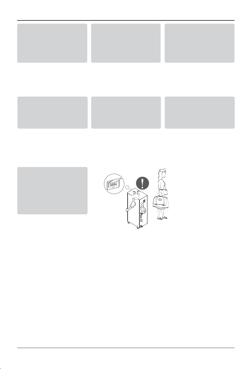
• Install the unit after turning off the main power.
• Do not connect the products out of range specified in the manual.
• Do not work with wet hand.
5. Accessories Installation
Dry contact board attachment location
Dry contact board locking location (CN-CC)
Remote controller locking location (CN-REMO)
Water tank temperature sensor locking location (CN-TH4)
L N L L1 N L N L1 L2
PUMP
(A)
3WAY VALVE
(A)
THERMOSTAT
(Default : 230V AC)
Page 25

Accessories Installation
Hydro Kit Installation Manual 25
2
2
1
3
3
<Wire guide grooves>
Wall
Side
Wall
Side
Wall
Side
Wall
Side
<Connecting order>
<Separating order>
Installation of Wired Remote Controller
1. Please fix tightly using provided screw after
placing remote controller setup board on the
place where you like to setup.
- Please set it up not to bend because poor
setup could take place if setup board bends.
Please set up remote controller board fit to the
reclamation box if there is a reclamation box.
2. Can set up Wired remote controller cable
into three directions.
- Setup direction: the surface of wall reclamation, upper, right
- If setting up remote controller cable into upper
and right side, please set up after removing
remote controller cable guide groove.
❈
Remove guide groove with long nose.
①
Reclamation to the surface of the wall
②
Upper part guide groove
③
Right part guide groove
3. Please fix remote controller upper part into
the setup board attached to the surface of
the wall, as the picture below, and then, connect with setup board by pressing lower
part.
- Please connect not to make a gap at the
remote controller and setup board’s upper and
lower, right and left part.
When separating remote controller from
setup board, as the picture below, after
inserting into the lower separating hole
using screw driver and then, spinning clockwise, remote controller is separated.
- There are two separating holes. Please individually separate one at a time.
- Please be careful not to damage the inside
components when separating.
ENGLISH
Page 26

Accessories Installation
26
Hydro Kit
4. Please connect indoor unit and remote controller using connection cable.
5. Please use extension cable if the distance between wired remote controller and indoor
unit is more than 10m.
Extension cable(10m) model name : PZCWRC1
When installing the wired remote controller, do not bury it in the wall.
(It can cause damage in the temperature sensor.)
Do not install the cable to be 50m or above. (It can cause communication error.)
• When installing the extension cable, check the connecting direction of the connector of the
remote controller side and the product side for correct installation.
•
If you install the extension cable in the opposite direction, the connector will not be connected.
• Specification of extension cable: 2547 1007 22# 2 core 3 shield 5 or above.
CAUTION
Male plug ends
Please check if connector
is normally connected.
Hydro Kit
Female plug ends
Optional extension cable
(purchased separately)
Page 27

Accessories Installation
Hydro Kit Installation Manual 27
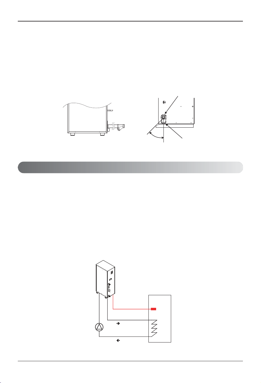
Water tank temperature sensor Connection
• Select the suitable pump by referring to the flow rate table with water temperature difference between the entrance and the exit.
*It is recommended that the flow rate is 36LPM.
• Use the pump with enough capacity to guarantee the loss of entire water
pressure and to supply the Hydro Kit with water.
• Select a suitable relay for pump capacity when connecting the pump to the
unit.
• Connect the relay to the terminal block 11 and 12 of the control box.
• Connect sensor housing to PCB‘CN-TH4’ connector (red).
CAUTION
• Make sure to supply external power with the pump.
CAUTION
• If water tank temperature sensor is not connected, error will occur.
(CH08) Exclude the case of using floor heating.
ENGLISH
Main Pump Connection
Pump
(main)
12
LN
Relay
Pump
CN-TH4
Housing
Water tank
thermistor
Page 28

Accessories Installation
28
Hydro Kit
Installation Condition
Thermostat
Thermostat is generally used to control the unit by air temperature. When thermostat is connected to
the unit, the unit operation is controlled by the thermostat.
Following location should be avoid to secure proper operation :
• Height from floor is approximately 1.5 m.
• Thermostat can not be located where the area may be hidden when door is open.
• Thermostat can not be located where external thermal influence may be applied. (such as
above heating radiator or open window)
CAUTION
1. USE 1~230 V Thermostat.
2. Some electro-mechanical type thermostat has internal delay time to protect compressor. In that case,
mode change can takes time more than user's expectation. Please read thermostat manual carefully
if the unit does not response quickly.
3. Setting temperature range by thermostat can be different with that of the unit. The heating set temperature should be chosen within the setting temperature range of the unit.
4. It is highly recommended that the thermostat should be installed where space heating is mainly applied.
Direct
Sun ray contact area
yes
no
no
1.5 m
no
Page 29

Accessories Installation
Hydro Kit Installation Manual 29
General Information
Hydro Kit
supports following thermostats.
(1) There is no electric circuit inside the thermostat and electric power supply to the thermostat is not
required.
(2) Electric circuit such as display, LED, buzzer, etc is included in the thermostat and electric power
supply is required.
(3) Thermostat generates "Heating ON or Heating OFF" signal according to user"s heating target
temperature.
Type Power Operating Mode Supported
Mechanical (1) 1~ 230 V Heating Only (3) Yes
Electrical (2) 1~ 230 V Heating Only (3) Yes
How to Wire Thermostat
Follow below procedures Step 1 ~ Step 4.
Step 1. Uncover front cover of the unit and open the control box.
Step 2. Identify the power specification of the thermostat.
1~230V thermostat is used in the Hydro Kit (For High Temperature).
Step 3. If it is Heating Only Thermostat, go to step 4.
Step 4. Find terminal block and connect wire as below.
WARNING :
Mechanical type Thermostat.
Do not connect wire (N) as mechanical type thermostat does not require electric power supply.
CAUTION
Do not connect external electric loads.
Wire (L) and (N) should be used only for operation Electric type thermostat.
Never connect external electric loads such as valves, fan coil units, etc.
If connected, Main PCB Assembly 1 can be seriously damaged.
(L) : Live signal from PCB to Thermostat
(N) : Neutral signal from PCB to Thermostat
(H) : Heating signal from Thermostat to PCB
ENGLISH
THERMOSTAT
(Default : 1~ 230 V)
7
8
9
10
L
N
L1
L2
BR
BL
(L) (N) (H)
WH
BK
Thermostat
Page 30

Accessories Installation
30
Hydro Kit
Final Check
• DIP switch setting :
Set DIP switch No. 8 to ‘ON’. Otherwise, the unit can not recognize the thermostat.
• Remote Controller :
- ‘Thermostat’ icon is displayed on the remote controller.
- Button input is prohibited.
Thermostat Operation with Remote Controller
Following features are permitted when thermostat is installed :
• SET TEMP button
• VIEW TEMP button
• Temperature adjusting button(*)
• Sanitary water heating button
(*) : The unit is not turned on/off according to the setting temperature at the remote controller.
It is turned on/off according to the thermostat signal.
Following features are NOT permitted when thermostat is installed :
• Operating mode (heating/ weather-dependent) selection
• Time scheduling
• Operation On / Off
NOTICE
?)<-:?)< -:
78- :
0-)<16/0-) <1 6/
57, -
78-:78- :
57,-57, -
<-58<-58
78-:
57,-
Sequence of thermostat operation
- How to set the heating temperature when thermostat is connected to the Hydro Kit.
Set thermostat
to the heating mode
Adjust the heating temperature,
using the remote controller
Thermostat Icon
Page 31

Accessories Installation
Remote Temperature Sensor
Remote temperature sensor can be installed any place a user wants to detect the temperature.
How to Install Remote Temperature Sensor
Step 1. After deciding where the remote temperature sensor is in-
stalled, decide the location and height of the fixing screws.
(Interval between the screws : 60mm)
Step 2. Insert the connector of the connection wire into the space
for the connector in place of the room temperature sensor.(CN_ROOM)
Step 3. Separately, set the option code of the attached controller
on the indoor unit.
In detail, refer to "installer setting mode".
Step 4. The Connection wire does not matter if you change the color of the wire because of non-
polar.
Fixing screws 60mm
Fixing the
Remote Sensor
2
1
CAUTION
1. Choose the place where the average temperature can be measured for the indoor unit operates.
2. Avoid direct sunlight.
3. Choose the place where the heating devices do not affect the remote sensor.
4. Choose the place where the outlet of the cooling fan do not affect the remote sensor.
5. Choose the place where the remote sensor isn't affected when door is open.
Step 5. Integrate the remote temperature sensor with the screws as the order of arrows.
Hydro Kit Installation Manual 31
ENGLISH
Page 32

Accessories Installation
32
Hydro Kit
WARNING :
• 3way valve should select water tank loop when electric power is
supplied to wire (W) and wire (N).
• 3way valve should select under floor loop when electric power is
supplied to wire (U) and wire (N).
WARNING :
Mice can not be appeared to prevent entering the unit or attacking wires.
3way valve is required to operate sanitary water tank. Role of 3way valve is flow switching between
under floor heating loop and water tank heating loop.
General Information
Hydro Kit
supports following 3way valve.
(1) SPDT = Single Pole Double Throw. Three wires consist of Live (for selecting Flow A), Live 1 (for
selecting Flow B), and Neutral (for common).
(2) Flow A means ‘water flow from the unit to sanitary water tank’
(3) Flow B means ‘water flow from the unit to under floor water circuit’
How to Wire 3Way Valve
Follow below procedures Step 1 ~ Step 2.
Step 1. Uncover front cover of the unit and open the control box.
Step 2. Find terminal block and connect wire as below.
(W) : Live signal (Water tank heating) from PCB to 3way valve
(U) : Live signal (Under floor heating) from PCB to 3way valve
(N) : Neutral signal from PCB to 3way valve
3Way Valve
3way valve
(W) (U) (N)
3WAY VALVE
(A)
BR WH BL
4
L5L1
6
N
Type Power Operating Mode Supported
SPDT
3-wire (1)
1~ 230 V
Selecting “Flow A” between
“Flow A” and “Flow B” (2)
Yes
Selecting “Flow B” between
“Flow A” and “Flow B” (3)
Yes
Page 33

Accessories Installation
Hydro Kit Installation Manual 33
Final Check
• Flow direction :
- Water should flow from water outlet of the unit to sanitary tank water inlet when sanitary tank
heating is selected.
- To verify the flow direction, check temperature at the water outlet of the unit and water inlet of
sanitary water tank.
- If correctly wired, these temperatures should be almost equivalent if thermal insulation of water
pipe is well performed.
• Noise or water pipe vibration while 3way valve operation
- Due to surging effect or cavitation effect, noise or water pipe vibration can be occurred while
3way valve is operating.
- In that case, check followings :
• Is water circuit (both under floor water loop and sanitary water tank loop) fully charged? If not,
additional water charging is required.
• Fast valve operation yields noise and vibration. Appropriated valve operating time is 60~90 seconds.
ENGLISH
Page 34

Accessories Installation
34
Hydro Kit
LG Dry Contact is a solution for automatic control of HVAC system at the owner's best.
In simple words, it's a switch which can be used to turn the unit On/Off after getting the signal from
external sources like key-in lock, door or window switch etc specially used in Hotel rooms.
How to Install Dry Contact
Connect CN_DRY with Control Unit.
- To apply power source through Dry Contact PCB.
Dry Contact
Dry contact
Controller
CN-CC
DRY CONTACT
PCB
DRY CONTACT
PCB
INPUT
220 - 240V
LG does not
supply this section
LG does not
supply this section
4 4
3 3
2 2
1 1
2 2
1 1
RY1
RY2
CN_DRY
NL
Operation Display
Error Check Display
Dry contact
Controller
CN_DRY
4
3
2
4
3
2
1 1
221
1
L
N
220 - 240V
RY1
RY2
CN-CC
DRY CONTACT
PCB
Operation Display
Error Check Display
- To apply power source directly to external source.
(unit : mm)
Page 35

System Set-Up
Hydro Kit Installation Manual 35
As
Hydro Kit
(For High Temperature) is designed to satisfy various installation environment, it is
important to set up system correctly. If not configured correctly, improper operation or degrade of performance can be expected.
DIP Switch Setting
• Turn off electric power supply before setting DIP switch,
There is risk of electric shock.
•
Dip switch is turned on when pulled right.
•
Always set dip switch #6 to ON and #7 to OFF.
•
Do not set dip switch #2 to ON and #3 to OFF.
•
If dip switch is not set as below, the unit may not operate
properly.
x
: OFF●: On
Description
Dip switch setting
Function Default
1 2 3 4 5 6 7 8
Group Control
x ○
●
Installation
Scene
x x
x ● ○
● ●
Emergency
operation
x ○
●
Water pump
control
x
● ○
Thermostat connection
x ○
●
ENGLISH
Master
Slave
Floor heating only
Floor heating + Hot water
Hot water only
High temperature operation
Low temperature operation
Water pump controlled with Hydro Kit
Water pump NOT controlled with Hydro Kit
Thermostat NOT installed
Thermostat installed
6. System Set-Up
Page 36

System Set-Up
36
Hydro Kit
Group Control Setting
Group Control
- Wired remote controller 1 + Many of
Hydro Kit
- Dip Switch in PCB
1. It is possible to connect 16 indoor units(Max) by one wired remote controller.
Set only one indoor unit to Master, set the others to Slave.
2. You can connect all the types of 2nd generation indoor units .
3. It is possible to use wireless remote controller at the same time.
4. It is possible to connect Dry Contact and Central controller at the same time.
- The Master indoor unit is possible to recognize Dry Contact and Central Controller only.
- In case of Central controller and Group controller at the same time, it is possible to connect standard 2series indoor units or later since Sep. 2012.
- In case of Central controller setting, the Central controller can control indoor units after setting
only the address of master indoor unit.
- Slave indoor unit will be operated like master indoor unit.
- Slave indoor unit can not be individually controlled by Central controller.
- Some remote controller can’t perform with Dry Contact and Central controller at the same time.
So contact us further information about it.
¿ Master Setting
- No. 1 Off
¡ Slave Setting
- No. 1 On
Master
Display Error Message
Master
Slave Slave
Only connect serial signal and GND lines
between slave indoor unit
Slave
GND
Signal
12 V
Page 37

System Set-Up
Hydro Kit Installation Manual 37
5. In case that the indoor unit has an abnormal problem an error code will be displayed on the wired
remote controller.
With the exception of the indoor unit with the error, you can control each indoor unit individually.
6. In case of Group Control, it is possible to use following functions.
- Selection of operation options (operation/stop/mode/set temperature)
- It is not possible at some functions.
h Master/Slave setting of indoor units be set possible using a PCB Dip Switch.
h It can be the cause of malfuctions when there is no setting of master and slave.
Accessories for group control setting
- Accessories for group control setting
ENGLISH
CAUTION
• Indoor unit(Hydro Kit)’s group setting is possible which connected same outdoor unit.
• To install Master and Slave indoor unit, the Dip Switch setting should be same.
• Group control is not possible between hydro kit and air conditioner.
• Group control is not possible between mid temperature hydro kit and high temperature hydro kit.
Indoor unit 2 EA +Wired remote controller
❈ PZCWRCG3 cable used for connection
Master
Slave
PZCWRCG3
Master
Page 38

System Set-Up
38
Hydro Kit
Emergency Operation
• Definition of terms
- Trouble : a problem which can stop system operation, and can be resumed temporally under
limited operation without certificated professional's assist.
- Error : problem which can stop system operation, and can be resumed ONLY after certificated
professional's check.
- Emergency mode : temporary heating operation while system met Trouble.
• Objective of introducing 'Trouble'
- Not like airconditioning unit,
Hydro Kit
is generally operated in whole winter season without any
system stopping.
- If system found some problem, which is not critical to system operating for yielding heating
energy, the system can temporarily continue in emergency mode operation with end user's decision.
• Classified Trouble
- Trouble is classified two levels according to the seriousness of the problem : Slight Trouble and
Heavy trouble
- Slight Trouble : Sensor trouble.
- Heavy trouble : Compressor cycle trouble.
- Option Trouble : a problem is found for option operation such as water tank heating. In this
trouble, the troubled option is assumed as if it is not installed at the system.
• Emergency operation level
- When the system is faced with trouble, it stops and waits for user’s decision. : Calling service
center or starting emergency operation.
- To start emergency operation, user simply push ON / OFF button once more.
- Two different levels are prepared for emergency operation : High temperature cycle and low
temperature cycle.
- In emergency operation mode, user can not adjust target temperature.
NOTICE
DIP Switch
(No. 4)
Target
Leaving Water
Temperature
Target
Room Air
Temperature
Target
Sanitary Water
Temperature
High temperature
cycle
OFF 70℃(158℉) 24℃(75℉) 70℃(158℉)
Low temperature
cycle
ON 50℃(122℉) 19℃(66℉) 50℃(122℉)
Page 39

System Set-Up
Hydro Kit Installation Manual 39
• Following features are permitted in emergency operation :
- Operation On/Off
- VIEW TEMP button(*)
- Temperature adjusting button(**)
- Sanitary water heating button
(*) : Temperature measured by failed sensor is displayed as ‘- -’.
(**) : The unit is not turned on/off according to the setting temperature at the remote controller.
It is turned on/off according to the thermostat signal.
• Following features are NOT permitted in emergency operation :
- Operating mode (heating/ weather-dependent) selection
- Time scheduling
- SET TEMP button
• Duplicated trouble : Option trouble with Slight or Heavy trouble
If option trouble is occurred with slight (or heavy) trouble at the same time, the system puts higher
priority to slight (or heavy) trouble and operates as if slight (or heavy) trouble is occurred.
Therefore, sometimes sanitary water heating can be impossible in emergency operation mode.
When sanitary water is not warming up while emergency operation, please check whether the sanitary water sensor and related wiring are connected well or not.
• Emergency operation is not automatically restarted after main electricity power is reset.
In normal condition, the unit operating information is restored and automatically restarted after main
electricity power is reset.
But in emergency operation, automatic re-start is prohibited to protect the unit.
Therefore, user must restart the unit after power reset when emergency operation has been running.
?)<-:?)< -:
78- :
0-)<16/0-) <1 6/
57, -
78-:78- :
57,-57, -
<-58<-58
78-:
57,-
ENGLISH
Page 40

System Set-Up
40
Hydro Kit
Installer Setting
How to enter installer setting mode
CAUTION
Installer setting mode is to set the detail function of the remote controller.
If the installer setting mode is not set correctly, it could cause problems to the unit, user injury or
property damage. This must be set by an certificated installer, and any installation or change that is
carried out by a non-certificated person should be responsible for the results. In this case, free
service cannot be provided.
?)<-:
<-58
78-:
0-)<16/
57,-
Press Function Setting button for 3 seconds
to enter the installer setting mode.
(When you enter the installer setting mode initially, function code is displayed on the bottom of
the LCD screen.)
Repeat pressing button, and the function code
will be changed.
Please refer the code table on the next page.
1
?)<-:
0-)<16/
<-58
78-:
57,-
Function Code Value
Page 41

System Set-Up
Hydro Kit Installation Manual 41
Summary
Function Default Value #1 Value #2 Remark
Disable 3 Min. Delay 02:01 01 -
Remote Air Sensor Connection 03:01
01 : NOT connected.
02 : connected.
-
Celsius/Fahrenheit Switching 04:01
01 : Celsius
02 : Fahrenheit
-
Setting Temp. Selection 05:02
01 : Air Temp.
02 : Leaving water Temp.
-
Auto Dry Contact 06:01
01 : Auto Start OFF
02 : Auto Start ON
-
Address Setting 07:00 00 ~ FF -
Override Setting 08:00
00 : Slave
01 : Master
-
Water Pump Test Run 09:00 01 : Set -
Setting Air Temp.
(Heating Mode)
13:030:016
24℃(75℉) ~ 30℃(86℉)
: Upper Limit of setting range
16℃(60℉) ~ 22℃(71℉)
: Lower Limit of setting range
Setting Leaving Waer Temp.
(Heating Mode)
14:080:046
50℃(122℉) ~ 80℃(176℉)
: Upper Limit of setting range
30℃(86℉) ~ 46℃(114℉)
: Lower Limit of setting range
Setting Sanitary Tank Water Temp.
(Sanitary Water Heating)
15:080:046
50℃(122℉) ~ 80℃(176℉)
: Upper Limit of setting range
30℃(86℉) ~ 46℃(114℉)
: Lower Limit of setting range
Operation mode lock 17:00
00 : Off
01 : On
Setting outdoor Temp. range
(Weather-dependent operation)
23:-10:015
10℃(50℉) ~ 20℃(68℉)
: Upper Limit of setting range
-20℃(-4℉) ~ 05℃(41℉)
: Lower Limit of setting range
Setting indoor air Temp. range
(Weather-dependent operation)
24:021:016
20℃(68℉) ~ 30℃(86℉)
: Upper Limit of setting range
16℃(60℉) ~ 19℃(66℉)
: Lower Limit of setting range
Setting leaving water Temp.
(Weather-dependent operation)
25:080:046
65℃(149℉) ~ 80℃(176℉)
: Upper Limit of setting range
40℃(104℉) ~ 54℃(129℉)
: Lower Limit of setting range
Setting start/maintain time
(Disinfection Operation)
26:000
00 : Disable
01 : Enable
-
26:006:023
01~07 : Starting Date
(01:Sun, 02:Mon, ····, 07:Sat)
00~23 hours
: Starting Time in 24 hours
Setting Temp.
(Disinfection Operation)
27:070:010
40℃(104℉) ~ 70℃(129℉)70
: Maximum heating Temp.
05~60 min
: Maximum heating duration
Setting control parameter
(Sanitary water heating operation)
29:003:000 00~01 :Refer to 46p
Setting sanitary water heating timers
2b:030 5 ~ 95 min (step: 5 min) 2b:180:020 0 ~ 600 min (step: 30 min) 20 ~ 95 min (step: 5 min)
Changing thermal on/off room air Temp.
2E:00 00~03 : Refer to 45p -
Changing thermal on/off leaving water
Temp.
2F:00 00~03 : Refer to 45p -
Program version 30:00 Display Version number -
Changing thermal on/off sanitary tank water Temp.
33:00 00~03 : Refer to 47p -
Select entering/leaving water Temp mode
in Heating Mode
34:00
00 : Based on leaving water Temp
01 : Based on entering water Temp
-
Water Pump operation/delay time set
in Heating Mode
37:000:001
000: Operates according to OFF time setting
001 : Pump always on
001 ~ 060 : OFF Time (minutes)
Forced product operation 39:00
00 : Forced product operation in use
01 : Forced product operation not in use
Dry Contact installation set 41:00
00 : Dry Contact equipped decided on
01 : Dry Contact not installed
02 : Dry Contact installed
*Temp. = Temperature
ENGLISH
Example of Fuction Code Display
Function Code Value #1 Value #2
Page 42

System Set-Up
42
Hydro Kit
Common Setting
• Function Code 02 : Disable 3 minute Delay
Only used for an inspection in a factory.
• Function Code 03 : Remote Air Sensor Connection
If remote air sensor is connected to control the unit by room air temperature, the connection information should be notified to the unit.
Note : If remote air sensor is connected but this function code is not set correctly, the unit can not
be controlled by room air temperature.
• Function Code 04 : Celsius/Fahrenheit Switching
Temperature is displayed in Celsius or Fahrenheit.
• Function Code 05 : Setting Temperature Selection
The unit can be operated according to air temperature or leaving water temperature. The selection
for setting temperature as air temperature or leaving water temperature is determined.
Note : Air temperature as setting temperature is ONLY available when Remote Air Sensor
Connection is enabled and Function Code 03 is set as 02.
• Function Code 06 : Auto Dry Contact
This function enables the Dry Contact to operate under Auto Run mode or Manual mode with
remote controller.
If thermostat is used, value should be changed from "2" to "1".
• Function Code 07 : Address Setting
When Central Controller is installed, address assigning is set by this function.
• Function Code 08 : Override Setting
Override master/slave selection function is to prevent the unit’s different mode operation. If the unit
is set as the slave, it blocks a change of opposite operating mode(cooling/heating).
❈ To use override master/slave selection function is only possible when units are connected in
series to the outdoor unit.
• Function Code 09 : Water Pump Test Run
After water pipe work is done, Water Pump Test Run mode should be
performed to check whether water circulation is normal.
Page 43

System Set-Up
Hydro Kit Installation Manual 43
Temperature Range Setting
• Function Code 13 : Setting Air Temperature in Heating Mode
Determine heating setting temperature range when air temperature is selected as setting temperature.
CAUTION
Only available when remote air temperature sensor is connected.
• Accessory PQRSTA0 should be installed.
• Also, Function Code 03 should be set properly.
• Function Code 14 : Setting Leaving Water Temperature in Heating Mode
Determine heating setting temperature range when leaving water temperature is selected as setting temperature.
• Function Code 15 : Setting Sanitary Tank Leaving Water Temperature
Determine heating setting temperature range of water tank leaving water.
Only available when sanitary water tank temperature sensor is installed.
• Sanitary water tank and sanitary water tank kit should be installed.
• DIP switch No. 2 and 3 should be set properly.
• Function Code 17 : Setting Operation mode lock.
Set the Operation mode lock when Multi V Indoor unit is used only cooling mode in summer and
Hydro Kit is used only heating in winter.
CH51 error occur when Combination Ratio exceed limitation without setting operation
mode lock.
Multi V indoor unit can’t be operated heating mode and Hydro Kit can’t be operated cooling mode when operation mode lock is set.
It can’t be operated with Multi V Indoor unit and Hydro Kit simultaneously when operation
mode lock is set.
NOTICE
NOTICE
ENGLISH
Page 44

System Set-Up
44
Hydro Kit
Temperature Control Parameter Setting and Etc
• Function Code 23, 24, and 25 : Setting Weather-dependent operation
Weather-dependent operation is that the unit automatically adjusts target temperature (leaving
water or room air) according to the outdoor air temperature.
- Value #1 and Value #2 of Function Code 23 : range of outdoor air temperature
- Value #1 and Value #2 of Function Code 24 : range of auto-adjustable target room air temperature
- Value #1 and Value #2 of Function Code 25 : range of auto-adjustable target leaving water temperature
Note : Weather-dependent operation is applied for heating mode only.
Auto-Adjustable
Target Temperature
Value #1 of
Function Code
24 or 25
Value #2 of
Function Code
24 or 25
Temperature profile
of Weather-dependent
operation
Value #2 of
Function Code 23
Value #1 of
Function Code 23
Outdoor
air temperature
Page 45

System Set-Up
Hydro Kit Installation Manual 45
• Function Code 26 and 27 : Setting Disinfection operation
Disinfection operation is special sanitary tank operation mode to kill and to prevent growth of
viruses inside the tank.
- Value #1 of Function Code 26 : Selecting disinfection operation mode. ‘00’ for setting disinfection
mode off, and ‘01’ for setting disinfection mode on.
- Value #2 of Function Code 26 : Determining the date when the disinfection mode is running. ’01’
for Sunday, ’02’ for Monday, … , and ’06’ for Saturday.
- Value #3 of Function Code 26 : Determining the time when the disinfection mode is running. ’00’
for 0:00am, ’01’ for 01:00am, … , ’22’ for 10:00pm, and ’23’ for 11:00pm.
- Value #1 of Function Code 27 : Target temperature of disinfection mode.
- Value #2 of Function Code 27 : Duration of disinfection mode.
WARNING
Vales of Function Code 26
• If Value #1 of Function Code 26 is set as ’00’, Value #2 and Value #3 is not used.
• When Value #1 is set as ’01’, Value #2 is displayed at the position of Value #1 and Value #3 is
displayed at the position of Value #2 due to limited width of the control panel display.
CAUTION
Sanitary water heating should be enabled
• If sanitary water heating is disabled, the disinfection mode
will not be operated although Value #1 of Code 26 is set
as ’01’.
• To use disinfection mode, sanitary water heating should
be enabled.
Time
Value #2 of
Function Code 26
Value #1 of
Function Code
27
Value #2 of
Function Code 27
Water temperature
(Inside sanitary water tank)
Temperature profile
of Disinfection operation
Press repeatedly Button to enable sanitary
tank heating
<Sanitary Water Heating Disable>
<Sanitary Water Heating enable>
ENGLISH
Page 46

• Function Code 2B : Setting sanitary water heating timers
Determine time duration : Operation time and stop time of sanitary tank heating.
- Value #1 of Function Code 2B : This time duration defines how long sanitary tank heating
can be continued.
- Value #2 of Function Code 2B : This time duration defines how long sanitary tank heating
can be stopped. It is also regarded as time gap between
sanitary tank heating cycle.
- Example of timing chart :
System Set-Up
46
Hydro Kit
• Function Code 28 and 29 : Setting control parameter for Sanity water heating operation
Descriptions for each parameters are as following.
- Value #1 of Function Code 28 : temperature gap from Value #2 of Function Code 28.
- Value #2 of Function Code 28 : maximum temperature.
- Example : If Value #1 is set as ‘5’ and Value #2 is set as ’80’, then water tank heating will be
started when the water tank temperature is below 75°C(167°F).
- Value #1 of Function Code 29 : temperature gap from target sanitary water temperature.
- Value #2 of Function Code 29 : Determining heating demand priority between sanitary water
tank heating and under floor heating.
- Example : If user’s target temperature is set as ’50’ and Value #1 is set as ‘3’, then water
tank heating will be turned off when the water temperature is above 53°C(127°F).
Water tank heating will be turned on when the water temperature is below
50°C(122°F).
- Example : If Value #2 is set as ‘0’, that means heating priority is on sanitary water heating, In
this case the under floor can not be heated while sanitary water heating. On the
other hand, if the Value #2 is set as ‘1’, that means heating priority is on under
floor heating, sanitary tank can not be heated while under floor heating.
Sanitary water heating does not operate when it is disabled.
Enabling / Disabling sanitary water heating to operate is determined by pushing button.
When icon is displayed on the remote controller, sanitary water heating is enabled.
(by button input or scheduler programming)
NOTICE
Sanitary tank
heating is enabled
Sanitary tank
heating is required
2B.01 2B.012B.02 2B.022B.02
Time
Sanitary tank
heating operation
Page 47

System Set-Up
Hydro Kit Installation Manual 47
• Function Code 2E and 2F : Changing thermal on/off temperature
Select Thermal on/off Temperature gap.
• Function Code 30 : Remote Controller Program Version
Display Remote Controller Program Version.
• Function Code 33 : Changing thermal on/off temperature in Hot water Mode Select Thermal
on/off Temperature gap.
• Function Code 34 : Setting control parameter for Water flow temperature.
Select entering/leaving water Temp in Heating Mode.
• Function Code 37 : Water pump operation/delay time set in heating mode.
• Function Code 39 : Setting of Forced product operation.
• Function Code 41 : Setting of Dry Contact installation set.
Th On Th Off
0 -0.5°C 1.5°C
1 4°C 6°C
2 2°C 4°C
3 -1°C 1°C
2E : Room Air temperature
Th On Th Off
0 -2°C 2°C
1 -6°C 4°C
2 -2°C 4°C
3 -1°C 1°C
Function code 33 : Sanitary Tank water temperature
Th On Th Off
0 -2°C 2°C
1 -6°C 4°C
2 -2°C 4°C
3 -1°C 1°C
2F : Entering/Leaving Water temperature
ENGLISH
Page 48

Test Run
48
Hydro Kit
• Check whether water flow is smoothly supplied.
• Check whether the flow switch properly operates.
• Check whether the connection status is good.
• Check whether the power cable and communication cable are completely connected.
• Check whether it is 2.0MΩ or above, when insulation resistance between the terminal block
and ground is measured with DC mega tester (DC 500V).
• Never check insulation resistance for the connector of the control board.
Operation Test of Water Pipe
Category Status Checkpoint
Flow
Switch
Error
CH14
Check whether operation of water pipe is normal.
Check for the block inside water pipe.
(Strainer cleaning, valve locked, valve malfunction, air remaining, etc.)
Check problem with flow switch.
(Flow switch disorder, untold operation, disconnection, etc.)
Caution before Operation Test
7. Test Run
Page 49

Test Run
Hydro Kit Installation Manual 49
• This function displays the disorder types at the self diagnostics and the occurrence of the disorder for the product.
• If two or more types of disorders occur simultaneously, it displays in the order of the error
number.
• If inverter PCB error occurs, No. 12 error is displayed in the remote controller, and inverter
PCB board LED can be used to verify detail error display.
• After error occurs, the error code disappears when the disorder is repaired.
❈ Error code 01, 08, 17, 18 can be operated with emergency operation.
Troubleshooting
Error No.
Error Type Main Reasons
01
Air temperature sensor error
Air temperature sensor disconnection or short circuit
02
Gas side temperature sensor error
Gas side temperature sensor disconnection or
short circuit
03
No communication between wired remote controller & indoor unit
The remote controller does not receive the signal
from indoor unit during specific time
05
Indoor unit & outdoor unit communication error
No signal communication between indoor unit &
outdoor unit
06
Liquid side temperature sensor error
Liquid side temperature sensor disconnection or
short circuit
08
Water tank temperature sensor error
Water tank temperature sensor disconnection or
short circuit
09
Indoor unit EEPROM error
Communication between the micro-processor &
the EEPROM / Error due to EEPROM damage
11
Indoor unit & inverter PCB communication error
No signal communication between indoor unit &
inverter PCB
12
Inverter PCB error Error occurrence in inverter PCB
14
Flow switch error Abnormal working of flow switch
15
Water pipe overheated
Water outlet temperature is above 85℃ (Applied
for Mid Temperature model)
16
Water inlet & outlet temperature sensor error
Water inlet & outlet temperature sensor disconnection or short circuit simultaneously
17
Water inlet temperature sensor error
Water inlet temperature sensor disconnection or
short circuit
18
Water outlet temperature sensor error
Water outlet temperature sensor disconnection or
short circuit
ENGLISH
Page 50

Test Run
50
Hydro Kit
Inverter PCB error display method
Red LED means error number 10 digits, and green LED
means 1 digit, and if red and green blink at the same time,
it means the unit of 100.
Ex) When red and green LED blink once at the same
time, and red LED blinks once, and green LED blinks
once: error number 115
Red LED: 10 digits
Green LED: 1 digit
Error No. Error Type Main Reasons
21 Inverter compressor IPM defect
Inverter compressor drive IPM defect / inverter compressor defect
22 Inverter compressor overcurrent Increase of inverter compressor CT value
23 Inverter compressor DC Link low voltage
After inverter activation relay is ON, DC
voltage recharge defect
25 High/low Inverter input voltage
Inverter input voltage exceeds the unit limit
and lasts for 4 s (173V ~ 289V)
26 Inverter compressor activation failure
Inverter compressor error, causing initial
activation failure
27 Inverter PSC/PFC Fault Error Error by overcurrent at inverter input
28 Inverter DC Link high voltage error
Inverter DC voltage recharge, causing compressor OFF
29 Inverter compressor overcurrent
Inverter compressor activation failure or increase of CT value
32
Excessive rise of inverter compressor discharge temperature
Excessive rise of inverter compressor discharge temperature, causing compressor
OFF
34
Excessive rise of high pressure of inverter
compressor
Excessive rise of high pressure of inverter
compressor, causing compressor OFF
35
Excessive drop of low pressure of inverter
compressor
Excessive drop of low pressure of inverter
compressor, causing compressor OFF
36
Low pressure ratio error of inverter compressor
High pressure/low pressure ratio of inverter
compressor is maintained at below 1.8 for 3
min. or more
40 Inverter compressor CT sensor defect Inverter compressor CT sensor defect
41
Inverter compressor discharge pipe temperature sensor defect
Inverter compressor discharge temperature
sensor disconnection or short circuit
42
Low pressure sensor defect of inverter
compressor
Low pressure sensor disconnection or short
circuit of inverter compressor
43
High pressure sensor defect of inverter
compressor
High pressure sensor disconnection or
short circuit of inverter compressor
44
Inverter inside air temperature sensor defect
Inverter inside air temperature sensor disconnection or short circuit
46
Inverter compressor suction pipe temperature sensor defect
Inverter compressor suction temperature
sensor disconnection or short circuit
53
Communication error(indoor unit → outdoor
unit main PCB)
Outdoor unit does not receive signal from
indoor unit
60 Inverter PCB EEPROM error Inverter PCB EEPROM error
62
Excessive rise of inverter heatsink temperature
Inverter PCB heat generation, causing the
rise of heatsink temperature
65 Inverter heatsink temperature sensor defect
Inverter heatsink temperature sensor disconnection or short circuit
73
Overcurrent (Peak) detected at inverter
input
Error by overcurrent detection at inverter
input
Page 51

 Loading...