

LG ARNH04GK3A4 INSTALLATION MANUAL

Please read this installation manual completely before installing the product.
Installation work must be performed in accordance with the national wiring
standards by authorized personnel only.
Please retain this installation manual for future reference after reading it thoroughly.
[
Representative
] LG Electronics Inc. EU Representative : LG Electronics European Shared
Service Center B.V. Krijgsman 1, 1186 DM Amstelveen, The Netherlands
[Manufacturer] LG Electronics Inc. Changwon 2nd factory 84, Wanam-ro, Seongsan-gu,
Changwon-si, Gyeongsangnam-do, KOREA
INSTALLATION MANUAL
AIR-TO-WATER
HEAT PUMP
Hydro Kit
Original instruction (R410A/R32)
www.lg.com
Copyright © 2018 - 2020 LG Electronics Inc. All Rights Reserved.
MFL67086712
Rev.07_092220
РУССКИЙ ЯЗЫК
ENGLISH
ITALIANO ESPAÑOL FRANÇAIS
DEUTSCH
ΕΛΛΗΝΙΚΆ
ČEŠTINA
NEDERLANDS
POLSKI
LIMBA ROMÂNĂ
Table of contents
TABLE OF CONTENTS
3 SAFETY INSTRUCTIONS
9 INSTALLATION PARTS
10 GENERAL INFORMATION
10 Model Information
12 General Information
13 INSTALLATION
13 Transporting the Unit
14 Selection of the best location
14 Installation Space
17 Foundation for Installation
18 Water Piping and Water Circuit Connection
21 Installation Scenes
28 Refrigerant Piping
31 How to connect wirings
32 Wiring Connection
34 Connecting Cables
37 Independent Power Module
39 ACCESSORIES INSTALLATION
39 Location of Accessories and External Parts Connection
41 Main Pump Connection
41 Water tank temperature sensor Connection
42 Thermostat
46 Remote Temperature Sensor
47 3Way Valve
49 2Way Valve
50 Dry Contact
52 External Controller
53 External pump
54 Wi-fi Modem
55 Smart Grid
56 SYSTEM SET-UP
56 DIP Switch Setting
59 Group Control Setting
63 Installer Setting
76 TEST RUN
76 Caution before Operation Test
76 Operation Test of Water Pipe
77 Troubleshooting
79 Airborne Noise Emission
79 Model Designation
2
Hydro Kit
Safety instructions
ENGLISH
Safety instructions
The following symbols are displayed on indoor and outdoor units.
Read the precautions in this manual
carefully before operating the unit.
This symbol indicates that the Operation
Manual should be read carefully.
The following safety guidelines are intended to prevent unforeseen
risks or damage from unsafe or incorrect operation of the appliance.
The guidelines are separated into ‘WARNING’ and ‘CAUTION’ as
described below.
This symbol is displayed to indicate matters and operations
!
that can cause risk. Read the part with this symbol carefully
and follow the instructions in order to avoid risk.
!
WARNING
This indicates that the failure to follow the instructions can cause
serious injury or death.
This appliance is filled with flammable
refrigerant. (for R32)
This symbol indicates that a service
personnel should be handling this
equipment with reference to the
Installation Manual.
!
CAUTION
This indicates that the failure to follow the instructions can cause
the minor injury or damage to the product.
!
WARNING
Installation
• Compliance with national gas regulations shall be observed.
• Do not use a defective or underrated circuit breaker. Use this appliance
on a dedicated circuit.
- There is risk of fire or electric shock.
• For electrical work, contact the dealer, seller, a qualified electrician, or
an Authorized Service Center.
- There is risk of fire or electric shock.
• Always ground the unit.
- There is risk of fire or electric shock.
Hydro Kit
Installation Manual 3

Safety instructions
• Install the panel and the cover of control box securely.
- There is risk of fire or electric shock.
• Always install a dedicated circuit and breaker.
- Improper wiring or installation may cause fire or electric shock.
• Be cautious when unpacking and installing the product.
- Sharp edges could cause injury. Be especially careful of the case
edges and the fins on the condenser and evaporator.
• Use the correctly rated breaker or fuse.
- There is risk of fire or electric.
• Do not modify or extend the power cable.
- There is risk of fire or electric shock.
• Do not install, remove, or reinstall the unit by yourself (customer).
- There is risk of fire, electric shock, explosion, or injury.
• For antifreeze, always contact the dealer or an authorized service
center.
- Almost the antifreeze is a toxic product.
• For installation, always contact the dealer or an Authorized Service
Center.
- There is risk of fire, electric shock, explosion, or injury.
• Do not install the unit on a defective installation stand.
- It may cause injury, accident, or damage to the unit.
• Do not turn on the breaker or power under condition that front panel,
cabinet, top cover, control box cover are removed or opened.
- Otherwise, it may cause fire, electric shock, explosion or death.
• Be sure the installation area does not deteriorate with age.
- If the base collapses, the unit could fall with it, causing property
damage, unit failure, and personal injury.
• Do not install the unit outdoor.
- It may cause damage to the unit.
• Use a vacuum pump or inert (nitrogen) gas when doing leakage test or
purging air. Do not compress air or oxygen and do not use flammable
gases.
- There is the risk of death, injury, fire or explosion.
• The appliance shall be stored in a well-ventilated area where the room
size corresponds to the room area as specified for operation. (for R32)
• Ducts connected to an appliance shall not contain an ignition source.
(for R32)
4
Hydro Kit

Safety instructions
• The appliance shall be stored in a room without continuously operating
ENGLISH
ignition sources (for example: open flames, an operating gas appliance
or an operating electric heater.)
• Means for disconnection must be incorporated in the fixed wiring in
accordance with the wiring rules.
• This equipment shall be provided with a supply conductor complying
with the national regulation.
• Have all electric work done by a licensed electrician according to
"Electric Facility Engineering Standard" and "Interior Wire Regulations"
and the instructions given in this manual and always use a special
circuit.
- If the power source capacity is inadequate or electric work is
performed improperly, electric shock or fire may result.
• Always install a dedicated circuit and breaker.
- Improper wiring or installation may cause fire or electric shock.
• Keep any required ventilation openings clear of obstruction.
• Mechanical connections shall be accessible for maintenance purposes.
• To prevent the mixing of different types of refrigerants, be sure to check
the type of refrigerant used in the outdoor unit.
• When mechanical connectors are reused indoors, sealing parts shall
be renewed. (for R32)
• When flared joints are reused indoors, the flare part shall be refabricated. (for R32)
Operation
• Do not let the air conditioner run for a long time when the humidity is
very high and a door or a window is left open.
- Moisture may condense and wet or damage furniture.
• Take care to ensure that power cable could not be pulled out or
damaged during operation.
- There is risk of fire or electric shock.
• Do not place anything on the power cable.
- There is risk of fire or electric shock.
• Do not plug or unplug the power supply plug during operation.
- There is risk of fire or electric shock.
• Do not touch (operate) the unit with wet hands.
- There is risk of fire or electric shock.
• Do not place a heater or other appliances near the power cable.
- There is risk of fire or electric shock.
Hydro Kit
Installation Manual 5

Safety instructions
• Do not allow water to run into electric parts.
- There is risk of fire, failure of the unit, or electric shock.
• Do not store or use flammable gas or combustibles near the unit.
- There is risk of fire or failure of unit.
• Do not use the product in a tightly closed space for a long time.
- Oxygen deficiency could occur.
• When flammable gas leaks, turn off the gas and open a window for
ventilation before turning the unit on.
- There is risk of explosion or fire.
• If strange sounds, or smell or smoke comes from unit, turn the breaker
off or disconnect the power supply cable.
- There is risk of electric shock or fire.
• Stop operation and close the window in storm or hurricane. If possible,
remove the unit from the window before the hurricane arrives.
- There is risk of property damage, failure of unit, or electric shock.
• Do not open the front cover of the unit while operation. (Do not touch
the electrostatic filter, if the unit is so equipped.)
- There is risk of physical injury, electric shock, or unit failure.
• When the unit is soaked (flooded or submerged), contact an Authorized
Service Center.
- There is risk of fire or electric shock.
• Be cautious that water could not enter the product.
- There is risk of fire, electric shock, or product damage.
• Ventilate the unit from time to time when operating it together with a
stove, etc.
- There is risk of fire or electric shock.
• Turn the main power off when cleaning or maintaining the unit.
- There is risk of electric shock.
• Take care to ensure that nobody could step on or fall onto the unit.
- This could result in personal injury and unit damage.
• For installation, always contact the dealer or an Authorized Service
Center.
- There is risk of fire, electric shock, explosion, or injury.
• If the unit is not used for long time, we strongly recommend not to
switch off the power supply to the unit.
- There is risk of water freezing.
• Periodic ( more than once/year ) cleaning of the dust or salt particles
stuck on the heat exchanger by using water.
6
Hydro Kit
Safety instructions
• Do not use means to accelerate the defrosting process or to clean,
ENGLISH
other than those recommended by the manufacturer.
• Do not pierce or burn refrigerant cycle part.
• Be aware that refrigerants may not contain an odour.
!
CAUTION
Installation
• Always check for gas (refrigerant) leakage after installation or repair of
unit.
- Low refrigerant levels may cause failure of unit.
• Keep level even when installing the unit.
- To avoid vibration or water leakage.
• Use two or more people to lift and transport the unit.
- Avoid personal injury.
• Any person who is involved with working on or breaking into a
refrigerant circuit should hold a current valid certificate from an industry
accredited assessment authority, which authorises their competence to
handle refrigerants safely in accordance with an industry recognised
assessment specification. (for R32)
• The appliance shall be stored so as to prevent mechanical damage
from occurring.
• If anyone other than a licensed Professional installs, repairs, or alters
LG Electronics Air Conditioning Products, the warranty is voided.
- All costs associated with repair are then the full responsibility of the
owner.
• Do not install the product where it will be exposed to sea wind (salt
spray) directly.
- It may cause corrosion on the product. Corrosion, particularly on the
condenser and evaporator fins, could cause product malfunction or
inefficient operation.
• Refrigerant tubing shall be protected or enclosed to avoid damage.
• Flexible refrigerant connectors (such as connecting lines between the
indoor and outdoor unit) that may be displaced during normal
operations shall be protected against mechanical damage.
• The installation of pipe-work shall be kept to a minimum.
• Pipe-work shall be protected from physical damage.
Hydro Kit
Installation Manual 7

Safety instructions
• A brazed, welded, or mechanical connection shall be made before
opening the valves to permit refrigerant to flow between the
refrigerating system parts.
• Dismantling the unit, treatment of the refrigerant oil and eventual parts
should be done in accordance with local and national standards.
Operation
• Do not lay on the cooled floor for long time when the unit is in cooling
operation.
- This could harm to your health.
• Do not use the unit for special purposes, such as preserving foods,
works of art, etc.
- There is risk of damage or loss of property.
• Use a soft cloth to clean. Do not use harsh detergents, solvents, etc.
- There is risk of fire, electric shock, or damage to the plastic parts of
the unit.
• Do not step on or put anything on the unit.
- There is risk of personal injury and failure of unit.
• Use a firm stool or ladder when cleaning or maintaining the unit.
- Be careful and avoid personal injury.
• Servicing shall only be performed as recommended by the equipment
manufacturer. Maintenance and repair requiring the assistance of other
skilled personnel shall be carried out under the supervision of the
person competent in the use of flammable refrigerants. (for R32)
• Do not unplug the power supply plug of Hydro Kit when stopping Hydro
Kit operation. Always turn Hydro Kit off, using the wired remote
controller.
- A plate heat exchanger burst may happen because of disconnection
of communication between Hydro Kit and the outdoor unit.
8
Hydro Kit
OK
Installation Parts
Installation Parts
ENGLISH
Thank you for choosing LG Electronics
Hydro Kit
.
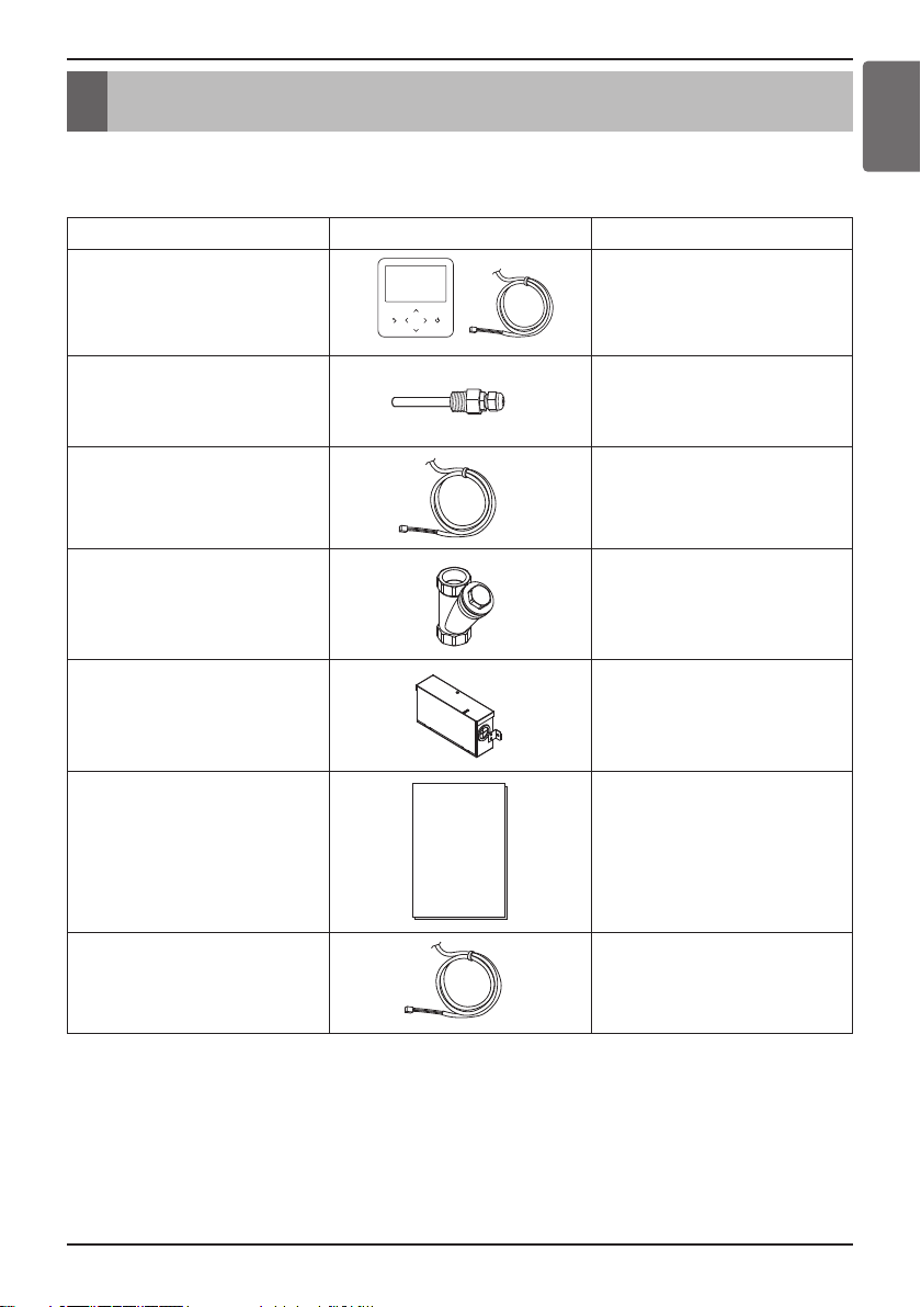
Before starting installation, please make it sure that all parts are found inside the unit box.
Item Image Quantity
Remote Controller
/ Cable
1
Sensor Holder 1
Water Tank Temperature
Sensor
1
Strainer 1
Independent
Power Module
1
(For Medium Temperature)
Owner’s & Installation manual 1
CN_EXT Cable 1
Hydro Kit
Installation Manual 9
General Information
General Information
With advanced inverter technology,
and hot water generation. By Interfacing to various accessories user can customize the range of the
application.
Hydro Kit
is suitable for applications like under floor heating,
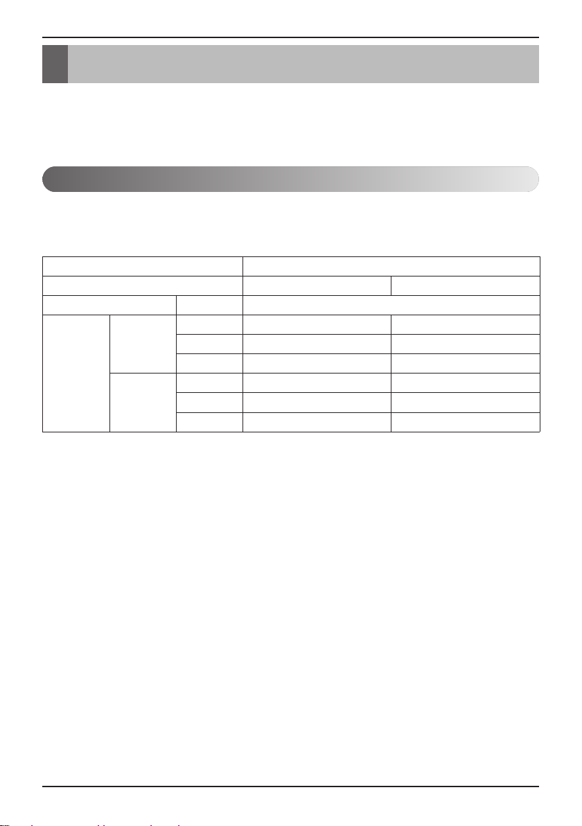
Model Information
Model name and related information
• For Medium Temperature
Type
HP
Power Supply Ø, V, Hz
kW
Cooling
Capacity
Heating
*1 : Tested under Eurovent Heating condition
(water temperature 30 °C → 35 °C at outdoor ambient temperature 7 °C / 6 °C)
*2 : Tested under Eurovent Cooling condition
(water temperature 23 °C → 18 °C at outdoor ambient temperature 35 °C / 24 °C)
- Max Allowable pressure
High side : 4.2 MPa / Low Side : 2.4 MPa
- Max Allowable water temperature
High side : 50 °C / Low side : 10 °C
- Max Allowable water pressure 0.98 MPa (0.3~10 kgf/cm
kcal/h
Btu/h
kW
kcal/h
Btu/h
10 4
28 12.3
24 100 10 580
95 900 42 000
31.5 13.8
27 100 11 870
107 500 47 000
Hydro Kit
1, 220-240, 50
2
)
10
Hydro Kit
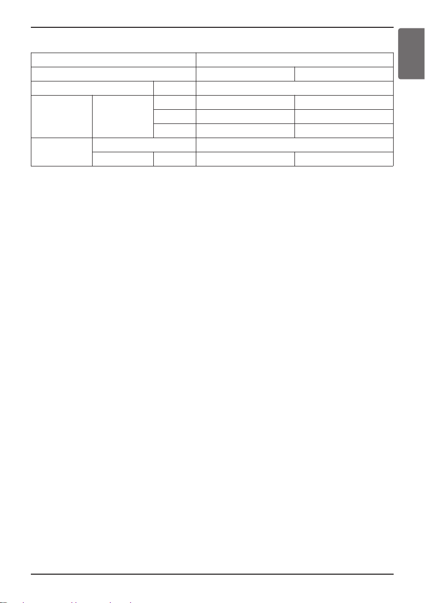
• For High Temperature
General Information
ENGLISH
Type
HP
Power Supply Ø, V, Hz
Capacity Heating
Refrigerant
Quantity kg(lbs)
Type
kW
kcal/h
Btu/h
84
25.2 13.8
21 700 11 870
85 900 47 000
3(6.6) 2.3(5.04)
Hydro Kit
1, 220-240, 50
R134a
*1 : Tested under Eurovent Heating condition
(Water temperature 55 ℃ → 65 ℃ at outdoor ambient temperature 7 ℃ / 6 ℃)
- Max Allowable pressure
High side : 4.2 MPa / Low Side : 2.4 MPa
- Max Allowable water temperature
High side : 80 °C / Low side : 10 °C
- Max Allowable water pressure 0.98 MPa (0.3~10 kgf/cm
2
)
Hydro Kit
Installation Manual 11
General Information
General Information
To extend the functionality of
"accessories".
They are classified by "accessories" and "3rd party accessories" according to the manufacturer.
Accessories are presented LG Electronics, and 3rd party accessories are presented by related
manufacturers.
Hydro Kit
, there are various external auxiliary apparatus called as
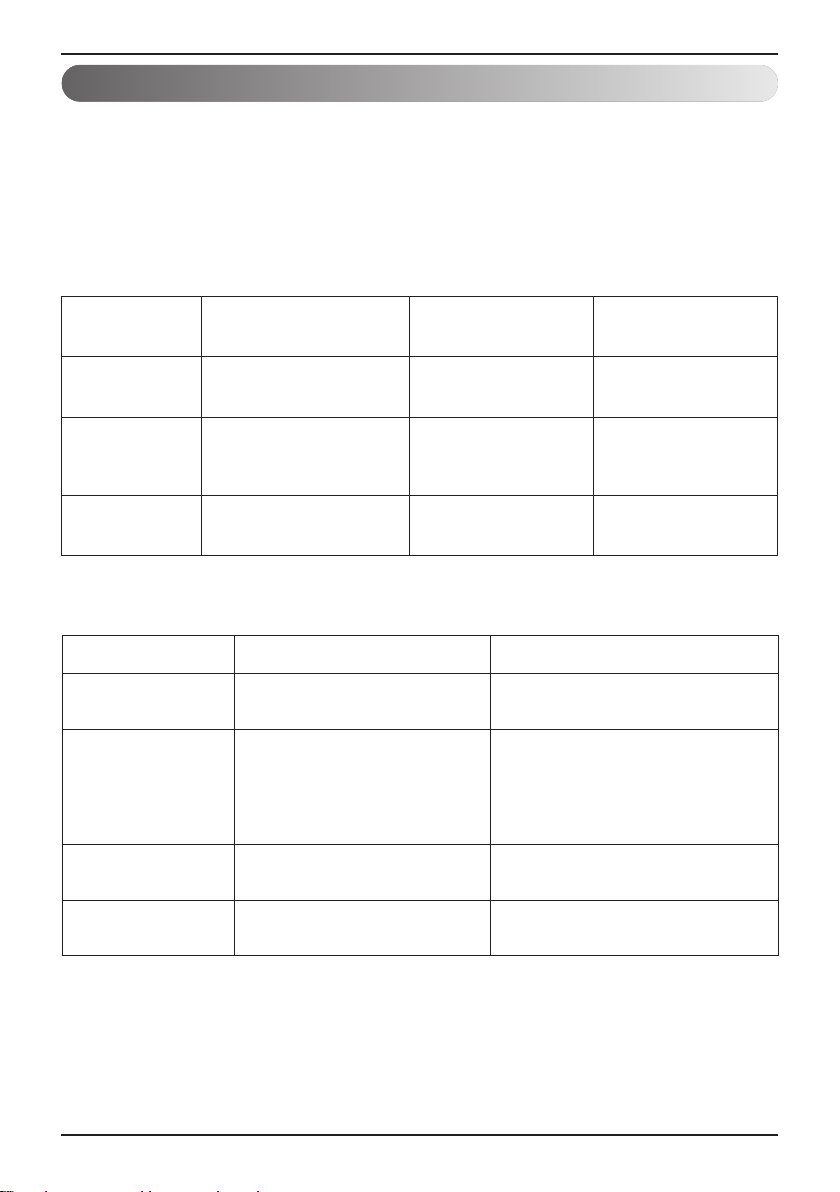
Accessories supported by LG Electronics
Item Purpose
Remote Air
Sensor
Dry Contact
Solar Thermal Kit
To control the unit by air
To receive on & off external
To operate with sanitary
temperature
signal
water tank
Model
(Medium Temperature)
PQRSTA0 PQRSTA0
PDRYCB000 /
PDRYCB100 /
PDRYCB300
PHLLA
Model
(High Temperature)
PDRYCB000 /
PDRYCB100 /
PDRYCB300
Accessories supported by 3rdparty Companies
Item Purpose Specification
Solar
Thermal System
Thermostat
3way valve
and actuator
To generate auxiliary
heating energy for water tank
To control the unit by air
temperature
To control water flow for hot
water heating or floor heating
Heating-Only type
(230 V AC or 24 V AC)
Cooling/Heating type
(230 V AC or 24 V AC
with Mode selection switch)
3 wire, SPDT (Single Pole Double
Throw) type, 230 V AC
2way valve
and actuator
12
Hydro Kit
To control water flow for
Fan Coil Unit
2 wire, NO(Normal Open) or NC
(Normal Closed) type, 230 V AC
Installation
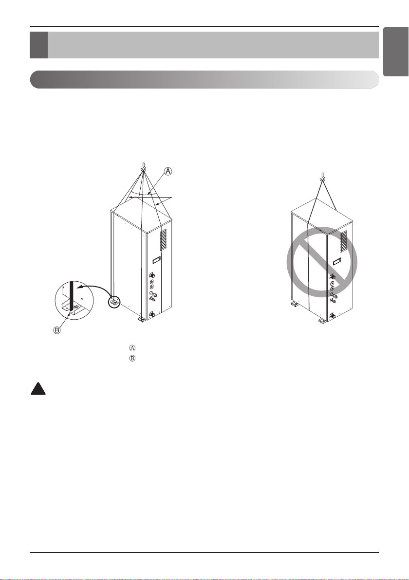
Installation
Transporting the Unit
• For High Temperature
• When carrying the suspended unit, pass the ropes between legs of base panel under the unit.
• Always lift the unit with ropes attached at 6 points so that impact is not applied to the unit.
• Attach the ropes to the unit at an angle Ⓐ of 40° or less.
• Use only accessories and parts which are of the designated specification when installing.
Sub line
ENGLISH
40º or less
Line supporter
!
CAUTION
Be very careful while carrying the unit.
- Do not have only one person carry the unit if it is more than 20 kg (44.1 lbs).
- PP bands are used to pack some products. Do not use them as a mean for transportation
because they are dangerous.
- Tear plastic packaging bag and scrap it so that children cannot play with it. Otherwise
plastic packaging bag may suffocate children to death.
- When carrying the unit, be sure to support it at 6-points. Carrying and lifting the unit with 4point support may make it unstable, resulting in a fall.
Hydro Kit
Installation Manual 13
Installation
Selection of the best location
Select space for installing the unit, which will meet the following conditions:
The place where the unit shall be installed inside.
The place shall easily bear a load exceeding four times of the unit weight.
The place where the unit shall be leveled.
The place shall allow easy water drainage.
The place where the unit shall be connected to the outdoor unit.
The place where the unit is not affected by an electrical noise.
The place where there should not be any heat source or steam near the unit.
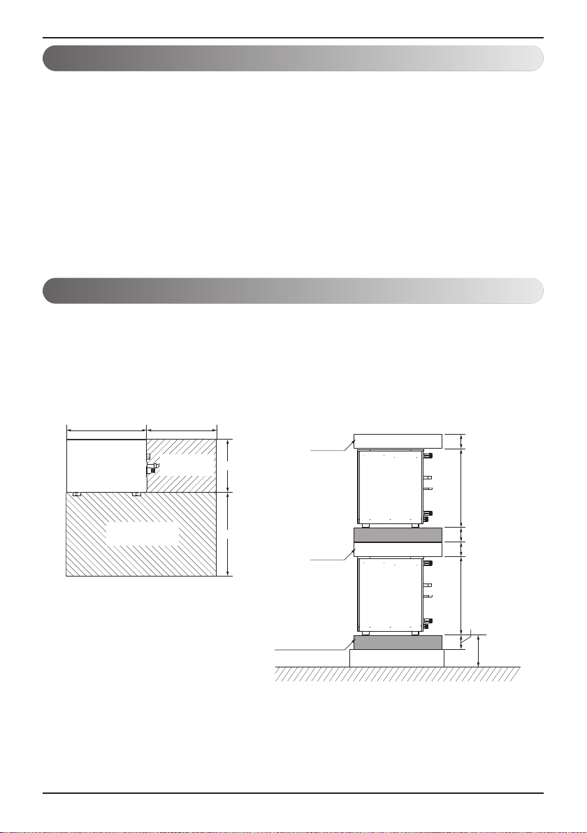
Installation Space
• The following values are the least space for installation.
If any service area is needed for service according to field circumstance, obtain enough service
space.
• The unit of values is mm(inch).
<For Medium Temperature>
520(20-15/32) 400(15-3/4)
Product
Piping space
(front side)
space
330(13)
(Unit: mm(inch))
100(3-15/16)
14
Hydro Kit
Service space
(front side)
600(23-5/8)
(Unit: mm(inch))
space
H-Beam supporter
631(24-16/19)631(24-16/19)
100(3-15/16)
100(3-15/16)
100(3-15/16)
200(7-7/8)
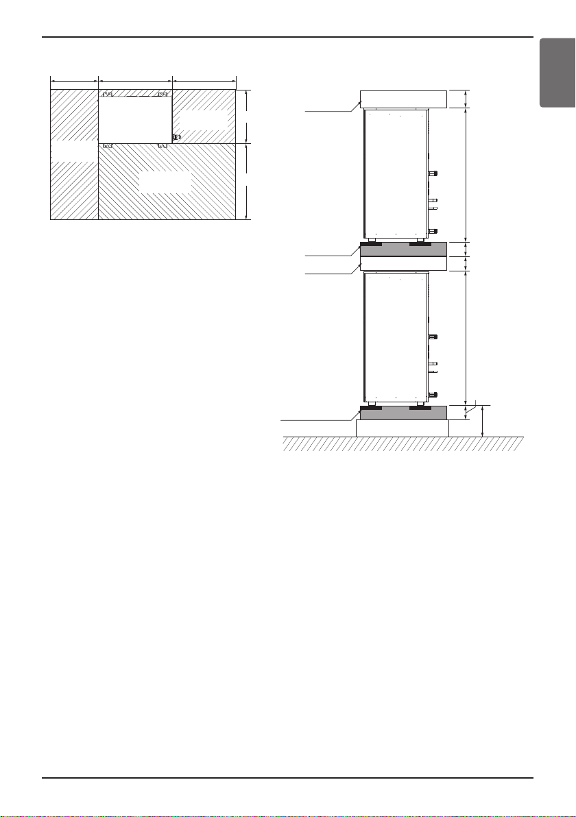
<For High Temperature>
300(11-13/16)
Service space
(left side)
Service space
(front side)
400(15-3/4)520(20-15/32)
Piping space
(front side)
350(13-25/32)
600(23-5/8)
space
Installation
ENGLISH
(Unit : mm(inch))
100(3-15/16)
1 074(42-9/32)1 074(42-9/32)
(Unit : mm(inch))
Anti Vibration
material
space
H-Beam supporter
Concrete supporter
100(3-15/16)
100(3-15/16)
100(3-15/16)
200(7-7/8)
Hydro Kit
Installation Manual 15

Installation
Minimum floor area
(for R32)
- The appliance shall be installed, operated and stored in a room with a floor area larger than the
minimum area.
- Use the graph of table to determine the minimum area.
Amin (m2)
- m : Total refrigerant amount in the system.
- Total refrigerant amount : factory refrigerant charge + additional refrigerant amount.
- Amin : minimum area for installation.
600
500
400
300
200
100
0
0 1.224 2 3 4 5 6 7 8
Floor standing
Wall mounted
Ceiling mounted
m (kg)
Floor location
m (kg) Amin (m
< 1.224
1.224
1.4 16.82
1.6 21.97
1.8 27.80
2 34.32
2.2 41.53
2.4 49.42
2.6 58.00
2.8 67.27
3 77.22
3.2 87.86
3.4 99.19
3.6 111.20
3.8 123.90
4 137.29
4.2 151.36
4.4 166.12
16
Hydro Kit
-
12.9
Floor location
2
)
m (kg) Amin (m
4.6 181.56
4.8 197.70
5 214.51
5.2 232.02
5.4 250.21
5.6 269.09
5.8 288.65
6 308.90
6.2 329.84
6.4 351.46
6.6 373.77
6.8 396.76
7 420.45
7.2 444.81
7.4 469.87
7.6 495.61
7.8 522.04
2
)
Wall mounted
m (kg) Amin (m
< 1.224
1.224
1.4 1.87
1.6 2.44
1.8 3.09
2.2 4.61
2.4 5.49
2.6 6.44
2.8 7.47
3.2 9.76
3.4 11.02
3.6 12.36
3.8 13.77
4.2 16.82
4.4 18.46
-
1.43
2 3.81
3 8.58
4 15.25
Wall mounted
2
)
m (kg) Amin (m
4.6 20.17
4.8 21.97
5 23.83
5.2 25.78
5.4 27.80
5.6 29.90
5.8 32.07
6 34.32
6.2 36.65
6.4 39.05
6.6 41.53
6.8 44.08
7 46.72
7.2 49.42
7.4 52.21
7.6 55.07
7.8 58.00
2
)
Ceiling Mounted
m (kg) Amin (m
< 1.224
1.224
1.4 1.25
1.6 1.63
1.8 2.07
2.2 3.09
2.4 3.68
2.6 4.31
2.8 5.00
3.2 6.54
3.4 7.38
3.6 8.27
3.8 9.22
4.2 11.26
4.4 12.36
-
0.956
2 2.55
3 5.74
4 10.21
Ceiling Mounted
2
)
m (kg) Amin (m
4.6 13.50
4.8 14.70
5 15.96
5.2 17.26
5.4 18.61
5.6 20.01
5.8 21.47
6 22.98
6.2 24.53
6.4 26.14
6.6 27.80
6.8 29.51
7 31.27
7.2 33.09
7.4 34.95
7.6 36.86
7.8 38.83
2
)
Installation
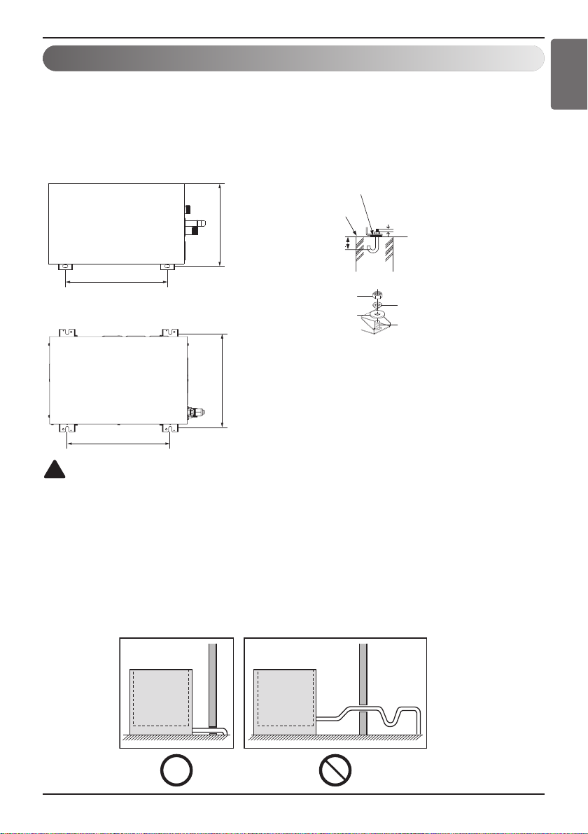
Flat washer
Anchor bolt
Spring washer
Nut
Anti-vibration material
Concrete base
Support
75(2-15/16)
3 or more screw threads of
the 2 bolts must be shown
(Unit: mm(inch))
392(15-7/16)
340(13-3/8)
360(14-3/16)
(Unit: mm(inch))
392(15-7/16)
ENGLISH
Foundation for Installation
• Fix the unit tightly with bolts as shown below so that the unit will not fall down due to earthquake.
• Noise and vibration may occur from the floor or wall since vibration is transferred through the
installation part depending on installation status. Thus, use anti-vibration materials (cushion pad)
fully (The base pad shall be more than 200 mm (7-7/8 inch)).
<For Medium Temperature>
<For High Temperature>
!
CAUTION
• When mechanical connectors are reused indoors, sealing parts shall be renewed. (for R32)
• When flared joints are reused indoors, the flare part shall be re-fabricated. (for R32)
Drain pipe connection (For Medium Temperature)
-
Hydro Kit
- Do not install in upward direction.
- Install the drain pipe in downward direction (1/50-1/100).
-
Hydro Kit
does not use the drain pump.
drain connection pipe is PT 1.
Hydro kit Hydro kit
Hydro Kit
Installation Manual 17
Installation
Water Piping and Water Circuit Connection
General Considerations
Followings should be considered before beginning water circuit connection.
• Service space should be secured.
• Water pipes and connections should be cleaned using water.
• Space for installing external water pump should be provided.
• Never connect electric power while proceeding water charging.
Water Piping and Water Circuit Connection
While installing water pipes, followings should be considered :
While inserting or putting water pipes, close the end of the pipe with pipe cap to avoid dust entering.
•
• When cutting or welding the pipe, always be careful that inner section of the pipe should not be
defective. For example, no weldments or no burrs are found inside the pipe.
• Pipe fittings (e.g. L-shape elbow, T-shape tee, diameter reducer, etc) should be tightened strongly
to be free from water leakage.
• Connected sections should be leakage-proof treatment by applying tefron tape, rubber bushing,
sealant solution, etc.
Appropriate tools and tooling methods should be applied to prevent mechanical breakage of the connections.
•
• Operation time of flow valve(e.g. 3way valve or 2way valve) should be less than 90 seconds.
• Pipe is insulated to prevent heat loss to external environment.
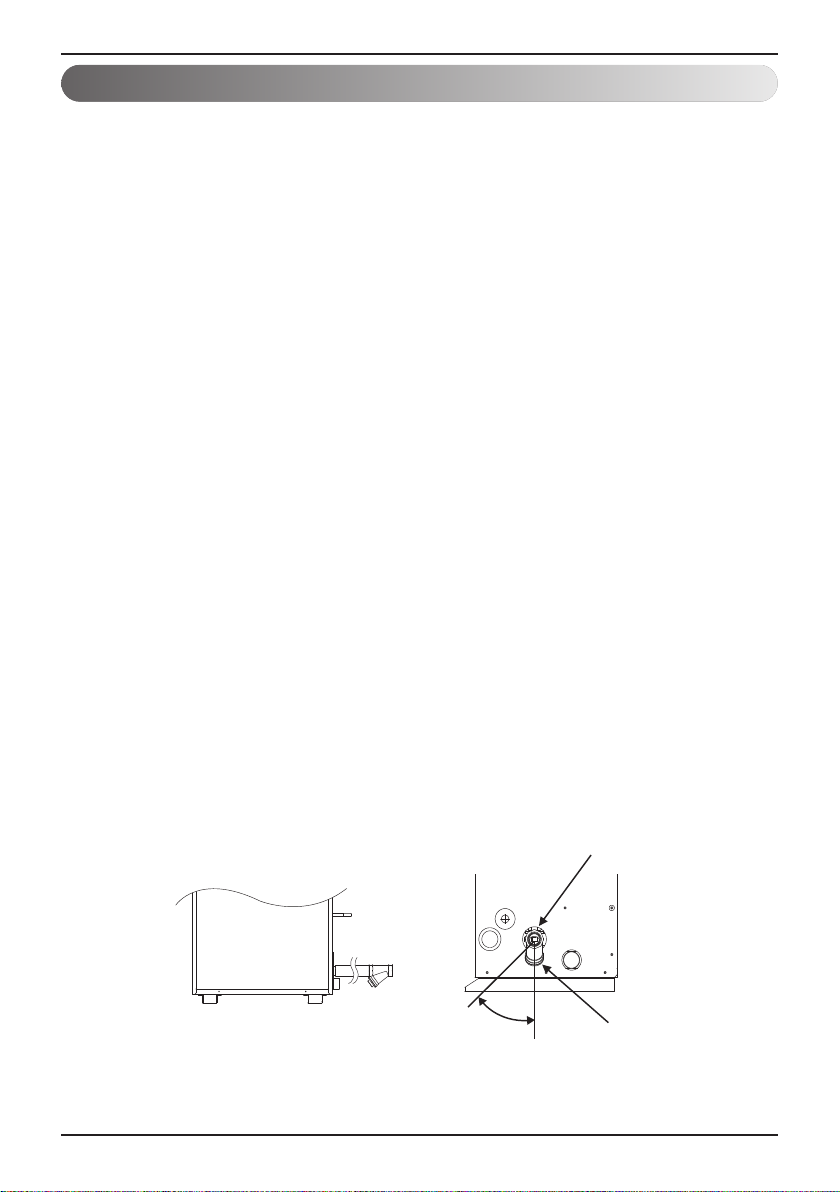
Strainer
- Use the 30 mesh strainer. (Exclude scale diameter of 0.8 mm or less and other net)
- Check the strainer direction and assemble on the inlet hole (Refer to picture)
- Wrap the Teflon tape on the screw thread of the water pipe for more than 15 times for assembly.
- Install the service port facing downward. (Within left/right 45 degrees)
- Check if there is any leakage on the connecting part.
- Clean the strainer periodically. (Once a year or more frequent)
Water In
18
Hydro Kit
Front
45°
Side
Strainer

Installation
Water cycle minimum requirements
1. For selecting the components of the hydraulic system, be sure they are above the design water
pressure.
2. For the water pipe, diffusely tight water pipes are recommended instead of steel pipes.
3. For the drain pipe size, use the same diameter as the product connected or larger. Always install a
natural drainage so that the drained water does not flows back
4. Install insulated material across the total hydraulic piping to prevent condensation and to prevent
low cooling or heating capacity during heat transfer losses. If the temperature is higher than 30 °C
and the humidity is higher than 80 % the insulation material must be minimum 20 mm thick to
prevent condensation.
5. Install the shut-off valve (1) to block the water by closing the valve when replacing the component
or cleaning.
6. Install an expansion tank (2) based on the water volume of the hydraulic system.
7. Install the drain valve (3) that can be used for draining the water inside when replacing the
component or providing service.
8. Install a magnetic dirt separator (4) at the inlet water pipe If the air separator is not installed there
can be formed air bubbles inside the hydraulic system. Flow error will be showed first on remote
controller, however finally a plate heat exchanger may burst during combined circumstances.
9. Install a circulation pump (5) which meets the water flow specifications mentioned inside product
data book.
10. Install the strainer (6) at the inlet water pipe connection to protect the PHE. Do not charge water
into the water pipe directly during Hydro Kit operation. If the strainer is not installed, component
malfunction of Hydro Kit may occur.
- For the strainer, use one with 30 mesh or above with measurement diameter of 0.8 mm or less.
- Always install the strainer on the horizontal pipe.
11. Install a balancing valve (with flow meter) (8)
12. Install an automatic air separator in the outlet water pipe (9)
13. Install pressure safety relief valve (10) in vertical upright position that meets the design water
pressure to prevent unit or water pipe damage during pressure increase inside the water pipe
system.
14. Install a pressure meter (11) in the outlet water pipe.
15. Install in case of cascade hydraulic systems or bivalent systems a flow-check valve (12) at each
outlet water pipe.
16. Install a buffer tank (13) of at least 10L/kW heating capacity in order to have a correct defrost
cycle, if there is no knowledge about the type and dimensions of the heating system. If there is
no buffer tank installed, the product can be damaged during normal operation or defrost
operation.
17. After product operation for 2 weeks in case of new installation, clean the water filter. In the
beginning of operation small particular dirt from installing process can block the filter which can
lead to damage of the product.
ENGLISH
Hydro Kit
Installation Manual 19
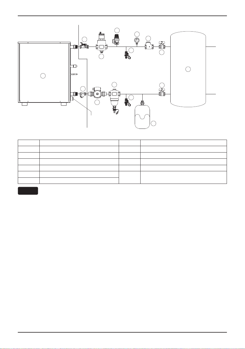
Installation
Field SupplyLG Supply
8
7
6
5
Drainage
10
9
4
11
12
3
3
1
13
1
2
1 Shut-Off valve 8 Balancing valve with flow meter
2 Expansion tank 9 Automatic air separator
3 Service port(Drain valve) 10 Pressure safety relief valve
4 Magnetic filter(Recommended) 11 Pressure meter
5 Water Pump 12 Check valve
6 Strainer
7 Flow switch (included in product)
Buffer tank /
13
DHW1)(Sanitary Water) Tank
NOTE
Install the closed loop type water pipe system.
Balancing valve with flow meter is recommended to ensure 100 % of the nominal flow.
1)
DHW : Domestic Hot Water.
Heating
/
Cooling
20
Hydro Kit
Installation
Installation Scenes
Installation scenes are presented for example.
Installer should optimize the installation scene according to the installation conditions and
local/national regulation.
i.e. Shut-off valves position for spare water pump and water pump service, Flexible joint
installation to prevent noise and vibration.
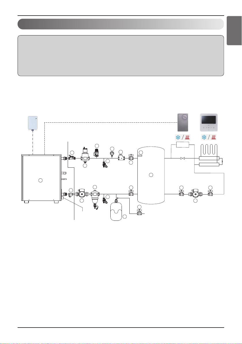
1) Space Heating/Cooling1)Installation
ENGLISH
Wi-fi Module
(PWFMDD200)
7
Field SupplyLG Supply
8
6
9
5
Drainage
Remote temperature
sensor(PQRSTA0)
10
11
12
3
4
3
14
1
13
1
1
2
Water Supply
FCU
(Cooling → Close)
1
Wired Remote
Controller
1
5
Hydro Kit
Installation Manual 21
Installation
1 Shut-Off valve 8 Balancing valve with flow meter
2 Expansion tank 9 Automatic air separator
3 Service port(Drain valve) 10 Pressure safety relief valve
Magnetic filter (Mandatory with
4
Corrosive material of pipe)
11 Pressure meter
5 Water Pump 12 Check valve
6 Strainer 13 Buffer Tank
7 Flow switch (included in product) 14 Water Tank temperature Sensor (12 m)
- For space heating / cooling, ‘DIP switch #2’ should be set correctly.
- For sensing air temperature at specific area, remote temperature sensor(PQRSTA0) or wired
remote controller could be choose, depending on the ‘DIP switch #3’ setting.
*please refer the “System Set-Up, DIP Switch Setting”
- Wi-Fi module(PWFMDD200/105 cm) connected to ‘CN-WF’ on Hydro kit PCB. To increase the
length between Wi-Fi modem and Hydro Kit, please purchase USB Extension Cable(PWYREW000,
10 m)
- In case of floor cooling, please make sure to set cooling cut off temperature for preventing
condensation on the floor
- For 2 way valve control, please refer the “Accessories Installation, 2 Way valve”
Mode Condition 2-way valve
Cooling
FCU – ‘Not use’ Open
FCU – ‘Use’ Close
Heating None No control
NOTE
- Balancing valve with flow meter is recommended to ensure 100 % of the nominal flow.
If the water flow rate is too low or High, PHEX could be frozen and burst or capacity could be
reduced.
1)
Cooling operation is only available for Medium temperature Hydro Kit.
22
Hydro Kit

Installation
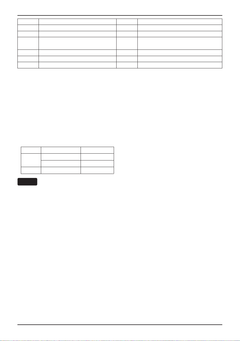
2) Water Tank(DHW) Installation
Wi-fi Module
(PWFMDD200)
Field SupplyLG Supply
8
7
6
9
5
Drainage
10
11
12
3
4
3
2
Wired Remote
Controller
13
14
1
1
1
Water Supply
1 Shut-Off valve
2 Expansion tank
3 Service port(Drain valve)
Magnetic filter (Mandatory with
4
Corrosive material of pipe)
5 Water Pump
6 Strainer
7 Flow switch (included in product)
8 Balancing valve with flow meter
9 Automatic air separator
10 Pressure safety relief valve
11 Pressure meter
12 Check valve
1
13 Buffer Tank
14 Water Tank temperature Sensor (12 m)
ENGLISH
- For water tank(DHW) operation, DIP switch #2 in Hydro Kit PCB should be set correctly, please
refer the “System Set-Up, DIP Switch Setting”
- Wi-Fi module(PWFMDD200, 105 cm) is connected to ‘CN-WF” on Hydro Kit PCB.
To increase the length between Wi-Fi modem and Hydro Kit, please purchase USB Extension
Cable(PWYREW000, 10 m)
- DHW(Sanitary water) tank should be located at the flat place.
- Water quality should comply with EN 98/83 EC Directives.
- DHW(Sanitary water) tank (indirect heat exchange), do not use anti water-freezing treatment like
ethylene glycol.
- It is highly recommend to wash out inside of the DHW(Sanitary water) tank after installation for
clean hot water.
- Near the DHW(Sanitary water) tank , there should be water supply and water drain for easy access
and maintenance.
Water tank temperature sensor(14) connection
If hot water mode is used, make sure to install sensor to
Process PT 1/2 inch
female bolt
water tank.
• Make PT 1/2inch female bolt hole in the water tank and
install sensor in the water tank.
Water Tank
Temperature Sensor
PT 1/2 inch male
Sensor
holder
Inside
water tank
Water tank outer wall
• Push the sensor into the hole of the sensor holder cap.
• Lock the sensor holder cap.
• Maximum length of water tank temperature sensor is 12 m.
Hydro Kit
Installation Manual 23
Installation
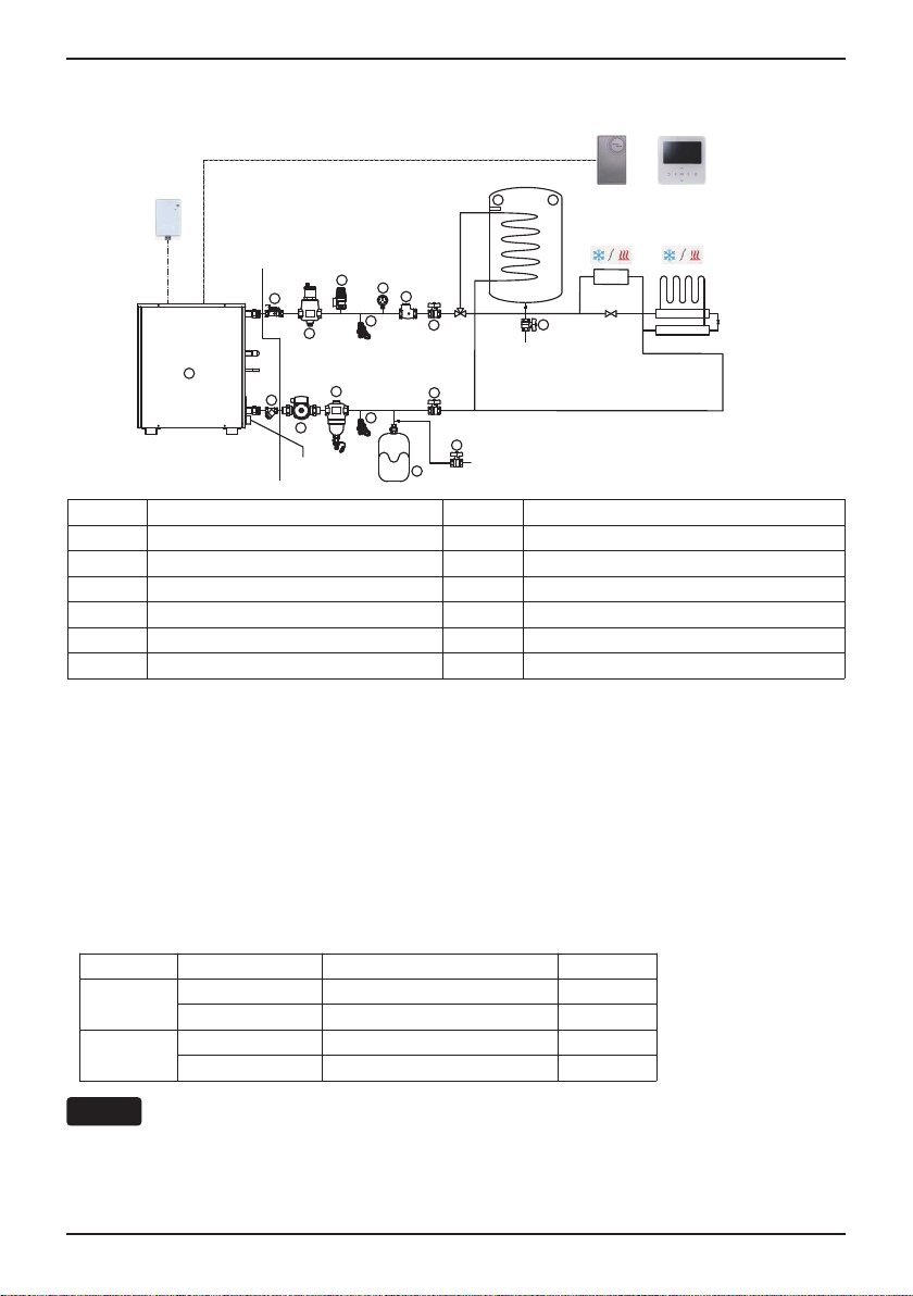
3) Water Tank(DHW) + Floor Heating Installation(Default)
Remote temperature
sensor(PQRSTA0)
Wi-fi Module
(PWFMDD200)
LG Supply
Field Supply
8
9
7
6
5
Drainage
1
Shut-Off valve
2
Expansion tank
3
Service port(Drain valve)
4
Magnetic filter(Recommended)
5
Water Pump
6
Strainer
7
Flow switch (Included in product)
10
11
12
3
4
3
2
1
1
1
14
13
FCU
(Cooling → Close)
1
Water Supply
Water Supply
8
Balancing valve with flow meter
9
Automatic air separator
10
Pressure safety relief valve
11
Pressure meter
12
Check valve
13
DHW1)(Sanitary Water) Tank
14
Water Tank temperature Sensor (12 m)
Wired Remote
Controller
- For DHW / Floor Heating operation , ‘DIP switch #2’ should be set correctly.
- For sensing air temperature at specific area, remote temperature sensor(PQRSTA0) or wired
remote controller could be choose, depending on the ‘DIP switch #3’ setting.
*please refer the “System Set-Up, DIP Switch Setting”
- Wi-Fi module(PWFMDD200/105 cm) connected to ‘CN-WF’ on Hydro kit PCB. To increase the
length between Wi-Fi modem and Hydro Kit, please purchase USB Extension Cable(PWYREW000,
10 m)
- In case of floor cooling, please make sure to set cooling cut off temperature for preventing
condensation on the floor
- For 3-way, 2-way valve control, please refer the “Accessories Installation”
Mode Condition 3-way valve direction 2-way valve
Cooling
Heating
FCU – ‘Not use’ Under Floor Open
FCU – ‘Use’ Under Floor Close
Priority – ‘DHW’ DHW / Sanitary Water Tank No control
Priority – ‘UFH’ Under Floor No control
NOTE
- The Heating operation mode of the hot water tank is not a mode selection by the remote controller,
it changes the 3-way valve direction to Water Tank base on the water tank temperature.
- It is impossible to operate Hot water(DHW) during cooling mode.
24
Hydro Kit
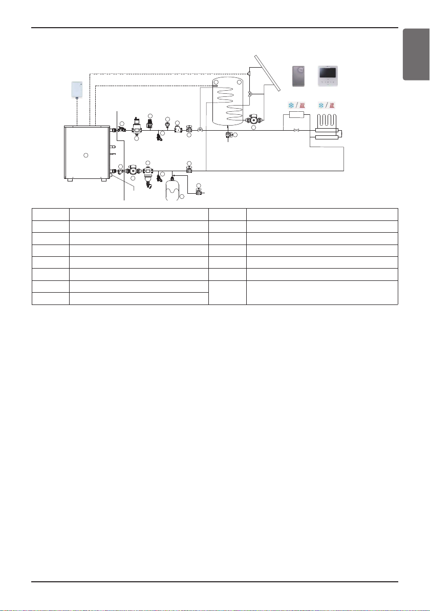
4) Water Tank(DHW) + Floor Heating + Solar booster Installation
13
12
1
1
Field Supply
LG Supply
3
3
11
10
9
8
6
5
4
2
7
Drainage
1
Water Supply
FCU
14
(Cooling → Close)
Wired Remote
Controller
Wi-fi Module
(PWFMDD200)
5
1
Water Supply
Remote temperature
sensor(PQRSTA0)
1
Shut-Off valve
2
Expansion tank
3
Service port(Drain valve)
4
Magnetic filter(Recommended)
5
Water Pump
6
Strainer
7
Flow switch (Included in product)
8
Balancing valve with flow meter
9
Automatic air separator
10
Pressure safety relief valve
11
Pressure meter
12
Check valve
13
DHW1)(Sanitary Water) Tank
14
Water Tank temperature Sensor (12 m)
15
Solar panel
Installation
ENGLISH
- For DHW / Floor Heating and Solar booster operation , ‘DIP switch #2’ should be set correctly.
- For sensing air temperature at specific area, remote temperature sensor(PQRSTA0) or wired
remote controller could be choose, depending on the ‘DIP switch #3’ setting.
*please refer the “System Set-Up, DIP Switch Setting”
- Wi-Fi module(PWFMDD200/105cm) connected to ‘CN-WF’ on Hydro kit PCB. To increase the
length between Wi-Fi modem and Hydro Kit, please purchase USB Extension Cable(PWYREW000,
10 m)
- In case of floor cooling, please make sure to set cooling cut off temperature for preventing
condensation on the floor
- DHW(Sanitary water) tank should be located at the flat place.
- Water quality should comply with EN 98/83 EC Directives.
- DHW(Sanitary water) tank (indirect heat exchange), do not use anti water-freezing treatment like
ethylene glycol.
- It is highly recommend to wash out inside of the DHW(Sanitary water) tank after installation for
clean hot water.
- Near the DHW(Sanitary water) tank , there should be water supply and water drain for easy access
and maintenance.
- For 2-way or 3-way valve control, please refer the “Accessories Installation”.
Hydro Kit
Installation Manual 25
 Loading...