

LG AR7314S Diagram
INSTALLATION INSTRUCTIONS
SINGLE SPLIT WALL MOUNTED AIR CONDITIONER
More than
10cm
More than 70cm
More than
60cm
More than
10cm
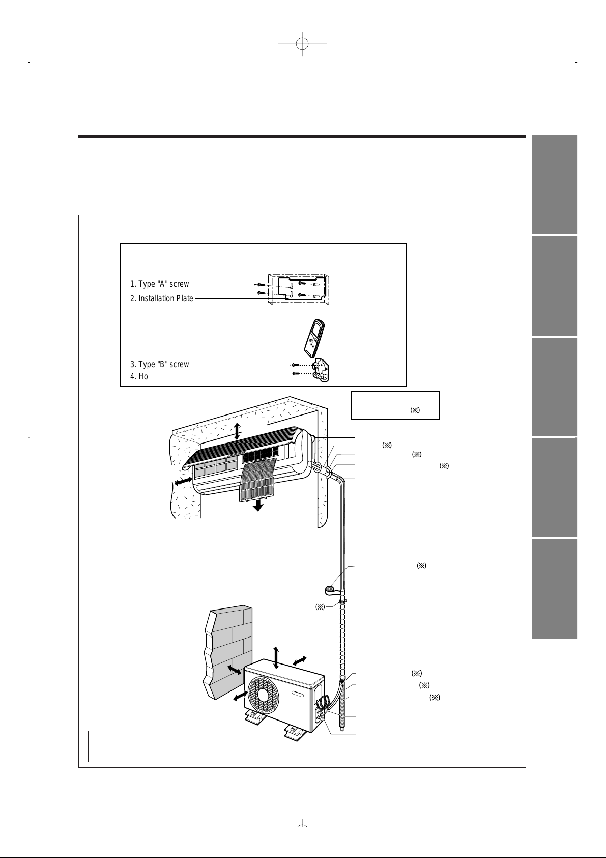
Gas side piping
Liquid side piping
Additional drain pipe
Vinyl tape (Narrow)
Connecting cable:
Cooling & Heat pump: 2EA
Cooling only: 1EA
,,,
,,,
yyy
yyy
{{{
1. Type "A" screw
2. Installation Plate
3. Type "B" screw
4. Holder Remote Control
Air filter
(Left and right
are identical)
Installation plate
Sleeve
Bushing-Sleeve
Putty(Gum Type Sealer)
Bend the pipe as closely
on the wall as possible,
but be careful that it
doesn't break.
Installation parts you
must purchase
Vinyl tape (Wide)
• Apply after carrying out a
drainage test.
• To carry out the drainage
test, remove the air filters
and pour water into the heat
exchanger.
Saddle
More than
5cm
More than
5cm
P/No. : 3828AR7314S
(SK-Series)
• Please read this instruction sheet completely before installing the product.
• When the power cord is damaged, replacement work shall be performed by authorized
personnel only.
• Installation work must be performed in accordance with the national wiring standards by
authorized personnel only.
Installation Parts Provided
• This illustration is for explanation purposes only.
The indoor unit will actually face a different way.
ENGLISH ITALIANO ESPAÑOL FRANÇAIS DEUTSCH
INSTALLATION OVERVIEW
2
Thefollowingshould bealways
observedfor safety
....................
3
Installationof indoor,outdoor
unit
................................................
4
Flaring work andconnection of
piping
...........................................
6
Connectionofpiping(Indoor)
......
7
Forright rear piping
Forleftrearpiping
Connectionofpiping(Outdoor)
................................................
10
Connecting thecable between
indoorunitandoutdoorunit
......
....................................................
11
Checkingthe drainageand
Forming thepiping
..................
13
Airpurging
...............................
14
Test running
.............................
16
❏Installationplate
❏Fourtype"A"screws
❏Connectingcable
❏Pipes:Gasside
...........
1/2",5/8"
Liquidside
........
1/4",3/8"
(Referto page 4)
❏Insulationmaterials
❏Additionaldrainpipe
(OuterDiameter
...........
15.5mm)
❏Two type"B"screws
❏Levelgauge
❏Screwdriver
❏Electricdrill
❏Holecoredrill(ø70mm)
❏Flaringtoolset
❏Specified torquewrenches
1.8kg.m,4.2kg.m,5.5kg.m,6.6kg.m
(differentdepending onmodelNo.)
(Referto page10)
❏Spanner......................Halfunion
❏A glassof water
❏Screwdriver
❏Hexagonal wrench(4mm)
❏Gas-leakdetector
❏Vacuumpump
❏Gaugemanifold
❏Owner'smanual
❏Thermometer
❏Holder RemoteControl
Installation
Requirements
Required Parts Required Tools
ENGLISH
THE FOLLOWING SHOULD BE ALWAYS OBSERVED FOR SAFETY
3
■
Be sure to read "THE FOLLOWING SHOULD BE ALWAYS OBSERVED FOR SAFETY" before installing the air
conditioner.
■
Be sure to observe the cautions specified here as they include important items related to safety.
■
The indications and meanings are as follows.
■
After reading this instructions, be sure to keep it together with the owner's manual in a handy place on the
customer's site.
WARNING
: Could lead to death, serious injury, etc.
CAUTION
: Could lead to serious injury in particular environments when operated
incorrectly.
WARNING
Incorrect installation could cause injury due to fire,
electric shock, the unit falling or leakage of water.
Consult the dealer from whom you purchased the
unit or special installer.
Do not install it yourself (customer).
When installed in an insufficiently strong place,
the unit could fall causing injury.
Install the unit securely in a place which can bear
the weight of the unit.
Incorrect connection and fixing could cause fire.
Use the specified wires to connect the indoor and
outdoor units securely and attach the wires firmly
to the terminal board connecting sections so the
stress of the wires is not applied to the sections.
If the electrical part cover of the indoor unit and/or
the service panel of the outdoor unit are not
attached securely, it could result in a fire or
electric shock due to dust, water, etc.
Attach the electrical part cover to the indoor unit
and the service panelto the outdoorunit securely.
The use of defective parts could cause an injury
due to a fire, electric shock, the unit falling, etc.
Be sure to use the part provided or specified parts
for the installation work.
Check that the refrigerant gas does not leak after
installation is completed.
Incorrect installation could cause a personal
injury due to fire, electric shock, the unit falling
or leakage of water.
Perform the installation securely referring to the
installation instruction.
If the capacity of the power circuit is insufficient
or there is incomplete electrical work, it could
result in a fire or an electric shock.
Perform electrical work according to the installation
manualandbe sureto usean exclusivecircuit.
CAUTION
If there is a defect in the drainage/piping work,
watercouldleak from the unit and household
goods couldget wet and be damaged.
Perform the drainage/pipingworkaccording
tothe installationinstruction.
If gas leaks and accumulatesin the area
surrounding the unit, it could cause an explosion.
Donot install theunitin a place wherean
inflammablegas leaks.
4
INSTALLATION OF INDOOR, OUTDOOR UNIT
Read completely,thenfollowstepby step.
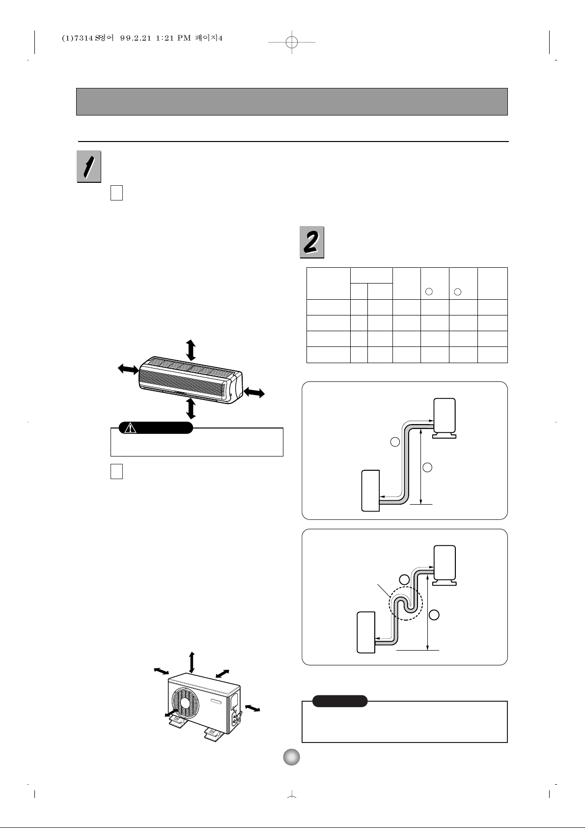
Select the best location
Indoor unit
■
Do not have any heat or steam near the
unit.
■
Select a place where there are no
obstaclesinfrontof theunit.
■
Make sure that condensation drainage
canbe convenientlyroutedaway.
■
Donot install near a doorway.
■
Ensurethatthespacearoundthe leftand
right of the unit is more than 5cm. The
unit should be installed as high on the
wall as possible, allowing a minimum of
5cmfromceiling.
■
Use a stud finder to locate studs to
preventunnecessarydamageto thewall.
Outdoor unit
■
If an awning is built over the unit to
prevent direct sunlight or rain exposure,
make sure that heat radiation from the
condenserisnot restricted.
■
Ensure that the space around the back
andsidesis more than 10cm. Thefrontof
the unit should have more than 70cm of
space.
■
Donot placeanimalsand plantsin the
path ofthe warm air.
■
Take theairconditionerweightinto
accountand selecta placewhere noise
andvibrationare minimum.
■ Select a place so that the warm air and
noise from the air conditioner do not
disturb neighbors.
■
Rooftop Installations:
Ifthe outdoor unit isinstalled ona roofstructure,be
sure toleveltheunit.Ensurethe roof structureand
anchoringmethodareadequateforthe unitlocation.
Consultlocalcodesregardingrooftopmounting.
Piping length and elevation
More than 5cm
More than 5cm
More than 2.3m
More than 5cm
More than 10cm More than 10cm
More
than 60cm
More than 60cm
More than 70cm
Incasemorethan5m
A
B
• Capacity is based on standard length and maximum
allowance length is on the basis of reliability.
• Oil trap should be installed every 5~7 meters.
Outdoor unit
Indoor unit
A
B
A
Oil trap
Outdoor unit
Indoor unit
B
CAUTION
Install the indoor unit on the wall where the height
from the floors more than 2.3 meters.
CAUTION
18K(60Hz) 5/8" 1/4" 4 or 5 10 20 20
18K(50Hz) 1/2" 1/4" 4 or 5 15 30 30
24K(60Hz) 5/8" 1/4" 4 or 5 15 30 30
24K(50Hz) 5/8" 3/8" 4 or 5 15 30 30
Pipe Size
Capacity
(Btu/h)
GAS LIQUID
Max.
length
A (m)
Additional
Refrigerant
(g/m)
Max.
Elevation
B (m)
Standard
Length
(m)
ENGLISH
5
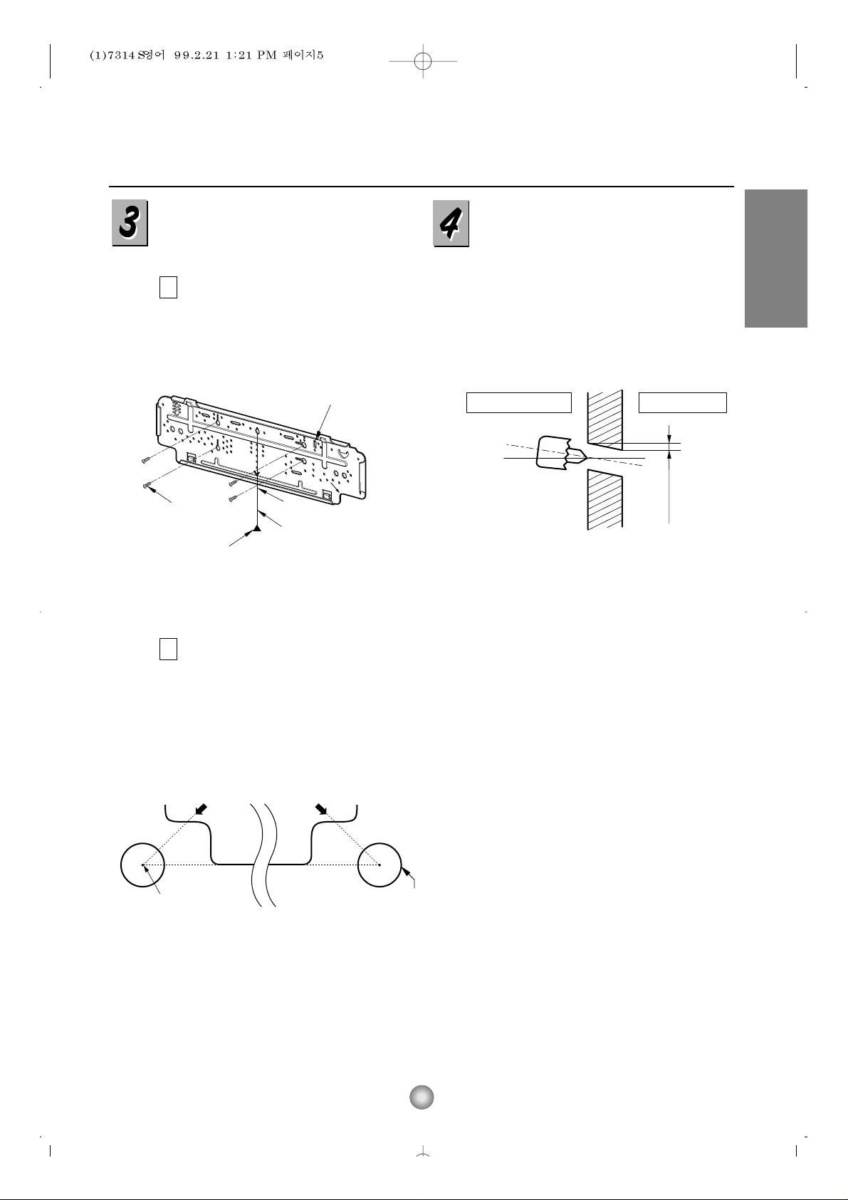
How to fix installation plate
Thewallyouselect shouldbe strongandsolid
enoughto preventvibration
Mountthe installationplateon thewallwith
four type A screws. Ifmountingtheuniton a
concretewall,useanchorbolts.
■
Mountthe installationplatehorizontallyby
aligningthecenterlineusinga level.
Measure thewallandmarkthe centerline.It
isalsoimportant touse caution concerning
thelocationof the installationplate-routingof
thewiringto power outlets isthroughthe
wallstypically.Drilling theholethroughthe
wall forpipingconnectionsmustbedone
safely.
5-7mm
(0.2~0.3")
Indoor
WALL
Outdoor
Installation Plate
Marking-off line
Thread
Weight
Type "A" screw
A
B
■
Drillthe pipingholewitha ø70mm hole core
drill.Drillthe pipingholeat eithertherightor
theleftwiththeholeslightlyslantedtothe
outdoorside.
Drill a hole in the wall
Right rear pipingLeft rear piping
"D" "C"
Hole center
ø70mm
 Loading...