

LG 42PQ60R Owner’s Manual

PLASMA TV
OWNER’S MANUAL
42PQ10R
50PQ10R
42PQ20R
42PQ30R
50PQ30R
Please read this manual carefully before operating
your set and retain it for future reference.
The model and serial number of the TV is located
on the back and one side of the TV.
Record it below should you ever need service.
Model:
Serial:
42PQ60R
50PQ60R
50PS80BR
60PS80BR
P/NO : MFL58486302 (0907-REV03)
Printed in Korea
www.lge.com
WARNING / CAUTION
TO REDUCE THE RISK OF ELECTRIC SHOCK
DO NOT REMOVE COVER (OR BACK). NO
USER SERVICEABLE PARTS INSIDE. REFER TO
QUALIFIED SERVICE PERSONNEL.
The lightning flash with arrowhead
symbol, within an equilateral triangle, is
intended to alert the user to the presence
of uninsulated “dangerous voltage” within the
product’s enclosure that may be of sufficient
magnitude to constitute a risk of electric shock to
persons.
The exclamation point within an equilateral
triangle is intended to alert the user to
the presence of important operating and
maintenance (servicing) instructions in the literature accompanying the appliance.
WARNING/CAUTION
TO REDUCE THE RISK OF FIRE AND ELECTRIC
SHOCK, DO NOT EXPOSE THIS PRODUCT TO
RAIN OR MOISTURE.
2
SAFETY INSTRUCTIONS
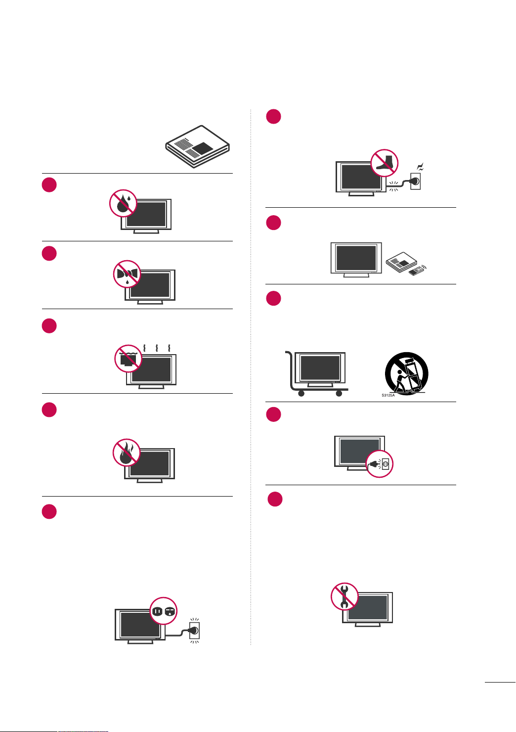
IMPORTANT SAFETY INSTRUCTIONS
Read these instructions.
Keep these instructions.
Heed all warnings.
Follow all instructions.
Do not use this apparatus near water.
1
Clean only with dry cloth.
2
Do not block any ventilation openings. Install in
3
accordance with the manufacturer’s instructions.
Protect the power cord from being walked on
6
or pinched particularly at plugs, convenience
receptacles, and the point where they exit from
the apparatus.
Only use attachments/accessories specified by
7
the manufacturer.
Use only with the cart, stand, tripod, bracket,
8
or table specified by the manufacturer, or sold
with the apparatus. When a cart is used, use
caution when moving the cart/apparatus combination to avoid injury from tip-over.
Do not install near any heat sources such as
4
radiators, heat registers, stoves, or other
apparatus (including amplifiers)that produce
heat.
Do not defeat the safety purpose of the polarized
5
or grounding-type plug. A polarized plug has
two blades with one wider than the other. A
grounding type plug has two blades and a
third grounding prong, The wide blade or the
third prong are provided for your safety. If the
provided plug does not fit into your outlet,
consult an electrician for replacement of the
obsolete outlet.
Unplug this apparatus during lighting storms
9
or when unused for long periods of time.
Refer all servicing to qualified service personnel.
10
Servicing is required when the apparatus has
been damaged in any way, such as powersupply cord or plug is damaged, liquid has
been spilled or objects have fallen into the
apparatus, the apparatus has been exposed to
rain or moisture, does not operate normally, or
has been dropped.
3
SAFETY INSTRUCTIONS
Owner Manual
Never touch this apparatus or antenna during
11
a thunder or lighting storm.
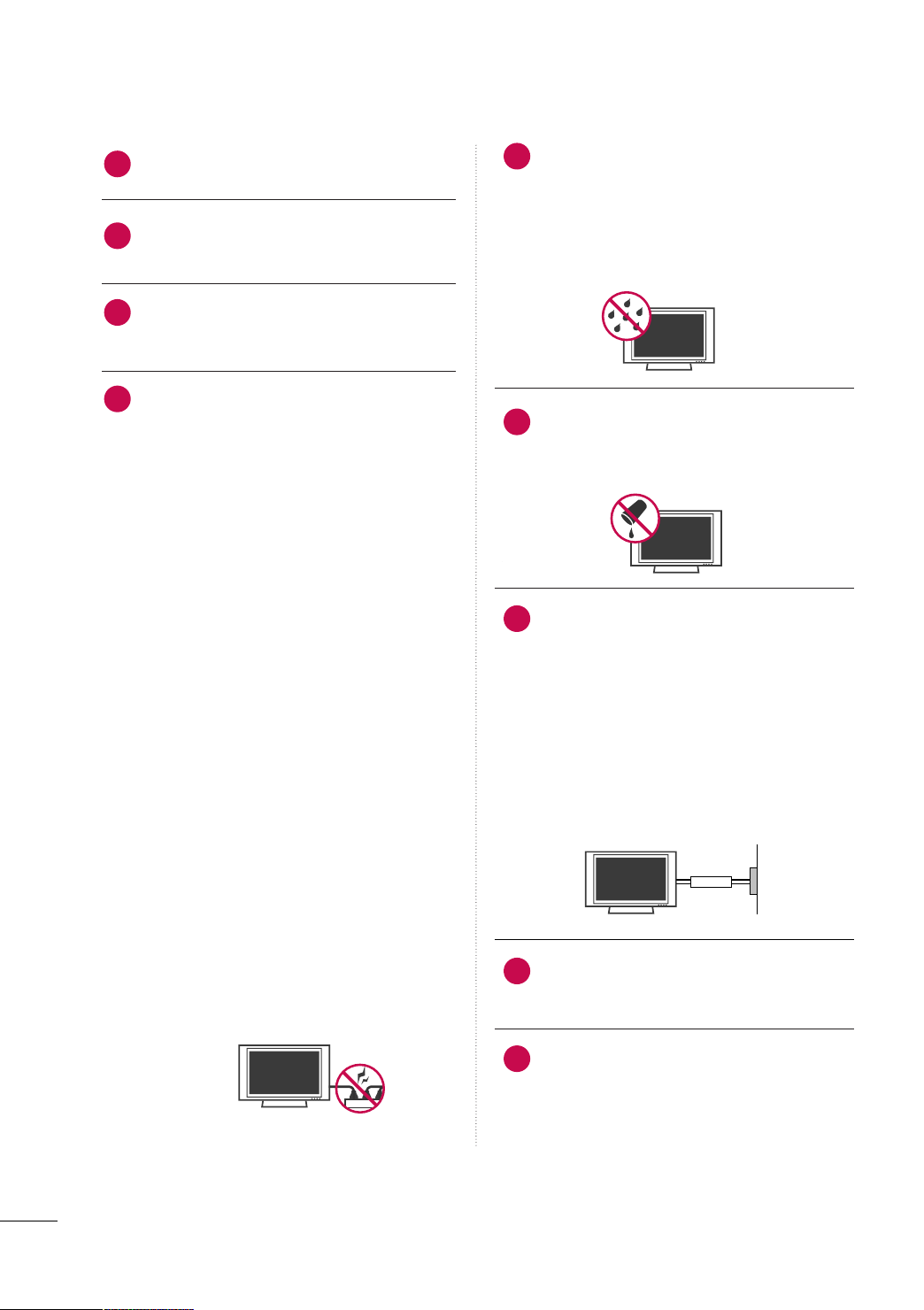
When mounting a TV on the wall, make sure
12
not to install the TV by the hanging power and
signal cables on the back of the TV.
Do not allow an impact shock or any objects to
13
fall into the product, and do not drop onto the
screen with something.
CAUTION concerning the Power Cord:
14
It is recommend that appliances be placed
upon a dedicated circuit; that is, a single
outlet circuit which powers only that appliance
and has no additional outlets or branch
circuits. Check the specification page of this
owner's manual to be certain.
Do not connect too many appliances to the
same AC power outlet as this could result in
fire or electric shock.
Do not overload wall outlets. Overloaded wall
outlets, loose or damaged wall outlets, extension
cords, frayed power cords, or damaged or
cracked wire insulation are dangerous. Any of
these conditions could result in electric shock
or fire. Periodically examine the cord of your
appliance, and if its appearance indicates damage
or deterioration, unplug it, discontinue use of
the appliance, and have the cord replaced with
an exact replacement part by an authorized
servicer. Protect the power cord from physical
or mechanical abuse, such as being twisted,
kinked, pinched, closed in a door, or walked
upon. Pay particular attention to plugs, wall
outlets, and the point where the cord exits the
appliance.
Do not make the TV with the power cord
plugged in. Do not use a damaged or loose
power cord. Be sure do grasp the plug when
unplugging the power cord. Do not pull on the
power cord to unplug the TV.
WARNING - To reduce the risk of fire or electrical
15
shock, do not expose this product to rain,
moisture or other liquids. Do not touch the TV
with wet hands. Do not install this product
near flammable objects such as gasoline or
candles or expose the TV to direct air
conditioning.
Do not expose to dripping or splashing and do
16
not place objects filled with liquids, such as
vases, cups, etc. on or over the apparatus (e.g.
on shelves above the unit).
GGRROOUUNN DD II NNGG
17
Ensure that you connect the earth ground wire
to prevent possible electric shock (i.e. a TV
with a three-prong grounded AC plug must be
connected to a three-prong grounded AC outlet). If grounding methods are not possible,
have a qualified electrician install a separate
circuit breaker.
Do not try to ground the unit by connecting it
to telephone wires, lightening rods, or gas
pipes.
Short-circuit
Breaker
DDIISSCCOONNNNEECCTTIINNGG DDEEVVIICCEE FFRROOMM MMAAIINNSS
18
Mains plug is the disconnecting device. The
plug must remain readily operable.
Power
Supply
As long as this unit is connected to the AC wall
19
outlet, it is not disconnected from the AC power
source even if you turn off this unit by SWITCH.
4
CCll eeaanniinngg
20
When cleaning, unplug the power cord and
scrub gently with a soft cloth to prevent
scratching. Do not spray water or other liquids
directly on the TV as electric shock may occur.
Do not clean with chemicals such as alcohol,
thinners or benzene.
MMoovv iinngg
21
Make sure the product is turned off,
unplugged and all cables have been removed. It
may take 2 or more people to carry larger TVs.
Do not press against or put stress on the front
panel of the TV.
VVeenn ttii llaa ttii oonn
22
Install your TV where there is proper ventilation. Do not install in a confined space such as
a bookcase. Do not cover the product with
cloth or other materials (e.g.) plastic while
plugged in. Do not install in excessively dusty
places.
If you smell smoke or other odors coming from
23
the TV or hear strange sounds, unplug the power
cord contact an authorized service center.
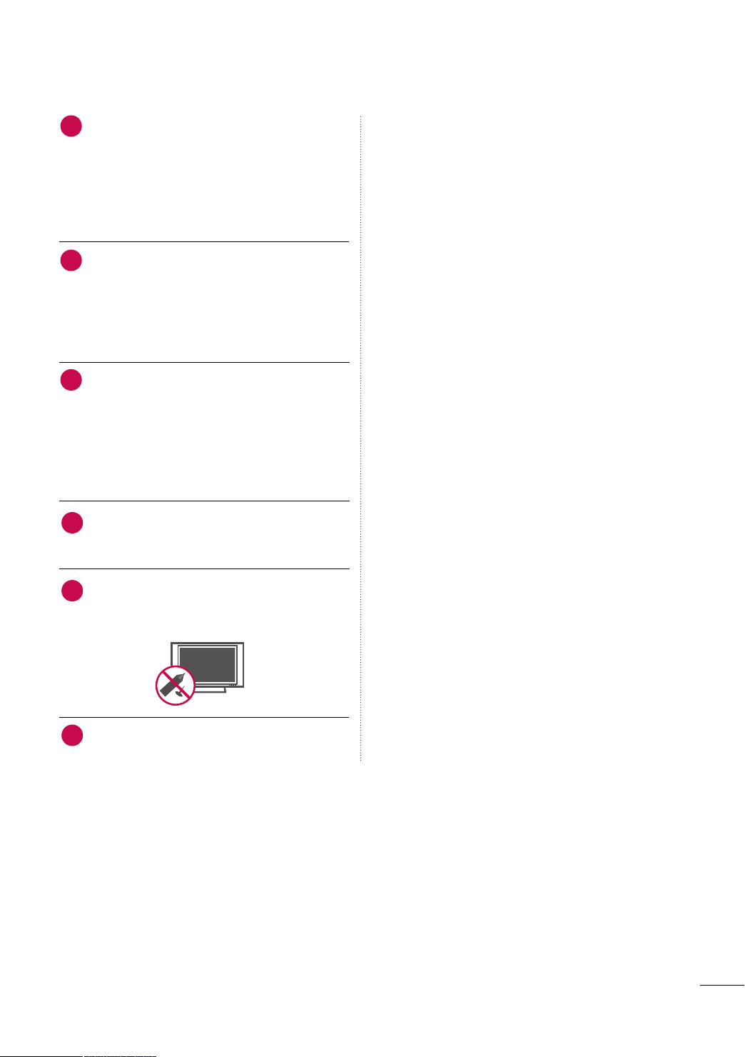
Do not press strongly upon the panel with
24
hand or sharp object such as nail, pencil or
pen, or make a scratch on it.
Keep the product away from direct sunlight.
25
5

CONTENTS
WARNING / CAUTION
SAFETY INSTRUCTIONS
FEATURE OF THIS TV
. . . . . . . . . . . . . . . . . . . . . . . . . . . .
. . . . . . . . . . . . . . . . . . . . . . . . . . 3
. . . . . . . . . . . . . . . . . . . . . . . . . . . . . . . 8
PREPARATION
Accessories
Front Panel Information
Back Panel Information
Stand Instruction
Cable Arrangement
Desktop Pedestal Installation
Swivel Stand . . . . . . . . . . . . . . . . . . . . . . . . . . . . . . . . . . . . . . . . . . . . . . . . . . . . 14
VESA Wall Mounting
Securing the TV to the wall to prevent falling when
the TV is used on a stand
Antenna or Cable Connection
. . . . . . . . . . . . . . . . . . . . . . . . . . . . . . . . . . . . . . . . . . . . . . . . . . . . . . 9
. . . . . . . . . . . . . . . . . . . . . . . . . . . . . . . . . . .10
. . . . . . . . . . . . . . . . . . . . . . . . . . . . . . . . . . . . . 11
. . . . . . . . . . . . . . . . . . . . . . . . . . . . . . . . . . . . . . . . . . . . . 13
. . . . . . . . . . . . . . . . . . . . . . . . . . . . . . . . . . . . . . . . . .14
. . . . . . . . . . . . . . . . . . . . . . . . . . . . 14
. . . . . . . . . . . . . . . . . . . . . . . . . . . . . . . . . . . . . . . .
. . . . . . . . . . . . . . . . . . . . . . . . . . . . . . . . 16
. . . . . . . . . . . . . . . . . . . . . . . . . . 17
15
EXTERNAL EQUIPMENT SETUP
HD Receiver Setup
DVD Setup
VCR Setup
. . . . . . . . . . . . . . . . . . . . . . . . . . . . . . . . . . . . . . . . . . . . . . . . . . . . . . 21
. . . . . . . . . . . . . . . . . . . . . . . . . . . . . . . . . . . . . . . . . . . . . . . . . . . . . 23
Other A/V Source Setup
PC Setup
. . . . . . . . . . . . . . . . . . . . . . . . . . . . . . . . . . . . . . . . . . . . . . . . . . . . . . . .25
. . . . . . . . . . . . . . . . . . . . . . . . . . . . . . . . . . . . . . . . .
. . . . . . . . . . . . . . . . . . . . . . . . . . . . . . . . . 24
USB Connection . . . . . . . . . . . . . . . . . . . . . . . . . . . . . . . . . . . . . . . . . . . . . 30
Variable Out
Monitor Out
. . . . . . . . . . . . . . . . . . . . . . . . . . . . . . . . . . . . . . . . . . . . . . . . . . . . 31
. . . . . . . . . . . . . . . . . . . . . . . . . . . . . . . . . . . . . . . . . . . . . . . . . . . 31
18
2
Channel List
Favorite Channel Setup
. . . . . . . . . . . . . . . . . . . . . . . . . . . . . . . . . . . . . . . . . . . . . . . . . . . . 45
. . . . . . . . . . . . . . . . . . . . . . . . . . . . . . . . . . . . 46
Favorite Channel List . . . . . . . . . . . . . . . . . . . . . . . . . . . . . . . . . . . . . . .47
AV Mode
. . . . . . . . . . . . . . . . . . . . . . . . . . . . . . . . . . . . . . . . . . . . . . . . . . . . . . . .48
Key Lock . . . . . . . . . . . . . . . . . . . . . . . . . . . . . . . . . . . . . . . . . . . . . . . . . . . . . . . . . 49
SIMPLINK
. . . . . . . . . . . . . . . . . . . . . . . . . . . . . . . . . . . . . . . . . . . . . . . . . . . . . . .50
BLUETOOTH
Bluetooth? . . . . . . . . . . . . . . . . . . . . . . . . . . . . . . . . . . . . . . . . . . . . . . . . . . . . . .52
Setting the bluetooth
Set TV PIN
. . . . . . . . . . . . . . . . . . . . . . . . . . . . . . . . . . . . . . . . . . . . . . . . . . . . . 54
Bluetooth headset
Managing Registered Bluetooth device
My Bluetooth Information
Viewing the photos with Bluetooth device
Listening the Musics with Bluetooth device
. . . . . . . . . . . . . . . . . . . . . . . . . . . . . . . . . . . . . . 53
. . . . . . . . . . . . . . . . . . . . . . . . . . . . . . . . . . . . . . . . . . . 55
. . . . . . . . . . . . .57
. . . . . . . . . . . . . . . . . . . . . . . . . . . . . . . .58
. . . . . . . . 59
. . . . . . . 59
USB
Entry Modes
Photo List
Music List
Movie List
DivX Registration Code
Deactivation
. . . . . . . . . . . . . . . . . . . . . . . . . . . . . . . . . . . . . . . . . . . . . . . . . . . 60
. . . . . . . . . . . . . . . . . . . . . . . . . . . . . . . . . . . . . . . . . . . . . . . . . . . . . . .61
. . . . . . . . . . . . . . . . . . . . . . . . . . . . . . . . . . . . . . . . . . . . . . . . . . . . . . .65
. . . . . . . . . . . . . . . . . . . . . . . . . . . . . . . . . . . . . . . . . . . . . . . . . . . . . . .67
. . . . . . . . . . . . . . . . . . . . . . . . . . . . . . . . . . .70
. . . . . . . . . . . . . . . . . . . . . . . . . . . . . . . . . . . . . . . . . . . . . . . . . . . 71
PICTURE CONTROL
WATCHING TV / CHANNEL CONTROL
Remote Control Functions . . . . . . . . . . . . . . . . . . . . . . . . . . . . . . .32
Turning On TV . . . . . . . . . . . . . . . . . . . . . . . . . . . . . . . . . . . . . . . . . . . . . . . .34
Channel Selection
Volume Adjustment
Initializing Setup (Mode Setting)
On-Screen Menus Selection
Quick Menu
Channel Setup
- Auto Scan (Auto Tuning) . . . . . . . . . . . . . . . . . . . . . . . . . . . 40
- Add / Delete Channel (Manual Tuning)
- Channel Editing
Input List
. . . . . . . . . . . . . . . . . . . . . . . . . . . . . . . . . . . . . . . . . . . . . . . . . . . . . . . .43
Input Label
. . . . . . . . . . . . . . . . . . . . . . . . . . . . . . . . . . . . . . . . . . . 35
. . . . . . . . . . . . . . . . . . . . . . . . . . . . . . . . . . . . . . . . .35
. . . . . . . . . . . . . . . . . . . . . . 36
. . . . . . . . . . . . . . . . . . . . . . . . . . . . . 37
. . . . . . . . . . . . . . . . . . . . . . . . . . . . . . . . . . . . . . . . . . . . . . . . . . . . 39
. . . . . .41
. . . . . . . . . . . . . . . . . . . . . . . . . . . . . . . . . . . . . . . . 42
. . . . . . . . . . . . . . . . . . . . . . . . . . . . . . . . . . . . . . . . . . . . . . . . . . . . . 44
Picture Size (Aspect Ratio) Control . . . . . . . . . . . . . . . . . . 72
Preset Picture Settings (Picture Mode)
Manual Picture Adjustment (User Mode)
Picture Improvement Technology
Energy Saving
Power Saving Picture Mode
Picture Reset
. . . . . . . . . . . . . . . . . . . . . . . . . . . . . . . . . . . . . . . . . . . . . . . . .78
. . . . . . . . . . . . . . . . . . . . . . . . . . . . . . 78
. . . . . . . . . . . . . . . . . . . . . . . . . . . . . . . . . . . . . . . . . . . . . . . . . . 79
Image Sticking Minimization (ISM) Method
Demo Mode
Initial Setting (Factory Reset)
. . . . . . . . . . . . . . . . . . . . . . . . . . . . . . . . . . . . . . . . . . . . . . . . . . . . 81
. . . . . . . . . . . . . . . . . . . . . . . . . . .82
. . . . . . . . . . . . .74
. . . . . . . . . . 75
. . . . . . . . . . . . . . . . . . . . . 76
. . . . . .80
6

SOUND & LANGUAGE CONTROL
Auto Volume Leveler (Auto Volume) . . . . . . . . . . . . . . . . . 83
Clear Voice ll
Preset Sound Setting (Sound Mode)
. . . . . . . . . . . . . . . . . . . . . . . . . . . . . . . . . . . . . . . . . . . . . . . . . . . 84
. . . . . . . . . . . . . . . . 85
Sound Setting Adjustment - User Mode
- SRS TruSurround XT
Balance
. . . . . . . . . . . . . . . . . . . . . . . . . . . . . . . . . . . . . . . . . . . . . . . . . . . . . . . . . . 87
TV Speakers On/Off Setup
Selecting Audio Out
Audio Reset
. . . . . . . . . . . . . . . . . . . . . . . . . . . . . . . . . . . . . . . . . . . . . . . . . . . 90
Stereo/SAP Broadcast Setup
On-Screen Menus Language Selection
Closed Captions
. . . . . . . . . . . . . . . . . . . . . . . . . . . . . . . . . 86
. . . . . . . . . . . . . . . . . . . . . . . . . . . . . . 88
. . . . . . . . . . . . . . . . . . . . . . . . . . . . . . . . . . . . . . . . 89
. . . . . . . . . . . . . . . . . . . . . . . . . . .91
. . . . . . . . . . . . .92
. . . . . . . . . . . . . . . . . . . . . . . . . . . . . . . . . . . . . . . . . . . . . 93
TIME SETTING
Clock Setting
- Clock Setup
On/Off Time Setting
Sleep Timer Setting
. . . . . . . . . . . . . . . . . . . . . . . . . . . . . . . . . . . . . . . . . . . . 94
. . . . . . . . . . . . . . . . . . . . . . . . . . . . . . . . . . . . . . 95
. . . . . . . . . . . . . . . . . . . . . . . . . . . . . . . . . . . . . . . . .
96
APPENDIX
Troubleshooting . . . . . . . . . . . . . . . . . . . . . . . . . . . . . . . . . . . . . . . . . . . . . .97
Maintenance . . . . . . . . . . . . . . . . . . . . . . . . . . . . . . . . . . . . . . . . . . . . . . . . . . .99
Product Specifications
IR Codes . . . . . . . . . . . . . . . . . . . . . . . . . . . . . . . . . . . . . . . . . . . . . . . . . . . . .10 2
External Control Through RS-232C
. . . . . . . . . . . . . . . . . . . . . . . . . . . . . . . . . . .10 0
. . . . . . . . . . . . . . . .10 4
7

FEATURE OF THIS TV
■
This feature is not available for all models.
is a trademark of SRS Labs, Inc.
TruSurround XT technology is incorporated under
license from SRS Labs, Inc.
“DivX Certified to play DivX video, including premium
content”
ABOUT DIVX VIDEO: DivX® is a digital video format created by DivX,Inc. This is an official DivX Certified device
that plays DivX video. Visit www.divx.com for more information and software tools to convert your files into DivX
video.
ABOUT DIVX VIDEO-ON-DEMAND: This DivX Certified®
device must be registered in order to play DivX Video-onDemand (VOD) content. To generate the registration code,
locate the DivX VOD section in the device setup menu. Go
to vod.divx.com with this code to complete the registration
process and learn more about DivX VOD.
Manufactured under license from Dolby Laboratories.
“
Dolby
“and the double-D symbol are trademarks of
Dolby Laboratories.
Listen to TV with wireless headset, or enjoy viewing
your mobile phone photos on your TV.
IMPORTANT INFORMATION TO PREVENT “IMAGE BURN
/ BURN-IN” ON YOUR TV SCREEN
■
When a fixed image (e.g. logos, screen menus, video game, and computer display) is displayed on the TV
for an extended period, it can become permanently imprinted on the screen. This phenomenon is known
as “image burn” or “burn-in.” Image burn is not covered under the manufacturer’s warranty.
■
In order to prevent image burn, avoid displaying a fixed image on your TV screen for a prolonged period
(2 or more hours for LCD, 1 or more hours for Plasma).
■
Image burn can also occur on the letterboxed
areas of your TV if you use the 4:3 aspect
ratio setting for an extended period.
8
PREPARATION
1.5V 1.5V
F
A
V
RAT
IO
POW
E
R
Q
.
M
EN
U
MEN
U
A
V
MODE
RETURN
ENTER
VOL
C
H
123
456
78
0
9
Q
.
VIE
W
P
A
G
E
M
U
TE
INPUT
LIST
FREEZE
ENERGY SA
V
ING
SLEEP
MARK
F
A
V
FR
E
E
Z
E
Q
.M
EN
U
MEN
U
LIS
T
123
456
78
0
9
Q
.
VIEW
M
U
TE
VOL
CH
P
A
G
E
R
E
TURN
ENTER
INPUT
POWE
R
A
V
MODE
POWE
R
SA
V
ING
RATIO
T.OPT
TEXT
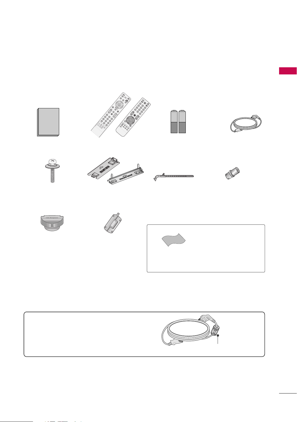
ACCESSORIES
Ensure that the following accessories are included with your TV. If an accessory is missing, please contact the
dealer where you purchased the TV.
The accessories included may differ from the images below.
or
Owner’s Manual Power Cord
Remote Control
or
x 4
Batteries
(Some models)
x 2
PREPARATION
Bolts for stand assembly
(Except 60PS80BR)
Protection Cover
(Refer to P.13)
(Refer to P.13)
Cable Management Clip
(For 50/60PS80BR)
Ferrite core
(For 60PS80BR)
(Refer to P.14 )
For 60PS80BR
Use of ferrite core
Ferrite core can be used to reduce the electromagnetic
wave when connecting the power cord.
The closer the location of the ferrite core to the power
plug, the better it is.
Cable Holder
(Refer to P.14)
Polishing Cloth
(Not included with all models.)
Install the power plug closely.
RF Adapter
(Some models)
You must connect it to the antenna
wire after fixing in Antenna Input.
This adapter is only supplied in
AA rrggee nnttiinnaa
* Wipe spots on the exterior only with
the polishing cloth.
* Do not wipe roughly when removing
stain. Excessive pressure may cause
scratch or discoloration.
.
9
PREPARATION
CH
VOL
MENU
INPUT
ENTER
CH
VOL
MENU
INPUT
ENTER
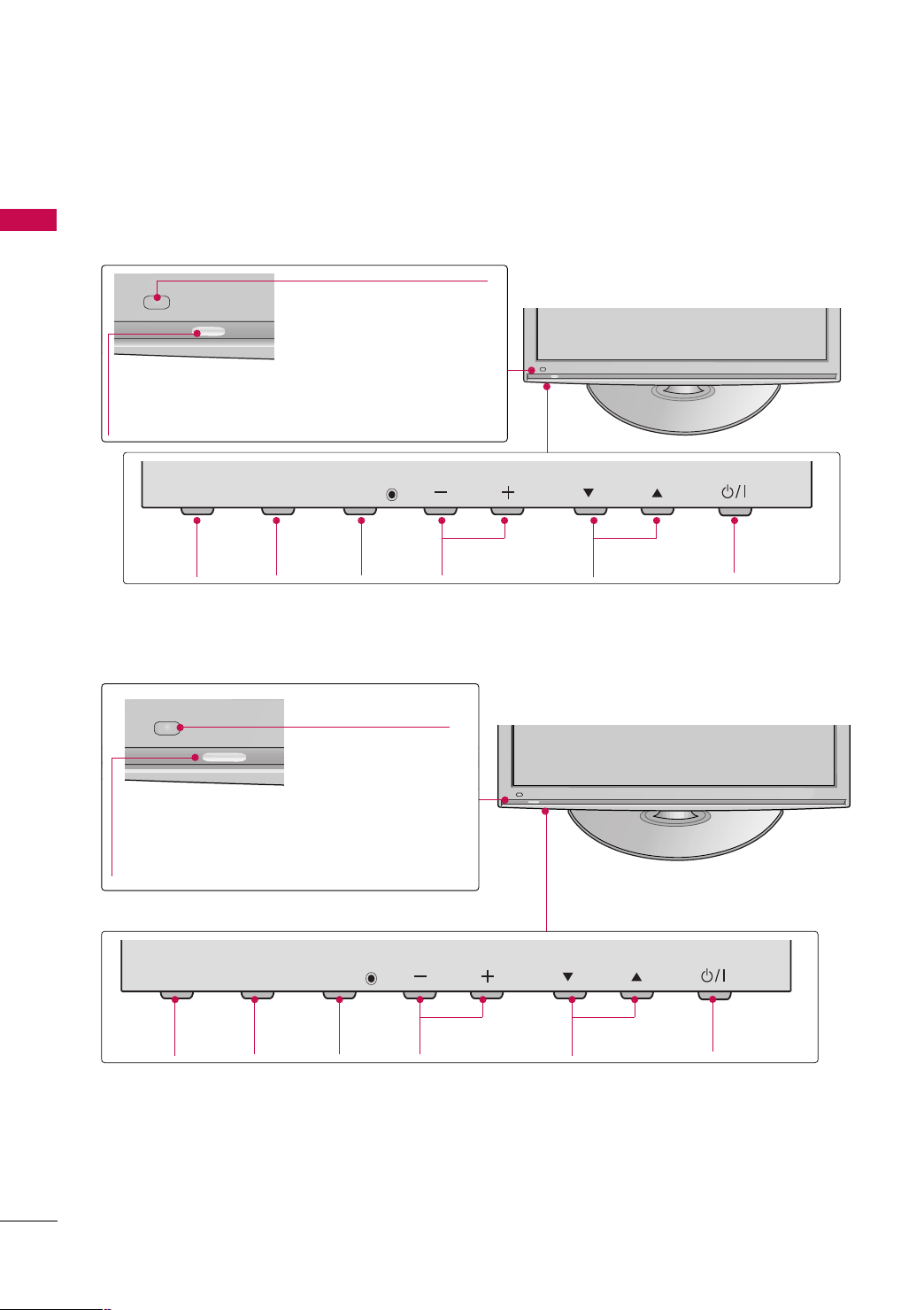
FRONT PANEL INFORMATION
■
Image shown may differ from your TV.
PREPARATION
42/50PQ10R
Remote Control Sensor
Power/Standby Indicator
Illuminates red in standby mode.
Illuminates blue when the TV is switched on.
INPUT
INPUT
Button
MENU
MENU
Button
ENTER
42PQ20R
Intelligent Sensor
Adjusts picture according to
the surrounding conditions.
Remote Control Sensor
Power/Standby Indicator
Illuminates red in standby mode.
Illuminates blue when the TV is switched on.
ENTER
Button
VOL
VOLUME
(-, +) Buttons
CH
CHANNEL
EE,DD
(
)Buttons
POWER
Button
10
INPUT
INPUT
Button
MENU
MENU
Button
ENTER
ENTER
Button
VOL
VOLUME
(-, +) Buttons
CH
CHANNEL
EE,DD
)Buttons
(
POWER
Button
CH
VOL
MENU
INPUT
ENTER
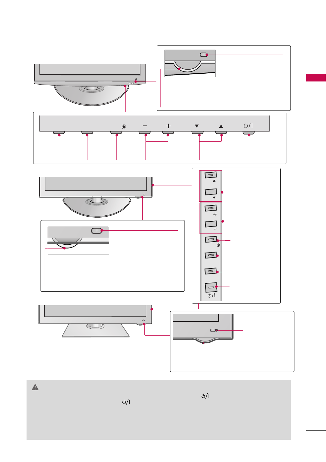
42/50PQ30R
Remote Control Sensor/
Intelligent Sensor
Adjusts picture according to the
surrounding conditions.
PREPARATION
Power/Standby Indicator
Illuminates red in standby mode.
Illuminates blue when the TV is switched on.
INPUT
INPUT
Button
MENU
MENU
Button
ENTER
42/50PQ60R
Power/Standby Indicator
Illuminates red in standby mode.
Illuminates white when the TV is switched on
and goes out slowly.
50/60PS80BR
VOL
ENTER
Button
VOLUME
(-, +) Buttons
Remote Control Sensor/
Intelligent Sensor
Adjusts picture according to the
surrounding conditions.
CH
CHANNEL
EE,DD
)Buttons
(
CH
CH
VOL
VOL
ENTER
MENU
INPUT
POWER
Button
CHANNEL (EE,DD)
Buttons
VOLUME (+, -)
Buttons
ENTER Button
MENU Button
INPUT Button
POWER Button
IInn tt eelllliigg eenntt SSee nnss oorr
Adjusts picture
according to the surrounding conditions.
RReemmoottee CC oonnttrr ooll
Power/Standby Indicator
Illuminates red in standby mode.
The LED is off while the TV remains on.
SS eennss oorr
CAUTION
When the TV cannot be turned on with the remote control, press the (power) button on the TV.(The
GG
remote control will not work when the (power) button is switched off.)
(some models)
Do not step on the glass stand or subject it to any impact. It may break, causing possible injury from frag-
GG
ments of glass, or the TV may fall. (For 50/60PS80BR)
Do not drag the TV. The floor or the product may be damaged. (For 50/60PS80BR)
GG
11
PREPARATION
RS-
232
C IN
(CONTROL & SERVICE)
RGB(PC)
ANTENNA
IN
COMPONENT IN
AUDIO IN
(RGB/DVI)
AV
( )
1
2
VIDEO
Mono
( )
AUDIO
-
-
VARIABLE AUDIO OUT
IN1
OUT
1
2
VIDEO
AUDIO
R
B
IN
/DVI IN
RS-
232
C IN
(CONTROL & SERVICE)
ANTENNA
IN
COMPONENT IN
VIDEO
AUDIO
R
B
IN
USB IN
SERVICE ONLY
IN
VIDEO
MONO
( )
AUDIO
-
-
AV
PREPARATION
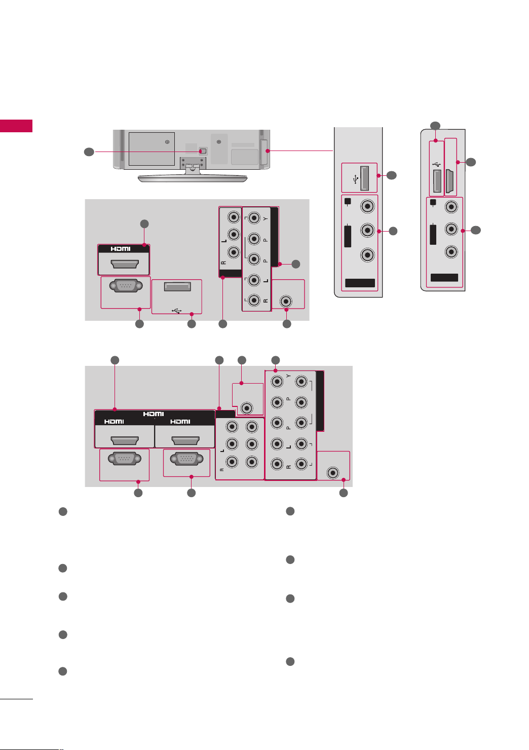
BACK PANEL INFORMATION
■
Image shown may differ from your TV.
9
For 42/50PQ10R
1
6
2 4
For 42PQ20R, 42/50PQ30R, 42/50PQ60R, 50/60PS80BR
1
5
78
64
42PQ20R,
42/50PQ30R
USB IN
R
AUDIO
L/MONO
6
VIDEO
AV IN 2
42/50PQ60R,
50/60PS80BR
8
4
8
USB IN
R
AUDIO
L/MONO
VIDEO
AV IN 2
1
HDMI IN 3
4
12
1
2
HDMI
3
Digital Connection. Supports HD video and Digital
audio.
Accepts DVI video using an adapter or HDMI to
DVI cable (not included)
2
RS-232C IN (CONTROL & SERVICE) PORT
Used by third party devices.
3
RGB (PC)
Analog PC Connection. Uses a D-sub 15 pin cable
(VGA cable).
4
AV (Audio/Video) IN/OUT
Analog composite connection. Supports standard
definition video only (480i).
5
AUDIO IN (RGB/DVI)
1/8”(0.32cm) headphone jack for analog PC audio
input.
7
6
COMPONENT IN
Analog Connection. Supports SD/HD.
Uses a red, green, and blue cable for video & red
and white for audio.
7
ANTENNA IN
Connect over-the air signals to this jack.
Connect cable signals to this jack.
8
USB IN
Used for photo, music and movie.
USB IN SERVICE ONLY
(For
42/50PQ10R)
Used for software updates.
Power Cord Socket
9
For operation with AC power.
Caution: Never attempt to operate the TV on DC
power.
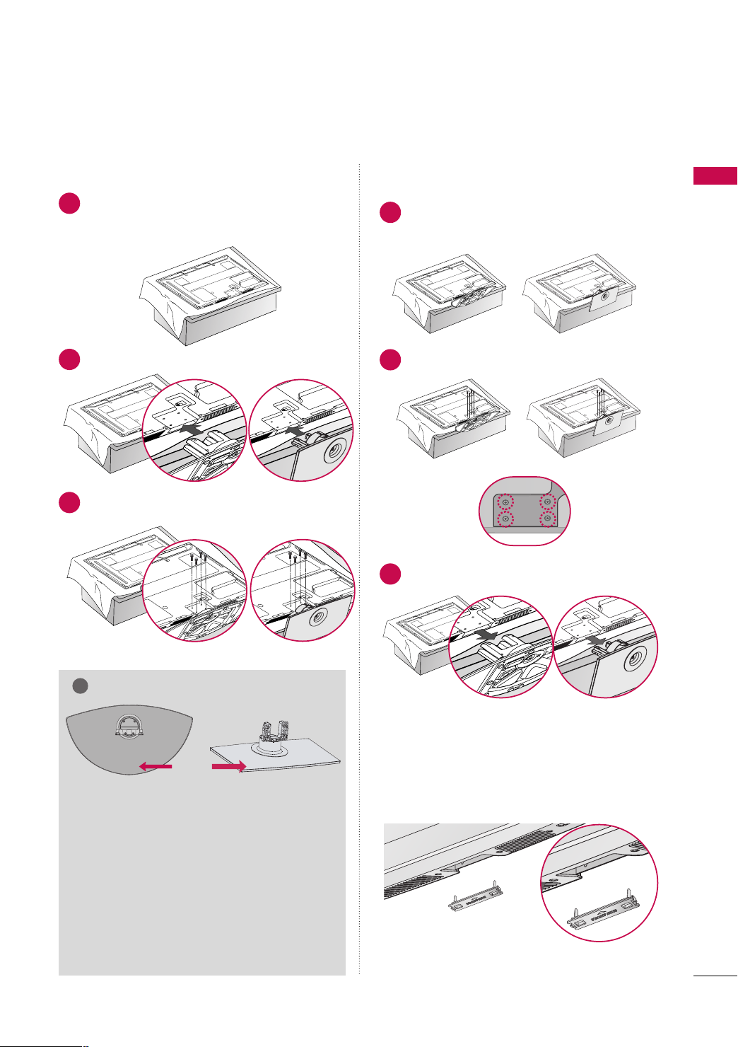
STAND INSTRUCTION
!
■
Image shown may differ from your TV.
Installation Detachment
Carefully place the TV screen side down on a
1
cushioned surface to protect the screen from
damage.
Assemble the TV as shown.
2
Fix the 4 bolts securely using the holes in the
3
back of the TV.
(Except 60PS80)
Carefully place the TV screen side down on a
1
cushioned surface to protect the screen from
damage.
Loose the bolts from TV.
2
Detach the stand from TV.
3
PREPARATION
NOTE
PROTECTION COVER
FRONT
Except
50/60PS80BR
When assembling the stand, make sure to distinguish
GG
and assemble the front and rear side of the stand
correctly.
When assembling the desk type stand, check
GG
whether the bolt is fully tightened. (If not tightened fully, the product can tilt forward after the
product installation). If you tighten the bolt
with excessive force, the bolt can deviate from
abrasion of the tightening part of the bolt.
For
50/60PS80BR
After removing the stand, install the included
pprrootteecc ttiioonn ccoo vvee rr
Press the
until you hear it click.
PPRROOTTEECCTTIIOONN CCOOVVEERR
over the hole for the stand.
into the TV
13
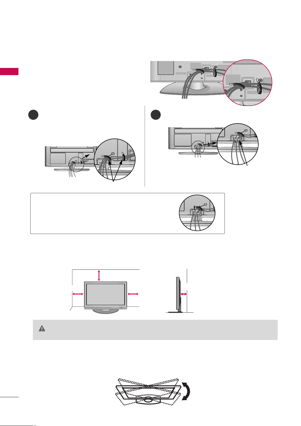
PREPARATION
CABLE ARRANGEMENT
■
Image shown may differ from your TV.
After connecting the cables as necessary, install
PREPARATION
CABLE HOLDER as shown and bundle the cables.
50/60PS80BR
After Connecting the cables as necessary, install
1
CABLE HOLDER as shown and bundle the cables.
To connect additional equipment, see the
EE xx tteerrnnaall eeqquuii ppmmee nntt SSeettuupp
section.
CABLE HOLDER
2
Install the
CCAABBLLEE MMAANNAAGGEEMMEENNTT CCLLIIPP
CABLE MANAGEMENT CLIP
as shown.
How to remove the CABLE MANAGEMENT CLIP
Hold the CABLE MANAGEMENT CLIP with
GG
both hands and pull it upward.
DESKTOP PEDESTAL INSTALLATION
■
Image shown may differ from your TV.
For proper ventilation, allow a clearance of 4 inches on all four sides from the wall.
4 inches
4 inches
CAUTION
4 inches
Ensure adequate ventilation by following the clearance recommendations.
GG
Do not mount near or above any type of heat source.
GG
4 inches
SWIVEL STAND
(This feature is not available for all models.)
After installing the TV, you can adjust the TV manually to the left or right direction by 20 degrees to suit your
viewing position.
14
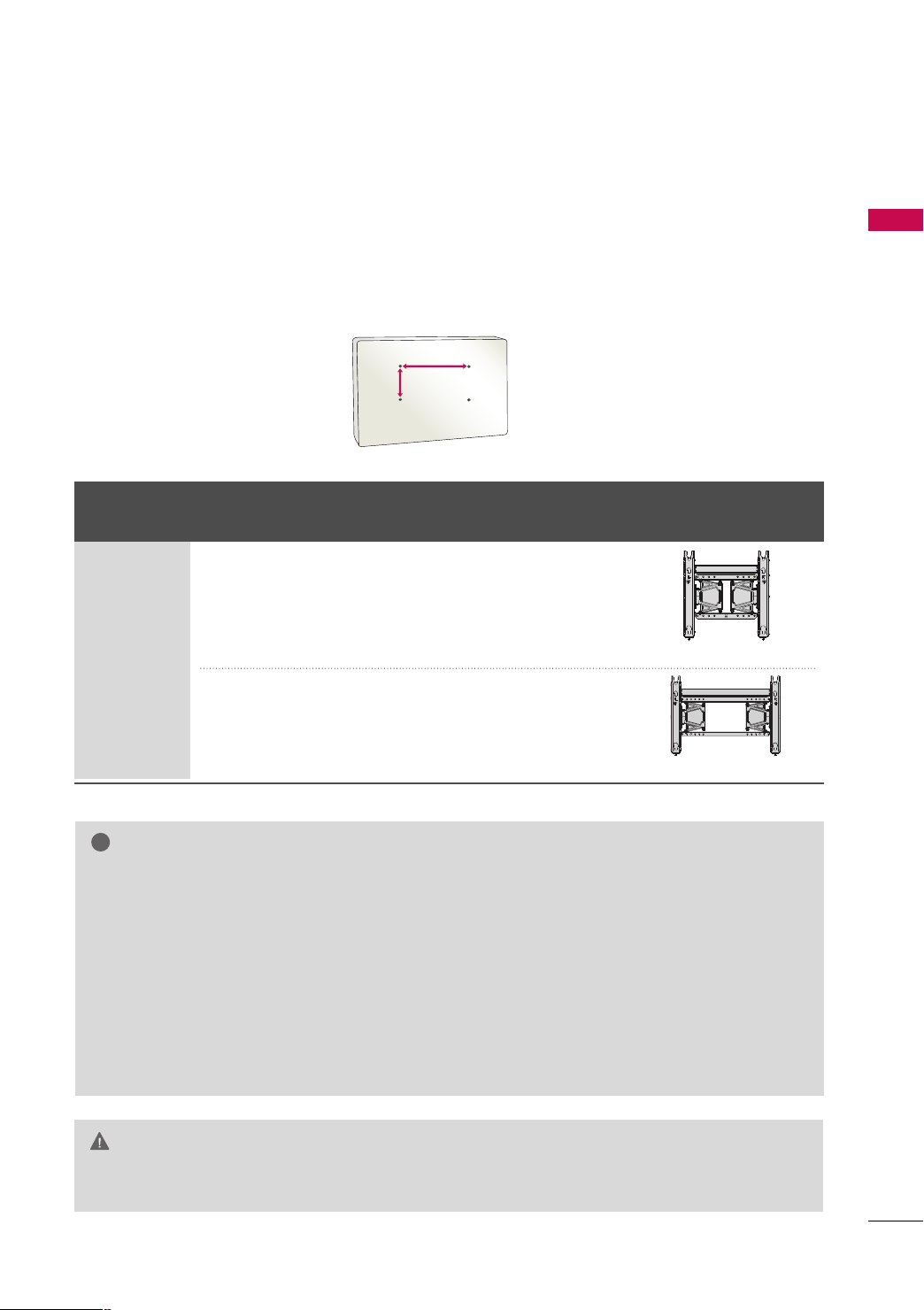
VESA WALL MOUNTING
!
AA
BB
Install your wall mount on a solid wall perpendicular to the floor. When attaching to other building materials, please
contact your nearest installer.
If installed on a ceiling or slanted wall, it may fall and result in severe personal injury.
We recommend that you use an LG brand wall mount when mounting the TV to a wall.
LG recommends that wall mounting be performed by a qualified professional installer.
PREPARATION
Product Models
VESA
(A *B)
42/50PQ10R,
42PQ20R,
42/50PQ30R,
400* 400 M6 4
42/50PQ60R,
50PS80BR
PLASMA TV
60PS80BR
600* 400 M8 4
NOTE
Screw length needed depends on the wall mount
GG
used. For further information, refer to the instructions included with the mount.
Standard dimensions for wall mount kits are shown
GG
in the table.
When purchasing our wall mount kit, a detailed
GG
installation manual and all parts necessary for
assembly are provided.
Do not use screws longer then the standard dimen-
GG
sion, as they may cause damage to the inside to
the TV.
For wall mounts that do not comply with the VESA
GG
Standard Screw Quantity
Wall Mounting Bracket
(sold separately)
(AW-50PG60MS)
(AW-60PG60MS)
standard screw specifications, the length of the
screws may differ depending on their specifications.
Do not use screws that do not comply with the
GG
VESA standard screw specifications.
Do not fasten the screws too strongly. This may
damage the TV or cause the TV to a fall, leading to
personal injury. LG is not liable for these kinds of
accidents.
LG is not liable for TV damage or personal injury
GG
when a non-VESA or non specified wall mount is
used or the consumer fails to follow the TV installation instructions.
CAUTION
Do not install your Wall Mount Bracket while your TV is turned on. It may result in personal injury due to
GG
electric shock.
15
PREPARATION
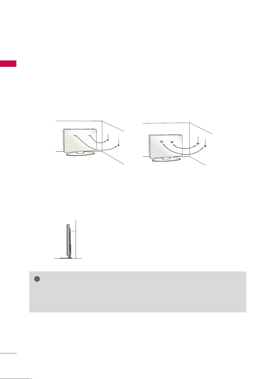
!
SECURING THE TV TO THE WALL TO PREVENT FALLING
WHEN THE TV IS USED ON A STAND
PREPARATION
■
You should purchase necessary components to prevent the TV from tipping over (when not using a wall mount).
■
Image shown may differ from your TV.
We recommend that you set up the TV close to a wall so it cannot fall over if pushed backwards.
Additionally, we recommend that the TV be attached to a wall so it cannot be pulled in a forward direction,
potentially causing injury or damaging the product.
Caution: Please make sure that children don’t climb on or hang from the TV.
■
Insert the eye-bolts (or TV brackets and bolts) to tighten the product to the wall as shown in the picture.
*If your product has the bolts in the eye-bolts position before inserting the eye-bolts, loosen the bolts.
* Insert the eye-bolts or TV brackets/bolts and tighten them securely in the upper holes.
Secure the wall brackets with the bolts (sold separately) to the wall. Match the height of the bracket that is
mounted on the wall to the holes in the product.
Ensure the eye-bolts or brackets are tightened securely.
16
■
Use a sturdy rope (sold separately) to tie the product. It is safer to tie
the rope so it becomes horizontal between the wall and the product.
NOTE
Use a platform or cabinet strong enough and large enough to support the size and weight of the TV.
GG
To use the TV safely, make sure that the height of the bracket on the wall and the one on the TV are
GG
the same.
■
( )
(
)
ANTENNA
IN
( )
(
)
To prevent damage do not connect to the power outlet until all connections are made between the devices.
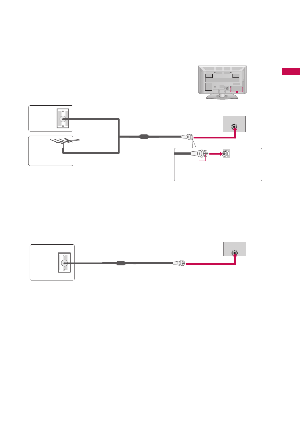
ANTENNA OR CABLE CONNECTION
1. Antenna (Analog)
Wall Antenna Socket or Outdoor Antenna without a Cable Box
Connection.
For optimum picture quality, adjust antenna direction if needed.
Wall
Antenna
Socket
Outdoor
Multi-family Dwellings/Apartments
(Connect to wall antenna socket)
RF Coaxial Wire (75 ohm)
ANTENNA
IN
Antenna
(VHF, UHF)
■
To improve the picture quality in a poor signal area, please purchase a signal amplifier and install properly.
■
If the antenna needs to be split for two TV’s, install a 2-Way Signal Splitter.
■
If the antenna is not installed properly, contact your dealer for assistance.
Single-family Dwellings /Houses
(Connect to wall jack for outdoor antenna)
Copper Wire
Be careful not to bend the copper wire
when connecting the antenna.
2. Cable
PREPARATION
Cable TV
Wall Jack
RF Coaxial Wire (75 ohm)
17
EXTERNAL EQUIPMENT SETUP
IN
IN
Y L RPBP
R
2
RGB(PC)
ANT
AUDIO IN
(RGB/DVI)
AV
VIDEO
VARIABLE AUDIO OUT
IN1
OUT
COMPONENT IN
1
2
VIDEO
AUDIO
R
B
Mono
( )
AUDIO
-
-
IN
IN
■
To prevent the equipment damage, never plug in any power cords until you have finished connecting all equipment.
■
Image shown may differ from your TV.
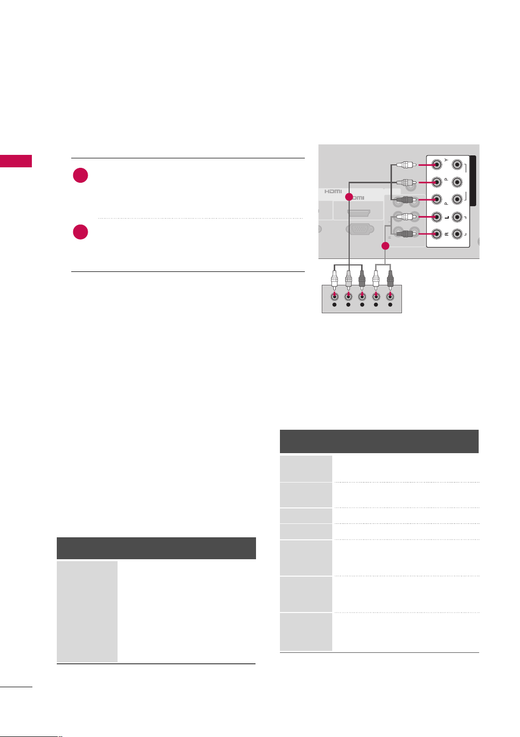
HD RECEIVER SETUP
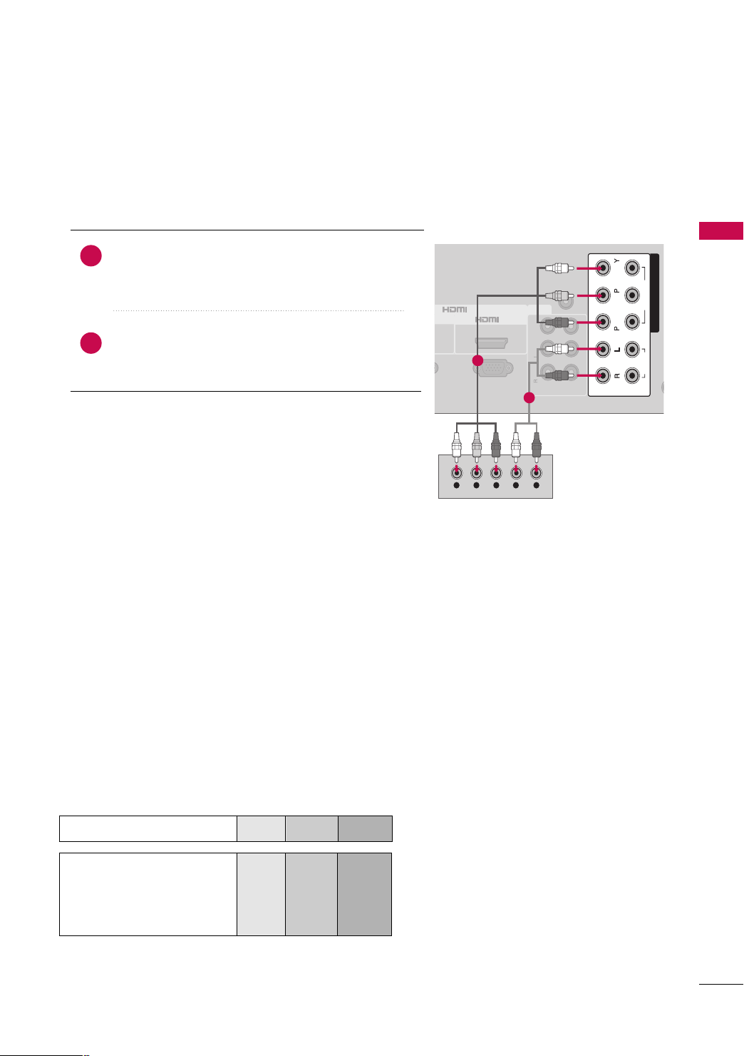
Component Connection
1. How to connect
)
EXTERNAL EQUIPMENT SETUP
Connect the video outputs (Y, P
1
top box to the
CCOOMMPPOONNEENNTT IINN VVIIDDEEOO
PPOONNEENNTT IINN VVIIDDEEOO 11
jack colors (Y = green, P
Connect the audio output of the digital set-top box to
2
CCOOMMPPOONNEENNTT IINN AAUUDDIIOO
the
AAUUDDIIOO 11
CCOOMMPPOONNEENNTT IINN VVIIDDEEOO/AAUUDDIIOO
*
* jacks on the TV.
: For 42/50PQ10R
CCOOMMPPOONNEENNTT IINN VVIIDDEEOO 11/AAUUDDIIOO 11
*
CCOOMMPPOONNEENNTT IINN VVIIDDEEOO 22/AAUUDDIIOO 22
: Except 42/50PQ10R
B, PR
of the digital set-
CCOO MM--
* or
* jacks on the TV. Match the
B = blue, and PR = red).
CCOOMMPPOONNEENNTT IINN
* or
,
1
2
2. How to use
■
Turn on the digital set-top box.
(
Refer to the owner’s manual for the digital set-top box.
)
CCoo mmpp oonneenntt
CCOOMMPPOONNEENNTT IINN 22
CCoo mmpp oonn eenn tt22
: For 42/50PQ10R
Except 42/50PQ10R
Component
Yes
Yes
Yes
Yes
Yes
Yes
Yes
CCoo mmpp oonn eenn tt11
*or
II NN PPUU TT
button
input,
input source on the TV.
HDMI
No
Yes
No
Yes
Yes
Yes
Yes
*
Y, CB/PB, CR/PR
Resolution
720x480i
720x480p
720x576i
720x576p
Horizontal Vertical
Frequency(KHz)Frequency(Hz
15.73 59.94
15.75 60.00
31.47 59.94
31.50 60.00
15.62 50.00
31.25 50.00
)
44.96 59.94
1280x720p
45.00 60.00
37.50 50.00
33.72 59.94
1920x1080i
33.75 60.00
28.12 50.00
56.25 50.00
1920x1080p
67.43 59.94
67.50 60.00
operation
■
Select the
input source on the TV using the
on the remote control.
■
If connected to
select the
(Except 42/50PQ10R)
CCoo mmpp oonneenntt
*
CCoo mmpp oonn eenn tt11::
*
Supported Resolutions
Signal
480i
480p
576i
576p
720 p
10 8 0 i
10 8 0 p
18
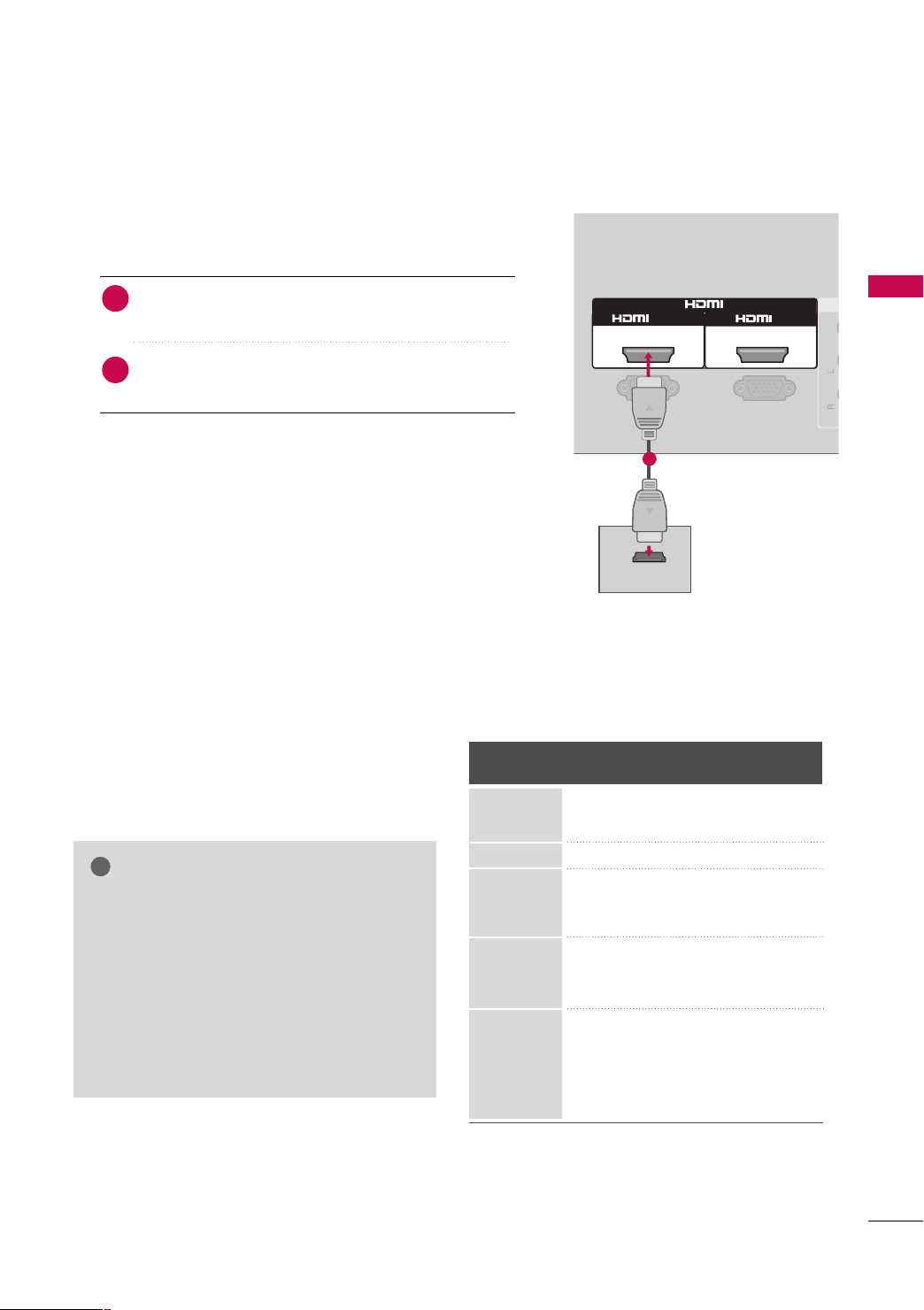
HDMI Connection
RGB(PC)
AV
VIDEO
1
HDMI-DTV OUTPUT
2
RS-232C IN
(CONTROL & SERVICE)
Mono
( )
AUDIO
-
-
IN
/DVI IN
!
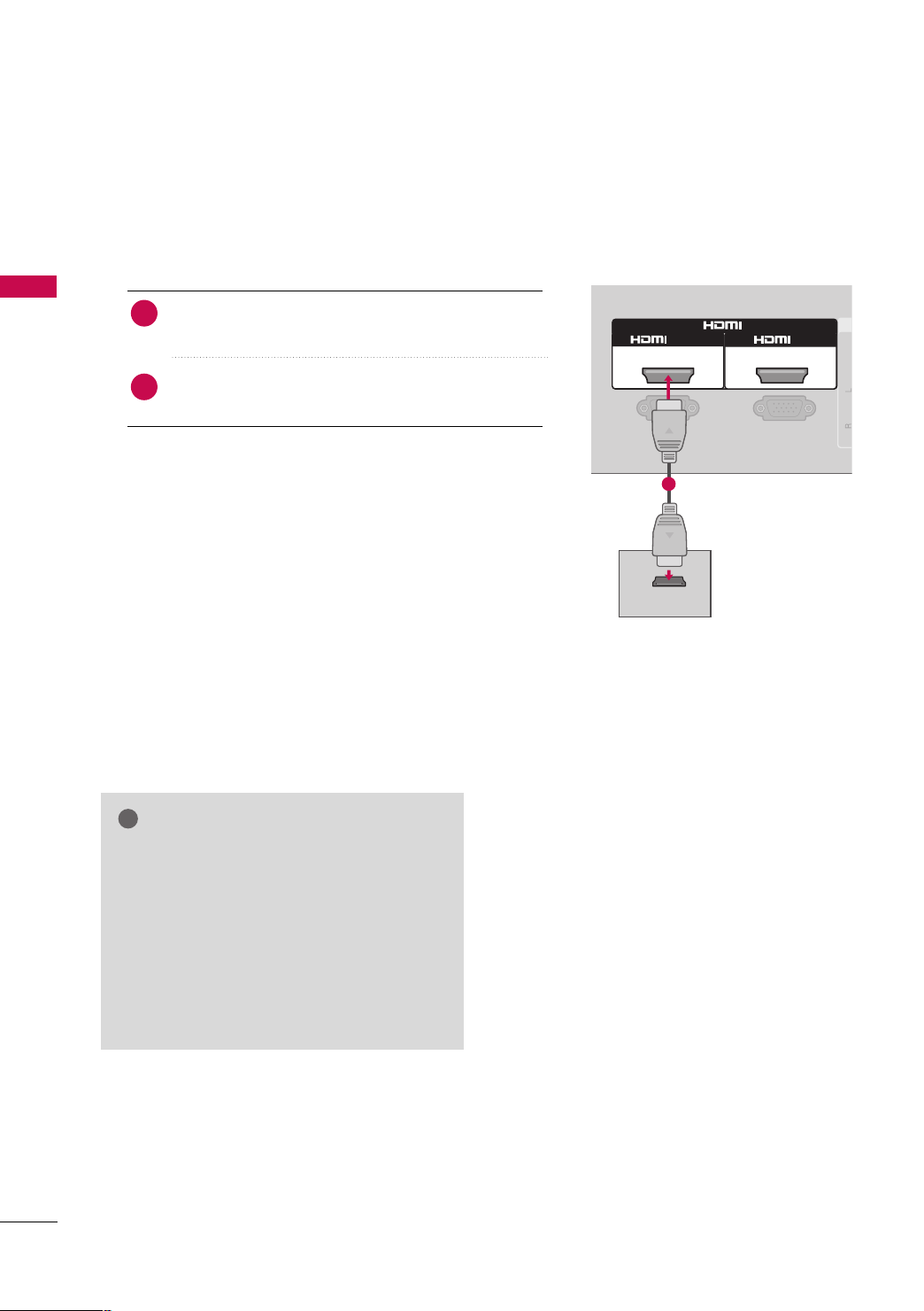
1. How to connect
Connect the digital set-top box to
1
IINN 11
*,
No separate audio connection is necessary.
2
HDMI supports both audio and video.
HHDDMMII IINN
*
HHDDMMII//DD VV II II NN 11, HHDDMMII II NN 22
*
HHDDMMII IINN 33
*
: For 42/50PQ10R
: For 42/50PQ60R, 50/60PS80BR
2. How to use
■
Turn on the digital set-top box.
(
Refer to the owner’s manual for the digital set-top box.
■
Select the
source on the TV using the
control.
HHDDMMII
*
: For 42/50PQ10R
HHDDMMII11,HHDDMMII22
*
HHDDMMII11,HHDDMMII22,HHDDMMII33
*
NOTE
Check HDMI cable over version 1.3.
GG
If the HDMI cables don’t support HDMI version
1.3, it can cause flickers or no screen display. In
this case use the latest cables that support
HDMI version 1.3.
HDMI mode supports PCM audio format only.
GG
If the Audio setting is set to Dolby/DTS/Bitstream
GG
in some DVDP/STB, make sure to change the setting to PCM.
HHDDMMII IINN 22
*or
HHDDMMII IINN 33
: For 42PQ20R, 42/50PQ30R,
42/50PQ60R, 50/60PS80BR
HHDDMMII IINN*,HHDDMMII//DDVVII
HHDDMMII*,HHDDMMII11*,HHDDMMII22
IINNPPUUTT
* or
button on the remote
: For 42PQ20R, 42/50PQ30R,
42/50PQ60R, 50/60PS80BR
: For 42/50PQ60R,
50/60PS80BR
* jack on the TV.
HHDDMMII33
* input
)
HDMI-DTV
Resolution
720x480p
720x576p
1280x720p
1920x1080i
1920x1080p
1
Horizontal Vertical
Frequency(KHz)Frequency(Hz
31.47 59.94
31.50 60.00
31.25 50.00
44.96 59.94
45.00 60.00
37.50 50.00
33.72 59.94
33.75 60.00
28.12 50.00
67.43 59.94
67.50 60.00
56.25 50.00
27.00 24.00
33.75 30.00
EXTERNAL EQUIPMENT SETUP
)
19
EXTERNAL EQUIPMENT SETUP
L R
DVI-DTV OUTPUT
RGB(PC)
AV
VIDEO
IN1
1
AUDIO IN
(RGB/DVI)
2
OUT
RS-232C IN
(CONTROL & SERVICE)
Mono
( )
AUDIO
-
-
VARIABLE AUDIO OUT
IN
/DVI IN
!
EXTERNAL EQUIPMENT SETUP
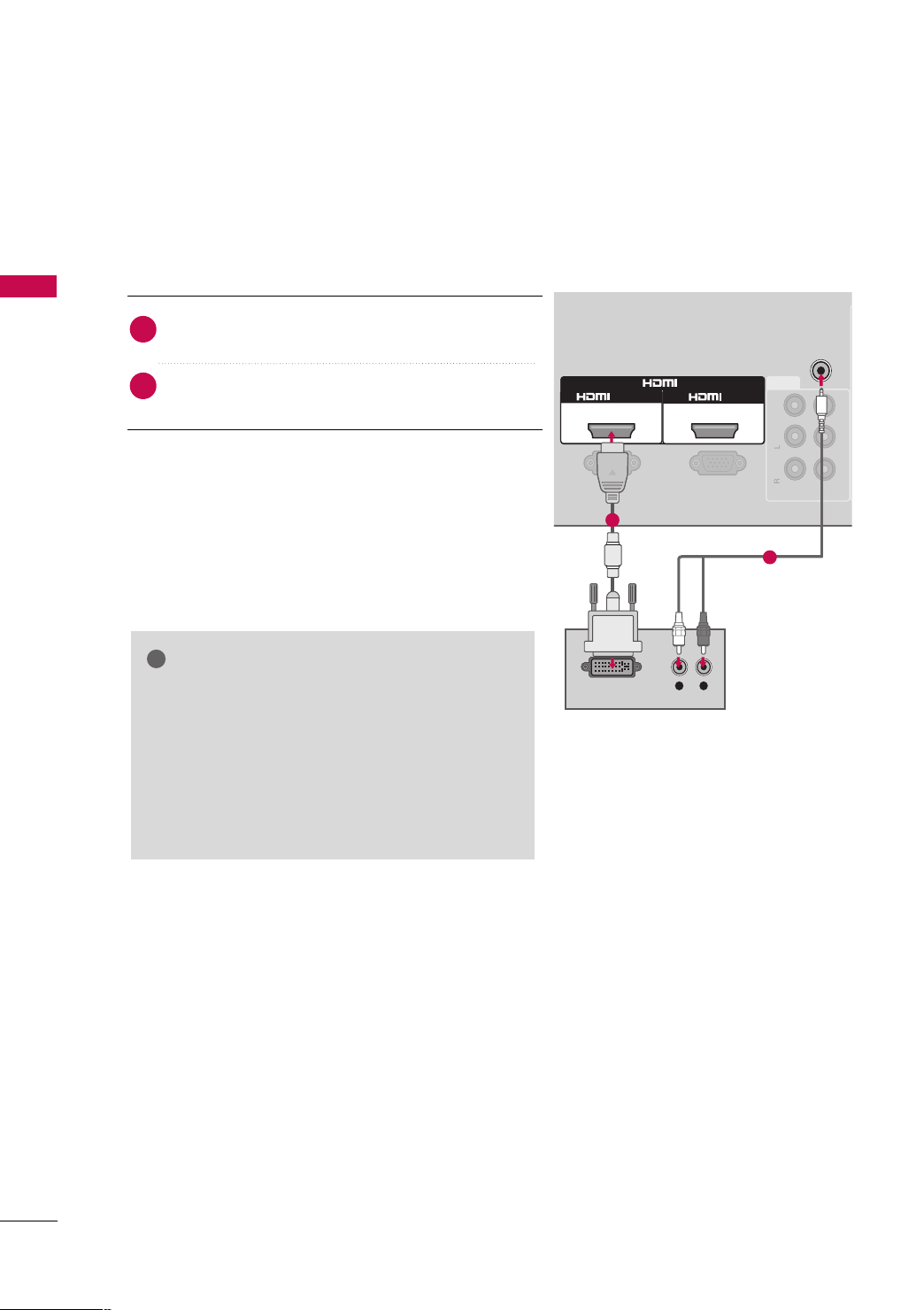
DVI to HDMI Connection
(Except 42/50PQ10R)
1. How to connect
Connect the DVI output of the digital set-top box to
1
2
HHDDMMII//DDVVII IINN 11
the
jack on the TV.
Connect the audio output of the digital set-top box to
AAUUDDIIOO II NN ((RRGGBB//DDVVII))
the
jack on the TV.
2. How to use
■
Turn on the digital set-top box. (Refer to the owner’s manual for the digital set-top box.
■
Select the
II NNPPUUTT
HHDDMMII11
input source on the TV using the
button on the remote control.
NOTE
A DVI to HDMI cable or adapter is required for this
GG
connection. DVI doesn't support audio, so a separate
audio connection is necessary.
HDMI mode supports PCM audio format only.
GG
If the Audio setting is set to Dolby/DTS/Bitstream in
GG
some DVDP/STB, make sure to change the setting to
PCM.
)
1
2
20
DVD SETUP
IN
IN
Y L RPBP
R
2
RGB(PC)
ANT
AUDIO IN
(RGB/DVI)
AV
VIDEO
VARIABLE AUDIO OUT
IN1
OUT
COMPONENT IN
1
2
VIDEO
AUDIO
R
B
Mono
( )
AUDIO
-
-
IN
IN
Component Connection
1. How to connect
)
Connect the video outputs (Y, P B, PR
1
CCOOMMPPOONNEENNTT IINN VVIIDDEEOO
VVIIDDEEOO 11
* jacks on the TV.
Match the jack colors (Y = green, P
Connect the audio outputs of the DVD to the
2
CCOOMMPPOONNEENNTT IINN AAUUDDIIOO
11
* jacks on the TV.
CCOOMMPPOONNEENNTT IINN VVIIDDEEOO/AAUUDDIIOO
*
* or
CCOOMMPPOONNEENNTT IINN AAUUDDIIOO
* or
of the DVD to the
CCOOMMPPOONNEENNTT II NN
B = blue, and PR = red
: For 42/50PQ10R
CCOOMMPPOONNEENNTT IINN VVIIDDEEOO 11/AAUUDDIIOO 11
*
,
CCOOMMPPOONNEENNTT IINN VVIIDDEEOO 22/AAUUDDIIOO 22
: Except 42/50PQ10R
2. How to use
■
Turn on the DVD player, insert a DVD.
■
Select the
the TV using the
■
If connected to
CCoo mmpp oonn eenn tt22
■
Refer to the DVD player's manual for operating instructions.
CCoo mmpp oonneenntt
II NN PPUU TT
CCOOMMPPOONNEENNTT IINN 22
CCoo mmpp oonn eenn tt11
*or
* input source on
button on the remote control.
input, select the
input source on the TV. (Except 42/50PQ10R)
EXTERNAL EQUIPMENT SETUP
)
.
1
2
CCoo mmpp oonneenntt
*
CCoo mmpp oonn eenn tt11::
*
: For 42/50PQ10R
Except 42/50PQ10R
Component Input ports
To get better picture quality, connect a DVD player to the component input ports as shown below.
Component ports on the TV
Video output ports
on DVD player
YPB PR
Y
Y
Y
Y
B-Y
Cb
Pb
B
P
P
R-Y
Cr
Pr
R
21
EXTERNAL EQUIPMENT SETUP
RGB(PC)
A
VIDEO
1
2
RS-232C IN
(CONTROL & SERVICE)
Mono
( )
AUDIO
-
-
HDMI-DVD OUTPUT
IN
/DVI IN
!
HDMI Connection
1. How to connect
EXTERNAL EQUIPMENT SETUP
Connect the HDMI output of the DVD to the
1
HHDDMMII//DDVVII IINN 11
HHDDMMII IINN 22
*,
*or
HHDDMMII IINN 33
on the TV.
No separate audio connection is necessary.
2
HDMI supports both audio and video.
HHDDMMII IINN
*
HHDDMMII//DD VV II II NN 11, HHDDMMII II NN 22
*
: For 42/50PQ10R
: For 42PQ20R, 42/50PQ30R,
42/50PQ60R, 50/60PS80BR
HHDDMMII IINN 33
*
: For 42/50PQ60R, 50/60PS80BR
2. How to use
■
Select the
source on the TV using the
control.
■
Refer to the DVD player's manual for operating instructions.
HHDDMMII
*
: For 42/50PQ10R
HHDDMMII11,HHDDMMII22
*
HHDDMMII11,HHDDMMII22,HHDDMMII33
*
HHDDMMII*,HHDDMMII11*,HHDDMMII22
* or
IINNPPUUTT
button on the remote
: For 42PQ20R, 42/50PQ30R,
42/50PQ60R, 50/60PS80BR
: For 42/50PQ60R,
50/60PS80BR
HHDDMMII33
HHDDMMII IINN
* jack
* input
*,
1
22
NOTE
Check HDMI cable over version 1.3.
GG
If the HDMI cables don’t support HDMI version
1.3, it can cause flickers or no screen display. In
this case use the latest cables that support
HDMI version 1.3.
HDMI mode supports PCM audio format only.
GG
If the Audio setting is set to Dolby/DTS/Bitstream
GG
in some DVDP/STB, make sure to change the setting to PCM.
VCR SETUP
2
AUDIO
ANTENNA
IN
L R
S-VIDEO VIDEO
OUTPUT
SWITCH
ANT IN
ANT OUT
( )
!
ANTEN
IN
COMPONENT IN
1
2
VIDEO
AUDIO
AUDIO IN
(RGB/DVI)
AV
VIDEO
IN1
L R
S-VIDEO VIDEO
OUTPUT
SWITCH
ANT IN
ANT OUT
R
B
Mono
( )
AUDIO
-
-
VARIABLE AUDIO OUT
OUT
( )
IN
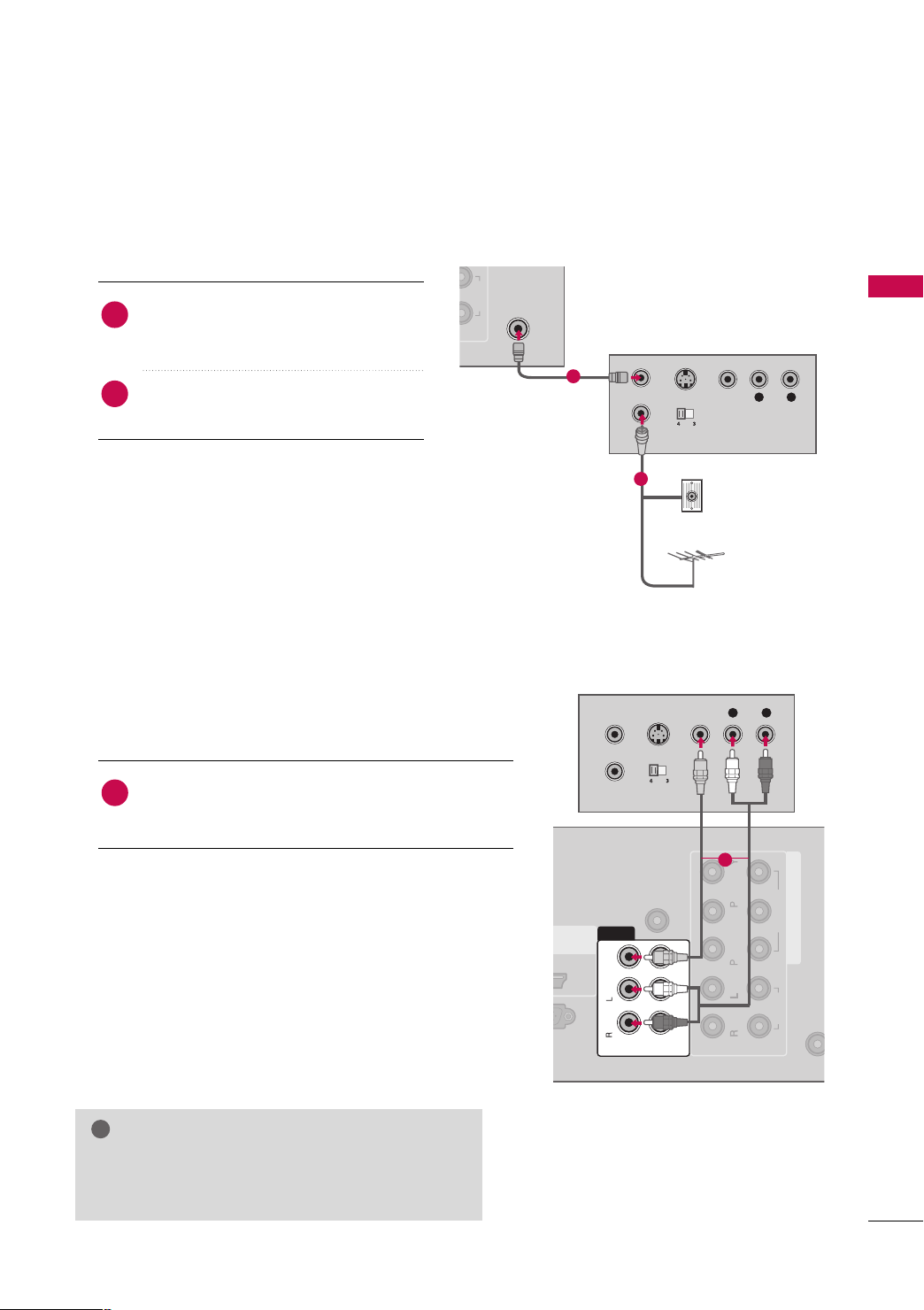
Antenna Connection
1. How to connect
Connect the RF antenna out socket of the
1
VCR to the
AANNTTEENNNNAA II NN
socket on the
TV.
Connect the antenna cable to the RF
2
antenna in socket of the VCR.
2. How to use
■
Set VCR output switch to 3 or 4 and then
tune TV to the same channel number.
■
Insert a video tape into the VCR and press
PLAY on the VCR. (Refer to the VCR owner’s
)
manual.
Composite (RCA) Connection
1. How to connect
Connect the
1
VCR. Match the jack colors (Video = yellow, Audio Left
= white, and Audio Right = red)
AAUUDDIIOO/VVIIDDEEOO
jacks between TV and
EXTERNAL EQUIPMENT SETUP
1
Wall Jack
2
Antenna
2. How to use
■
Insert a video tape into the VCR and press PLAY on the
VCR. (Refer to the VCR owner’s manual.
■
Select the
II NN PPUU TT
■
If connected to
(Except 42/50PQ10R)
AAVV
*
: For 42/50PQ10R
AAVV11::
*
NOTE
If you have a mono VCR, connect the audio cable
GG
from the VCR to the
TV.
AAVV
AAVV11
* or
* input source on the TV using the
button on the remote control.
AAVV IINN 22
Except 42/50PQ10R
AAUUDD IIOO--LL((MMoonnoo))
, select
AAVV22
input source on the TV.
1
)
jack of the
23
EXTERNAL EQUIPMENT SETUP
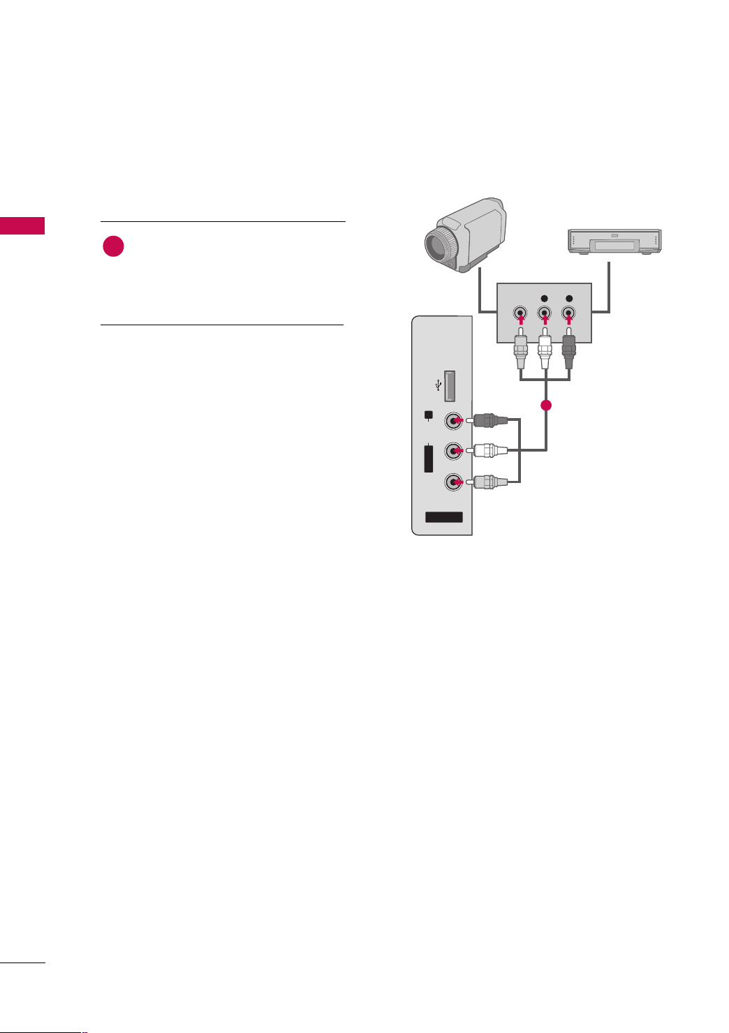
OTHER A/V SOURCE SETUP
■
Image shown may differ from your TV.
1. How to connect
EXTERNAL EQUIPMENT SETUP
Connect the
1
between TV and external equipment.
Match the jack colors
(
Video = yellow, Audio Left = white, and
Audio Right = red
2. How to use
AAUUDDIIOO/VVIIDDEEOO
.
)
jacks
Camcorder
VIDEO
Video Game Set
L R
■
Select the
the
II NN PPUU TT
AAVV22
input source on the TV using
button on the remote control.
(Except 42/50PQ10R)
■
If connected to
select the
■
Operate the corresponding external equipment.
AAVV IINN
*
*
*
*
: For 42/50PQ10R
AAVV IINN 11
AAVV
AAVV11
: Except 42/50PQ10R
: For 42/50PQ10R
: Except 42/50PQ10R
AAVV
* or
AAVV II NN
AAVV11
AAVV IINN 11
* or
* input source on the TV.
* input,
USB IN
R
AUDIO
L/ MONO
VIDEO
AV IN 2
1
24
PC SETUP
RGB OUTPUT
AUDIO
2
1
2
VIDEO
AUDIO
AV
VIDEO
IN1
RGB(PC)
AUDIO IN
(RGB/DVI)
Mono
( )
AUDIO
-
-
VARIABLE AUDIO OUT
R
B
OUT
IN
!
(Except 42/50PQ10R)
This TV provides Plug and Play capability, meaning that the PC adjusts automatically to the TV's settings.
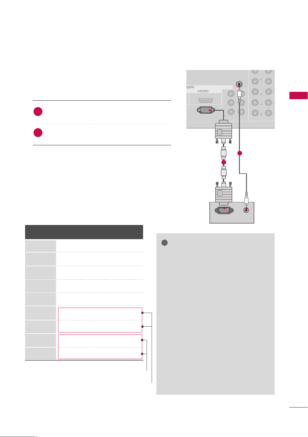
VGA (D-Sub 15 pin) Connection
1. How to connect
Connect the VGA output of the PC to the
1
jack on the TV.
RRGGBB((PP CC
))
EXTERNAL EQUIPMENT SETUP
Connect the PC audio output to the
2
((
RRGGBB// DD VV II
))
jack on the TV.
2. How to use
■
Turn on the TV and the PC.
■
Select the
RRGGBB
input source on the TV using the
button on the remote control.
Supported Display Specifications
(RGB-PC)
Horizontal Vertical
Frequency(KHz)Frequency(Hz
31.468 70.09
31.469 70.09
31.469 59.94
37.879 60.31
48.363 60.00
47.776 59.87
47.720 59.799
63.668 59.895
66.587 59.934
* For FHD models
* Except 42PQ20R, 42PQ30R/60R
Resolution
640x350
720x400
640x480
800x600
1024x768
1280x768
1360x768
1280x1024
1920x1080
AAUUDDIIOO IINN
II NN PPUU TT
)
2
1
NOTES
To get the the best picture quality, adjust the
GG
PC graphics card to 1024x768(42PQ20R,
42PQ30R/60R), 1360x768(50PQ30R/60R),
1920x1080(50/60PS80BR).
In PC mode, there may be noise associated
GG
with the resolution, vertical pattern, contrast
or brightness. If noise is present, change the
PC output to another resolution, change the
refresh rate to another rate or adjust the
brightness and contrast on the PICTURE menu
until the picture is clear.
Avoid keeping a fixed image on the screen for a
GG
long period of time. The fixed image could
become permanently imprinted on the screen.
The synchronization input form for Horizontal
GG
and Vertical frequencies is separate.
Depending on the graphics card, some resolu-
GG
tion settings may not allow the image to be
positioned on the screen properly.
25
EXTERNAL EQUIPMENT SETUP
MENU
ENTER
ENTER
ENTER
ENTER
EXTERNAL EQUIPMENT SETUP
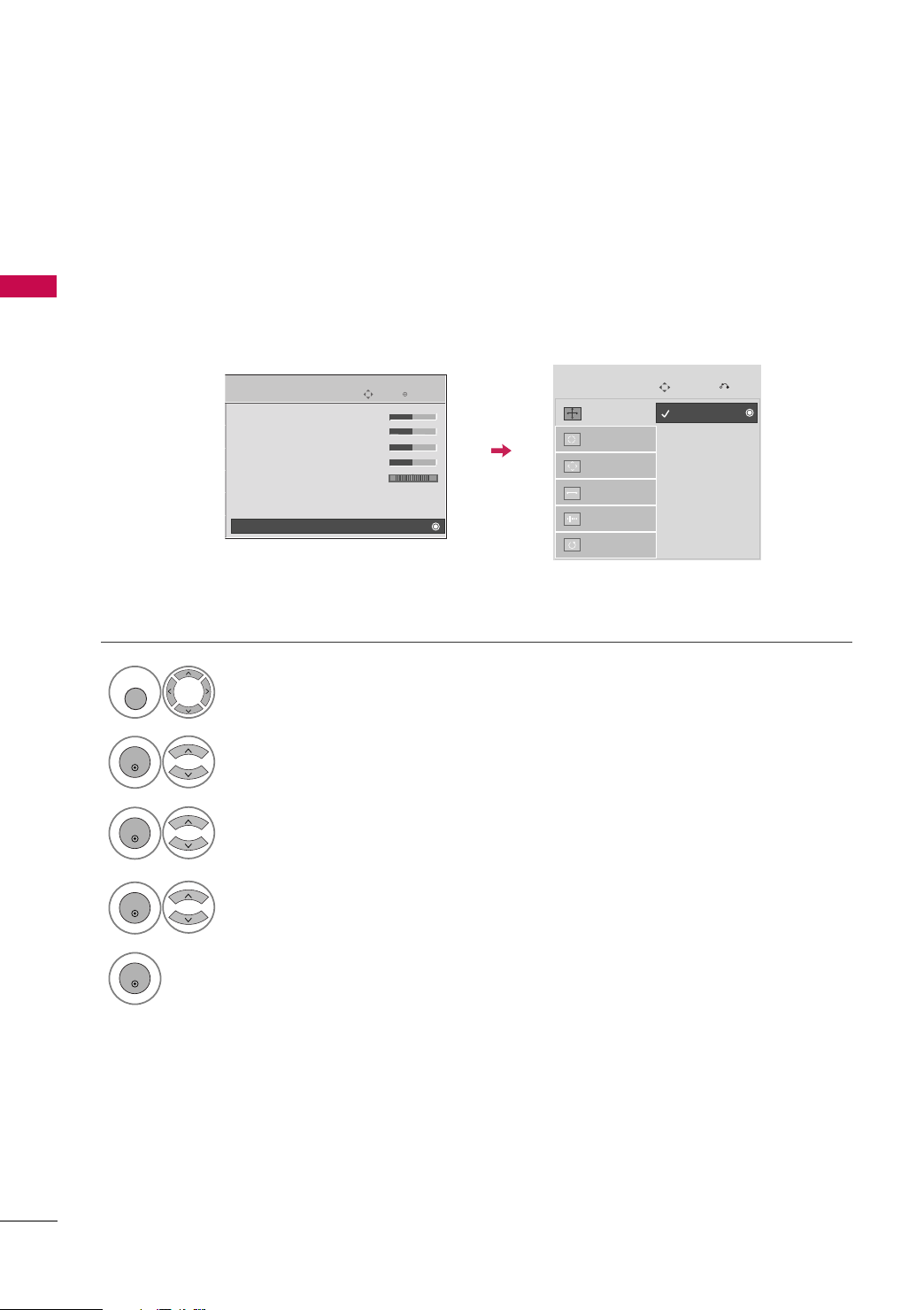
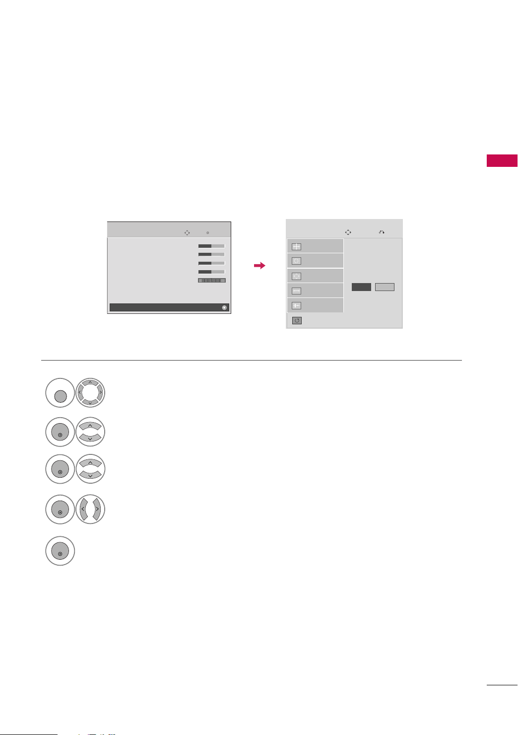
Screen Setup for PC mode
Selecting Resolution
(For 50PQ30R/60R
(Except 42/50PQ10R)
You can choose the resolution in RGB mode.
PPoossiittiioonn, PPhhaassee
The
PICTURE
Screen
, and
SSiizzee
can also be adjusted.
E
• Contrast 70
• Brightness 40
• Sharpness 70
• Color 70
• Tint 0
• Advanced Control
• Picture Reset
Move
1
PPIICCTT UURR EE
Select
.
, 50/60PS80BR
Enter
RG
)
Screen
Resolution
Auto config.
Position
Size
Phase
Reset
G
Move
1024 x 768
1280 x 768
1360 x 768
Prev.
26
2
3
4
5
SSccrreeee nn
Select
Select
.
RReessoolluutt iioonn
.
Select the desired resolution.
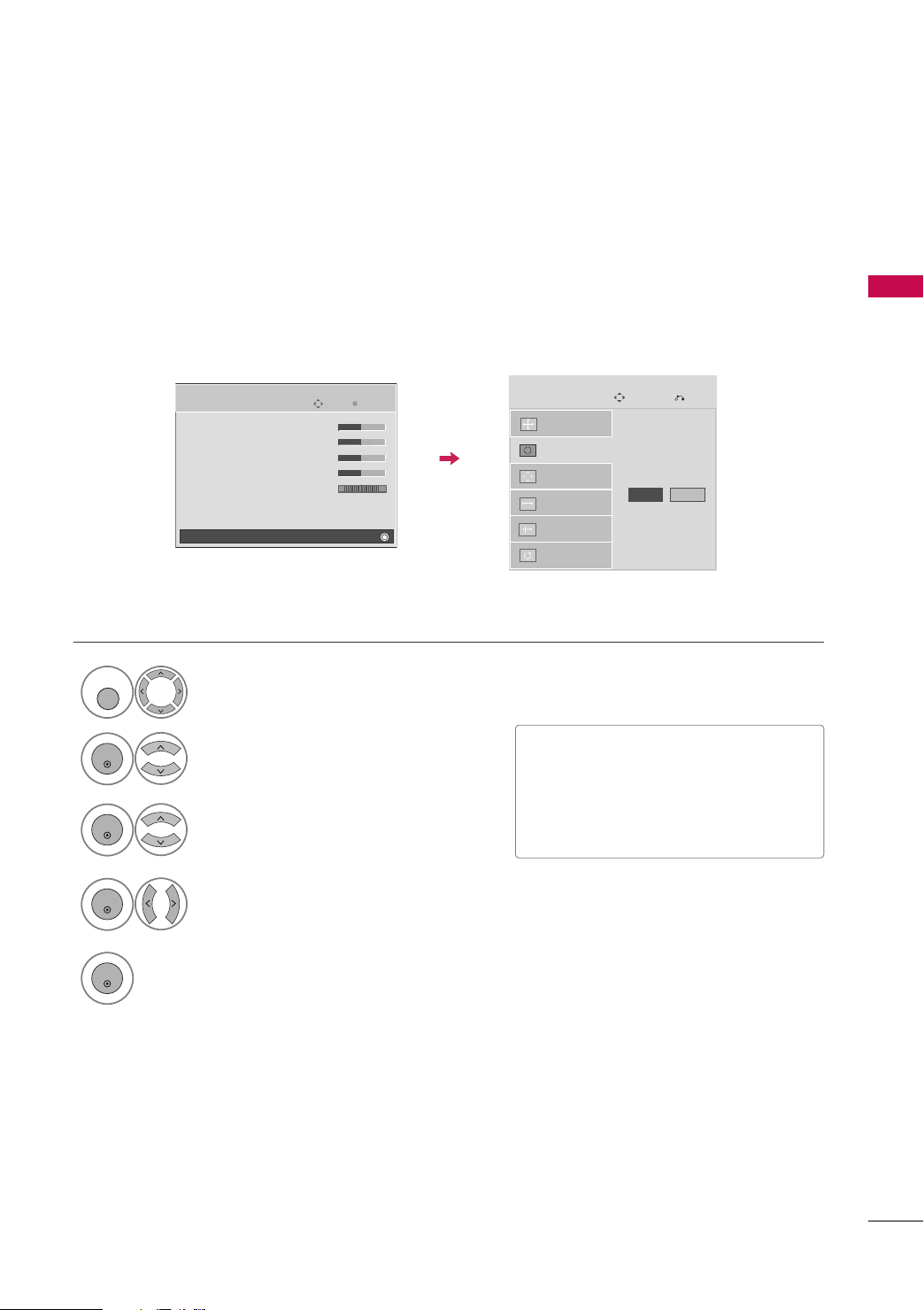
Auto Configure
ENTER
ENTER
ENTER
ENTER
MENU
Automatically adjusts picture position and minimizes image instability. After adjustment, if the image is still
not correct, try using the manual settings or a different resolution or refresh rate on the PC.
EXTERNAL EQUIPMENT SETUP
1
2
3
4
PICTURE
Screen
Select
Select
Select
Select
E
• Contrast 70
• Brightness 40
• Sharpness 70
• Color 70
• Tint 0
• Advanced Control
• Picture Reset
PPIICCTT UURR EE
SSccrreeee nn
.
.
AAuu ttoo ccoo nnffiigg..
YYeess
.
Move
Enter
RG
.
Screen
Resolution
Auto config.
Position
Size
Phase
Reset
Move
G
Prev.
To Set
Yes No
• If the position of the image is still not
correct, try Auto adjustment again.
• If picture needs to be adjusted again
after Auto adjustment in RGB, you can
adjust the
PPoossiittiioo nn, SS iizz ee
or
PP hhaassee
.
5
Start Auto Configuration.
27
EXTERNAL EQUIPMENT SETUP
ENTER
ENTER
MENU
ENTER
ENTER
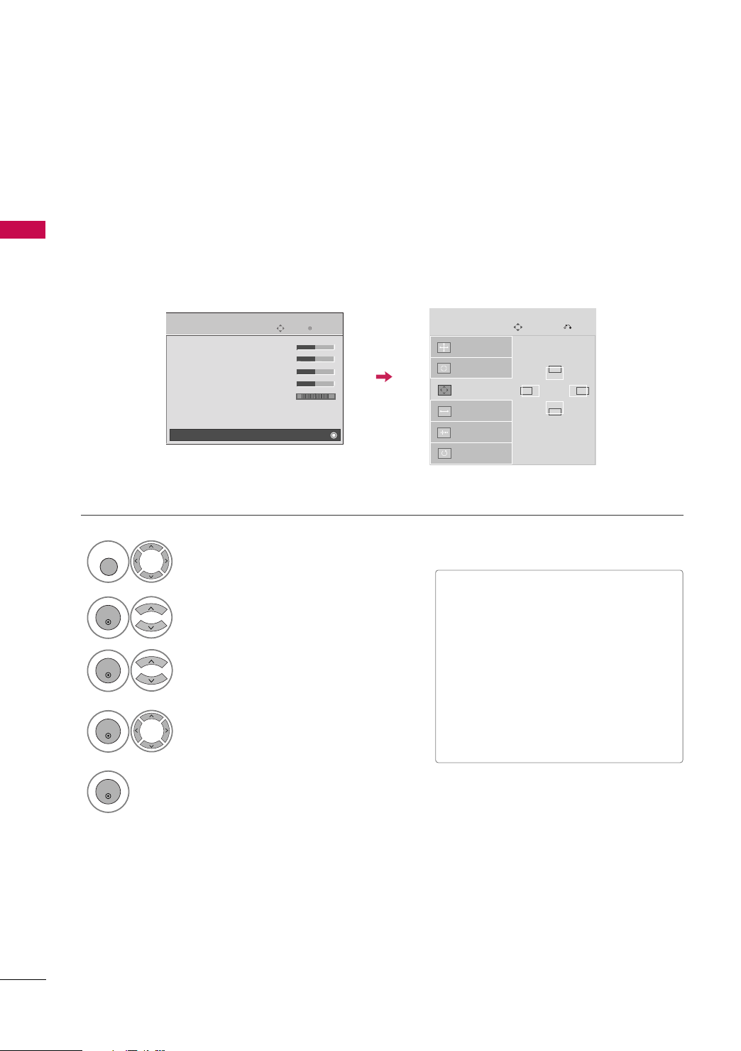
Adjustment for screen Position, Size, and Phase
If the picture is not clear after auto adjustment and especially if characters are still trembling, adjust the picture
phase manually.
EXTERNAL EQUIPMENT SETUP
Position: This feature operates only in Component(except 480i, 576i) and RGB mode.
Size, Phase: This feature operates only in RGB mode.
1
2
3
4
PICTURE
Screen
Select
Select
Select
• Contrast 70
• Brightness 40
• Sharpness 70
• Color 70
• Tint 0
• Advanced Control
• Picture Reset
PPIICCTT UURR EE
SSccrreeee nn
PPoossiittiioo nn, SS iizz ee
E
.
Move
RG
.
Make appropriate adjustments.
, or
Enter
PP hhaassee
Screen
Resolution
Auto config.
Position
Size
Phase
Reset
■
PPoossiittiioo nn
Move
G
: This function is to adjust pic-
Prev.
D
GF
E
ture to left/right and up/down as you
prefer.
■
SS iizz ee
: This function is to minimize any
.
vertical bars or stripes visible on the
screen background. And the horizontal
screen size will also change.
■
PP hh aa ss ee
: This function allows you to
remove any horizontal noise and clear or
sharpen the image of characters.
5
28
Screen Reset (Reset to original factory values)
ENTER
MENU
ENTER
ENTER
ENTER
Returns
PPoo ss iitt iioonn, SSii zz ee
, and
PPhhaass ee
to the default factory settings.
This feature operates only in Component(except 480i, 576i) and RGB mode.
PICTURE
• Contrast 70
• Brightness 40
• Sharpness 70
• Color 70
• Tint 0
• Advanced Control
• Picture Reset
Screen
Move
E
Enter
RG
Screen
Resolution
Auto config.
Position
Size
Phase
Reset
1
PPIICCTT UURR EE
Select
.
2
SSccrreeee nn
Select
.
G
Move
To Set
Yes No
EXTERNAL EQUIPMENT SETUP
Prev.
3
4
5
Select
Select
RReessee tt
YYeess
.
.
29
EXTERNAL EQUIPMENT SETUP
USB IN
AV IN 2
L/MONO
R
AUDIO
VIDEO
EXTERNAL EQUIPMENT SETUP
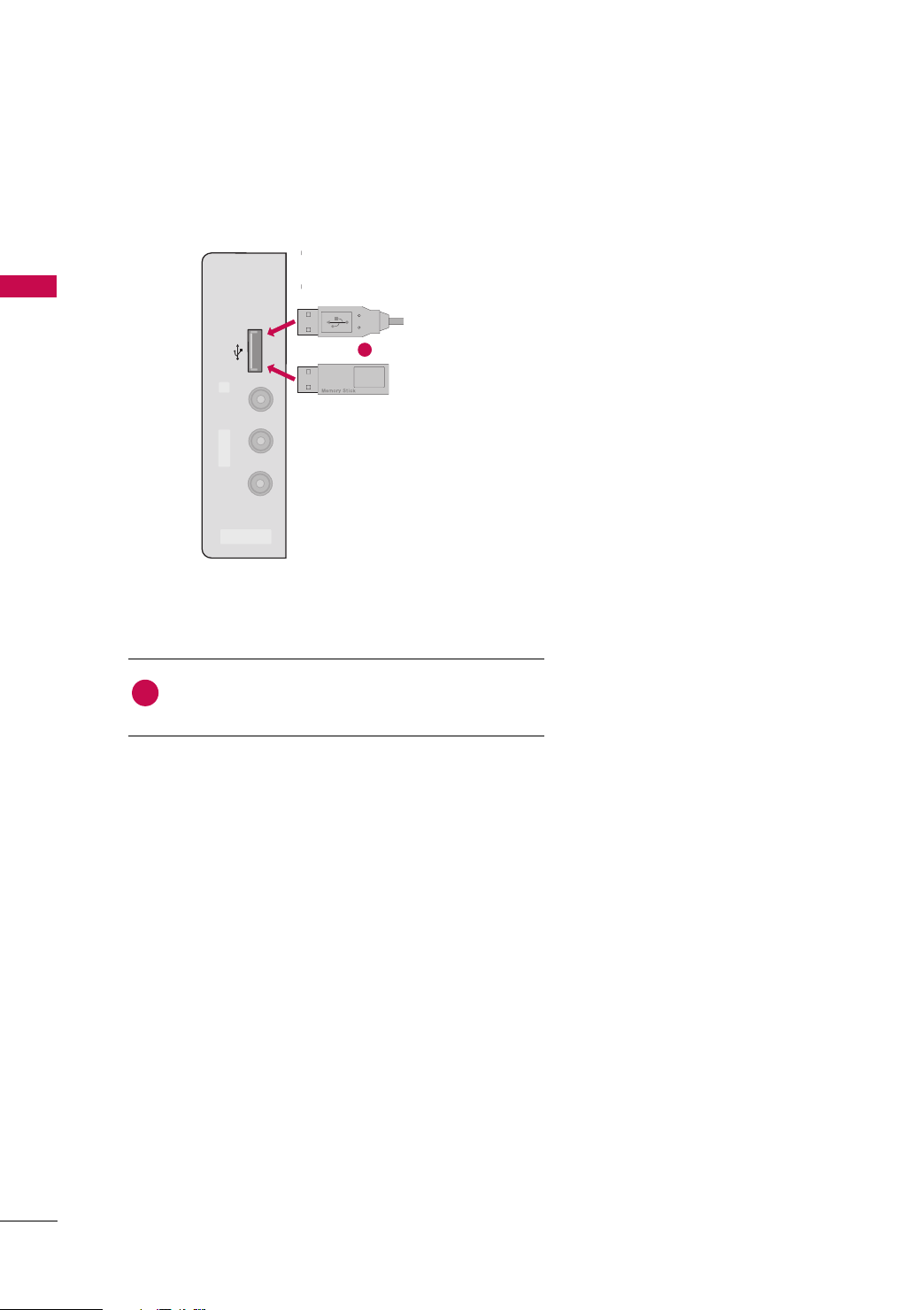
USB CONNECTION
■
Image shown may differ from your TV.
i.e)
(Except 42/50PQ10R)
or
1. How to connect
1
Connect the USB device to the
1
of TV.
2. How to use
■
After connecting the
tion. (
GG
pp.. 6600
UUSS BB II NN
UUSS BB II NN
)
jack, you use the USB func-
jack on the side
30
 Loading...