

LG 42PC5R, 42PC5R-ZB, 42PC5R1, 42PC5R1-ZD Service Manual

PLASMA TV
SERVICE MANUAL
CAUTION
BEFORE SERVICING THE CHASSIS,
READ THE SAFETY PRECAUTIONS IN THIS MANUAL.
CHASSIS : PP78A
MODEL : 42PC5R 42PC5R-ZB
42PC5R1 42PC5R1-ZD
website:http://biz.LGservice.com

- 2 -
CONTENTS
CONTENTS .............................................................................................. 2
SAFETY PRECAUTIONS ..........................................................................3
SPECIFICATION ........................................................................................4
ADJUSTMENT INSTRUCTION .................................................................6
TROUBLE SHOOTING ............................................................................15
BLOCK DIAGRAM...................................................................................23
EXPLODED VIEW .................................................................................. 24
EXPLODED VIEW PARTS LIST ............................................................ 25
REPLACEMENT PARTS LIST ............................................................... 26
SVC. SHEET ...............................................................................................
PRINTED CIRCUIT DIAGRAM ....................................................................
- 3 -
SAFETY PRECAUTIONS
Many electrical and mechanical parts in this chassis have special safety-related characteristics. These parts are identified by in the
Schematic Diagram and Replacement Parts List.
It is essential that these special safety parts should be replaced with the same components as recommended in this manual to prevent
X-RADIATION, Shock, Fire, or other Hazards.
Do not modify the original design without permission of manufacturer.
General Guidance
An isolation Transformer should always be used during the
servicing of a receiver whose chassis is not isolated from the AC
power line. Use a transformer of adequate power rating as this
protects the technician from accidents resulting in personal injury
from electrical shocks.
It will also protect the receiver and it's components from being
damaged by accidental shorts of the circuitry that may be
inadvertently introduced during the service operation.
If any fuse (or Fusible Resistor) in this monitor is blown, replace it
with the specified.
When replacing a high wattage resistor (Oxide Metal Film Resistor,
over 1W), keep the resistor 10mm away from PCB.
Keep wires away from high voltage or high temperature parts.
Due to high vacuum and large surface area of picture tube,
extreme care should be used in handling the Picture Tube.
Do not lift the Picture tube by it's Neck.
Leakage Current Cold Check(Antenna Cold Check)
With the instrument AC plug removed from AC source, connect an
electrical jumper across the two AC plug prongs. Place the AC
switch in the on position, connect one lead of ohm-meter to the AC
plug prongs tied together and touch other ohm-meter lead in turn to
each exposed metallic parts such as antenna terminals, phone
jacks, etc.
If the exposed metallic part has a return path to the chassis, the
measured resistance should be between 1MΩ and 5.2MΩ.
When the exposed metal has no return path to the chassis the
reading must be infinite.
An other abnormality exists that must be corrected before the
receiver is returned to the customer.
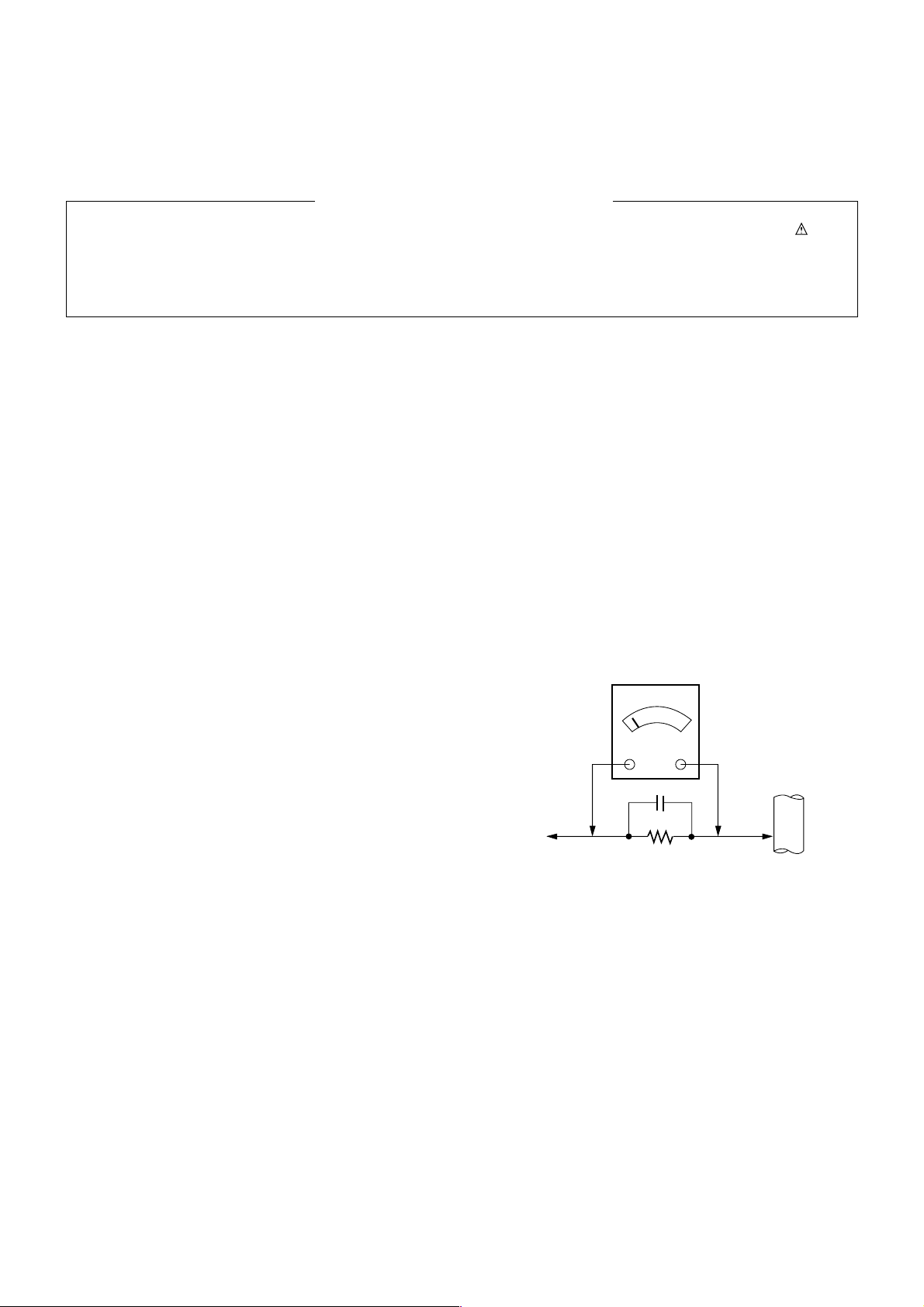
Leakage Current Hot Check (See below Figure)
Plug the AC cord directly into the AC outlet.
Do not use a line Isolation Transformer during this check.
Connect 1.5K/10watt resistor in parallel with a 0.15uF capacitor
between a known good earth ground (Water Pipe, Conduit, etc.)
and the exposed metallic parts.
Measure the AC voltage across the resistor using AC voltmeter
with 1000 ohms/volt or more sensitivity.
Reverse plug the AC cord into the AC outlet and repeat AC voltage
measurements for each exposed metallic part. Any voltage
measured must not exceed 0.75 volt RMS which is corresponds to
0.5mA.
In case any measurement is out of the limits specified, there is
possibility of shock hazard and the set must be checked and
repaired before it is returned to the customer.
Leakage Current Hot Check circuit
1.5 Kohm/10W
To Instrument's
exposed
METALLIC PARTS
Good Earth Ground
such as WATER PIPE,
CONDUIT etc.
AC Volt-meter
IMPORTANT SAFETY NOTICE
0.15uF

- 4 -
SPECIFICATIONS
NOTE : Specifications and others are subject to change without notice for improvement
.
V Application Range
This spec is applied to the 42” PLASMA TV used PP78A Chassis.
V Specification
Each part is tested as below without special appointment.
1) Temperature : 25±5°C (77±9°F), CST : 40±5
2) Relative Humidity: 65±10%
3) Power Voltage: Standard Input voltage (100-240V~, 50/60Hz)
* Standard Voltage of each product is marked by models.
4) Specification and performance of each parts are followed each drawing and specification by part number in accordance with SBOM.
5) The receiver must be operated for about 20 minutes prior to the adjustment.
V Test Method
1) Performance : LGE TV test method followed.
2) Demanded other specification
Safety : CE, IEC specification
EMC : CE, IEC
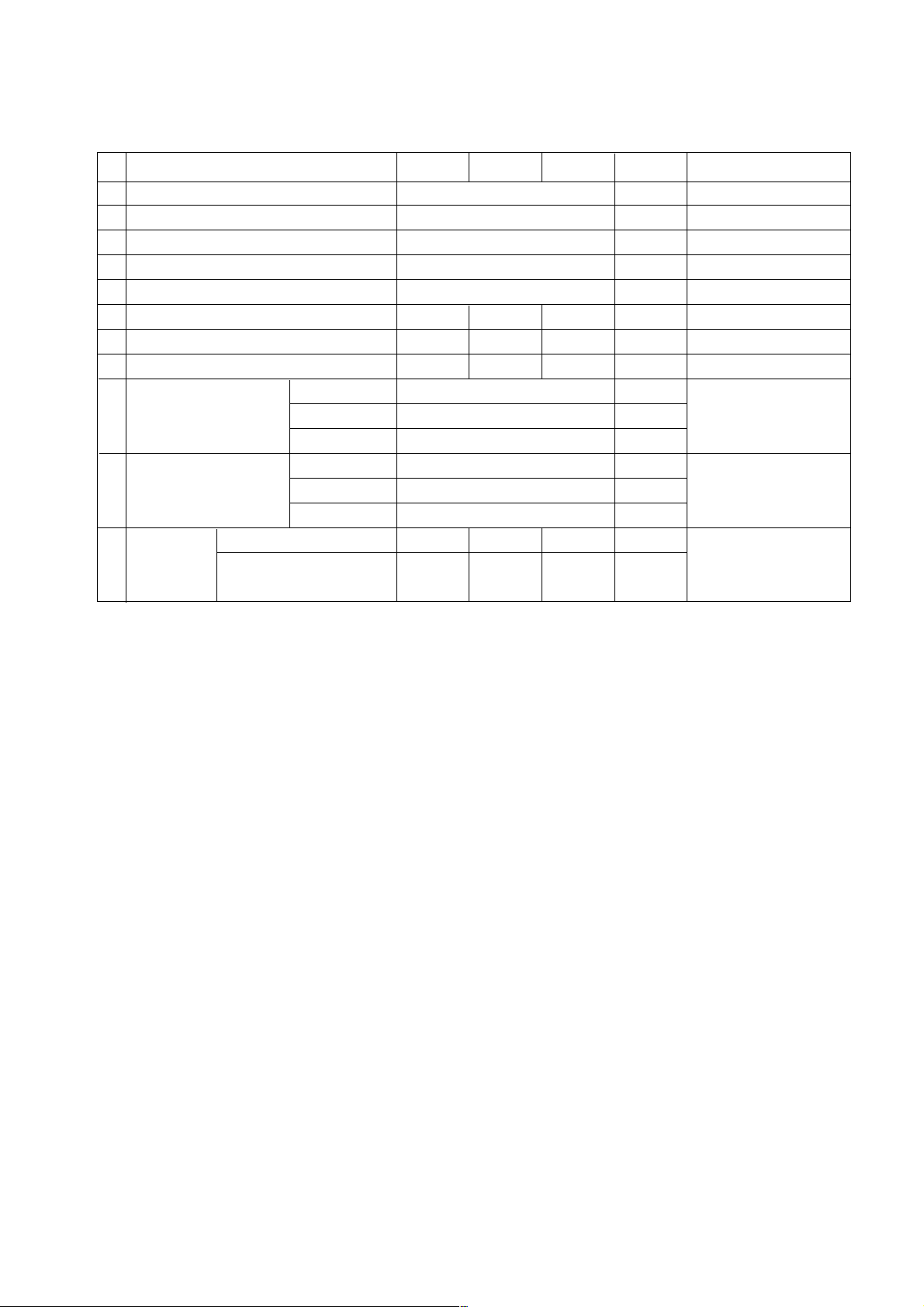
V General Specification ( 42”XGA Module with 40%)
Display Screen Device
Aspect Ratio
PDP Module
Operating Environment
Storage Environment
Input Voltage
1
2
3
4
5
6
No Item Specification Remark
42” Wide Color Display Module
16:9
PDP42X4,
RGB Closed Type
1)Temp. : 0~40deg
2)Humidity : 0~85%
3)Temp. : -20~60deg
4)Humidity : 0~85%
100-240V~, 50/60Hz
Plasma Display Panel
Clear Filter
LGE SPEC.
Maker : LG
Chassis
PP78A 42PC5R-ZB
42PC5R1-ZD
EU LG
Model Name Market Brand Remark
42PC5R-ZB
42PC5R1-ZD
Safety : IEC/EN60065, EMI : EN55013, EMS : EN55020EU
Model ApplianceMarket
TEST
Remark
- 5 -
V Module Specification (PDP42X4)
Display area
Outline dimension
Number of Pixels
Cell pitch
Color arrangement
Weight(net)
Weight(gross)
Item
Temperature
Operating Environment Humidity
Pressure
Temperature
Storage Environment Humidity
Pressure
Image stick Start time
minimization Low Brightness Arrival Time
mode
921.5 (H) * 519.0(V)±0.5
1005 (W) x 597 (H) x 60.7 (D)±1
1024 (H) x 768(V)
300um (H) x 676um (V)
RGB closed type
13.8 14.3 14.8
192.5 197.5 202.5
Min Typ Max
0 ~ 40
20 ~ 80
800 ~ 1100
-20 ~ 60
10 ~ 90
700 ~ 1100
4.5 5 5.5
14 15 16
1
2
3
4
5
6
7
8
9
No Item Remark
1Pixel=3RGB Cells
1Pixel=3RGB Cells
5EA 1Box
Remark
Altitude : 0 to 2000M
Altitude : 0 to 3000M
mm
mm
um
Kg
Kg
Unit
deg
%
hPa
deg
%
hPa
min
min
Min Typ Max Unit
- 6 -
ADJUSTMENT INSTRUCTION
1. Application Object
These instructions is applied all of the 42” PLASMA TV,
PP78A Chassis.
2. Note
(1) Because this is not a hot chassis, it is not necessary to use
an isolation transformer. However, the use of isolation
transformer will help protect test instrument.
(2) Adjustment must be done in the correct order.
(3) The adjustment must be performed in the circumstance of
25±5°C of temperature and 65±10% of relative humidity if
there is no specific designation.
(4) The input voltage of the receiver must keep 100-220V~,
50/60Hz.
(5) Before adjustment, execute Heat Run for 30 minutes.
3. Adjustment items
3.1. PCB assembly adjustment items
(1) Download the VCTP main software (IC500,VCT_Pro)
(2) Channel memory (IC501,EEPROM)
(3) Color carrier Adjustment
3.2. SET assembly adjustment items
(1) DDC Data input.
(2) Adjustment of White Balance.
(3) Factoring Option Data input.
4. PCB assembly adjustment method
(Using VCTP Download program)
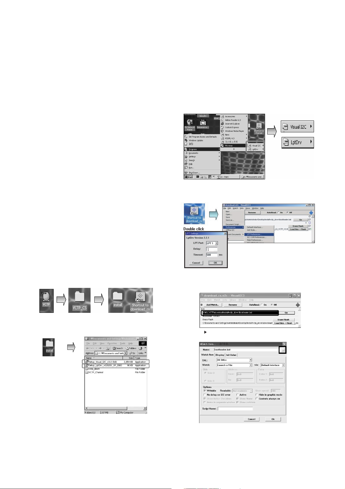
4-1. Download program installation
(1) Extract a Zip file.
(2) Visual I2C & LPT Driver Installation.
LPT Port Driver (LptDrv) Setups : Program Files > Micronas >
Visual I2C > Port_Driver
*Use for Windows 95/98 : Setup_LptDrv_v0104_9x.exe
*Use for Windows 2000/XP : Setup_LptDrv_v0202_XP_2000.exe
*
Use for Windows NT : Setup_LptDrv_v0104_NT.exe
(3) Verification.(Start > Programs > Micronas > Visual I2C or
LptDrv)
(4) LPT delay setting.(File > Preference > LPT preferences)
(5) Exchange the “bootloader.bat” file.
Click the red area
Double click the Red
Install the LPT Driver
Install the Visual I2C
*LPT SETTING
- Delay => 1
- Time out => 500 ms
- 7 -
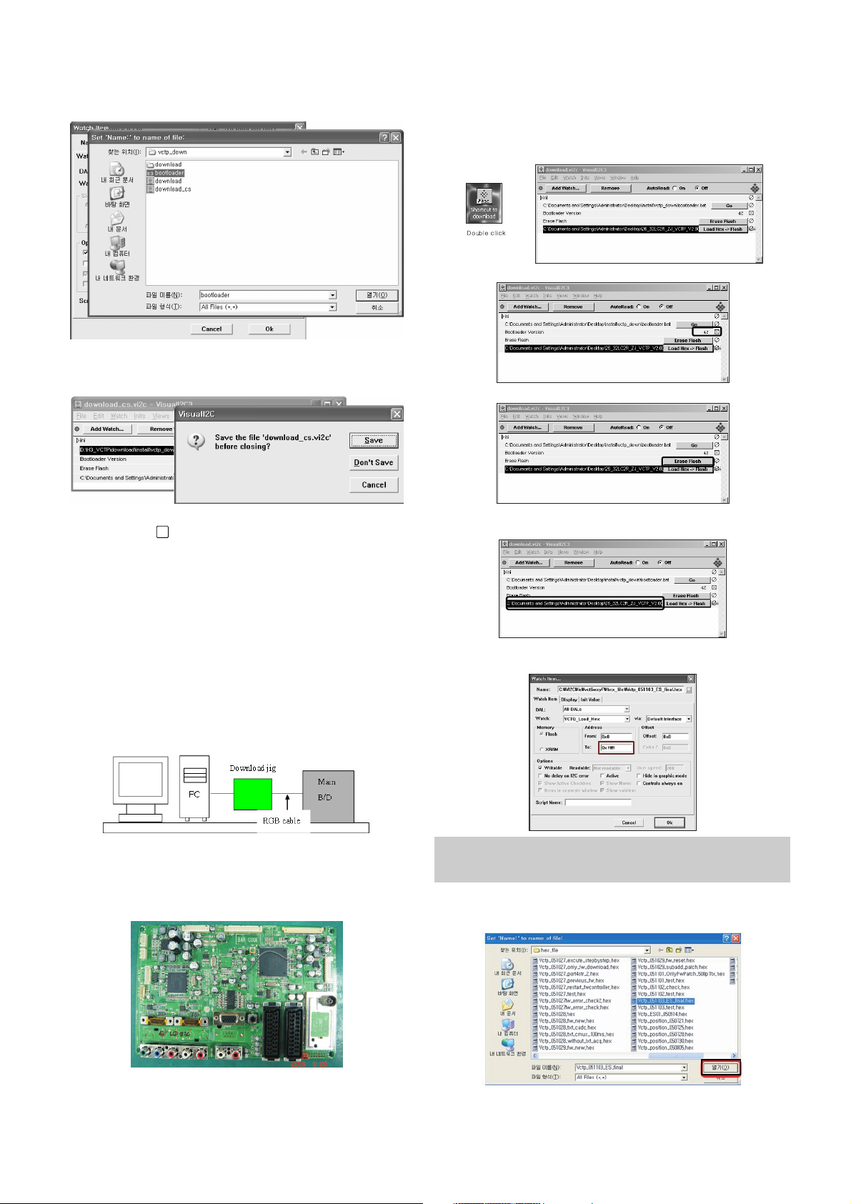
=> Select the "Bootloader.bat" file.
(install > VCTP_download > Bootloader)
=> Push "OK".
=>
Finish the program, after saving the file "download_cs.vi2c".
(if you click , the massage appears automatically)
5. S/W program download
5-1. Profile
: This is for downloading the s/w to the flash memory of the
vctp(IC500)
5-2. Required Test Equipment
(1) PC.
(2) Visual IIC program.
(3) Download jig.
5-3. Connection structure
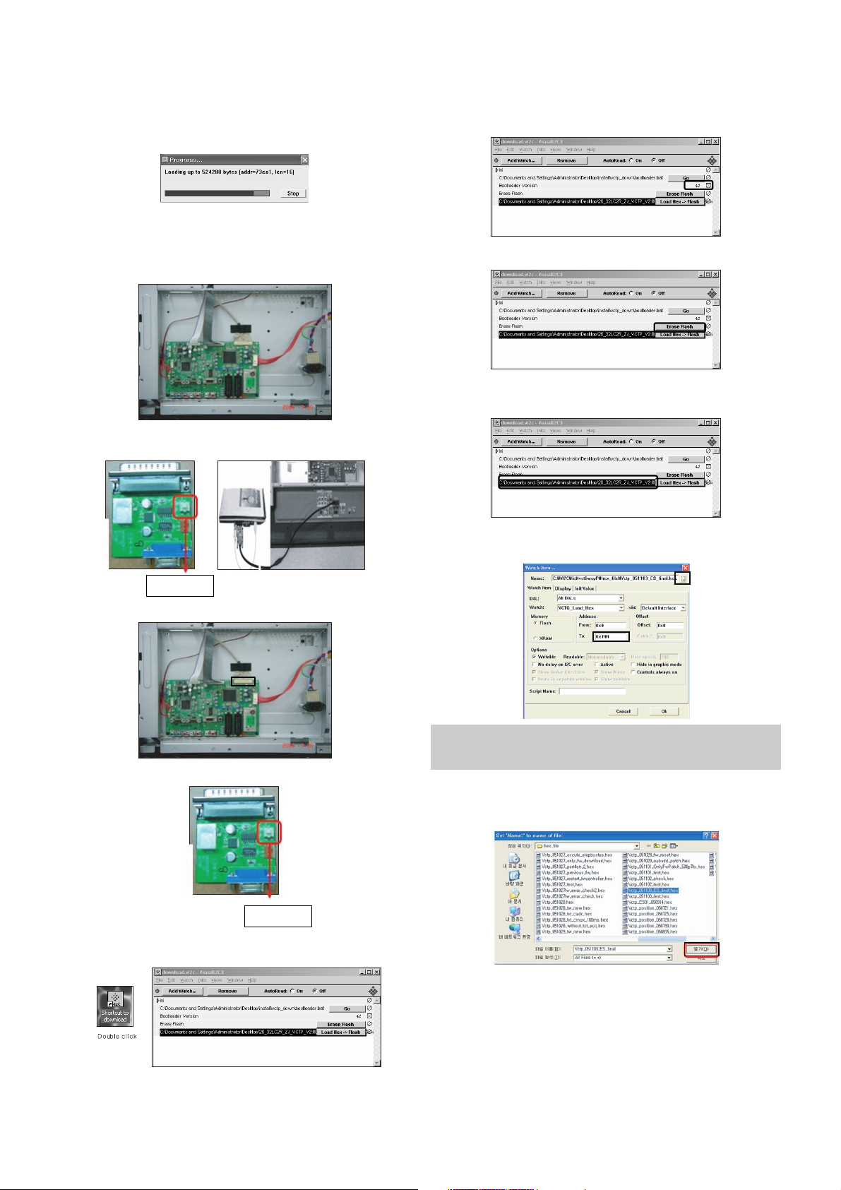
6. Download method
6-1. Download method 1 (PCB Ass’y)
(1) Connect the download jig to D-sub jack.
(2) Execute ‘Download.vi2c’ program in PC, then a main
window will be opened.
(3)
Double click the blue box and confirm "Bootloader Version" as 42.
(4) Click the "Erase Flash" button.
(5) Double click the download file low, then "edit" window will
be opened.
(6) Click the choice button in the “edit window”, then “file
choice window” will be opened.
(7) Choose the Hex file in folder and execute downloading
with click " open" button.
x
You must verify the words of “0xfffff” in the black box of figure.
(In case of H3 Service it is 0x7ffff : If you make H4 service after
the H3 service, there could be some problem)
- 8 -
(8) Click OK button at the "edit window".
(9) Under Downloading process.
(10) If download is failed, for example "No acknowledge from
slave". Execute download again from(1).
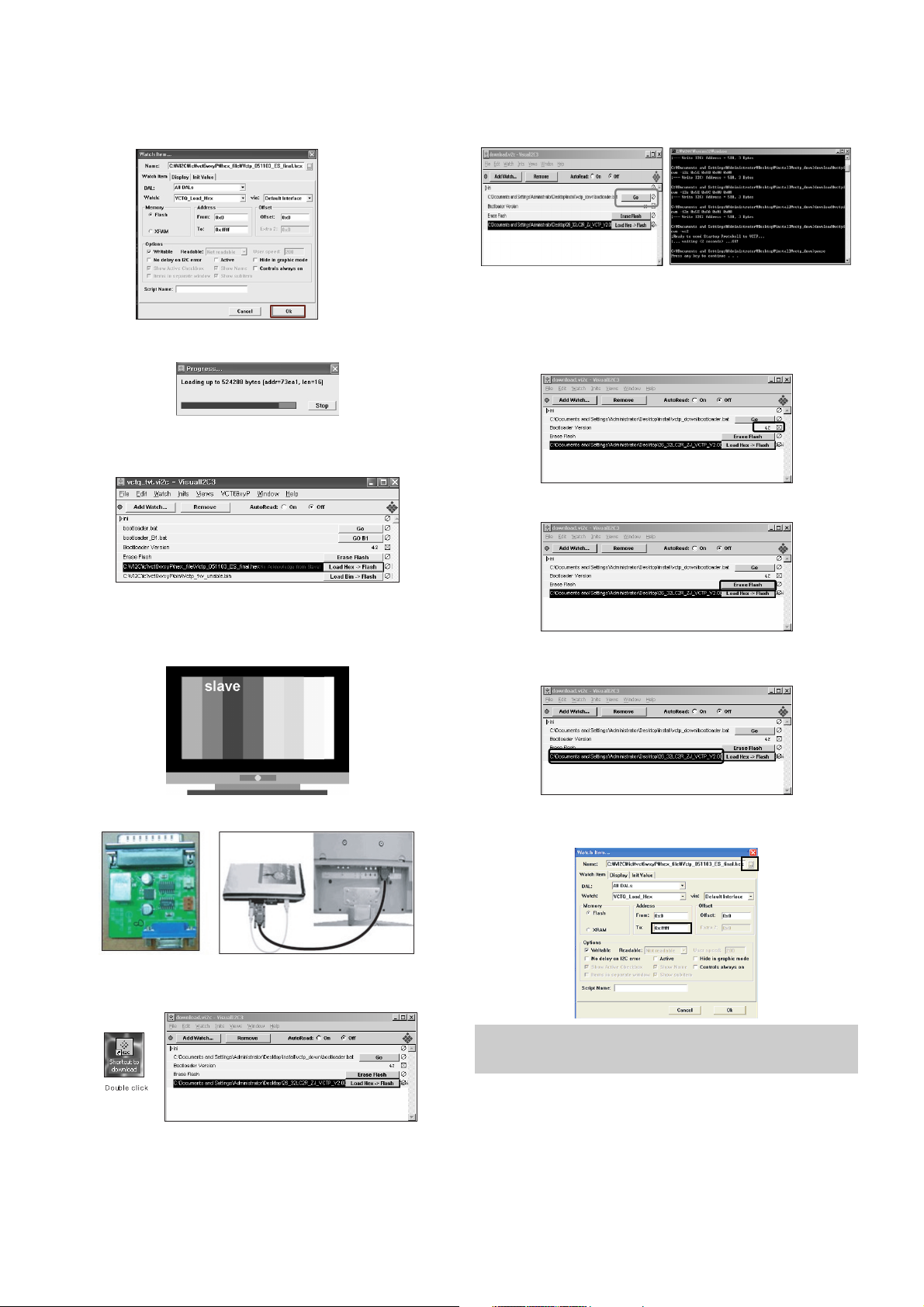
6-2.Download method 2 (AV Plate Ass’y)
(1) Push S/W ‘ON" (connect SCL to GND using switch at Jig )
and connect the download jig to D-sub jack.
(2) Supply the power (Stand-by 5V) and wait for 3 seconds.
(3)
Push the S/W off.(Disconnect SCL to GND using switch at jig).
(4) Execute ‘Download.vi2c’ program in PC, then a main
widow will be opened.
(5)
Double click the blue box and confirm "Bootloader Version" as 42
.
(6) Click the "Erase Flash" button.
(7) Double click the download file low then, "edit" window will
be opened.
(8) Chick the choice button I n the "edit window", then "file
choice window’ will be opened.
(9) Click the “load > flash” button.
(10) Choose the Hex file in folder and execute downloading
with click "open button".
Push S/W
Push S/W
You must verify the words of “0xfffff” in the black box(A) of figure.
(In case of H3 Service it is 0x7ffff : If you make H4 service after
the H3 service, there could be some problem)
A
- 9 -
(11) Click OK button at the "edit window".
(12) Under Downloading progress.
(13) If download is failed, for example "No acknowledge from
slave", execute download again from (1).
6-3.Download method 3 (SET)
(1) Push the “Tilt” button in an Adjust Remocon Then the
PLASMA TV will change a “slave mode”.
(2) Connect Zig to TV using a D-sub cable.
(3) Execute ‘Download_CS.vi2c’ program in PC, then a main
widow will be opened.
(4) Click "GO" button.
If you don’t push the “go” , the Hex file would not be
downloaded although the download proceeds normally at
first glance.
(5) Double click the blue box and confirm "Bootloader
Version" as 42.
(6) Click the "Erase Flash" button.
(7) Double click the download file low then, "edit" window will
be opened.
(8) Chick the choice button I n the "edit window", then "file
choice window’ will be opened.
(9) Click the “load > flash” button.
A
You must verify the words of “0xfffff” in the black box(A) of figure.
(In case of H3 Service it is 0x7ffff : If you make H4 service after
the H3 service, there could be some problem)
- 10 -
(10) Choose the Hex file in folder and execute downloading
with click "open button".
(11) Click OK button at the "edit window".
(12) Under Downloading progress.
(13) If download is failed, for example "No acknowledge from
slave", execute download again from (1).
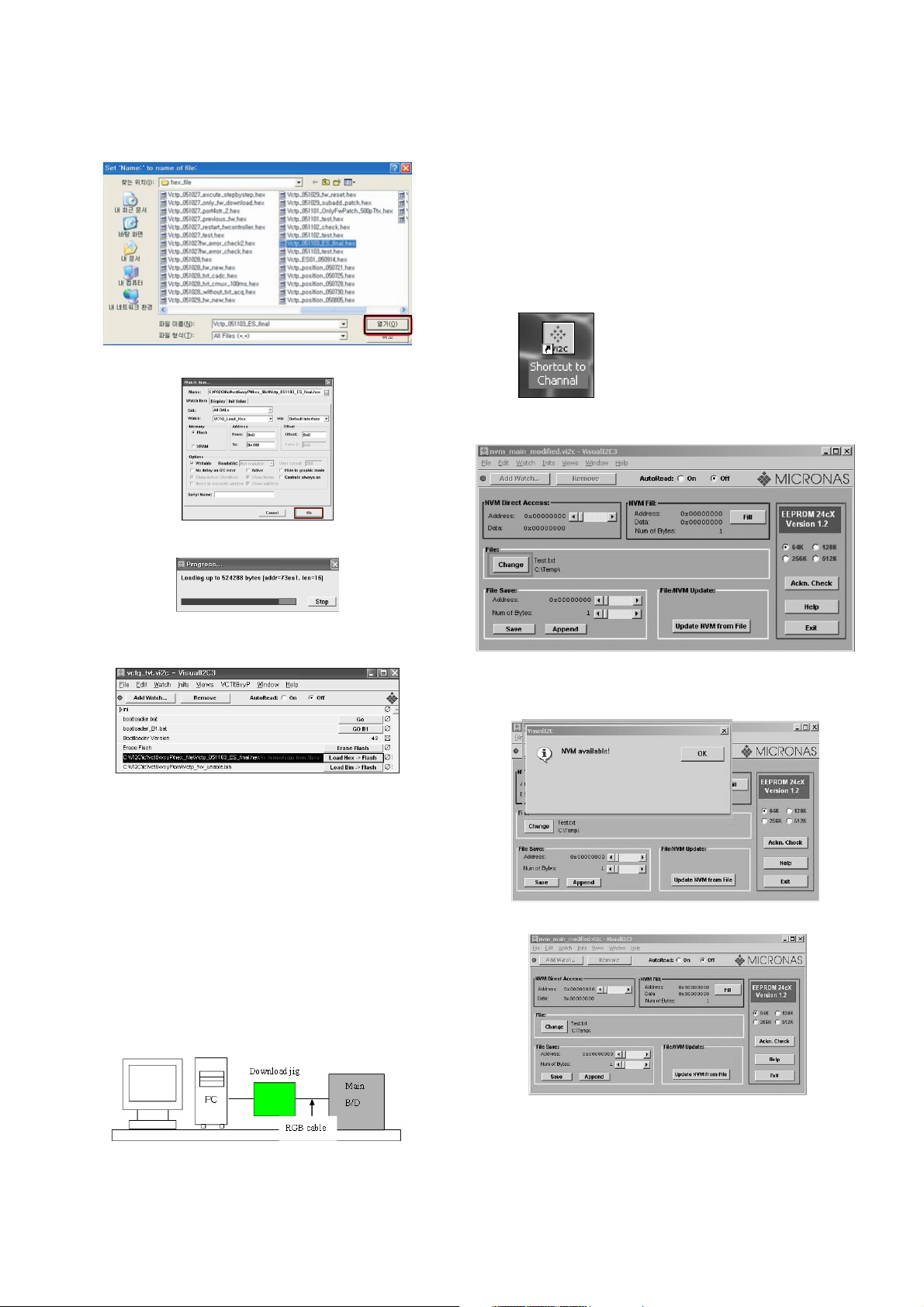
7. Channel memory download
7-1. Profile
: This is for downloading the s/w to the flash memory of the
vctp(IC500)
7-2. Required Test Equipment
(1) PC.
(2) Visual IIC program.
(3) Download jig.
7-3. Connection structure
(1) Connect the download jig to D-sub jack.
(2) Execute ‘Channel.vi2c’ program in PC, then a main
window will be opened.
7-4. Connection condition
(1) IC name and circuit number : VCTP and IC500.
(2) Use voltage : 3.3V.
(3) SCL : 15pin.
(4) SDA : 12pin.
(5) Tact time : about 3seconds.
7-5. Download method
(1) Connect the download jig to D-sub jack.
(2) ‘Execute ‘Channal vi2c’ program in PC, then a main
window will be opened.
(3) Push the button change and select the Channel memory
data.
(4) Check the communication is OK or not.
=> Push the Read area (Ackn. Check) and check Cyan area
is OK message.
(5) Push the Update NVM from File
- 11 -
8. Tool Option Area Option Change
8-1. Profile
:
Must be changed the option value because being different with
some setting value depend on module, inch and market.
8-2. Required Test Equipment
1) Adjustment remocon.
8-3. Adjustment method
Before PCB check, have to change the Tool option and Area option.
Option values are below.
(If on changed the option, the input menu can differ the model spec.)
The input methods are same as other chassises.(Use adj Key
on the Adjust Remocon)
9. Color carrier Adjustment
(Inspection process)
9-1. Profile
: To have the margin about the deviation of colorcarrier to
satisfy the spec.
9-2. Required Test Equipment
1) Adjustment remocon.
2) Pal RF signal.
9-3. Connection
: TV set should connected with the pal RF signal(EU 5CH).
9-4. Adjustment method
(1) tuning the RF signal
ZB, TB : PAL Philips Pattern (with Color Bar)
(2) push the “adj” key in the adjustment remocon.
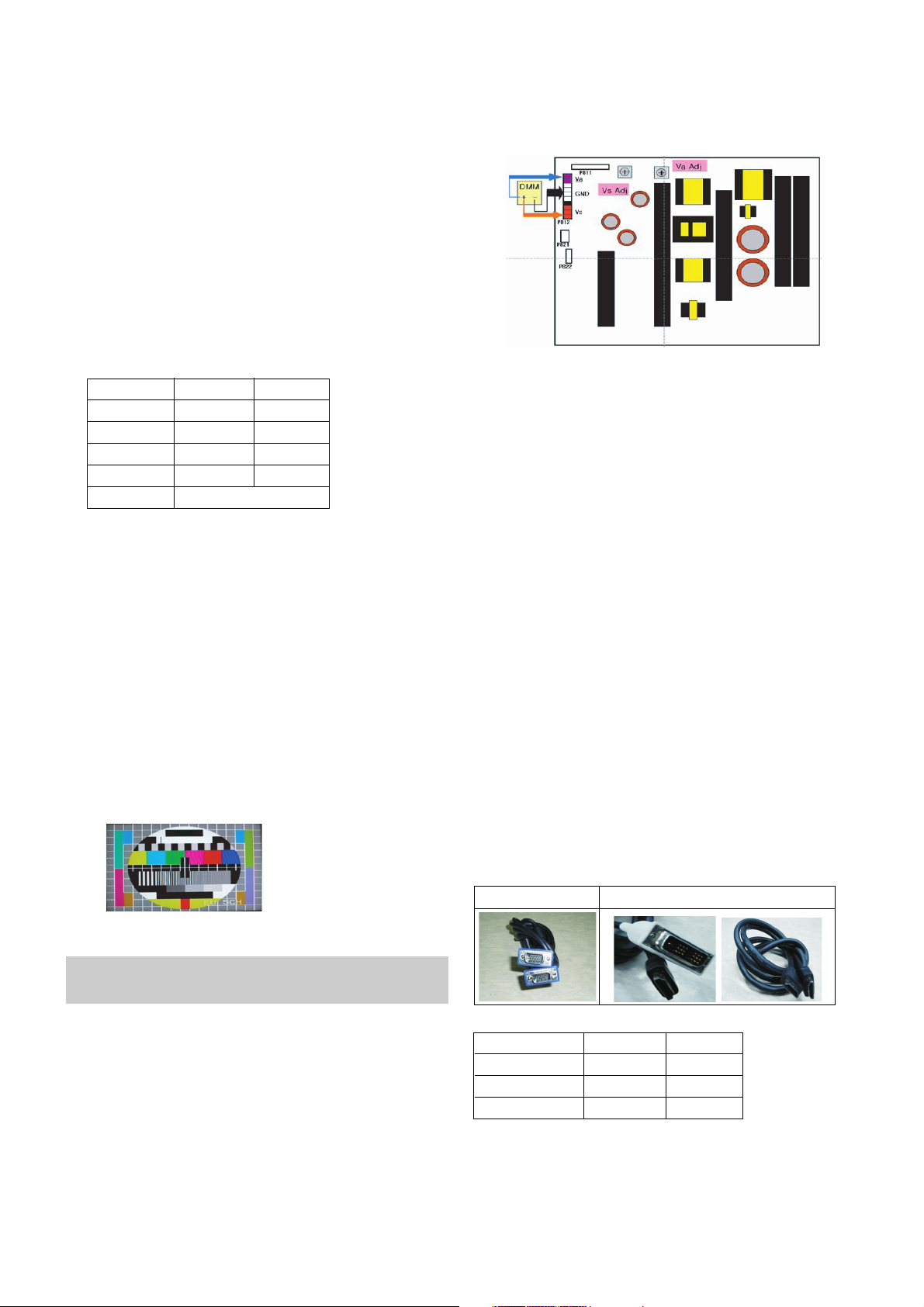
10. POWER PCB Assy Voltage
Adjustments
(Va, Vs Voltage adjustments)
10-1. Profile
: To supply the Va, Vs voltage that the module want.
10-2. Required Test Equipment
(1) Stick for adjustment.
(2) DMM.
10-3. Connection structure
10-4. Connection Diagram for Measuring
: refer to (Fig. 1)
10-5. Adjustment Method
(1) Va Adjustment
1) After receiving 100% Full White Pattern, HEAT RUN.
2) Connect + terminal of D. M..M. to Va pin of P812, connect
-terminal to GND pin of P812.
3)
After turning VR901,voltage of D.M.M adjustment as
same as Va voltage which on label of panel right/top.
(deviation;
±
0.5V)
(2) Vs Adjustment
1) Connect + terminal of D. M..M. to Vs pin of P812, connect
-terminal to GND pin of P812.
2)
After turning VR951, voltage of D.M.M adjustment as
same as Vs voltage which on label of panel right/top.
(deviation ;
±0.5V)
11. EDID
(The Extended Display Identification Data )
/DDC(Display Data Channel) download
11-1. Profile
: To be possible for plug and play.
11-2. EDID Data
* Caution
- Use the proper signal cable for EDID Download.
- Never connect HDMI & D-SUB Cable at the same time.
- Use the proper cables below for EDID Writing.
* EDID Data
Tool Option
Inch ZB TB
42(VGA) 02244 04292
42(XGA) 02252 04300
50 02260 04308
Area Option Depend on PR
Item
Manufacturer ID
Version
Revision
Condition
GSM
Digital : 1
Digital : 3
Hex Data
1E6D
01
03
For RGB EDID For HDMI EDID
(Fig. 1) Connection Diagram of power adjustment for measuring.
Each PCB assembly must be checked by check JIG set.
(Because power PCB Assembly damages to PDP Module,
especially be careful)
- 12 -
<Analog (RGB) >
< Digital1 (HDMI/DVI1) >
< Digital2 (HDMI/DVI2) >
=> Detail EDID Options are below(a, b, c, d, e)
1. Product ID
2. Serial No : Controlled on production line
3. Month, Year : Controlled on production line
ex) Monthly: '03' => '03'
Year: '2005' => '0F'
4. Model Name : model name -> LG TV
- LG TV
5. Checksum (7EH) -> Changeable by total EDID data.
11-3. Required Test Equipment
(1) Adjusting PC with S/W for writing EDID Data.
(S/W : EDID TESTER Ver.2.5)
(2) A Jig for EDID Download.
(3) Cable : Serial(9Pin or USB) to D-sub 15Pin cable, D-sub
15Pin cable, DVI to HDMI cable.
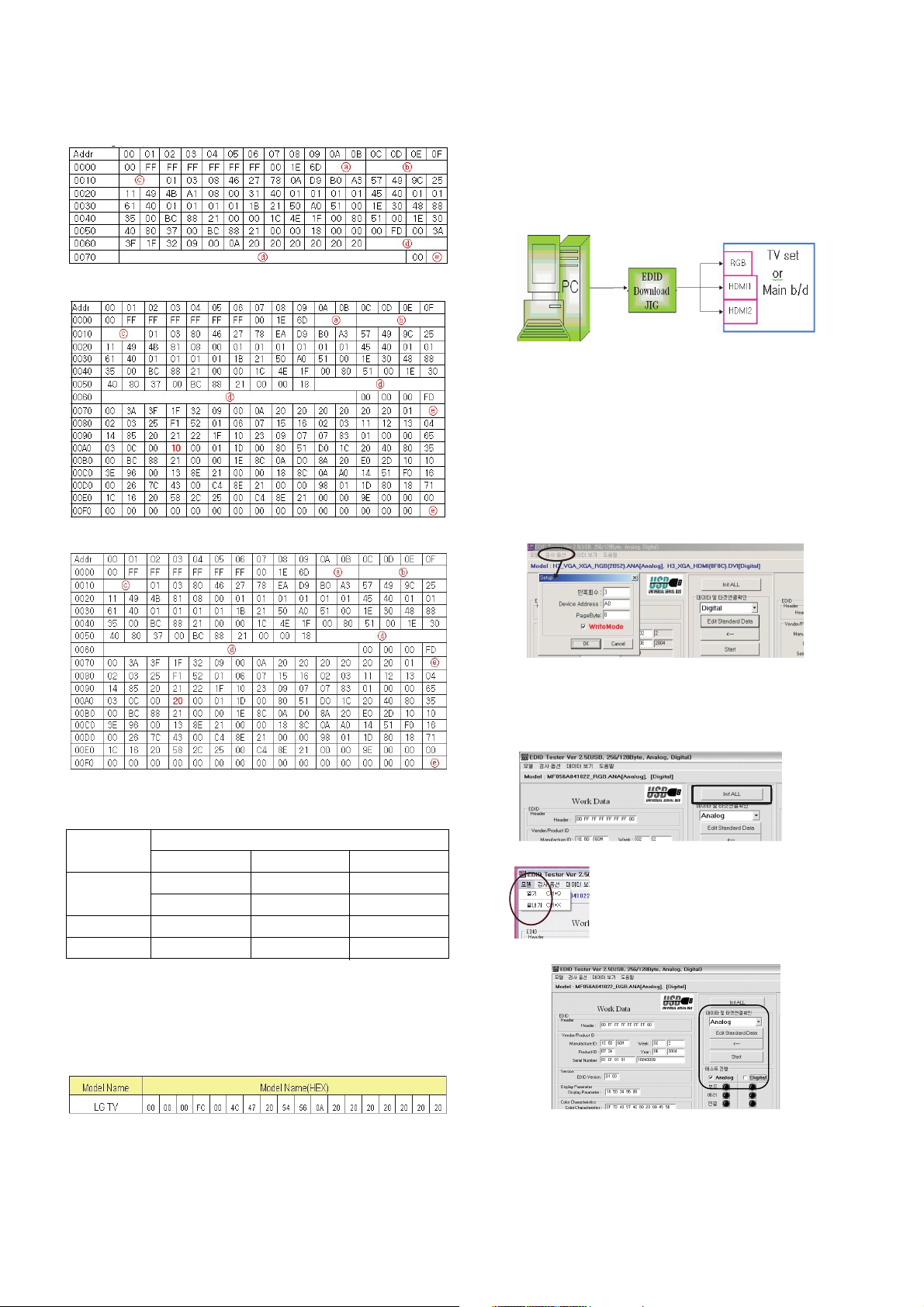
11-4. Preparation for Adjustment
(1) As above (Fig. 2), Connect the Set, EDID Download Jig,
PC & Cable.
(2) Turn on the PC & EDID Download Jig. And Execute the
S/W : EDID TESTER Ver 2.5.
(3) Set up S/W option.
Repeat Number : 5
Device Address : A0
PageByte : 8
(4) Power on the Set.
11-5. Sequence of Adjustment
(1) DDC data of Analog-RGB
1) Init the data.
2) Load the EDID data.(Open File).
[ Analog
-
RGB
: PP78A_RGB.ANA ]
[ Digital-HDMI1 :
PP78A_HDMI1.DVI ]
[ Digital-HDMI2 :
PP78A_HDMI2.DVI ]
3) Set the S/W as below.
Model
Name
42PC5R
42PC51
50PC5R
50PC51
DEC
40079 (A)
40080 (D)
50007 (A)
50008 (D)
Product ID
HEX
9C8F
9C90
C357
C358
EDID table
8F9C
909C
57C3
58C3
(Fig. 2) Connection Diagram of DDC download
Open FileOpen File
 Loading...