

Page 1

PLASMA TV
SERVICE MANUAL
CAUTION
BEFORE SERVICING THE CHASSIS,
READ THE SAFETY PRECAUTIONS IN THIS MANUAL.
CHASSIS :PA75C
MODEL : 42PC5DH 42PC5DH-UL
website:http://biz.LGservice.com
Internal Use Only
Page 2

SAFETY PRECAUTIONS
Many electrical and mechanical parts in this chassis have special safety-related characteristics. These parts are identified by in the
Schematic Diagram and Replacement Parts List.
It is essential that these special safety parts should be replaced with the same components as recommended in this manual to prevent
X-RADIATION, Shock, Fire, or other Hazards.
Do not modify the original design without permission of manufacturer.
General Guidance
An lsolation Transformer should always be used during the
servicing of a receiver whose chassis is not isolated from the AC
power line. Use a transformer of adequate power rating as this
protects the technician from accidents resulting in personal injury
from electrical shocks.
It will also protect the receiver and it's components from being
damaged by accidental shorts of the circuitary that may be
inadvertently introduced during the service operation.
If any fuse (or Fusible Resistor) in this monitor is blown, replace it
with the same specified type.
When replacing a high wattage resistor (Oxide Metal Film Resistor,
over 1W), keep the resistor 10mm away from PCB.
Keep wires away from high voltage or high temperature parts.
Leakage Current Cold Check(Antenna Cold Check)
With the instrument AC plug removed from AC source, connect an
electrical jumper across the two AC plug prongs. Place the AC
switch in the on positioin, connect one lead of ohm-meter to the AC
plug prongs tied together and touch other ohm-meter lead in turn to
each exposed metallic parts such as antenna terminals, phone
jacks, etc.
If the exposed metallic part has a return path to the chassis, the
measured resistance should be between 1MΩ and 5.2MΩ.
When the exposed metal has no return path to the chassis the
reading must be infinite.
An other abnormality exists that must be corrected before the
receiver is returned to the customer.
Leakage Current Hot Check (See below Figure)
Plug the AC cord directly into the AC outlet.
Do not use a line Isolation Transformer during this check.
Connect 1.5K/10watt resistor in parallel with a 0.15uF capacitor
between a known good earth ground (Water Pipe, Conduit, etc.)
and the exposed metallic parts.
Measure the AC voltage across the resistor using AC voltmeter
with 1000 ohms/volt or more sensitivity.
Reverse plug the AC cord into the AC outlet and repeat AC voltage
measurements for each esposed metallic part. Any voltage
measured must not exceed 0.75 volt RMS which is corresponds to
0.5mA.
In case any measurement is out of the limits sepcified, there is
possibility of shock hazard and the set must be checked and
repaired before it is returned to the customer.
Leakage Current Hot Check circuit
CANADA: LG Electronics Canada, Inc. 550 Matheson
Boulevard East Mississauga, Ontario L4Z 4G3
USA : LG Customer Interactive Center
P.O.Box 240007, 201 James Record Road Huntsville,
AL 35824
Digital TV Hotline 1-800-243-0000
IMPORTANT SAFETY NOTICE
0.15uF
To Instrument's
exposed
METALLIC PARTS
AC Volt-meter
Good Earth Ground
such as WATER PIPE,
CONDUIT etc.
1.5 Kohm/10W
Page 3

Copyright © 2007 LG Electronics. Inc. All right reserved.
Only for training and service purposes
LGE Internal Use Only
SPECIFICATIONS.................................................................4
ADJUSTMENT INSTRUCTIONS ..........................................5
BLOCK DIAGRAM ..............................................................11
EXPLODED VIEW...............................................................20
EXPLODED VIEW PARTS LIST .........................................21
REPLACEMENT PARTS LIST............................................22
SCHEMATIC DIAGRAM..........................................................
PRINTED CIRCUIT BOARDS.................................................
TABLE OF CONTENTS
Page 4

Copyright © 2007 LG Electronics. Inc. All right reserved.
Only for training and service purposes
LGE Internal Use Only
SPECIFICATIONS
-
The specifications shown above may be changed without prior notice for quality improvement.
MODELS
Dimensions
(Width x Height x Depth)
Weight
Power requirement
Television System
Program Coverage
External Antenna Impedance
Environment condition
Including stand
Excluding stand
including stand
excluding stand
Operating Temperature
Operating Humidity
Storage Temperature
Storage Humidity
42PB4DA
(42PB4DA-UA)
44.5 x 30.2 x 12.2 inches
1130.0 x 768.1 x 310.4mm
44.5 x 28.1 x 3.3 inches
1130.0 x 715.0 x 85.0 mm
75.8 pounds / 34.4 kg
68.0 pounds / 30.8 kg
NTSC-M, ATSC, 64 & 256 QAM
VHF 2-13, UHF 14-69, CATV 1-135, DTV 2-69, CADTV 1-135
50PB4DA
(50PB4DA-UA)
51.5 x 35.7 x 14.6 inches
1308.0 x 906.1 x 370.0 mm
51.5 x 33.3 x 3.5 inches
1308.0 x 845.0 x 89.5 mm
93.5 pounds / 42.4 kg
83.1 pounds / 37.7 kg
AC100-240V ~ 50/60Hz
75 ohm
32 ~ 104°F (0 ~ 40°C)
Less than 80%
-4 ~ 140°F (-20 ~ 60°C)
Less than 85%
60PB4DA
(60PB4DA-UA)
60.9 x 41.8 x 17.6 inches
1548.0 x 1061.0 x 448.0 mm
60.9 x 38.9 x 3.9 inches
1548.0 x 988.0 x 98.5 mm
163.1 pounds / 81.0 kg
135.6 pounds / 61.5 kg
Page 5
Copyright © 2007 LG Electronics. Inc. All right reserved.
Only for training and service purposes
LGE Internal Use Only
1. Application Range
This spec sheet is applied all of the PDP TV, PA75C chassis.
2. Specification
(1) Because this is not a hot chassis, it is not necessary to use
an isolation transformer. However, the use of isolation
transformer will help protect test equipment.
(2) Adjustments must be done in the correct order.
(3) The adjustments must be performed in the circumstance of
25±5°C of temperature and 65±10% of relative humidity if
there is no specific designation.
(4) The input voltage of the receiver be must kept 110V, 60Hz
when adjusting.
(5) The receiver must be operational for about 15 minutes
prior to the adjustments.
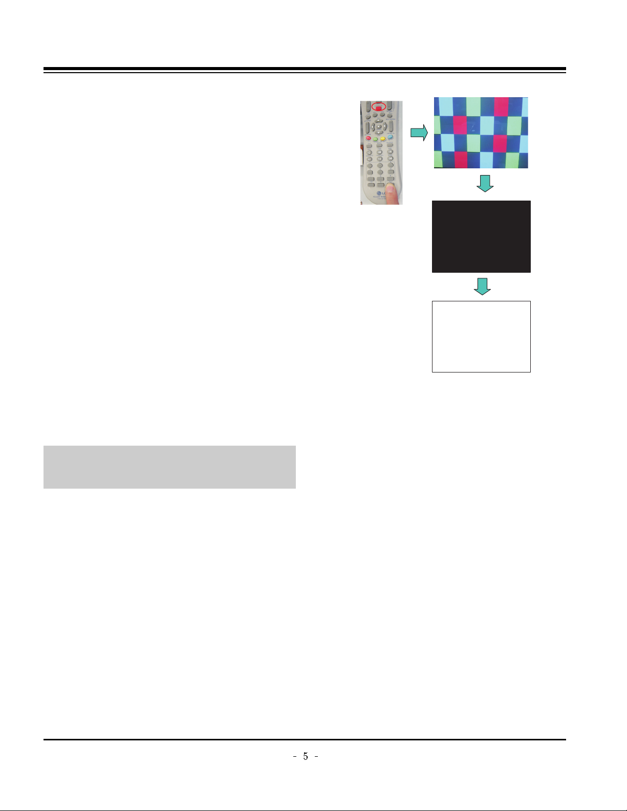
1) After receiving 100% white pattern, the receiver must be
operated prior to adjustment. (Or 8. Test Pattern
condition in EZ - Adjust)
2) Enter into White Pattern
- Press POWER ON Key on the Service Remote
Control (S R/C)
- Enter the Ez - Adjust by pressing ADJ Key on the
Service Remote Control (S R/C).
- Select 10. Test Pattern using the CH +/- Key and
select the White by pressing the direction Key.
Display the 100% Full White Pattern.
[ Set is activated HEAT-RUN without signal generator in
this mode.
O HEAT RUN
Preliminary action is applied to the test for afterimage
discharge detection, and 100% FULL WHITE PATTERN
must be operated automatically.
O Test for afterimage discharge detection
1) Pressing Power On key
- Only operating by pressing Power On key
2) Full Test Pattern(2 min 30sec) --> Full Black
Pattern(30sec) --> Full White Pattern(maintenance)
- Full White Pattern when the main power is turned on
again after being turned off
3) Pattern Mode is deselected by pressing CH +/-, Exit Key.
[ Set is activated HEAT-RUN without signal generator in this
mode.
ADJUSTMENT INSTRUCTIONS
If you turn on a still screen more than 20 minutes (Especially
Digital pattern(13 CH), Cross Hatch Pattern), an afterimage
may occur in the black level part of the screen.
Test Pattern 2min 30sec
Test Pattern 30sec
Page 6

Copyright © 2007 LG Electronics. Inc. All right reserved.
Only for training and service purposes
LGE Internal Use Only
3. PSU(Power Supply Unit) Voltage
Adjustment
(Va, Vs Voltage Adjustment)
Adjust the voltages Va and Vs supplied from the PSU to the
module within the specified range of each module to supply
the stable power
3-1. Test Equipment
(1) D.M.M 1EA
(2) Voltage adjustment bar
3-2. Adjustment(60”)
(1) Va Voltage Adjustment
1) Connect + terminal of D.M.M to Va pin of P812 and
connect – terminal to GND pin of P812.
2) Adjust VR901 voltage to match that of the label on the
Top/Right of the panel. (Deviation : ±0.5V)
(2) Vs Voltage Adjustment
1) Connect + terminal of D.M.M to Vs pin of P812 and
connect – terminal to GND pin of P812.
2) Adjust VR951 voltage to match that of the label on the
Top/Right of the panel. (Deviation : ±0.5V)
3-3. Adjustment (50”)
(1) Va Adjustment
1) Connect + terminal of D.M.M to Va pin of P12 and
connect – terminal to GND pin of P12.
2) Adjust VR951 voltage to match that of the label on the
Top/Right of the panel. (Deviation : ±0.5V)
(2) Vs Adjustment
1) Connect + terminal of D.M.M to Vs pin of P12 and
connect – terminal to GND pin of P12.
2) Adjust VR901 voltage to match that of the label on the
Top/Right of the panel. (Deviation : ±0.5V)
3-4. Adjustment(42”)
(1) Va Voltage Adjustment
1) Connect + terminal of D.M.M to Va pin of P812 and
connect – terminal to GND pin of P812.
2) Adjust VR901 voltage to match that of the label on the
Top/Right of the panel. (Deviation : ±0.5V)
(2) Vs Voltage Adjustment
1) Connect + terminal of D.M.M to Vs pin of P812 and
connect – terminal to GND pin of P812.
2) Adjust VR951 voltage to match that of the label on the
Top/Right of the panel. (Deviation : ±0.5V)
ADJUSTMENT INSTRUCTIONS
Each PCB assembly must be checked by check JIG set.
(Because power PCB Assembly damages to PDP Module,
especially be careful)
Connection Diagram of Power Adjustment for Measuring
(Power Board): 60”
Connection Diagram of Power Adjustment for Measuring
(Power Board): 50”
Connection Diagram of Power Adjustment for Measuring
(Power Board): 42”(EAY32808901)
Page 7

Copyright © 2007 LG Electronics. Inc. All right reserved.
Only for training and service purposes
LGE Internal Use Only
4. Component 480i/1080p RGB
1080p Adjustment
Component 480i/1080p RGB 1080p adjustment to set the
black level and the Gain to optimum.
4-1. Test Equipment
(1) Service R/C
(2) 801GF(802B, 802F, 802R) or MSPG925FA Pattern
Generator (480i/1080i The Horizontal 100% Color Bar
Pattern adjust to within 0.7±0.1Vp-p)
[ Because the above pattern can differ by the model and
pattern for each device, you must check the pattern first.
4-2. ADC 480i Component1 Adjustment
(1) Check the connection Component1 to the Test Equipment.
(MSPG-925FA => Model: 209, Pattern: 65)
(2) Select Component1 as the input with 100% Horizontal
Color Bar Pattern(HozTV31Bar) in 480i Mode and select
‘Normal’ in screen.
(3) After receiving signal for at least 1 second, press the ADJ
Key on the Service R/C to enter the ‘Ez - Adjust’ and select
the ‘3. ADC 480i Comp1’.
Pressing the Enter Key to adjust automatically.
(4) When the adjustment is over, 'ADC Component1 Success’
is displayed.
(5) If the adjustment has errors, 'ADC Component1 480i Fail’
is displayed. And error massage(‘Component1 Not
Connected’ or ‘Not Valid Format’ or ‘Check Signal Status’)
is displayed for 1 second.
4-3. ADC 1080i Component1/RGB
Adjustment
(1) Check the connection Component1, RGB to the Test
Equipment (MSPG-925FA => Model: 225, Pattern: 65)
(2) Select Component1 as the input with 100% Horizontal
Color Bar Pattern(HozTV31Bar) in 1080i Mode and select
‘Normal’ in screen.
(3) After receiving signal for at least 1 second, press the ADJ
Key on the Service R/C to enter the ‘Ez - Adjust’ and select
the ‘4. ADC 1080i Comp1/RGB’.
Pressing the Enter Key to adjust automatically component1.
(4) When the adjustment is over, 'ADC Component1 Success’
is displayed. If the adjustment has errors, 'ADC
Component1 1080i Fail’ is displayed.
(5) After the Component1 adjustment is over, convert the
RGB-DTV Mode and start RGB adjustment.
When the adjustment is over, 'ADC RGB 1080P Success’
is displayed.
(6) Readjust after confirming the case Pattern or adjustment
condition where the adjustment errors.
Error massage is ‘Component1 Not Connected’ or ‘Not
Valid Format’ or ‘Check Signal Status’.
(7) After adjustment is complete, exit the adjustment mode by
pressing the ADJ KEY.
5. EDID(The Extended Display
Identification Data)/DDC
(Display Data Channel) Download
It is the feature to implement the “Plug and Play” which
automatically reconfigures the user’sl environment to directly
use by exchanging information without any command directly
to the PC or the monitor by the user, which is established by
the VESA
5-1. HDMI EDID Data Input
(1) Required Test Equipment
1) PC, Jig for adjusting DDC. (PC serial to D-sub
Connection equipment)
2) S/W for writing DDC(EDID data write & read)
3) D-Sub cable
4) Jig for HDMI Cable connection
(2) Preparation for Adjustments &
Setting of Device
1) Set devices as below and turn on the PC and JIG.
2) Open S/W for writing DDC (EDID data write & read).
(operated in DOS mode)
ADJUSTMENT INSTRUCTIONS
<Fig. 1> Adjustment Pattern: 480i/1080i 60Hz Pattern
LCD TV SET
(or Digital Board)
Page 8
Copyright © 2007 LG Electronics. Inc. All right reserved.
Only for training and service purposes
LGE Internal Use Only
5-2. EDID DATA for PA75C
: EDID for HDMI-1 (DDC (Display Data Channel) Data)
EDID table =
: EDID for HDMI-2 (DDC (Display Data Channel) Data)
EDID table =
: EDID for HDMI-3 (DDC (Display Data Channel) Data)
EDID table =
: EDID DATA for RGB
EDID table =
ADJUSTMENT INSTRUCTIONS
0123456789ABCDEF
000FFFFFFFFFFFF001E6D010001010101
10 00 11 01 03 80 73 41 96 0A CF 74 A3 57 4C B0 23
20 09 48 4C AF CF 00 31 40 45 40 61 40 81 80 A9 40
30 01 01 01 01 01 01 66 21 50 B0 51 00 1B 30 40 70
40 36 00 C4 8E 21 00 00 1E 02 3A 80 18 71 38 2D 40
50 58 2C 45 00 C4 8E 21 00 00 1E 00 00 00 FD 00 30
60 58 1F 64 11 00 0A 20 20 20 20 20 20 00 00 00 FC
70 00 4C 47 20 54 56 0A 20 20 20 20 20 20 20 01 8A
0123456789ABCDEF
0020316F1478405030220221023150750
10 65 03 0C 00 10 00 01 1D 00 72 51 D0 1E 20 6E 28
20 55 00 C4 8E 21 00 00 1E 01 1D 80 18 71 1C 16 20
30 58 2C 25 00 C4 8E 21 00 00 9E 8C 0A D0 8A 20 E0
40 2D 10 10 3E 96 00 C4 8E 21 00 00 18 8C 0A D0 8A
50 20 E0 2D 10 10 3E 96 00 13 8E 21 00 00 18 26 36
60 80 A0 70 38 1F 40 30 20 25 00 C4 8E 21 00 00 1A
70 00 00 00 00 00 00 00 00 00 00 00 00 00 00 00 10
0123456789ABCDEF
000FFFFFFFFFFFF001E6D010001010101
10 00 11 01 03 80 73 41 96 0A CF 74 A3 57 4C B0 23
20 09 48 4C AF CF 00 31 40 45 40 61 40 81 80 A9 40
30 01 01 01 01 01 01 66 21 50 B0 51 00 1B 30 40 70
40 36 00 C4 8E 21 00 00 1E 02 3A 80 18 71 38 2D 40
50 58 2C 45 00 C4 8E 21 00 00 1E 00 00 00 FD 00 30
60 58 1F 64 11 00 0A 20 20 20 20 20 20 00 00 00 FC
70 00 4C 47 20 54 56 0A 20 20 20 20 20 20 20 01 8A
0123456789ABCDEF
0020316F1478405030220221023150750
10 65 03 0C 00 20 00 01 1D 00 72 51 D0 1E 20 6E 28
20 55 00 C4 8E 21 00 00 1E 01 1D 80 18 71 1C 16 20
30 58 2C 25 00 C4 8E 21 00 00 9E 8C 0A D0 8A 20 E0
40 2D 10 10 3E 96 00 C4 8E 21 00 00 18 8C 0A D0 8A
50 20 E0 2D 10 10 3E 96 00 13 8E 21 00 00 18 26 36
60 80 A0 70 38 1F 40 30 20 25 00 C4 8E 21 00 00 1A
70 00 00 00 00 00 00 00 00 00 00 00 00 00 00 00 00
0123456789ABCDEF
000FFFFFFFFFFFF001E6D010001010101
10 00 11 01 03 80 73 41 96 0A CF 74 A3 57 4C B0 23
20 09 48 4C AF CF 00 31 40 45 40 61 40 81 80 A9 40
30 01 01 01 01 01 01 66 21 50 B0 51 00 1B 30 40 70
40 36 00 C4 8E 21 00 00 1E 02 3A 80 18 71 38 2D 40
50 58 2C 45 00 C4 8E 21 00 00 1E 00 00 00 FD 00 30
60 58 1F 64 11 00 0A 20 20 20 20 20 20 00 00 00 FC
70 00 4C 47 20 54 56 0A 20 20 20 20 20 20 20 01 8A
0123456789ABCDEF
0020316F1478405030220221023150750
10 65 03 0C 00 30 00 01 1D 00 72 51 D0 1E 20 6E 28
20 55 00 C4 8E 21 00 00 1E 01 1D 80 18 71 1C 16 20
30 58 2C 25 00 C4 8E 21 00 00 9E 8C 0A D0 8A 20 E0
40 2D 10 10 3E 96 00 C4 8E 21 00 00 18 8C 0A D0 8A
50 20 E0 2D 10 10 3E 96 00 13 8E 21 00 00 18 26 36
60 80 A0 70 38 1F 40 30 20 25 00 C4 8E 21 00 00 1A
70 00 00 00 00 00 00 00 00 00 00 00 00 00 00 00 F0
0123456789ABCDEF
000FFFFFFFFFFFF001E6D010001010101
10 00 11 01 03 18 73 41 96 0A CF 74 A3 57 4C B0 23
20 09 48 4C AF CF 00 31 40 45 40 61 40 81 80 A9 40
30 01 01 01 01 01 01 66 21 50 B0 51 00 1B 30 40 70
40 36 00 C4 8E 21 00 00 1A 02 3A 80 18 71 38 2D 40
50 58 2C 45 00 C4 8E 21 00 00 1E 00 00 00 FD 00 30
60 58 1F 64 11 00 0A 20 20 20 20 20 20 00 00 00 FC
70 00 4C 47 20 54 56 0A 20 20 20 20 20 20 20 01 F6
0123456789ABCDEF
0020304000E1F008051001E3040803700
10 C4 8E 21 00 00 1C F1 27 00 A0 51 00 25 30 50 80
20 37 00 C4 8E 21 00 00 1C 00 00 00 00 00 00 00 00
30 00 00 00 00 00 00 00 00 00 00 00 00 00 00 00 00
40 00 00 00 00 00 00 00 00 00 00 00 00 00 00 00 00
50 00 00 00 00 00 00 00 00 00 00 00 00 00 00 00 00
60 00 00 00 00 00 00 00 00 00 00 00 00 00 00 00 00
70 00 00 00 00 00 00 00 00 00 00 00 00 00 00 00 31
Page 9

Copyright © 2007 LG Electronics. Inc. All right reserved.
Only for training and service purposes
LGE Internal Use Only
6. Adjustment of White Balance
6-1. Required Test Equipment
(1) Color Analyzer : CA-210 (CH 9)
=> To adjust color temperature of PDP, CS-1000 is the
Color Analyzer(CA-210) and should be set to use CH 9
in which white, red, green, and blue color are corrected.
Conduct the adjustment according to the coordinates for
White Balance adjustment in the table below.
(2) Computer for adjusting (necessary for the automatic
adjustment, possible to communicate with the RS-232C,
Baud Rate : 115200)
(3) Video Signal Generator MSPG-925F 720p, 216Gray
(Model :217, Pattern 78)
6-2. Connection Diagram of Equipment
for Measuring
(Automatic Adjustment)
6-3. White Balance Adjustment Method
Basically it uses the internal pattern but when internal pattern
is not possible, you can select HDMI input for adjustment.
Through the option at the most bottom part of the Ez Adjust
Menu 7.White Balance menu, you can select NONE, INNER
and HDMI, and the default is set to INNER. When the
adjustment cannot be done with the internal pattern, you can
select HDMI input for adjustment.
For manual adjustment, press the ADJ KEY of the adjustment
R/C to enter Ez Adjust 7.White-Balance, and the pattern is
automatically displayed. (When you set the Option to INNER,
the default is always set to INNER)
(1) Connect the set according to the internal pattern or HDMI
input in accordance with measuring device connection
diagram.
(2) Set the Baud Rate of RS-232C to 115200. It is set to
115200 as default.
(3) Connect the RS-232C Cable to the set.
(4) Connect the HDMI Cable to the set. (Limited to the set with
HDMI option)
(5) Select and adjust the model applicable to PA75C chassis
from the adjuster.
[RS-232C command used for the automatic adjustment]
Ô Wb 00 00-----white balance Automatic Adjustment Start
Ô Wb 00 10-----Gain Adjustment start (Internal pattern)
Ô Ja 00 ff------Adjustment Data
Ô Jb 00 c0
Ô ...
Ô Wb 00 1f-----Gain Adjustment End
Ô *(wb 00 20(Start), wb 00 2f(End))----- When adjust Off-set
Ô Wb 00 ff------White Balance Automatic Adjustment End
(Disappear Inside pattern)
[Adjustment Map]
ADJUSTMENT INSTRUCTIONS
Connection Diagram for Internal Pattern
Connection Diagram for HDMI Input
wb
wb
wb
wb
wb
wb
00
00
00
00
00
00
00
10
1f
20
2f
ff
White Balance Adjustment Start
Gain Adjustment Start(Internal white pattern)
Gain Adjustment End
Offset Adjustment Start(Internal white pattern)
Offset Adjustment End
White Balance Adjustment End
(Disappear Internal pattern)
RS-232C COMMAND
[CMD ID DATA]
Meaning
R Gain
G Gain
B Gain
R Cut
G Cut
B Cut
Jg
Jh
Ji
Cool
Ja
Jb
Jc
Mid
RS-232C COMMAND
[CMD ID DATA]
CENTER
(DEFAULT)
Jd
Je
Jf
00
00
00
192
192
192
127
127
127
Warm
Min Max
184
187
192
64
64
64
Cool
192
183
161
64
64
64
Mid
192
159
95
64
64
64
Warm
(internal pattern)
Page 10

Copyright © 2007 LG Electronics. Inc. All right reserved.
Only for training and service purposes
LGE Internal Use Only
6-4. Automatic Adjustment
(1) Execute POWER ON(Â) of the adjustment R/C to execute
automatic adjustment.
(2) Set the Baud Rate to 115200.
(3) Always start adjustment with “wb 00 00” and end
adjustment with “wb 00 ff”
(4) Adjust the offset if necessary
6-5. Manual Adjustment
(1) Required Test Equipment: CA-210
=> To adjust color temperature of PDP, CS-1000 is the
Color Analyzer(CA-210) and should be set to use CH 9
in which white, red, green, and blue color are corrected.
Conduct the adjustment according to the coordinates for
White Balance adjustment in the table below.
(2) Enter the ‘Ez - Adjust’ by pressing the ADJ on the Service
R/C.
(3) Select 10.TEST PATTERN using the CH + / - KEY and
press the Enter KEY to execute a heat run for more than
30 minutes.
(4) Execute a Zero Calibration for CA-210 and put it at
distance of less than 10Cm from the PDP module surface
center during the adjustment.
(5) Select ‘7. White-Balance’ of ‘Ez - Adjust’ by pressing the
ADJ KEY on the Service R/C. Then enter adjustment mode
by pressing the Right KEY (
G
) .
(The internal pattern of full white appears by pressing
G
)
(6) The adjustment is conducted in three levels of color
temperature; COOL, MEDIUM, and WARM.
When the white balance is Cool,
Fix B Gain 192, fix R-Cut / G-Cut / B-Cut 64,
and use R Gain / G Gain to adjust the High Light.
When the white balance is Medium,
Fix R Gain 192, fix R-Cut / G-Cut / B-Cut 64,
and use G Gain / B Gain to adjust the High Light.
When the white balance is Warm,
Fix R Gain 192, fix R-Cut / G-Cut / B-Cut 64,
and use G Gain / B Gain to adjust High Light.
(7) Use the Vol. +, - key for adjustment.
(8) When the adjustment is completed, press the ENTER (
Á
KEY) button to move to the Ez –Adjust screen. Press the
ADJ KEY to exit the adjustment mode.
Full White 216gray
[Cool]
X; 0.276±0.002 Y; 0.283±0.002
Color temperature: 11000°K
9uv: 0.000
[Medium]
X; 0.285±0.002 Y; 0.293±0.002
Color temperature: 9300°K
9uv: 0.000
[Warm]
X; 0.313±0.002 Y; 0.329±0.002
Color temperature: 6500°K
9uv: 0.000
ADJUSTMENT INSTRUCTIONS
Page 11
Copyright © 2007 LG Electronics. Inc. All right reserved.
Only for training and service purposes
LGE Internal Use Only
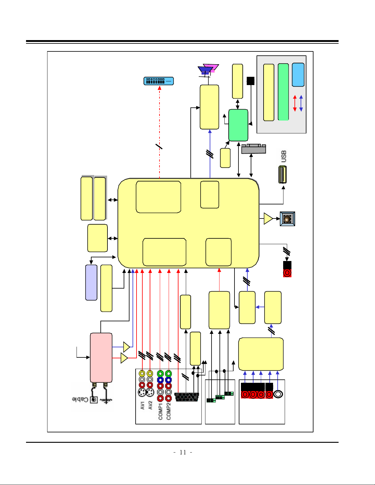
BLOCK DIAGRAM
Block Diagram - Overview
Audio L/R
Flash
(16MB)
DDR(64MB)
DDR(64MB)
74LVC14APW
TEA6420
(Audio
SW)
MC33078
(AMP)
CS5340
(A/D)
MTV416
(Micom)
NTP3000
(Digital AMP)
X-tal(54M)
TMDS341A
(3x1,S/W)
74F08D
EEPROM
AT/NT
Tuner
64Bit I/F
Reset
CVBS
CVBS/Y/C
Y/Cb/Cr
R/G/B
H/V Sync
RGB-PC
HDMI
0/1/2
COMP 1
COMP 2
AV 1
AV 2
RGB-PC
Audio L/R
I2S
MNT out
( L/R)
SPDIF OUT
I2S
RS-232C
Dead IC when Standby
Option
Alive IC when Standby
Video
Audio
Video
Front
End
Dual
HDMI
Rx
HD/SD
Video
Encoder
Audio
DSP
BCM3553
MCLK
MCLK
HDMI CEC
HDMI CEC
(To Micom)
To Micom
SDA
SCL
SIF
IF(AT)
Buffer
Single LVDS
Connector
Digital out (W)XGA
Local KEY
IR
Buffer Buffer
24C16
AGC CTL (From BCM)
USB2.0
I2S Audio Input
VSB/QAM/NTSC/SIF
DDR(128MB)
DDR(128MB)
Page 12

Copyright © 2007 LG Electronics. Inc. All right reserved.
Only for training and service purposes
LGE Internal Use Only
BLOCK DIAGRAM
Signal path for CVBS, Component, RGB
Comp1_Y
H Sync
V Sync
BCM3553
Comp1_Pb
Comp1_Pr
74F08D
Component 1
Input
Component 2
Input
RGB Input
RGB H_Sync
Side AV CVBS
Rear AV
Rear S_Video Y/C
Side S_Video
Y/C
CVBS
CVBS 2
L1/C1
CVBS 3
L2/C2
ANT/ Cable
TUNER
IF_P
IF_N
IF_P from TUNER for DTV
IF_N from TUNER for DTV
CVBS 1
EEPROM
FOR EDID
DDC SDA
DDC SCL
RGB V_Sync
LVDS_Tx
Out
Only for HD
Component_1 S/W
Component_2 S/W
Rear_CVBS_ S/W
RGB S/W
GPIO[0:6]
Comp2_Y
Comp2_Pb
Comp2_Pr
RGB_G
RGB_B
RGB_R
DDC SCL to Micom
for Download
LPF 6 Mhz
LPF 30Mhz
LPF 30Mhz
LPF 30Mhz
LPF 30Mhz
LPF 30Mhz
LPF 30Mhz
LPF 6 Mhz
LPF 6 Mhz
LPF 6 Mhz
DDC SDA to Micom
for Download
DVO Out[0:29]
Rear_S-Video_ S/W
Side_CVBS_ S/W
Side_S-Video_ S/W
31p
LVDS
Con.
31p
LVDS
Con.
Page 13

Copyright © 2007 LG Electronics. Inc. All right reserved.
Only for training and service purposes
LGE Internal Use Only
BLOCK DIAGRAM
Signal path for HDMI
BCM3553
TMDS0 RX0+/-
TMDS0 RX1+/-
TMDS0 RX2+/-
TMDS0 RXCLK+/-
DDC SDA0
DDC SCL0
EEPROM
For EDID
HDCP SDA
HDCP SCL
NDA
NCL
HDMI 0
HDMI 1
HDMi — CEC
+5V Power_0
Hot Plug Detect_0
TMDS1 RX0+/-
TMDS1 RX1+/-
TMDS1 RX2+/-
TMDS1 RXCLK+/-
DDC SDA1
DDC SCL1
EEPROM
For EDID
HDMi — CEC
+5V Power_1
Hot Plug Detect_1
LVDS_Tx
Out
HDMI 2
TMDS2 RX0+/-
TMDS2 RX1+/-
TMDS2 RX2+/-
TMDS2 RXCLK+/-
DDC SDA2
DDC SCL2
EEPROM
For EDID
HDMi — CEC
+5V Power_2
Hot Plug Detect_2
TMDS341A
TMDS0
INPUT
DDC SDA
DDC SCL
TMDS1
INPUT
TMDS2
INPUT
TMDS RX0+/-
TMDS RX1+/-
TMDS RX2+/-
TMDS RXCLK+/-
Hot Plug Detect_0
TMDS
Out
TMDS_Rx
Input
HDMi_Sel_0
HDMi_Sel_1
HDMi_Sel_2
Hot Plug Detect_1
Hot Plug Detect_2
+5V Power_0
+5V Power_1
+5V Power_2
GPIO[0:8]
Switch
Selection
DDC
INPUT
MTV416
MTV416
Micom
HDMi — CEC
Parallel connections with
HDMi 0,1,2
Only for HD 31P
LVDS
Con.
31P
LVDS
Con.
DVO Out[0:29]
EEPROM
for HDCP
EEPROM
for HDCP
DDC SDA0
DDC SCL0
DDC SDA1
DDC SCL1
DDC SDA2
DDC SCL2
DDC
OUT
Page 14

Copyright © 2007 LG Electronics. Inc. All right reserved.
Only for training and service purposes
LGE Internal Use Only
BLOCK DIAGRAM
AV1_Audio
AV2_Audio
MNT_Audio
HDMI
(PC/DTV)
Comp2_Audio
RGB_Audio
Comp1_Audio
[L1 / R1]
[L2 / R2]
[L3 / R3]
[L4 / R4]
[L5 / R5]
Switch
Switch
[Rout/Lout]
I2C SCL/SDA
Audio
Switch
[TEA6420]
AUDIO ADC
[CS5340]
I2S_CLK_IN/DATA_IN
/LR IN
(I2S_MCLK)
SPDIF OUT
Buffer
Buffer
OP AMP
[MC33078]
PWM MODULATOR/
POWER AMP
[NTP3000]
SIF IN
Broadcom
[BCM3553]
AUD_SPDIF
ANA L/R IN
ANA L/R
(MC33078)
ANA L/R
ANA L/R OUT
(CS5340)
BCM_MCLK
BCM_MCLK
I2S_CLK_IN
I2S_DATA_IN
I2S_LR_IN
RESET
RESET
I2S_CLK_OUT
I2S_DATA_OUT
I2S_LR_OUT
(NTP3000)
I2S_CLK_OUT/
DATA_OUT/
LRCH OUT
I2C SCL/SDA
OUT1A/B
OUT2A/B
SPK R
SPK L
MNT_L/R OUT
HDMI Rx
Built in
Internal
I2S/SPDIF
Convert
HDMI_TMDS 0/1/2/CLK
TUNER (ATSC/NTSC )
I2C SCL/SDA
Buffer
Buffer
SIF
IF_P
IF_N
AUD_LEFT/RIGHT P
HDMI_RX_DATA/CLK
ANA L/R OUT
BTSC
Decoder
MPEG2
Dolby
AUDIO
Processor
Signal path for AUDIO/ IF
SPDIF OUT(coaxial)
BCM_MCLK
IF AGC
CVBS
FRONT END
Page 15

Copyright © 2007 LG Electronics. Inc. All right reserved.
Only for training and service purposes
LGE Internal Use Only
BLOCK DIAGRAM
BCM3553
AUDIO S/W(TEA6420)
NTP3000
NVRAM
4.7K‰
5.0V
I2C_Channel 0
I2C_Channel 1
ATSC/NTSC Tuner
I2C_Channel 2
I2C_Channel 3
I2C0_5V
I2C1_5V
I2C2_2.5V
I2C2_3.3V
I2C3_3.3V
MTV416
4.7K‰
3.3VST
1K‰
3.3V
M62320
4.7K‰
5.0V
LM57(DS1621)
HDCP Key EEPROM
Address
0xC2
0x9A
0x74
0xA6
0x94
0x1C
0x54
0x??
0xD4
PDP MODULE
0x50
I2C MAP
CAT6431 Ready
(only S/W mode)
Page 16

Copyright © 2007 LG Electronics. Inc. All right reserved.
Only for training and service purposes
LGE Internal Use Only
BLOCK DIAGRAM
Block Diagram Power Sequence and Flow Diagram
P_+19V
P_+19V
IC501
NTP3000
(Sound IC)
BIAS
Speaker R/L
+12.0V
+12.0V
IC806
KA7809
IC500
TEA6420D
(Audio SW)
+9V
IC504
MC33078
(OP AMP)
Digital eye
LCD control B/D
IC901,902
KIA78R09F
(FAN REG)
FAN
FAN
REG IC BIAS Side power
Page 17

Copyright © 2007 LG Electronics. Inc. All right reserved.
Only for training and service purposes
LGE Internal Use Only
BLOCK DIAGRAM
Block Diagram Power Sequence and Flow Diagram
ST_5V
ST_5V
REG IC BIAS Side power
Local key/IR power
IC202
ICL3232
RS-232C RX/TX
IC404
AZ1117H-3.3
IC406
AT24C16AN
(EEPROM)
+3.3VST_MICOM
IC407
MTV416GMF
( micom )
BIAS
HDMI CEC
Inv/RL/live-on
3.3V->5V
BIAS
Page 18

Copyright © 2007 LG Electronics. Inc. All right reserved.
Only for training and service purposes
LGE Internal Use Only
BLOCK DIAGRAM
Block Diagram Power Sequence and Flow Diagram
+6.0V
+6.0V
REG IC BIAS Side power
IC800
PQ05DZ1U
TUNER
+5V_TU
Power_CTL_3.3V
Tuner SIF
IC801
PQ05DZ1U
+5.0V
IC102
CAT24WC
(HDCP KEY EEPROM)
BIAS
BCM PCI 단
BCM SCL/SDA0~1
BCM DS-AGC,AUD_VDD
BIAS
IC200
TPS2052
(USB power CTL
analog SW)
IC403
AT24C512W
(EEPROM NVRAM)
Inv/RL/live-on
3.3V->5V
IC502
CS5340
(Audio ADC)
입력단자 HPD
IC601/602/603/701
AT24C02BN
(EEPROM EDID)
EDID EEPROM
W/P
IC600
3:1HDMI SW
SCL/SDA
IC700
74F08D
(RGB HV AND GATE)
IC808
FMS6400
(Tuner video buffer)
IC900
M62320FP
(FAN driver)
IC903
LM75CIMX-3
(FAN 온도센서)
IC804
AZ1117H-3.3
IC802
AZ1117H-3.3
D3.3V_BCM
IC101
Flash MEM 32M
Reset SWBCM3553
IC401
74LVC14ADW
Reset 슈미트트리거
A3.3V_BCM
BCM3553
DAC/USB,AGC,HDMI
BOOT
STRAP
IC600
PICHDMI341
HDMI 3:1 SW
3.3V_TMDS_SW
Page 19

Copyright © 2007 LG Electronics. Inc. All right reserved.
Only for training and service purposes
LGE Internal Use Only
BLOCK DIAGRAM
Block Diagram Power Sequence and Flow Diagram
+3.3V
+3.3V
REG IC BIAS Side power
Power_CTL_2.6V_1.2V
IC803
SC1566I5M
D2.6V_BCM
BCM3553
IC300,301,302,303
DDR IC 전원
IC200,201
TPS2052BD
(USB analog SW)
IC501
NTP3000
(sound IC)
IC502
CS5340
(Audio ADC)
IC503
TC74VHC04FT
(coxial SPDIF IC)
JK501
SPDIF power
IC407
MTV416GMF
+3.3V detect signal
BIAS
LVDS Tuner CTR
IC304
5C25955TR
DDR Memory
DDR0_VTT
DDR0_REF
BCM3553
A2.6V_BCM
IC805
SC4519STRT
DC-DC converter
BCM3553
D1.2V_BCM
A1.2V_BCM
Power_CTL_2.6V_1.2V
IC807
AZ1117H-1.8
IC501
NTP3000
(sound IC)
+1.8V_NTP
Page 20

Copyright © 2007LG Electronics. Inc. All right reserved.
Only for training and service purposes
LGE Internal Use Only
EXPLODED VIEW
300
120
304
560
570
600
601
603
602
LV1
306
301
302
303
501
520
590
400
240
250
200
206
205
202
203
204
201
502
A2
900
901
Page 21

- 22 -
A1 MFL34797035 "Manual,Owners" PRINTING USER LA75C LG
A2 MKJ39927801 Remote Controller COMPLEX PA63E 50PC5D-U
A3 EAD36401701 Power Cord LP-31 + LS-13L LP-31 L
C103 0CE107SF6DC "Capacitor,AL,Chip" VMV107M016S0ANE010 100
C108 0CE107SF6DC "Capacitor,AL,Chip" VMV107M016S0ANE010 100
C241 0CE476WH6DC "Capacitor,AL,Chip" MVK8.0TP25VC47M 47uF 2
C242 0CE336WH6D8 "Capacitor,AL,Chip" MVK6.3TP25VC33M 33uF 2
C2601 0CH8106F691 "Capacitor,AL,Chip" MVK4.0TP16VC10M 10uF 2
C2665 0CE335WK6D8 "Capacitor,AL,Chip" MVK4.0TP50VC3.3M 3.3uF
C2666 0CE335WK6D8 "Capacitor,AL,Chip" MVK4.0TP50VC3.3M 3.3uF
C2667 0CE335WK6D8 "Capacitor,AL,Chip" MVK4.0TP50VC3.3M 3.3uF
C2668 0CE335WK6D8 "Capacitor,AL,Chip" MVK4.0TP50VC3.3M 3.3uF
C273 0CE476WH6DC "Capacitor,AL,Chip" MVK8.0TP25VC47M 47uF 2
C278 0CH8106F691 "Capacitor,AL,Chip" MVK4.0TP16VC10M 10uF 2
C300 0CE107WF6DC "Capacitor,AL,Chip" MVK6.3TP16VC100M 100uF
C320 0CE107WF6DC "Capacitor,AL,Chip" MVK6.3TP16VC100M 100uF
C338 0CE336WH6D8 "Capacitor,AL,Chip" MVK6.3TP25VC33M 33uF 2
C352 0CE107WF6DC "Capacitor,AL,Chip" MVK6.3TP16VC100M 100uF
C353 0CE107WF6DC "Capacitor,AL,Chip" MVK6.3TP16VC100M 100uF
C358 0CE107WF6DC "Capacitor,AL,Chip" MVK6.3TP16VC100M 100uF
C400 0CE106WFKDC "Capacitor,AL,Chip" MVK4.0TP16VC10M 10uF 2
C401 0CE106WFKDC "Capacitor,AL,Chip" MVK4.0TP16VC10M 10uF 2
C421 0CE106WFKDC "Capacitor,AL,Chip" MVK4.0TP16VC10M 10uF 2
C422 0CE476WF6DC "Capacitor,AL,Chip" MVK6.3TP16VC47M 47uF 2
C424 0CE476WF6DC "Capacitor,AL,Chip" MVK6.3TP16VC47M 47uF 2
C426 0CE106WFKDC "Capacitor,AL,Chip" MVK4.0TP16VC10M 10uF 2
C429 0CE107WF6DC "Capacitor,AL,Chip" MVK6.3TP16VC100M 100uF
C442 0CE476WF6DC "Capacitor,AL,Chip" MVK6.3TP16VC47M 47uF 2
C505 0CE106WFKDC "Capacitor,AL,Chip" MVK4.0TP16VC10M 10uF 2
C506 0CE106WFKDC "Capacitor,AL,Chip" MVK4.0TP16VC10M 10uF 2
C513 0CE337WJ6D8 "Capacitor,AL,Chip" MVK12.5TP35VC330M 330u
C519 0CE106WFKDC "Capacitor,AL,Chip" MVK4.0TP16VC10M 10uF 2
C527 0CE337WJ6D8 "Capacitor,AL,Chip" MVK12.5TP35VC330M 330u
C554 0CE107WF6DC "Capacitor,AL,Chip" MVK6.3TP16VC100M 100uF
C555 0CE226WF6DC "Capacitor,AL,Chip" MVK5.0TP16VC22M 22uF 2
C568 0CE226WF6DC "Capacitor,AL,Chip" MVK5.0TP16VC22M 22uF 2
C569 0CE226WF6DC "Capacitor,AL,Chip" MVK5.0TP16VC22M 22uF 2
C575 0CE107WF6DC "Capacitor,AL,Chip" MVK6.3TP16VC100M 100uF
C576 0CE226WF6DC "Capacitor,AL,Chip" MVK5.0TP16VC22M 22uF 2
C577 0CE226WF6DC "Capacitor,AL,Chip" MVK5.0TP16VC22M 22uF 2
C581 0CE105WK6DC "Capacitor,AL,Chip" MVK4.0TP50VC1M 1uF 20%
C583 0CE105WK6DC "Capacitor,AL,Chip" MVK4.0TP50VC1M 1uF 20%
C586 0CE105WK6DC "Capacitor,AL,Chip" MVK4.0TP50VC1M 1uF 20%
C587 0CE105WK6DC "Capacitor,AL,Chip" MVK4.0TP50VC1M 1uF 20%
C695 0CE107WF6DC "Capacitor,AL,Chip" MVK6.3TP16VC100M 100uF
C700 0CE105WK6DC "Capacitor,AL,Chip" MVK4.0TP50VC1M 1uF 20%
C701 0CE105WK6DC "Capacitor,AL,Chip" MVK4.0TP50VC1M 1uF 20%
C727 0CE476WF6DC "Capacitor,AL,Chip" MVK6.3TP16VC47M 47uF 2
C730 0CE105WK6DC "Capacitor,AL,Chip" MVK4.0TP50VC1M 1uF 20%
C731 0CE105WK6DC "Capacitor,AL,Chip" MVK4.0TP50VC1M 1uF 20%
C733 0CE107WH6DC "Capacitor,AL,Chip" MVK8.0TP25VC100M 100uF
C734 0CE105WK6DC "Capacitor,AL,Chip" MVK4.0TP50VC1M 1uF 20%
C735 0CE105WK6DC "Capacitor,AL,Chip" MVK4.0TP50VC1M 1uF 20%
C805 0CE476WF6DC "Capacitor,AL,Chip" MVK6.3TP16VC47M 47uF 2
C807 0CE107WF6DC "Capacitor,AL,Chip" MVK6.3TP16VC100M 100uF
C809 0CE107WF6DC "Capacitor,AL,Chip" MVK6.3TP16VC100M 100uF
C812 EAE30840201 "Capacitor,AL,Chip" 4SVPC330M 330uF 20% 4V
C813 EAE30840401 "Capacitor,AL,Chip" 25SVPD10M 10uF 20% 25V
C814 0CE476WF6DC "Capacitor,AL,Chip" MVK6.3TP16VC47M 47uF 2
C816 0CE476WF6DC "Capacitor,AL,Chip" MVK6.3TP16VC47M 47uF 2
C819 0CH8106F691 "Capacitor,AL,Chip" MVK4.0TP16VC10M 10uF 2
C824 0CE476WF6DC "Capacitor,AL,Chip" MVK6.3TP16VC47M 47uF 2
C828 0CE476WF6DC "Capacitor,AL,Chip" MVK6.3TP16VC47M 47uF 2
C829 0CE476WF6DC "Capacitor,AL,Chip" MVK6.3TP16VC47M 47uF 2
C831 0CE476WF6DC "Capacitor,AL,Chip" MVK6.3TP16VC47M 47uF 2
C837 0CE107WH6DC "Capacitor,AL,Chip" MVK8.0TP25VC100M 100uF
C841 EAE30840201 "Capacitor,AL,Chip" 4SVPC330M 330uF 20% 4V
C845 0CE105WK6DC "Capacitor,AL,Chip" MVK4.0TP50VC1M 1uF 20%
C846 0CE107WF6DC "Capacitor,AL,Chip" MVK6.3TP16VC100M 100uF
C851 0CE227WF6DC "Capacitor,AL,Chip" MVK8.0TP16VC220M 220uF
C854 0CE107WF6DC "Capacitor,AL,Chip" MVK6.3TP16VC100M 100uF
C860 0CE336WD6D8 "Capacitor,AL,Chip" RC1A336M05005VR 33uF 2
C862 0CE336WD6D8 "Capacitor,AL,Chip" RC1A336M05005VR 33uF 2
C863 0CE476WF6DC "Capacitor,AL,Chip" MVK6.3TP16VC47M 47uF 2
C865 0CE476WF6DC "Capacitor,AL,Chip" MVK6.3TP16VC47M 47uF 2
C867 0CE107WF6DC "Capacitor,AL,Chip" MVK6.3TP16VC100M 100uF
C868 0CE107WF6DC "Capacitor,AL,Chip" MVK6.3TP16VC100M 100uF
C9019 0CE106VF6DC "Capacitor,AL,Chip" VGV106M016S0ANB010 10u
C9020 0CE106VF6DC "Capacitor,AL,Chip" VGV106M016S0ANB010 10u
C9021 0CE106VF6DC "Capacitor,AL,Chip" VGV106M016S0ANB010 10u
C9023 0CE106VF6DC "Capacitor,AL,Chip" VGV106M016S0ANB010 10u
C907 0CE476WF6DC "Capacitor,AL,Chip" MVK6.3TP16VC47M 47uF 2
C914 0CE476WH6DC "Capacitor,AL,Chip" MVK8.0TP25VC47M 47uF 2
C100 0CK104BF56A "Capacitor,Ceramic,Chip" C1005X7R104KET 100nF 1
C101 0CH4471K416 "Capacitor,Ceramic,Chip" C2012C0G1H471JT 470pF
C101 0CK104BF56A "Capacitor,Ceramic,Chip" C1005X7R104KET 100nF 1
C102 0CH5101K416 "Capacitor,Ceramic,Chip" C2012C0G1H101JT 100pF
C102 0CK475CC94A "Capacitor,Ceramic,Chip" C1608Y5V0J475ZT 4.7uF
C103 0CK104BF56A "Capacitor,Ceramic,Chip" C1005X7R104KET 100nF 1
C104 0CH4471K416 "Capacitor,Ceramic,Chip" C2012C0G1H471JT 470pF
C105 0CH4471K416 "Capacitor,Ceramic,Chip" C2012C0G1H471JT 470pF
C105 0CH5101K416 "Capacitor,Ceramic,Chip" C2012C0G1H101JT 100pF
C105 0CK475CC94A "Capacitor,Ceramic,Chip" C1608Y5V0J475ZT 4.7uF
C106 0CH5101K416 "Capacitor,Ceramic,Chip" C2012C0G1H101JT 100pF
C106 0CK104BF56A "Capacitor,Ceramic,Chip" C1005X7R104KET 100nF 1
C108 0CK104BF56A "Capacitor,Ceramic,Chip" C1005X7R104KET 100nF 1
LOC. NO. PART NO. DESCRIPTION / SPECIFICATION LOC. NO. PART NO. DESCRIPTION / SPECIFICATION
REPLACEMENT PARTS LIST
DATE: 2007. 10. 24.
CAPACITORs
ACCESSORY
Page 22

- 23 -
C109 0CK103BH56A "Capacitor,Ceramic,Chip" C1005X7R1E103KT- 10nF
C110 0CK104BF56A "Capacitor,Ceramic,Chip" C1005X7R104KET 100nF 1
C111 0CK104BF56A "Capacitor,Ceramic,Chip" C1005X7R104KET 100nF 1
C112 0CK104BF56A "Capacitor,Ceramic,Chip" C1005X7R104KET 100nF 1
C113 0CK104BF56A "Capacitor,Ceramic,Chip" C1005X7R104KET 100nF 1
C114 0CK104BF56A "Capacitor,Ceramic,Chip" C1005X7R104KET 100nF 1
C123 0CK104BF56A "Capacitor,Ceramic,Chip" C1005X7R104KET 100nF 1
C124 0CK104BF56A "Capacitor,Ceramic,Chip" C1005X7R104KET 100nF 1
C125 0CK104BF56A "Capacitor,Ceramic,Chip" C1005X7R104KET 100nF 1
C126 0CK475CC94A "Capacitor,Ceramic,Chip" C1608Y5V0J475ZT 4.7uF
C127 0CK104BF56A "Capacitor,Ceramic,Chip" C1005X7R104KET 100nF 1
C128 0CK104BF56A "Capacitor,Ceramic,Chip" C1005X7R104KET 100nF 1
C129 0CK104BF56A "Capacitor,Ceramic,Chip" C1005X7R104KET 100nF 1
C130 0CK104BF56A "Capacitor,Ceramic,Chip" C1005X7R104KET 100nF 1
C131 0CK104BF56A "Capacitor,Ceramic,Chip" C1005X7R104KET 100nF 1
C132 0CK104BF56A "Capacitor,Ceramic,Chip" C1005X7R104KET 100nF 1
C200 0CK475DD57A "Capacitor,Ceramic,Chip" C2012X5R1A475KT 4.7uF
C201 0CK104BF56A "Capacitor,Ceramic,Chip" C1005X7R104KET 100nF 1
C202 0CK104BF56A "Capacitor,Ceramic,Chip" C1005X7R104KET 100nF 1
C203 0CK104BF56A "Capacitor,Ceramic,Chip" C1005X7R104KET 100nF 1
C204 0CK475CC94A "Capacitor,Ceramic,Chip" C1608Y5V0J475ZT 4.7uF
C205 0CK104BF56A "Capacitor,Ceramic,Chip" C1005X7R104KET 100nF 1
C206 0CK475CC94A "Capacitor,Ceramic,Chip" C1608Y5V0J475ZT 4.7uF
C207 0CK101BK4EA "Capacitor,Ceramic,Chip" C1005C0G1H101JT 100pF
C208 0CK104BF56A "Capacitor,Ceramic,Chip" C1005X7R104KET 100nF 1
C209 0CK475CC94A "Capacitor,Ceramic,Chip" C1608Y5V0J475ZT 4.7uF
C210 0CK104BF56A "Capacitor,Ceramic,Chip" C1005X7R104KET 100nF 1
C211 0CK475CC94A "Capacitor,Ceramic,Chip" C1608Y5V0J475ZT 4.7uF
C212 0CK104BF56A "Capacitor,Ceramic,Chip" C1005X7R104KET 100nF 1
C213 0CK103BH56A "Capacitor,Ceramic,Chip" C1005X7R1E103KT- 10nF
C214 0CK102BK56A "Capacitor,Ceramic,Chip" 0402B102K500CT 1nF 10%
C215 0CK104BF56A "Capacitor,Ceramic,Chip" C1005X7R104KET 100nF 1
C216 0CK103BH56A "Capacitor,Ceramic,Chip" C1005X7R1E103KT- 10nF
C217 0CK102BK56A "Capacitor,Ceramic,Chip" 0402B102K500CT 1nF 10%
C218 0CK104BF56A "Capacitor,Ceramic,Chip" C1005X7R104KET 100nF 1
C219 0CK104BF56A "Capacitor,Ceramic,Chip" C1005X7R104KET 100nF 1
C220 EAE33970001 "Capacitor,Ceramic,Chip" CS1005X5R105K6R3NR 1uF
C221 EAE33970001 "Capacitor,Ceramic,Chip" CS1005X5R105K6R3NR 1uF
C222 EAE32479401 "Capacitor,Ceramic,Chip" CH1005CG471J500NR 470p
C223 EAE32479401 "Capacitor,Ceramic,Chip" CH1005CG471J500NR 470p
C224 0CK103BH56A "Capacitor,Ceramic,Chip" C1005X7R1E103KT- 10nF
C227 0CK475CC94A "Capacitor,Ceramic,Chip" C1608Y5V0J475ZT 4.7uF
C228 0CK105CD56A "Capacitor,Ceramic,Chip" C1608X7R1A105KT 1uF 10
C229 0CC120CK41A "Capacitor,Ceramic,Chip" C1608C0G1H120JT 12pF 5
C230 0CC120CK41A "Capacitor,Ceramic,Chip" C1608C0G1H120JT 12pF 5
C232 0CZZB00035A "Capacitor,Ceramic,Chip" GRM1555C1H330J 33pF 5%
C234 0CK104BF56A "Capacitor,Ceramic,Chip" C1005X7R104KET 100nF 1
C235 0CK475CC94A "Capacitor,Ceramic,Chip" C1608Y5V0J475ZT 4.7uF
C236 0CK102BK56A "Capacitor,Ceramic,Chip" 0402B102K500CT 1nF 10%
C237 0CK103BH56A "Capacitor,Ceramic,Chip" C1005X7R1E103KT- 10nF
C238 0CK104BF56A "Capacitor,Ceramic,Chip" C1005X7R104KET 100nF 1
C239 0CK106DC67A "Capacitor,Ceramic,Chip" JMK212JB106MG-T 10uF 2
C240 0CK106DC67A "Capacitor,Ceramic,Chip" JMK212JB106MG-T 10uF 2
C243 0CK102BK56A "Capacitor,Ceramic,Chip" 0402B102K500CT 1nF 10%
C244 0CK103BH56A "Capacitor,Ceramic,Chip" C1005X7R1E103KT- 10nF
C245 0CK104BF56A "Capacitor,Ceramic,Chip" C1005X7R104KET 100nF 1
C246 0CK475CC94A "Capacitor,Ceramic,Chip" C1608Y5V0J475ZT 4.7uF
C247 0CK102BK56A "Capacitor,Ceramic,Chip" 0402B102K500CT 1nF 10%
C248 0CK103BH56A "Capacitor,Ceramic,Chip" C1005X7R1E103KT- 10nF
C249 0CK104BF56A "Capacitor,Ceramic,Chip" C1005X7R104KET 100nF 1
C250 0CK475CC94A "Capacitor,Ceramic,Chip" C1608Y5V0J475ZT 4.7uF
C251 0CK102BK56A "Capacitor,Ceramic,Chip" 0402B102K500CT 1nF 10%
C252 0CK103BH56A "Capacitor,Ceramic,Chip" C1005X7R1E103KT- 10nF
C253 0CK475CC94A "Capacitor,Ceramic,Chip" C1608Y5V0J475ZT 4.7uF
C254 0CK102BK56A "Capacitor,Ceramic,Chip" 0402B102K500CT 1nF 10%
C255 0CK103BH56A "Capacitor,Ceramic,Chip" C1005X7R1E103KT- 10nF
C256 0CK104BF56A "Capacitor,Ceramic,Chip" C1005X7R104KET 100nF 1
C257 0CK475CC94A "Capacitor,Ceramic,Chip" C1608Y5V0J475ZT 4.7uF
C258 0CK102BK56A "Capacitor,Ceramic,Chip" 0402B102K500CT 1nF 10%
C259 0CK103BH56A "Capacitor,Ceramic,Chip" C1005X7R1E103KT- 10nF
C260 0CK104BF56A "Capacitor,Ceramic,Chip" C1005X7R104KET 100nF 1
C2600 0CK104BF56A "Capacitor,Ceramic,Chip" C1005X7R104KET 100nF 1
C2602 0CK104BF56A "Capacitor,Ceramic,Chip" C1005X7R104KET 100nF 1
C2603 0CK104BF56A "Capacitor,Ceramic,Chip" C1005X7R104KET 100nF 1
C2604 0CK104BF56A "Capacitor,Ceramic,Chip" C1005X7R104KET 100nF 1
C261 0CK106DC67A "Capacitor,Ceramic,Chip" JMK212JB106MG-T 10uF 2
C262 0CK102BK56A "Capacitor,Ceramic,Chip" 0402B102K500CT 1nF 10%
C263 0CK103BH56A "Capacitor,Ceramic,Chip" C1005X7R1E103KT- 10nF
C264 0CK104BF56A "Capacitor,Ceramic,Chip" C1005X7R104KET 100nF 1
C265 0CK475CC94A "Capacitor,Ceramic,Chip" C1608Y5V0J475ZT 4.7uF
C266 0CK102BK56A "Capacitor,Ceramic,Chip" 0402B102K500CT 1nF 10%
C2662 0CK104BF56A "Capacitor,Ceramic,Chip" C1005X7R104KET 100nF 1
C2663 0CC100BKF1A "Capacitor,Ceramic,Chip" 0402N100J500LT 10pF 5%
C2664 0CK106CC67A "Capacitor,Ceramic,Chip" C1608X5R0J106MT 10uF 2
C267 0CK103BH56A "Capacitor,Ceramic,Chip" C1005X7R1E103KT- 10nF
C268 0CK104BF56A "Capacitor,Ceramic,Chip" C1005X7R104KET 100nF 1
C269 0CK102BK56A "Capacitor,Ceramic,Chip" 0402B102K500CT 1nF 10%
C270 0CK103BH56A "Capacitor,Ceramic,Chip" C1005X7R1E103KT- 10nF
C271 0CK104BF56A "Capacitor,Ceramic,Chip" C1005X7R104KET 100nF 1
C272 0CK106DC67A "Capacitor,Ceramic,Chip" JMK212JB106MG-T 10uF 2
C274 0CK104BF56A "Capacitor,Ceramic,Chip" C1005X7R104KET 100nF 1
C275 0CK103BH56A "Capacitor,Ceramic,Chip" C1005X7R1E103KT- 10nF
C276 0CK475CC94A "Capacitor,Ceramic,Chip" C1608Y5V0J475ZT 4.7uF
C279 0CK104BF56A "Capacitor,Ceramic,Chip" C1005X7R104KET 100nF 1
C280 0CK104BF56A "Capacitor,Ceramic,Chip" C1005X7R104KET 100nF 1
C281 0CK104BF56A "Capacitor,Ceramic,Chip" C1005X7R104KET 100nF 1
C282 0CK105CD56A "Capacitor,Ceramic,Chip" C1608X7R1A105KT 1uF 10
C283 0CK104BF56A "Capacitor,Ceramic,Chip" C1005X7R104KET 100nF 1
C284 0CK104BF56A "Capacitor,Ceramic,Chip" C1005X7R104KET 100nF 1
C285 0CK104BF56A "Capacitor,Ceramic,Chip" C1005X7R104KET 100nF 1
C286 0CK104BF56A "Capacitor,Ceramic,Chip" C1005X7R104KET 100nF 1
C287 0CK104BF56A "Capacitor,Ceramic,Chip" C1005X7R104KET 100nF 1
C288 0CK104BF56A "Capacitor,Ceramic,Chip" C1005X7R104KET 100nF 1
C289 0CK104BF56A "Capacitor,Ceramic,Chip" C1005X7R104KET 100nF 1
C290 0CK104BF56A "Capacitor,Ceramic,Chip" C1005X7R104KET 100nF 1
C2900 0CC100BKF1A "Capacitor,Ceramic,Chip" 0402N100J500LT 10pF 5%
C2901 0CC100BKF1A "Capacitor,Ceramic,Chip" 0402N100J500LT 10pF 5%
C291 0CK104BF56A "Capacitor,Ceramic,Chip" C1005X7R104KET 100nF 1
C292 0CK104BF56A "Capacitor,Ceramic,Chip" C1005X7R104KET 100nF 1
C295 0CK104BF56A "Capacitor,Ceramic,Chip" C1005X7R104KET 100nF 1
LOC. NO. PART NO. DESCRIPTION / SPECIFICATION LOC. NO. PART NO. DESCRIPTION / SPECIFICATION
Page 23

- 24 -
C3001 0CK104BF56A "Capacitor,Ceramic,Chip" C1005X7R104KET 100nF 1
C3002 0CK104BF56A "Capacitor,Ceramic,Chip" C1005X7R104KET 100nF 1
C301 0CK104BF56A "Capacitor,Ceramic,Chip" C1005X7R104KET 100nF 1
C302 0CK103BH56A "Capacitor,Ceramic,Chip" C1005X7R1E103KT- 10nF
C303 EAE32166101 "Capacitor,Ceramic,Chip" CS1005XR473K250CR 0.04
C304 0CK272BKF6A "Capacitor,Ceramic,Chip" 0402B272J500CT 2.7nF 5
C305 EAE32479401 "Capacitor,Ceramic,Chip" CH1005CG471J500NR 470p
C312 0CK104BF56A "Capacitor,Ceramic,Chip" C1005X7R104KET 100nF 1
C313 EAE32479401 "Capacitor,Ceramic,Chip" CH1005CG471J500NR 470p
C316 0CK104BF56A "Capacitor,Ceramic,Chip" C1005X7R104KET 100nF 1
C317 EAE32479401 "Capacitor,Ceramic,Chip" CH1005CG471J500NR 470p
C321 0CK104BF56A "Capacitor,Ceramic,Chip" C1005X7R104KET 100nF 1
C322 0CK103BH56A "Capacitor,Ceramic,Chip" C1005X7R1E103KT- 10nF
C323 EAE32166101 "Capacitor,Ceramic,Chip" CS1005XR473K250CR 0.04
C324 0CK272BKF6A "Capacitor,Ceramic,Chip" 0402B272J500CT 2.7nF 5
C325 EAE32479401 "Capacitor,Ceramic,Chip" CH1005CG471J500NR 470p
C332 0CK104BF56A "Capacitor,Ceramic,Chip" C1005X7R104KET 100nF 1
C333 0CK104BF56A "Capacitor,Ceramic,Chip" C1005X7R104KET 100nF 1
C334 EAE33970001 "Capacitor,Ceramic,Chip" CS1005X5R105K6R3NR 1uF
C335 EAE33970001 "Capacitor,Ceramic,Chip" CS1005X5R105K6R3NR 1uF
C336 EAE32479401 "Capacitor,Ceramic,Chip" CH1005CG471J500NR 470p
C337 EAE32479401 "Capacitor,Ceramic,Chip" CH1005CG471J500NR 470p
C339 0CK106DC67A "Capacitor,Ceramic,Chip" JMK212JB106MG-T 10uF 2
C340 0CK104BF56A "Capacitor,Ceramic,Chip" C1005X7R104KET 100nF 1
C341 0CK103BH56A "Capacitor,Ceramic,Chip" C1005X7R1E103KT- 10nF
C342 0CK102BK56A "Capacitor,Ceramic,Chip" 0402B102K500CT 1nF 10%
C344 0CK103BH56A "Capacitor,Ceramic,Chip" C1005X7R1E103KT- 10nF
C345 0CK102BK56A "Capacitor,Ceramic,Chip" 0402B102K500CT 1nF 10%
C346 0CK104BF56A "Capacitor,Ceramic,Chip" C1005X7R104KET 100nF 1
C347 0CK103BH56A "Capacitor,Ceramic,Chip" C1005X7R1E103KT- 10nF
C348 0CK102BK56A "Capacitor,Ceramic,Chip" 0402B102K500CT 1nF 10%
C349 0CK104BF56A "Capacitor,Ceramic,Chip" C1005X7R104KET 100nF 1
C350 0CK103BH56A "Capacitor,Ceramic,Chip" C1005X7R1E103KT- 10nF
C351 0CK102BK56A "Capacitor,Ceramic,Chip" 0402B102K500CT 1nF 10%
C354 0CK103CK56A "Capacitor,Ceramic,Chip" 0603B103K500CT 10nF 10
C355 0CK104BF56A "Capacitor,Ceramic,Chip" C1005X7R104KET 100nF 1
C356 0CK103CK56A "Capacitor,Ceramic,Chip" 0603B103K500CT 10nF 10
C357 0CK225DD66A "Capacitor,Ceramic,Chip" LMK212JB225MG-T 2.2uF
C359 0CK105CD56A "Capacitor,Ceramic,Chip" C1608X7R1A105KT 1uF 10
C360 0CK103CK56A "Capacitor,Ceramic,Chip" 0603B103K500CT 10nF 10
C361 0CK104BF56A "Capacitor,Ceramic,Chip" C1005X7R104KET 100nF 1
C362 0CK104BF56A "Capacitor,Ceramic,Chip" C1005X7R104KET 100nF 1
C368 0CK102BK56A "Capacitor,Ceramic,Chip" 0402B102K500CT 1nF 10%
C369 0CK102BK56A "Capacitor,Ceramic,Chip" 0402B102K500CT 1nF 10%
C370 0CK102BK56A "Capacitor,Ceramic,Chip" 0402B102K500CT 1nF 10%
C371 0CK102BK56A "Capacitor,Ceramic,Chip" 0402B102K500CT 1nF 10%
C372 0CK102BK56A "Capacitor,Ceramic,Chip" 0402B102K500CT 1nF 10%
C373 0CK102BK56A "Capacitor,Ceramic,Chip" 0402B102K500CT 1nF 10%
C374 EAE32479401 "Capacitor,Ceramic,Chip" CH1005CG471J500NR 470p
C375 EAE32479401 "Capacitor,Ceramic,Chip" CH1005CG471J500NR 470p
C376 0CK103BH56A "Capacitor,Ceramic,Chip" C1005X7R1E103KT- 10nF
C378 0CK103BH56A "Capacitor,Ceramic,Chip" C1005X7R1E103KT- 10nF
C380 0CK103BH56A "Capacitor,Ceramic,Chip" C1005X7R1E103KT- 10nF
C381 0CK103BH56A "Capacitor,Ceramic,Chip" C1005X7R1E103KT- 10nF
C382 0CK103BH56A "Capacitor,Ceramic,Chip" C1005X7R1E103KT- 10nF
C383 0CK103BH56A "Capacitor,Ceramic,Chip" C1005X7R1E103KT- 10nF
C384 0CK103BH56A "Capacitor,Ceramic,Chip" C1005X7R1E103KT- 10nF
C385 0CK103BH56A "Capacitor,Ceramic,Chip" C1005X7R1E103KT- 10nF
C386 0CK103BH56A "Capacitor,Ceramic,Chip" C1005X7R1E103KT- 10nF
C387 EAE32479401 "Capacitor,Ceramic,Chip" CH1005CG471J500NR 470p
C388 EAE32479401 "Capacitor,Ceramic,Chip" CH1005CG471J500NR 470p
C394 0CK103BH56A "Capacitor,Ceramic,Chip" C1005X7R1E103KT- 10nF
C396 0CK103BH56A "Capacitor,Ceramic,Chip" C1005X7R1E103KT- 10nF
C397 0CK475CC94A "Capacitor,Ceramic,Chip" C1608Y5V0J475ZT 4.7uF
C402 0CK104BF56A "Capacitor,Ceramic,Chip" C1005X7R104KET 100nF 1
C403 0CK104BF56A "Capacitor,Ceramic,Chip" C1005X7R104KET 100nF 1
C404 0CK104CF56A "Capacitor,Ceramic,Chip" 0603B104K160CT 100nF 1
C405 0CK104CF56A "Capacitor,Ceramic,Chip" 0603B104K160CT 100nF 1
C406 0CK104BF56A "Capacitor,Ceramic,Chip" C1005X7R104KET 100nF 1
C407 0CK104CF56A "Capacitor,Ceramic,Chip" 0603B104K160CT 100nF 1
C408 0CK104BF56A "Capacitor,Ceramic,Chip" C1005X7R104KET 100nF 1
C409 0CC221BKFAA "Capacitor,Ceramic,Chip" C1005C0G1H221JT 220pF
C410 0CC221BKFAA "Capacitor,Ceramic,Chip" C1005C0G1H221JT 220pF
C411 0CK104BF56A "Capacitor,Ceramic,Chip" C1005X7R104KET 100nF 1
C412 0CK104BF56A "Capacitor,Ceramic,Chip" C1005X7R104KET 100nF 1
C413 0CK104BF56A "Capacitor,Ceramic,Chip" C1005X7R104KET 100nF 1
C414 0CK104BF56A "Capacitor,Ceramic,Chip" C1005X7R104KET 100nF 1
C415 0CK104BF56A "Capacitor,Ceramic,Chip" C1005X7R104KET 100nF 1
C416 0CK104BF56A "Capacitor,Ceramic,Chip" C1005X7R104KET 100nF 1
C419 0CK104BF56A "Capacitor,Ceramic,Chip" C1005X7R104KET 100nF 1
C420 0CK104BF56A "Capacitor,Ceramic,Chip" C1005X7R104KET 100nF 1
C423 0CK104BF56A "Capacitor,Ceramic,Chip" C1005X7R104KET 100nF 1
C425 0CK104BF56A "Capacitor,Ceramic,Chip" C1005X7R104KET 100nF 1
C427 0CK104BF56A "Capacitor,Ceramic,Chip" C1005X7R104KET 100nF 1
C428 0CK104BF56A "Capacitor,Ceramic,Chip" C1005X7R104KET 100nF 1
C430 0CK104BF56A "Capacitor,Ceramic,Chip" C1005X7R104KET 100nF 1
C431 0CK104BF56A "Capacitor,Ceramic,Chip" C1005X7R104KET 100nF 1
C433 0CK104BF56A "Capacitor,Ceramic,Chip" C1005X7R104KET 100nF 1
C434 0CK104BF56A "Capacitor,Ceramic,Chip" C1005X7R104KET 100nF 1
C435 0CH5220K618 "Capacitor,Ceramic,Chip" 0402N220M500LT 22pF 5%
C436 0CH5220K618 "Capacitor,Ceramic,Chip" 0402N220M500LT 22pF 5%
C437 0CK104BF56A "Capacitor,Ceramic,Chip" C1005X7R104KET 100nF 1
C438 0CK104BF56A "Capacitor,Ceramic,Chip" C1005X7R104KET 100nF 1
C439 0CK104BF56A "Capacitor,Ceramic,Chip" C1005X7R104KET 100nF 1
C440 0CK104BF56A "Capacitor,Ceramic,Chip" C1005X7R104KET 100nF 1
C441 0CK104BF56A "Capacitor,Ceramic,Chip" C1005X7R104KET 100nF 1
C500 0CK101BK4EA "Capacitor,Ceramic,Chip" C1005C0G1H101JT 100pF
C501 0CK102BK56A "Capacitor,Ceramic,Chip" 0402B102K500CT 1nF 10%
C503 0CK104BF56A "Capacitor,Ceramic,Chip" C1005X7R104KET 100nF 1
C504 0CK104BF56A "Capacitor,Ceramic,Chip" C1005X7R104KET 100nF 1
C507 0CK104BF56A "Capacitor,Ceramic,Chip" C1005X7R104KET 100nF 1
C508 0CZZB00035A "Capacitor,Ceramic,Chip" GRM1555C1H330J 33pF 5%
C509 0CK105CD56A "Capacitor,Ceramic,Chip" C1608X7R1A105KT 1uF 10
C510 0CZZB00035A "Capacitor,Ceramic,Chip" GRM1555C1H330J 33pF 5%
C511 0CZZB00035A "Capacitor,Ceramic,Chip" GRM1555C1H330J 33pF 5%
C512 0CK223CK56A "Capacitor,Ceramic,Chip" UMK107JB223KA-T 22nF 1
C514 0CK104CK56A "Capacitor,Ceramic,Chip" 0603B104K500CT 100nF 1
C515 0CK223CK56A "Capacitor,Ceramic,Chip" UMK107JB223KA-T 22nF 1
C516 0CK104BF56A "Capacitor,Ceramic,Chip" C1005X7R104KET 100nF 1
C517 0CK104CK56A "Capacitor,Ceramic,Chip" 0603B104K500CT 100nF 1
LOC. NO. PART NO. DESCRIPTION / SPECIFICATION LOC. NO. PART NO. DESCRIPTION / SPECIFICATION
Page 24

- 25 -
C518 0CK104CK56A "Capacitor,Ceramic,Chip" 0603B104K500CT 100nF 1
C520 0CK103CK56A "Capacitor,Ceramic,Chip" 0603B103K500CT 10nF 10
C521 0CK105CD56A "Capacitor,Ceramic,Chip" C1608X7R1A105KT 1uF 10
C522 0CK105CD56A "Capacitor,Ceramic,Chip" C1608X7R1A105KT 1uF 10
C523 0CK223CK56A "Capacitor,Ceramic,Chip" UMK107JB223KA-T 22nF 1
C524 0CK223CK56A "Capacitor,Ceramic,Chip" UMK107JB223KA-T 22nF 1
C525 0CK105CD56A "Capacitor,Ceramic,Chip" C1608X7R1A105KT 1uF 10
C526 0CK104CK56A "Capacitor,Ceramic,Chip" 0603B104K500CT 100nF 1
C528 0CK104CK56A "Capacitor,Ceramic,Chip" 0603B104K500CT 100nF 1
C529 0CK104CK56A "Capacitor,Ceramic,Chip" 0603B104K500CT 100nF 1
C530 0CK103CK56A "Capacitor,Ceramic,Chip" 0603B103K500CT 10nF 10
C535 0CK102CK56A "Capacitor,Ceramic,Chip" 0603B102K500CT 1nF 10%
C536 0CK102CK56A "Capacitor,Ceramic,Chip" 0603B102K500CT 1nF 10%
C537 0CK102CK56A "Capacitor,Ceramic,Chip" 0603B102K500CT 1nF 10%
C538 0CK102CK56A "Capacitor,Ceramic,Chip" 0603B102K500CT 1nF 10%
C539 0CK104CK56A "Capacitor,Ceramic,Chip" 0603B104K500CT 100nF 1
C540 0CK104CK56A "Capacitor,Ceramic,Chip" 0603B104K500CT 100nF 1
C541 0CK104CK56A "Capacitor,Ceramic,Chip" 0603B104K500CT 100nF 1
C542 0CK104CK56A "Capacitor,Ceramic,Chip" 0603B104K500CT 100nF 1
C543 0CK474DK56A "Capacitor,Ceramic,Chip" UMK212BJ474KG-T 470nF
C544 0CK474DK56A "Capacitor,Ceramic,Chip" UMK212BJ474KG-T 470nF
C545 0CK103CK56A "Capacitor,Ceramic,Chip" 0603B103K500CT 10nF 10
C546 0CK103CK56A "Capacitor,Ceramic,Chip" 0603B103K500CT 10nF 10
C547 0CK103CK56A "Capacitor,Ceramic,Chip" 0603B103K500CT 10nF 10
C548 0CK103CK56A "Capacitor,Ceramic,Chip" 0603B103K500CT 10nF 10
C556 0CK103CK56A "Capacitor,Ceramic,Chip" 0603B103K500CT 10nF 10
C566 0CK104BF56A "Capacitor,Ceramic,Chip" C1005X7R104KET 100nF 1
C567 0CK103CK56A "Capacitor,Ceramic,Chip" 0603B103K500CT 10nF 10
C570 0CH5470K618 "Capacitor,Ceramic,Chip" 0402N470M500LT 47pF 5%
C571 0CK104CK56A "Capacitor,Ceramic,Chip" 0603B104K500CT 100nF 1
C572 0CK104CK56A "Capacitor,Ceramic,Chip" 0603B104K500CT 100nF 1
C573 0CK104CK56A "Capacitor,Ceramic,Chip" 0603B104K500CT 100nF 1
C574 0CH5470K618 "Capacitor,Ceramic,Chip" 0402N470M500LT 47pF 5%
C578 0CK103CK56A "Capacitor,Ceramic,Chip" 0603B103K500CT 10nF 10
C579 0CK104BF56A "Capacitor,Ceramic,Chip" C1005X7R104KET 100nF 1
C580 0CK104BF56A "Capacitor,Ceramic,Chip" C1005X7R104KET 100nF 1
C582 0CK104BF56A "Capacitor,Ceramic,Chip" C1005X7R104KET 100nF 1
C584 0CK104BF56A "Capacitor,Ceramic,Chip" C1005X7R104KET 100nF 1
C585 0CK104BF56A "Capacitor,Ceramic,Chip" C1005X7R104KET 100nF 1
C588 0CK104BF56A "Capacitor,Ceramic,Chip" C1005X7R104KET 100nF 1
C589 0CK104BF56A "Capacitor,Ceramic,Chip" C1005X7R104KET 100nF 1
C590 0CK104BF56A "Capacitor,Ceramic,Chip" C1005X7R104KET 100nF 1
C591 0CK104BF56A "Capacitor,Ceramic,Chip" C1005X7R104KET 100nF 1
C592 0CK104BF56A "Capacitor,Ceramic,Chip" C1005X7R104KET 100nF 1
C600 0CK103BH56A "Capacitor,Ceramic,Chip" C1005X7R1E103KT- 10nF
C601 0CK103BH56A "Capacitor,Ceramic,Chip" C1005X7R1E103KT- 10nF
C602 0CK103BH56A "Capacitor,Ceramic,Chip" C1005X7R1E103KT- 10nF
C603 0CK103BH56A "Capacitor,Ceramic,Chip" C1005X7R1E103KT- 10nF
C604 0CK103BH56A "Capacitor,Ceramic,Chip" C1005X7R1E103KT- 10nF
C605 0CK103BH56A "Capacitor,Ceramic,Chip" C1005X7R1E103KT- 10nF
C606 0CK103BH56A "Capacitor,Ceramic,Chip" C1005X7R1E103KT- 10nF
C607 0CK103BH56A "Capacitor,Ceramic,Chip" C1005X7R1E103KT- 10nF
C608 0CK103BH56A "Capacitor,Ceramic,Chip" C1005X7R1E103KT- 10nF
C609 0CK103BH56A "Capacitor,Ceramic,Chip" C1005X7R1E103KT- 10nF
C610 0CK103BH56A "Capacitor,Ceramic,Chip" C1005X7R1E103KT- 10nF
C611 0CK103BH56A "Capacitor,Ceramic,Chip" C1005X7R1E103KT- 10nF
C618 0CK104BF56A "Capacitor,Ceramic,Chip" C1005X7R104KET 100nF 1
C620 0CK104BF56A "Capacitor,Ceramic,Chip" C1005X7R104KET 100nF 1
C621 0CK475CC94A "Capacitor,Ceramic,Chip" C1608Y5V0J475ZT 4.7uF
C622 0CK475CC94A "Capacitor,Ceramic,Chip" C1608Y5V0J475ZT 4.7uF
C623 0CK475CC94A "Capacitor,Ceramic,Chip" C1608Y5V0J475ZT 4.7uF
C625 0CK104BF56A "Capacitor,Ceramic,Chip" C1005X7R104KET 100nF 1
C626 0CK104BF56A "Capacitor,Ceramic,Chip" C1005X7R104KET 100nF 1
C627 0CK104BF56A "Capacitor,Ceramic,Chip" C1005X7R104KET 100nF 1
C628 0CK104BF56A "Capacitor,Ceramic,Chip" C1005X7R104KET 100nF 1
C629 0CK104BF56A "Capacitor,Ceramic,Chip" C1005X7R104KET 100nF 1
C630 0CK104BF56A "Capacitor,Ceramic,Chip" C1005X7R104KET 100nF 1
C631 0CK104BF56A "Capacitor,Ceramic,Chip" C1005X7R104KET 100nF 1
C632 0CK104BF56A "Capacitor,Ceramic,Chip" C1005X7R104KET 100nF 1
C633 0CK104BF56A "Capacitor,Ceramic,Chip" C1005X7R104KET 100nF 1
C634 0CK104BF56A "Capacitor,Ceramic,Chip" C1005X7R104KET 100nF 1
C635 0CK104BF56A "Capacitor,Ceramic,Chip" C1005X7R104KET 100nF 1
C636 0CK104BF56A "Capacitor,Ceramic,Chip" C1005X7R104KET 100nF 1
C637 0CK104BF56A "Capacitor,Ceramic,Chip" C1005X7R104KET 100nF 1
C638 0CK104BF56A "Capacitor,Ceramic,Chip" C1005X7R104KET 100nF 1
C639 0CK104BF56A "Capacitor,Ceramic,Chip" C1005X7R104KET 100nF 1
C640 0CK104BF56A "Capacitor,Ceramic,Chip" C1005X7R104KET 100nF 1
C641 0CK104BF56A "Capacitor,Ceramic,Chip" C1005X7R104KET 100nF 1
C642 0CK104BF56A "Capacitor,Ceramic,Chip" C1005X7R104KET 100nF 1
C644 0CK104BF56A "Capacitor,Ceramic,Chip" C1005X7R104KET 100nF 1
C645 0CK104BF56A "Capacitor,Ceramic,Chip" C1005X7R104KET 100nF 1
C646 0CK104BF56A "Capacitor,Ceramic,Chip" C1005X7R104KET 100nF 1
C647 0CK104BF56A "Capacitor,Ceramic,Chip" C1005X7R104KET 100nF 1
C648 0CK104BF56A "Capacitor,Ceramic,Chip" C1005X7R104KET 100nF 1
C649 0CK104BF56A "Capacitor,Ceramic,Chip" C1005X7R104KET 100nF 1
C650 0CK104BF56A "Capacitor,Ceramic,Chip" C1005X7R104KET 100nF 1
C651 0CK104BF56A "Capacitor,Ceramic,Chip" C1005X7R104KET 100nF 1
C652 0CK104BF56A "Capacitor,Ceramic,Chip" C1005X7R104KET 100nF 1
C653 0CK104BF56A "Capacitor,Ceramic,Chip" C1005X7R104KET 100nF 1
C654 0CK104BF56A "Capacitor,Ceramic,Chip" C1005X7R104KET 100nF 1
C655 0CK104BF56A "Capacitor,Ceramic,Chip" C1005X7R104KET 100nF 1
C656 0CK475CC94A "Capacitor,Ceramic,Chip" C1608Y5V0J475ZT 4.7uF
C657 0CK104BF56A "Capacitor,Ceramic,Chip" C1005X7R104KET 100nF 1
C658 0CK104BF56A "Capacitor,Ceramic,Chip" C1005X7R104KET 100nF 1
C659 0CK104BF56A "Capacitor,Ceramic,Chip" C1005X7R104KET 100nF 1
C660 0CK104BF56A "Capacitor,Ceramic,Chip" C1005X7R104KET 100nF 1
C661 0CK104BF56A "Capacitor,Ceramic,Chip" C1005X7R104KET 100nF 1
C663 0CK104BF56A "Capacitor,Ceramic,Chip" C1005X7R104KET 100nF 1
C664 0CK104BF56A "Capacitor,Ceramic,Chip" C1005X7R104KET 100nF 1
C665 0CK104BF56A "Capacitor,Ceramic,Chip" C1005X7R104KET 100nF 1
C667 0CK104BF56A "Capacitor,Ceramic,Chip" C1005X7R104KET 100nF 1
C668 0CK475CC94A "Capacitor,Ceramic,Chip" C1608Y5V0J475ZT 4.7uF
C669 0CK475CC94A "Capacitor,Ceramic,Chip" C1608Y5V0J475ZT 4.7uF
C670 0CK475CC94A "Capacitor,Ceramic,Chip" C1608Y5V0J475ZT 4.7uF
C671 0CK103BH56A "Capacitor,Ceramic,Chip" C1005X7R1E103KT- 10nF
C672 0CK103BH56A "Capacitor,Ceramic,Chip" C1005X7R1E103KT- 10nF
C673 0CK104BF56A "Capacitor,Ceramic,Chip" C1005X7R104KET 100nF 1
C677 0CK104BF56A "Capacitor,Ceramic,Chip" C1005X7R104KET 100nF 1
C678 0CK104BF56A "Capacitor,Ceramic,Chip" C1005X7R104KET 100nF 1
C679 0CK104BF56A "Capacitor,Ceramic,Chip" C1005X7R104KET 100nF 1
LOC. NO. PART NO. DESCRIPTION / SPECIFICATION LOC. NO. PART NO. DESCRIPTION / SPECIFICATION
Page 25

- 26 -
C680 0CK104BF56A "Capacitor,Ceramic,Chip" C1005X7R104KET 100nF 1
C681 0CK104BF56A "Capacitor,Ceramic,Chip" C1005X7R104KET 100nF 1
C682 EAE33970001 "Capacitor,Ceramic,Chip" CS1005X5R105K6R3NR 1uF
C683 0CK104BF56A "Capacitor,Ceramic,Chip" C1005X7R104KET 100nF 1
C684 0CK104BF56A "Capacitor,Ceramic,Chip" C1005X7R104KET 100nF 1
C685 0CK104BF56A "Capacitor,Ceramic,Chip" C1005X7R104KET 100nF 1
C686 0CK104BF56A "Capacitor,Ceramic,Chip" C1005X7R104KET 100nF 1
C687 0CK104BF56A "Capacitor,Ceramic,Chip" C1005X7R104KET 100nF 1
C688 0CK104BF56A "Capacitor,Ceramic,Chip" C1005X7R104KET 100nF 1
C689 0CK104BF56A "Capacitor,Ceramic,Chip" C1005X7R104KET 100nF 1
C692 0CK103BH56A "Capacitor,Ceramic,Chip" C1005X7R1E103KT- 10nF
C693 0CK103BH56A "Capacitor,Ceramic,Chip" C1005X7R1E103KT- 10nF
C698 0CK105CD56A "Capacitor,Ceramic,Chip" C1608X7R1A105KT 1uF 10
C699 0CK103BH56A "Capacitor,Ceramic,Chip" C1005X7R1E103KT- 10nF
C7022 0CK104BF56A "Capacitor,Ceramic,Chip" C1005X7R104KET 100nF 1
C704 0CC270BK61A "Capacitor,Ceramic,Chip" C1005C0G1H270MT 27pF 5
C705 0CC270BK61A "Capacitor,Ceramic,Chip" C1005C0G1H270MT 27pF 5
C706 0CC270BK61A "Capacitor,Ceramic,Chip" C1005C0G1H270MT 27pF 5
C707 0CC270BK61A "Capacitor,Ceramic,Chip" C1005C0G1H270MT 27pF 5
C708 0CC270BK61A "Capacitor,Ceramic,Chip" C1005C0G1H270MT 27pF 5
C709 0CC270BK61A "Capacitor,Ceramic,Chip" C1005C0G1H270MT 27pF 5
C710 0CC270BK61A "Capacitor,Ceramic,Chip" C1005C0G1H270MT 27pF 5
C711 0CC270BK61A "Capacitor,Ceramic,Chip" C1005C0G1H270MT 27pF 5
C712 0CC270BK61A "Capacitor,Ceramic,Chip" C1005C0G1H270MT 27pF 5
C713 0CC270BK61A "Capacitor,Ceramic,Chip" C1005C0G1H270MT 27pF 5
C714 0CC270BK61A "Capacitor,Ceramic,Chip" C1005C0G1H270MT 27pF 5
C715 0CC270BK61A "Capacitor,Ceramic,Chip" C1005C0G1H270MT 27pF 5
C719 0CH5220K618 "Capacitor,Ceramic,Chip" 0402N220M500LT 22pF 5%
C720 0CH5220K618 "Capacitor,Ceramic,Chip" 0402N220M500LT 22pF 5%
C721 0CC150BK4AA "Capacitor,Ceramic,Chip" C1005C0G1H150JT 15pF 5
C725 0CC150BK4AA "Capacitor,Ceramic,Chip" C1005C0G1H150JT 15pF 5
C726 0CK104BF56A "Capacitor,Ceramic,Chip" C1005X7R104KET 100nF 1
C728 0CK101BK4EA "Capacitor,Ceramic,Chip" C1005C0G1H101JT 100pF
C729 0CK101BK4EA "Capacitor,Ceramic,Chip" C1005C0G1H101JT 100pF
C732 0CK104BF56A "Capacitor,Ceramic,Chip" C1005X7R104KET 100nF 1
C736 0CK105DH56A "Capacitor,Ceramic,Chip" C2012X7R105KFT 1uF 10%
C737 0CK105DH56A "Capacitor,Ceramic,Chip" C2012X7R105KFT 1uF 10%
C738 0CK105DH56A "Capacitor,Ceramic,Chip" C2012X7R105KFT 1uF 10%
C739 0CK105DH56A "Capacitor,Ceramic,Chip" C2012X7R105KFT 1uF 10%
C743 0CK103CK56A "Capacitor,Ceramic,Chip" 0603B103K500CT 10nF 10
C800 0CK104BF56A "Capacitor,Ceramic,Chip" C1005X7R104KET 100nF 1
C801 0CK103BH56A "Capacitor,Ceramic,Chip" C1005X7R1E103KT- 10nF
C802 0CC270BK61A "Capacitor,Ceramic,Chip" C1005C0G1H270MT 27pF 5
C803 0CK104BF56A "Capacitor,Ceramic,Chip" C1005X7R104KET 100nF 1
C804 0CC270BK61A "Capacitor,Ceramic,Chip" C1005C0G1H270MT 27pF 5
C806 0CK103BH56A "Capacitor,Ceramic,Chip" C1005X7R1E103KT- 10nF
C808 0CK104BF56A "Capacitor,Ceramic,Chip" C1005X7R104KET 100nF 1
C810 0CK104BF56A "Capacitor,Ceramic,Chip" C1005X7R104KET 100nF 1
C811 0CK103BH56A "Capacitor,Ceramic,Chip" C1005X7R1E103KT- 10nF
C815 0CK104BF56A "Capacitor,Ceramic,Chip" C1005X7R104KET 100nF 1
C817 0CK104BF56A "Capacitor,Ceramic,Chip" C1005X7R104KET 100nF 1
C818 0CK104BF56A "Capacitor,Ceramic,Chip" C1005X7R104KET 100nF 1
C820 0CC100BKF1A "Capacitor,Ceramic,Chip" 0402N100J500LT 10pF 5%
C821 0CK104BF56A "Capacitor,Ceramic,Chip" C1005X7R104KET 100nF 1
C822 0CK103BH56A "Capacitor,Ceramic,Chip" C1005X7R1E103KT- 10nF
C823 0CK475CC94A "Capacitor,Ceramic,Chip" C1608Y5V0J475ZT 4.7uF
C825 0CK104BF56A "Capacitor,Ceramic,Chip" C1005X7R104KET 100nF 1
C827 0CK104BF56A "Capacitor,Ceramic,Chip" C1005X7R104KET 100nF 1
C830 0CK104BF56A "Capacitor,Ceramic,Chip" C1005X7R104KET 100nF 1
C832 0CK104BF56A "Capacitor,Ceramic,Chip" C1005X7R104KET 100nF 1
C833 0CK104BF56A "Capacitor,Ceramic,Chip" C1005X7R104KET 100nF 1
C834 0CK103BH56A "Capacitor,Ceramic,Chip" C1005X7R1E103KT- 10nF
C835 0CK475CC94A "Capacitor,Ceramic,Chip" C1608Y5V0J475ZT 4.7uF
C838 EAE33970001 "Capacitor,Ceramic,Chip" CS1005X5R105K6R3NR 1uF
C840 0CK104BF56A "Capacitor,Ceramic,Chip" C1005X7R104KET 100nF 1
C842 0CK104BF56A "Capacitor,Ceramic,Chip" C1005X7R104KET 100nF 1
C843 0CK104BF56A "Capacitor,Ceramic,Chip" C1005X7R104KET 100nF 1
C844 0CK104BF56A "Capacitor,Ceramic,Chip" C1005X7R104KET 100nF 1
C852 0CK104BF56A "Capacitor,Ceramic,Chip" C1005X7R104KET 100nF 1
C853 0CK104BF56A "Capacitor,Ceramic,Chip" C1005X7R104KET 100nF 1
C855 0CN475FH67A "Capacitor,Ceramic,Chip" TMK325BJ475MN-T 4.7uF
C856 0CK223BF5CA "Capacitor,Ceramic,Chip" 0402B223K160CT 22nF 10
C857 0CC561CK41A "Capacitor,Ceramic,Chip" C1608C0G1H561JT 560pF
C858 0CK153CK51A "Capacitor,Ceramic,Chip" 0603B153K500CT 15nF 10
C859 0CK476FD67A "Capacitor,Ceramic,Chip" LMK325BJ476MM-T 47uF 2
C861 0CK104BF56A "Capacitor,Ceramic,Chip" C1005X7R104KET 100nF 1
C864 0CK104BF56A "Capacitor,Ceramic,Chip" C1005X7R104KET 100nF 1
C866 0CK104BF56A "Capacitor,Ceramic,Chip" C1005X7R104KET 100nF 1
C871 0CK475DD57A "Capacitor,Ceramic,Chip" C2012X5R1A475KT 4.7uF
C872 0CK103BH56A "Capacitor,Ceramic,Chip" C1005X7R1E103KT- 10nF
C881 0CK104BF56A "Capacitor,Ceramic,Chip" C1005X7R104KET 100nF 1
C882 0CK104BF56A "Capacitor,Ceramic,Chip" C1005X7R104KET 100nF 1
C883 0CK104BF56A "Capacitor,Ceramic,Chip" C1005X7R104KET 100nF 1
C884 0CK104BF56A "Capacitor,Ceramic,Chip" C1005X7R104KET 100nF 1
C885 0CK104BF56A "Capacitor,Ceramic,Chip" C1005X7R104KET 100nF 1
C886 0CK104BF56A "Capacitor,Ceramic,Chip" C1005X7R104KET 100nF 1
C887 0CK104BF56A "Capacitor,Ceramic,Chip" C1005X7R104KET 100nF 1
C888 0CK104BF56A "Capacitor,Ceramic,Chip" C1005X7R104KET 100nF 1
C889 0CC100BKF1A "Capacitor,Ceramic,Chip" 0402N100J500LT 10pF 5%
C890 0CC100BKF1A "Capacitor,Ceramic,Chip" 0402N100J500LT 10pF 5%
C891 0CC100BKF1A "Capacitor,Ceramic,Chip" 0402N100J500LT 10pF 5%
C892 0CC100BKF1A "Capacitor,Ceramic,Chip" 0402N100J500LT 10pF 5%
C893 0CC100BKF1A "Capacitor,Ceramic,Chip" 0402N100J500LT 10pF 5%
C894 0CC100BKF1A "Capacitor,Ceramic,Chip" 0402N100J500LT 10pF 5%
C895 0CC100BKF1A "Capacitor,Ceramic,Chip" 0402N100J500LT 10pF 5%
C896 0CC100BKF1A "Capacitor,Ceramic,Chip" 0402N100J500LT 10pF 5%
C897 0CC100BKF1A "Capacitor,Ceramic,Chip" 0402N100J500LT 10pF 5%
C898 0CC100BKF1A "Capacitor,Ceramic,Chip" 0402N100J500LT 10pF 5%
C899 0CC100BKF1A "Capacitor,Ceramic,Chip" 0402N100J500LT 10pF 5%
C9022 0CK104BF56A "Capacitor,Ceramic,Chip" C1005X7R104KET 100nF 1
C905 0CK104BF56A "Capacitor,Ceramic,Chip" C1005X7R104KET 100nF 1
C912 0CK104BF56A "Capacitor,Ceramic,Chip" C1005X7R104KET 100nF 1
D400 0DD184009AA Diode Assembly KDS184 KDS184 TP KEC -
D403 0DD184009AA Diode Assembly KDS184 KDS184 TP KEC -
D404 0DD184009AA Diode Assembly KDS184 KDS184 TP KEC -
D600 0DD184009AA Diode Assembly KDS184 KDS184 TP KEC -
D602 0DD184009AA Diode Assembly KDS184 KDS184 TP KEC -
LOC. NO. PART NO. DESCRIPTION / SPECIFICATION LOC. NO. PART NO. DESCRIPTION / SPECIFICATION
DIODEs
Page 26

- 27 -
D603 0DSON00138A "Diode,Schottky" MMBD301LT1G 600MV 30V
D801 0DR340009AA "Diode,Schottky" MBRS340 525MV 40V 4A 0
D800 0DS226009AA "Diode,Switching" KDS226 1.2V 85V 300MA
D401 0DRSE00038A "Diode,TVS" SDC15 1.3V 14.3VTO16.4
D402 0DRSE00038A "Diode,TVS" SDC15 1.3V 14.3VTO16.4
ZD732 EAH33945901 "Diode,TVS" CDS3C30GTH 30V 50V 120
ZD733 EAH33945901 "Diode,TVS" CDS3C30GTH 30V 50V 120
ZD101 0DZ560009DA "Diode,Zener" UDZS5.6B 5.6V 5.49TO5.
ZD102 0DZ560009DA "Diode,Zener" UDZS5.6B 5.6V 5.49TO5.
ZD600 0DZDI00078A "Diode,Zener" BZT52C3V3S-F 3.3V 3.1T
ZD700 0DZRM00178A "Diode,Zener" UDZS5.1B 5.1V 4.98TO5.
ZD701 0DZRM00178A "Diode,Zener" UDZS5.1B 5.1V 4.98TO5.
ZD702 0DZRM00178A "Diode,Zener" UDZS5.1B 5.1V 4.98TO5.
ZD703 0DZRM00178A "Diode,Zener" UDZS5.1B 5.1V 4.98TO5.
ZD704 0DZRM00178A "Diode,Zener" UDZS5.1B 5.1V 4.98TO5.
ZD705 0DZRM00178A "Diode,Zener" UDZS5.1B 5.1V 4.98TO5.
ZD706 0DZRM00178A "Diode,Zener" UDZS5.1B 5.1V 4.98TO5.
ZD707 0DZRM00178A "Diode,Zener" UDZS5.1B 5.1V 4.98TO5.
ZD708 0DZRM00178A "Diode,Zener" UDZS5.1B 5.1V 4.98TO5.
ZD709 0DZRM00178A "Diode,Zener" UDZS5.1B 5.1V 4.98TO5.
ZD710 0DZRM00178A "Diode,Zener" UDZS5.1B 5.1V 4.98TO5.
ZD711 0DZRM00178A "Diode,Zener" UDZS5.1B 5.1V 4.98TO5.
ZD712 0DZRM00178A "Diode,Zener" UDZS5.1B 5.1V 4.98TO5.
ZD713 0DZRM00178A "Diode,Zener" UDZS5.1B 5.1V 4.98TO5.
ZD714 0DZRM00178A "Diode,Zener" UDZS5.1B 5.1V 4.98TO5.
ZD715 0DZRM00178A "Diode,Zener" UDZS5.1B 5.1V 4.98TO5.
ZD717 0DZRM00178A "Diode,Zener" UDZS5.1B 5.1V 4.98TO5.
ZD719 0DZRM00218A "Diode,Zener" UDZS8.2B 8.2V 8.02TO8.
ZD720 0DZRM00218A "Diode,Zener" UDZS8.2B 8.2V 8.02TO8.
ZD721 0DZRM00218A "Diode,Zener" UDZS8.2B 8.2V 8.02TO8.
ZD722 0DZRM00218A "Diode,Zener" UDZS8.2B 8.2V 8.02TO8.
ZD723 0DZRM00218A "Diode,Zener" UDZS8.2B 8.2V 8.02TO8.
ZD724 0DZRM00178A "Diode,Zener" UDZS5.1B 5.1V 4.98TO5.
ZD725 0DZRM00178A "Diode,Zener" UDZS5.1B 5.1V 4.98TO5.
ZD726 0DZRM00178A "Diode,Zener" UDZS5.1B 5.1V 4.98TO5.
ZD729 0DZRM00178A "Diode,Zener" UDZS5.1B 5.1V 4.98TO5.
ZD730 0DZRM00178A "Diode,Zener" UDZS5.1B 5.1V 4.98TO5.
ZD731 0DZRM00178A "Diode,Zener" UDZS5.1B 5.1V 4.98TO5.
ZD734 0DZRM00178A "Diode,Zener" UDZS5.1B 5.1V 4.98TO5.
ZD735 0DZRM00178A "Diode,Zener" UDZS5.1B 5.1V 4.98TO5.
ZD736 0DZRM00178A "Diode,Zener" UDZS5.1B 5.1V 4.98TO5.
ZD737 0DZRM00178A "Diode,Zener" UDZS5.1B 5.1V 4.98TO5.
ZD738 0DZRM00178A "Diode,Zener" UDZS5.1B 5.1V 4.98TO5.
ZD739 0DZRM00178A "Diode,Zener" UDZS5.1B 5.1V 4.98TO5.
ZD746 0DZRM00218A "Diode,Zener" UDZS8.2B 8.2V 8.02TO8.
ZD747 0DZRM00218A "Diode,Zener" UDZS8.2B 8.2V 8.02TO8.
ZD748 0DZRM00218A "Diode,Zener" UDZS8.2B 8.2V 8.02TO8.
ZD749 0DZRM00178A "Diode,Zener" UDZS5.1B 5.1V 4.98TO5.
ZD750 0DZRM00178A "Diode,Zener" UDZS5.1B 5.1V 4.98TO5.
ZD751 0DZRM00178A "Diode,Zener" UDZS5.1B 5.1V 4.98TO5.
ZD752 0DZRM00178A "Diode,Zener" UDZS5.1B 5.1V 4.98TO5.
ZD753 0DZRM00178A "Diode,Zener" UDZS5.1B 5.1V 4.98TO5.
ZD754 0DZRM00178A "Diode,Zener" UDZS5.1B 5.1V 4.98TO5.
IC502 0IPRPCI013A "IC,A/D Converter" CS5340-CZZR 1.7TO5.25V
IC200 EAN38015402 "IC,Analog Switch" BD2051AFJ 2.7TO5.5V 10
IC600 EAN39310001 "IC,Analog Switch" PI3HDMI341ART 3.135 TO
IC501 EAN32404601 "IC,Audio Amplifier" NTP3000 7TO30V 5.5V 0.
IC500 0IPRP00665A "IC,Bus Controller" TEA6420D 8TO10.2V 8mA
IC401 0ISTLPH026A "IC,CMOS" 74LVC14APW 1.2TO3.6V 0
IC408 0ISTL00024A "IC,CMOS" MC14053BDR2G 3TO18V 0.
IC805 EAN31513601 "IC,DC,DC Converter" SC4519STRT 2.6V to 16V
IC300 0IMMRHY057E "IC,DDR SDRAM" HY5DU561622ETP-D43 256
IC302 0IMMRHY057E "IC,DDR SDRAM" HY5DU561622ETP-D43 256
IC102 0IMMRCS012D "IC,EEPROM" CAT24C08WI-GT3-26753 8
IC403 0IMCRAL021A "IC,EEPROM" AT24C512W-10SU-2.7 512
IC406 0IMCRAL006A "IC,EEPROM" AT24C16AN-10SU-2.7 16K
IC601 0IMMRAL014D "IC,EEPROM" AT24C02BN-SH-T 2KBIT 2
IC603 0IMMRAL014D "IC,EEPROM" AT24C02BN-SH-T 2KBIT 2
IC701 0IMMRAL014D "IC,EEPROM" AT24C02BN-SH-T 2KBIT 2
IC808 0IPRPFA015B "IC,Image Filter" "FMS6400CS1X,LF 4.75VTO"
IC404 0IPMGA0010A "IC,LDO Voltage Regulator" AZ1117H-3.3 4.75TO10V
IC802 0IPMGA0010A "IC,LDO Voltage Regulator" AZ1117H-3.3 4.75TO10V
IC803 0IPMGS1006B "IC,LDO Voltage Regulator" SC1566I5M25TRT 2.2V~5.
IC804 0IPMGA0010A "IC,LDO Voltage Regulator" AZ1117H-3.3 4.75TO10V
IC807 0IPMG00049A "IC,LDO Voltage Regulator" AZ1117H-1.8TR/E1[H13A]
IC901 0IPMGKE032A "IC,LDO Voltage Regulator" KIA78R09F 10TO25V 9V 8
IC504 0ISTL00029A "IC,OP Amplifier" MC33078DR2G +-5TO+-18V
IC402 EAN39038801 "IC,Tx/Rx" ADM3232EARNZ 3VTO5.5V
IC100 0IPRP00702C "IC,Video Processors" BCM3552KFEB5G 1.14VTO1
IC400 0IKE702900G "IC,Voltage Detector" KIA7029AF -0.3TO15V 2.
IC405 0IKE702900G "IC,Voltage Detector" KIA7029AF -0.3TO15V 2.
IC304 0IPMG78391A "IC,Voltage Regulator" SC2595STR 2.3TO5V 0 0W
IC800 0IMCRSH001A "IC,Voltage Regulator" PQ05DZ1U 6TO16V 5V 8W
IC801 0IMCRSH001A "IC,Voltage Regulator" PQ05DZ1U 6TO16V 5V 8W
IC806 EAN32662801 "IC,Voltage Regulator" KA7809ERTM 35V to 40V
B101 0LCML00003B "Filter,Bead" MLB-201209-0120P-N2 12
B102 0LCML00003B "Filter,Bead" MLB-201209-0120P-N2 12
B103 0LCML00003B "Filter,Bead" MLB-201209-0120P-N2 12
L100 6200J00005F "Filter,Bead" HB-1M1608-102JT 1000OH
L101 6200J00005F "Filter,Bead" HB-1M1608-102JT 1000OH
L102 6200J00005F "Filter,Bead" HB-1M1608-102JT 1000OH
L103 6200J00005F "Filter,Bead" HB-1M1608-102JT 1000OH
L104 6200J00005F "Filter,Bead" HB-1M1608-102JT 1000OH
L105 6200J00005F "Filter,Bead" HB-1M1608-102JT 1000OH
L1212 6200J00005N "Filter,Bead" HH-1M2012-121JT(H:1mm)
L200 6200J00005F "Filter,Bead" HB-1M1608-102JT 1000OH
L201 6200J00005F "Filter,Bead" HB-1M1608-102JT 1000OH
L202 6200J00005F "Filter,Bead" HB-1M1608-102JT 1000OH
L203 6200J00005F "Filter,Bead" HB-1M1608-102JT 1000OH
L205 6210VC0006A "Filter,Bead" FBMH3216 HM501NT 500OH
L207 6210TCE001E "Filter,Bead" HB-1M2012-800JT(H:1mm)
L208 6200J00005F "Filter,Bead" HB-1M1608-102JT 1000OH
L211 6200J00005F "Filter,Bead" HB-1M1608-102JT 1000OH
L300 6200J00005F "Filter,Bead" HB-1M1608-102JT 1000OH
LOC. NO. PART NO. DESCRIPTION / SPECIFICATION LOC. NO. PART NO. DESCRIPTION / SPECIFICATION
ICs
COILs & FILTERs & INDUCTORs
Page 27

- 28 -
L400 6210TCE001S "Filter,Bead" HU-1M2012-121 120OHM 2
L401 6210TCE001S "Filter,Bead" HU-1M2012-121 120OHM 2
L402 6210TCE001S "Filter,Bead" HU-1M2012-121 120OHM 2
L403 6210TCE001S "Filter,Bead" HU-1M2012-121 120OHM 2
L404 6210TCE001S "Filter,Bead" HU-1M2012-121 120OHM 2
L405 6210TCE001S "Filter,Bead" HU-1M2012-121 120OHM 2
L406 6210TCE001G "Filter,Bead" HH-1M3216-501JT 500OHM
L416 6210TCE001E "Filter,Bead" HB-1M2012-800JT(H:1mm)
L500 6200J00005N "Filter,Bead" HH-1M2012-121JT(H:1mm)
L501 6200J00005N "Filter,Bead" HH-1M2012-121JT(H:1mm)
L502 6200J00005N "Filter,Bead" HH-1M2012-121JT(H:1mm)
L503 6200J00005N "Filter,Bead" HH-1M2012-121JT(H:1mm)
L508 6200J00005N "Filter,Bead" HH-1M2012-121JT(H:1mm)
L509 6200J00005N "Filter,Bead" HH-1M2012-121JT(H:1mm)
L510 6200J00005N "Filter,Bead" HH-1M2012-121JT(H:1mm)
L511 6200J00005N "Filter,Bead" HH-1M2012-121JT(H:1mm)
L512 6200J00005N "Filter,Bead" HH-1M2012-121JT(H:1mm)
L513 6200J00005N "Filter,Bead" HH-1M2012-121JT(H:1mm)
L514 6200J00005N "Filter,Bead" HH-1M2012-121JT(H:1mm)
L515 6200J00005N "Filter,Bead" HH-1M2012-121JT(H:1mm)
L517 6210TCE001G "Filter,Bead" HH-1M3216-501JT 500OHM
L600 6200J00005F "Filter,Bead" HB-1M1608-102JT 1000OH
L601 6200J00005F "Filter,Bead" HB-1M1608-102JT 1000OH
L602 6210TCE001Z "Filter,Bead" HH-1M2012-600JT 60OHM
L603 6200J00005F "Filter,Bead" HB-1M1608-102JT 1000OH
L604 6200J00005F "Filter,Bead" HB-1M1608-102JT 1000OH
L605 6200J00005F "Filter,Bead" HB-1M1608-102JT 1000OH
L606 6200J00005F "Filter,Bead" HB-1M1608-102JT 1000OH
L607 6200J00005F "Filter,Bead" HB-1M1608-102JT 1000OH
L608 6200J00005F "Filter,Bead" HB-1M1608-102JT 1000OH
L609 6200J00005F "Filter,Bead" HB-1M1608-102JT 1000OH
L610 6200J00005F "Filter,Bead" HB-1M1608-102JT 1000OH
L612 6200J00005F "Filter,Bead" HB-1M1608-102JT 1000OH
L613 6200J00005F "Filter,Bead" HB-1M1608-102JT 1000OH
L614 6200J00005F "Filter,Bead" HB-1M1608-102JT 1000OH
L615 6200J00005F "Filter,Bead" HB-1M1608-102JT 1000OH
L616 6200J00005F "Filter,Bead" HB-1M1608-102JT 1000OH
L617 6200J00005F "Filter,Bead" HB-1M1608-102JT 1000OH
L618 6200J00005F "Filter,Bead" HB-1M1608-102JT 1000OH
L619 6200J00005F "Filter,Bead" HB-1M1608-102JT 1000OH
L620 6200J00005F "Filter,Bead" HB-1M1608-102JT 1000OH
L800 6210TCE001S "Filter,Bead" HU-1M2012-121 120OHM 2
L801 6200J00005N "Filter,Bead" HH-1M2012-121JT(H:1mm)
L802 6210TCE001E "Filter,Bead" HB-1M2012-800JT(H:1mm)
L804 6210TCE001E "Filter,Bead" HB-1M2012-800JT(H:1mm)
L806 6210TCE001E "Filter,Bead" HB-1M2012-800JT(H:1mm)
L808 6210TCE001S "Filter,Bead" HU-1M2012-121 120OHM 2
L809 6210TCE001E "Filter,Bead" HB-1M2012-800JT(H:1mm)
L810 6200J00005N "Filter,Bead" HH-1M2012-121JT(H:1mm)
L811 EAM38058401 "Filter,Bead" CB4532UK121E 120OHM 4.
L812 EAM38058401 "Filter,Bead" CB4532UK121E 120OHM 4.
L813 6200J00005N "Filter,Bead" HH-1M2012-121JT(H:1mm)
L814 EAM38058401 "Filter,Bead" CB4532UK121E 120OHM 4.
L815 6200J00005N "Filter,Bead" HH-1M2012-121JT(H:1mm)
L816 6210TCE001S "Filter,Bead" HU-1M2012-121 120OHM 2
F1 6200JB8013A "Filter,Ferrite Core" 6200JB8013A 80OHM 20.5
F2 6210VH0004A "Filter,Ferrite Core" 6210VH0004A 100OHM 30M
F3 6210VH0004B "Filter,Ferrite Core" ZCAT1518-0730-M- K 65O
F4 6210VH0004B "Filter,Ferrite Core" ZCAT1518-0730-M- K 65O
L707 EAM31315201 "Filter,LCR" LCF41P060-TM LPF(EMI)
L708 EAM31315201 "Filter,LCR" LCF41P060-TM LPF(EMI)
L710 EAM31315201 "Filter,LCR" LCF41P060-TM LPF(EMI)
L711 EAM31315201 "Filter,LCR" LCF41P060-TM LPF(EMI)
L805 6200J000123 "Filter,LCR" NFE31PT222Z1E9L LPF(EM
L407 0LC2000005K "Inductor,Multilayer,Chip" FI-D2012-223KJT(CE) 22
L408 0LC2000005K "Inductor,Multilayer,Chip" FI-D2012-223KJT(CE) 22
L700 6210TCE001T "Inductor,Multilayer,Chip" FI-A2012-271KJT 270NH
L701 6210TCE001T "Inductor,Multilayer,Chip" FI-A2012-271KJT 270NH
L702 6210TCE001T "Inductor,Multilayer,Chip" FI-A2012-271KJT 270NH
L704 6210TCE001T "Inductor,Multilayer,Chip" FI-A2012-271KJT 270NH
L705 6210TCE001T "Inductor,Multilayer,Chip" FI-A2012-271KJT 270NH
L706 6210TCE001T "Inductor,Multilayer,Chip" FI-A2012-271KJT 270NH
R103 0LC2232101A "Inductor,Multilayer,Chip" FI-D3216-223KJT 22UH 1
L206 EAP37991401 "Inductor,Wire Wound,Chip" 1008LS-272XJLC 2.7UH 5
L520 EAP38319001 "Inductor,Wire Wound,Chip" DA-8580 22UH 20% 0V 3A
L521 EAP38319001 "Inductor,Wire Wound,Chip" DA-8580 22UH 20% 0V 3A
L807 6140TBZ047B "Inductor,Wire Wound,Chip" RLF7030T-3R3M4R1 3.3UH
Q600 0TR830009BA FET BSS83 N-CHANNEL MOSFET
Q101 0TRIY80001A "TR,Bipolar" 2SC3052 NPN 6V 50V 50V
Q102 0TRIY80001A "TR,Bipolar" 2SC3052 NPN 6V 50V 50V
Q400 0TR387500AA "TR,Bipolar" 2SC3875S(ALY) NPN 5V 6
Q403 0TR387500AA "TR,Bipolar" 2SC3875S(ALY) NPN 5V 6
Q405 0TR387500AA "TR,Bipolar" 2SC3875S(ALY) NPN 5V 6
Q406 0TR387500AA "TR,Bipolar" 2SC3875S(ALY) NPN 5V 6
Q408 0TR387500AA "TR,Bipolar" 2SC3875S(ALY) NPN 5V 6
Q410 0TR387500AA "TR,Bipolar" 2SC3875S(ALY) NPN 5V 6
Q412 0TR387500AA "TR,Bipolar" 2SC3875S(ALY) NPN 5V 6
Q415 0TR387500AA "TR,Bipolar" 2SC3875S(ALY) NPN 5V 6
Q603 0TR102009AJ "TR,Bipolar" KRC102S NPN 30V 0V 50V
Q605 0TR102009AJ "TR,Bipolar" KRC102S NPN 30V 0V 50V
Q607 0TR150400BA "TR,Bipolar" 2SA1504S(ASY) PNP -5V
Q608 0TR150400BA "TR,Bipolar" 2SA1504S(ASY) PNP -5V
Q609 0TR387500AA "TR,Bipolar" 2SC3875S(ALY) NPN 5V 6
Q610 0TR387500AA "TR,Bipolar" 2SC3875S(ALY) NPN 5V 6
Q611 0TR387500AA "TR,Bipolar" 2SC3875S(ALY) NPN 5V 6
Q612 0TR102009AM "TR,Bipolar" KRA102S PNP -30V 0V -5
Q613 0TR387500AA "TR,Bipolar" 2SC3875S(ALY) NPN 5V 6
Q614 0TR150400BA "TR,Bipolar" 2SA1504S(ASY) PNP -5V
Q615 0TR387500AA "TR,Bipolar" 2SC3875S(ALY) NPN 5V 6
Q616 0TR150400BA "TR,Bipolar" 2SA1504S(ASY) PNP -5V
Q700 0TR102009AJ "TR,Bipolar" KRC102S NPN 30V 0V 50V
Q710 0TR387500AA "TR,Bipolar" 2SC3875S(ALY) NPN 5V 6
Q711 0TR387500AA "TR,Bipolar" 2SC3875S(ALY) NPN 5V 6
Q712 0TR387500AA "TR,Bipolar" 2SC3875S(ALY) NPN 5V 6
Q800 0TR150400BA "TR,Bipolar" 2SA1504S(ASY) PNP -5V
AR200 0RJ1001C687 "Resistor,Array" RCA86TRJ1K00 1KOHM 5%
LOC. NO. PART NO. DESCRIPTION / SPECIFICATION LOC. NO. PART NO. DESCRIPTION / SPECIFICATION
TRANSISTORs & FETs
RESISTORs
Page 28

- 29 -
AR300 0RZZH033273 "Resistor,Array" MNR04M0ABJ330 33OHM 5%
AR301 0RZZH033273 "Resistor,Array" MNR04M0ABJ330 33OHM 5%
AR302 0RZZH033273 "Resistor,Array" MNR04M0ABJ330 33OHM 5%
AR303 0RZZH033273 "Resistor,Array" MNR04M0ABJ330 33OHM 5%
AR304 0RZZH033273 "Resistor,Array" MNR04M0ABJ330 33OHM 5%
AR305 0RZZH033273 "Resistor,Array" MNR04M0ABJ330 33OHM 5%
AR312 0RZZH033273 "Resistor,Array" MNR04M0ABJ330 33OHM 5%
AR313 0RZZH033273 "Resistor,Array" MNR04M0ABJ330 33OHM 5%
AR314 0RZZH033273 "Resistor,Array" MNR04M0ABJ330 33OHM 5%
AR315 0RZZH033273 "Resistor,Array" MNR04M0ABJ330 33OHM 5%
AR320 0RZZH033273 "Resistor,Array" MNR04M0ABJ330 33OHM 5%
AR321 0RZZH033273 "Resistor,Array" MNR04M0ABJ330 33OHM 5%
AR322 0RZZH033273 "Resistor,Array" MNR04M0ABJ330 33OHM 5%
AR323 0RZZH033273 "Resistor,Array" MNR04M0ABJ330 33OHM 5%
AR324 0RZZH033273 "Resistor,Array" MNR04M0ABJ330 33OHM 5%
AR325 0RZZH033273 "Resistor,Array" MNR04M0ABJ330 33OHM 5%
AR332 0RZZH033273 "Resistor,Array" MNR04M0ABJ330 33OHM 5%
AR333 0RZZH033273 "Resistor,Array" MNR04M0ABJ330 33OHM 5%
AR334 0RZZH033273 "Resistor,Array" MNR04M0ABJ330 33OHM 5%
AR335 0RZZH033273 "Resistor,Array" MNR04M0ABJ330 33OHM 5%
AR340 0RZZH033273 "Resistor,Array" MNR04M0ABJ330 33OHM 5%
AR341 EBC37094001 "Resistor,Array" MNR04M0APJ750 75OHM 5%
AR342 0RZZH033273 "Resistor,Array" MNR04M0ABJ330 33OHM 5%
AR343 0RZZH033273 "Resistor,Array" MNR04M0ABJ330 33OHM 5%
AR344 EBC37094001 "Resistor,Array" MNR04M0APJ750 75OHM 5%
AR345 0RZZH033273 "Resistor,Array" MNR04M0ABJ330 33OHM 5%
AR352 0RZZH033273 "Resistor,Array" MNR04M0ABJ330 33OHM 5%
AR353 0RZZH033273 "Resistor,Array" MNR04M0ABJ330 33OHM 5%
AR354 0RZZH033273 "Resistor,Array" MNR04M0ABJ330 33OHM 5%
AR355 0RZZH033273 "Resistor,Array" MNR04M0ABJ330 33OHM 5%
AR356 0RZZH033273 "Resistor,Array" MNR04M0ABJ330 33OHM 5%
AR357 EBC37094001 "Resistor,Array" MNR04M0APJ750 75OHM 5%
AR358 EBC37094001 "Resistor,Array" MNR04M0APJ750 75OHM 5%
AR359 EBC37094001 "Resistor,Array" MNR04M0APJ750 75OHM 5%
AR360 EBC37094001 "Resistor,Array" MNR04M0APJ750 75OHM 5%
AR361 EBC37094001 "Resistor,Array" MNR04M0APJ750 75OHM 5%
AR362 EBC37094001 "Resistor,Array" MNR04M0APJ750 75OHM 5%
AR369 EBC37094001 "Resistor,Array" MNR04M0APJ750 75OHM 5%
AR370 EBC37094001 "Resistor,Array" MNR04M0APJ750 75OHM 5%
AR371 EBC37094001 "Resistor,Array" MNR04M0APJ750 75OHM 5%
AR372 EBC37094001 "Resistor,Array" MNR04M0APJ750 75OHM 5%
AR377 EBC37094001 "Resistor,Array" MNR04M0APJ750 75OHM 5%
AR378 EBC37094001 "Resistor,Array" MNR04M0APJ750 75OHM 5%
AR379 EBC37094001 "Resistor,Array" MNR04M0APJ750 75OHM 5%
AR380 EBC37094001 "Resistor,Array" MNR04M0APJ750 75OHM 5%
AR381 EBC37094001 "Resistor,Array" MNR04M0APJ750 75OHM 5%
L717 0RJ0000G676 "Resistor,Chip" MCR18EZHJ00 0OHM 5% 1/
R101 0RH1001D622 "Resistor,Chip" MCR10EZHJ102 1KOHM 5%
R101 0RH2702D622 "Resistor,Chip" MCR10EZHJ273 27KOHM 5%
R102 0RH1001D622 "Resistor,Chip" MCR10EZHJ102 1KOHM 5%
R102 0RH8201D622 "Resistor,Chip" MCR10EZHJ822 8.2KOHM 5
R102 0RJ4701C678 "Resistor,Chip" MCR01MZPJ472 4.7KOHM 5
R103 0RH2701D622 "Resistor,Chip" MCR10EZHJ272 2.7KOHM 5
R104 0RH9100D622 "Resistor,Chip" MCR10EZHJ911 910OHM 5%
R105 0RH2702D622 "Resistor,Chip" MCR10EZHJ273 27KOHM 5%
R106 0RH8201D622 "Resistor,Chip" MCR10EZHJ822 8.2KOHM 5
R107 0RH2701D622 "Resistor,Chip" MCR10EZHJ272 2.7KOHM 5
R108 0RH0000D622 "Resistor,Chip" MCR10EZHJ000 0OHM 5% 1
R108 0RH9100D622 "Resistor,Chip" MCR10EZHJ911 910OHM 5%
R109 0RH0000D622 "Resistor,Chip" MCR10EZHJ000 0OHM 5% 1
R109 0RH0000D622 "Resistor,Chip" MCR10EZHJ000 0OHM 5% 1
R109 0RJ1001C678 "Resistor,Chip" MCR01MZPJ102 1KOHM 5%
R110 0RH0000D622 "Resistor,Chip" MCR10EZHJ000 0OHM 5% 1
R110 0RH0000D622 "Resistor,Chip" MCR10EZHJ000 0OHM 5% 1
R110 0RJ1001C678 "Resistor,Chip" MCR01MZPJ102 1KOHM 5%
R111 0RH0000D622 "Resistor,Chip" MCR10EZHJ000 0OHM 5% 1
R111 0RJ1001C678 "Resistor,Chip" MCR01MZPJ102 1KOHM 5%
R112 0RH0000D622 "Resistor,Chip" MCR10EZHJ000 0OHM 5% 1
R112 0RJ0222C678 "Resistor,Chip" MCR01MZPJ220 22OHM 5%
R113 0RJ0222C678 "Resistor,Chip" MCR01MZPJ220 22OHM 5%
R115 0RH0000D622 "Resistor,Chip" MCR10EZHJ000 0OHM 5% 1
R117 0RH0000D622 "Resistor,Chip" MCR10EZHJ000 0OHM 5% 1
R135 0RJ0222C678 "Resistor,Chip" MCR01MZPJ220 22OHM 5%
R136 0RJ4701C678 "Resistor,Chip" MCR01MZPJ472 4.7KOHM 5
R137 0RJ4701C678 "Resistor,Chip" MCR01MZPJ472 4.7KOHM 5
R138 0RJ4701C678 "Resistor,Chip" MCR01MZPJ472 4.7KOHM 5
R179 0RJ0000C678 "Resistor,Chip" MCR01MZPJ000 0OHM 5% 1
R188 0RJ5600C678 "Resistor,Chip" MCR01MZPJ561 560OHM 5%
R193 0RJ4701C678 "Resistor,Chip" MCR01MZPJ472 4.7KOHM 5
R194 0RJ4701C678 "Resistor,Chip" MCR01MZPJ472 4.7KOHM 5
R195 0RJ4701C678 "Resistor,Chip" MCR01MZPJ472 4.7KOHM 5
R196 0RJ4701C678 "Resistor,Chip" MCR01MZPJ472 4.7KOHM 5
R197 0RJ4701C678 "Resistor,Chip" MCR01MZPJ472 4.7KOHM 5
R198 0RJ4701C678 "Resistor,Chip" MCR01MZPJ472 4.7KOHM 5
R199 0RJ4701C678 "Resistor,Chip" MCR01MZPJ472 4.7KOHM 5
R200 0RJ0000C678 "Resistor,Chip" MCR01MZPJ000 0OHM 5% 1
R201 0RJ0000C678 "Resistor,Chip" MCR01MZPJ000 0OHM 5% 1
R202 0RJ1501D477 "Resistor,Chip" MCR03EZPF152 1.5KOHM 1
R203 0RJ1501D477 "Resistor,Chip" MCR03EZPF152 1.5KOHM 1
R204 0RJ0000C678 "Resistor,Chip" MCR01MZPJ000 0OHM 5% 1
R205 0RJ0000C678 "Resistor,Chip" MCR01MZPJ000 0OHM 5% 1
R206 0RJ3901C478 "Resistor,Chip" MCR01MZPF392 3.9KOHM 1
R210 0RJ4701C678 "Resistor,Chip" MCR01MZPJ472 4.7KOHM 5
R2100 0RJ0000C678 "Resistor,Chip" MCR01MZPJ000 0OHM 5% 1
R2101 0RJ0000C678 "Resistor,Chip" MCR01MZPJ000 0OHM 5% 1
R211 0RJ0000C678 "Resistor,Chip" MCR01MZPJ000 0OHM 5% 1
R2113 0RJ0000C678 "Resistor,Chip" MCR01MZPJ000 0OHM 5% 1
R2114 0RJ0000C678 "Resistor,Chip" MCR01MZPJ000 0OHM 5% 1
R2115 0RJ0222C678 "Resistor,Chip" MCR01MZPJ220 22OHM 5%
R2116 0RJ0222C678 "Resistor,Chip" MCR01MZPJ220 22OHM 5%
R2117 0RJ0222C678 "Resistor,Chip" MCR01MZPJ220 22OHM 5%
R2118 0RJ0222C678 "Resistor,Chip" MCR01MZPJ220 22OHM 5%
R2119 0RJ0000C678 "Resistor,Chip" MCR01MZPJ000 0OHM 5% 1
R212 0RJ1003D677 "Resistor,Chip" MCR03EZPJ104 100KOHM 5
R2120 0RJ0000C678 "Resistor,Chip" MCR01MZPJ000 0OHM 5% 1
R2121 0RJ0000C678 "Resistor,Chip" MCR01MZPJ000 0OHM 5% 1
R2122 0RJ0000C678 "Resistor,Chip" MCR01MZPJ000 0OHM 5% 1
R2123 0RJ0000C678 "Resistor,Chip" MCR01MZPJ000 0OHM 5% 1
R2124 0RJ0222C678 "Resistor,Chip" MCR01MZPJ220 22OHM 5%
R2125 0RJ0222C678 "Resistor,Chip" MCR01MZPJ220 22OHM 5%
LOC. NO. PART NO. DESCRIPTION / SPECIFICATION LOC. NO. PART NO. DESCRIPTION / SPECIFICATION
Page 29

- 30 -
R2126 0RJ0222C678 "Resistor,Chip" MCR01MZPJ220 22OHM 5%
R2127 0RJ0222C678 "Resistor,Chip" MCR01MZPJ220 22OHM 5%
R2128 0RJ0222C678 "Resistor,Chip" MCR01MZPJ220 22OHM 5%
R2129 0RJ0222C678 "Resistor,Chip" MCR01MZPJ220 22OHM 5%
R2130 0RJ0222C678 "Resistor,Chip" MCR01MZPJ220 22OHM 5%
R2139 0RJ4701C678 "Resistor,Chip" MCR01MZPJ472 4.7KOHM 5
R2140 0RJ4701C678 "Resistor,Chip" MCR01MZPJ472 4.7KOHM 5
R2141 0RJ4701C678 "Resistor,Chip" MCR01MZPJ472 4.7KOHM 5
R2142 0RJ4701C678 "Resistor,Chip" MCR01MZPJ472 4.7KOHM 5
R2143 0RJ1001C678 "Resistor,Chip" MCR01MZPJ102 1KOHM 5%
R2144 0RJ1001C678 "Resistor,Chip" MCR01MZPJ102 1KOHM 5%
R2145 0RJ4701C678 "Resistor,Chip" MCR01MZPJ472 4.7KOHM 5
R2146 0RJ4701C678 "Resistor,Chip" MCR01MZPJ472 4.7KOHM 5
R2147 0RJ2701C678 "Resistor,Chip" MCR01MZPJ272 2.7KOHM 5
R2148 0RJ2701C678 "Resistor,Chip" MCR01MZPJ272 2.7KOHM 5
R2149 0RJ2701C678 "Resistor,Chip" MCR01MZPJ272 2.7KOHM 5
R2150 0RJ0222C678 "Resistor,Chip" MCR01MZPJ220 22OHM 5%
R2151 0RJ0222C678 "Resistor,Chip" MCR01MZPJ220 22OHM 5%
R2152 0RJ2701C678 "Resistor,Chip" MCR01MZPJ272 2.7KOHM 5
R2153 0RJ4701C678 "Resistor,Chip" MCR01MZPJ472 4.7KOHM 5
R2157 0RJ4701C678 "Resistor,Chip" MCR01MZPJ472 4.7KOHM 5
R2158 0RJ4701C678 "Resistor,Chip" MCR01MZPJ472 4.7KOHM 5
R2159 0RJ4701C678 "Resistor,Chip" MCR01MZPJ472 4.7KOHM 5
R2161 0RJ4701C678 "Resistor,Chip" MCR01MZPJ472 4.7KOHM 5
R2162 0RJ4701C678 "Resistor,Chip" MCR01MZPJ472 4.7KOHM 5
R2163 0RJ2701C678 "Resistor,Chip" MCR01MZPJ272 2.7KOHM 5
R217 0RJ4701C678 "Resistor,Chip" MCR01MZPJ472 4.7KOHM 5
R219 0RJ1001D677 "Resistor,Chip" MCR03EZPJ102 1KOHM 5%
R220 EBC38019801 "Resistor,Chip" WR04X6040FTL 604OHM 1%
R221 0RJ0000C678 "Resistor,Chip" MCR01MZPJ000 0OHM 5% 1
R222 0RJ0000C678 "Resistor,Chip" MCR01MZPJ000 0OHM 5% 1
R228 0RJ2701C678 "Resistor,Chip" MCR01MZPJ272 2.7KOHM 5
R230 0RJ1001C678 "Resistor,Chip" MCR01MZPJ102 1KOHM 5%
R232 0RJ0222C678 "Resistor,Chip" MCR01MZPJ220 22OHM 5%
R233 0RJ0222C678 "Resistor,Chip" MCR01MZPJ220 22OHM 5%
R236 0RJ0000C678 "Resistor,Chip" MCR01MZPJ000 0OHM 5% 1
R237 0RJ2701C678 "Resistor,Chip" MCR01MZPJ272 2.7KOHM 5
R240 0RJ1001C678 "Resistor,Chip" MCR01MZPJ102 1KOHM 5%
R2400 0RJ1000C678 "Resistor,Chip" MCR01MZPJ101 100OHM 5%
R2401 0RJ0222C678 "Resistor,Chip" MCR01MZPJ220 22OHM 5%
R2402 0RJ0222C678 "Resistor,Chip" MCR01MZPJ220 22OHM 5%
R2403 0RJ1000C678 "Resistor,Chip" MCR01MZPJ101 100OHM 5%
R2404 0RJ1000C678 "Resistor,Chip" MCR01MZPJ101 100OHM 5%
R2405 0RJ1000C678 "Resistor,Chip" MCR01MZPJ101 100OHM 5%
R2406 0RJ4701C678 "Resistor,Chip" MCR01MZPJ472 4.7KOHM 5
R2407 0RJ1000C678 "Resistor,Chip" MCR01MZPJ101 100OHM 5%
R2408 0RJ4701C678 "Resistor,Chip" MCR01MZPJ472 4.7KOHM 5
R241 0RJ1200C678 "Resistor,Chip" MCR01MZPJ121 120OHM 5%
R242 0RJ0000C678 "Resistor,Chip" MCR01MZPJ000 0OHM 5% 1
R2421 0RJ1000C678 "Resistor,Chip" MCR01MZPJ101 100OHM 5%
R2440 0RJ1003C678 "Resistor,Chip" MCR01MZPJ104 100KOHM 5
R2441 0RJ0000C678 "Resistor,Chip" MCR01MZPJ000 0OHM 5% 1
R2442 0RJ0000C678 "Resistor,Chip" MCR01MZPJ000 0OHM 5% 1
R2443 0RJ0000C678 "Resistor,Chip" MCR01MZPJ000 0OHM 5% 1
R2444 0RJ1002C678 "Resistor,Chip" MCR01MZPJ103 10KOHM 5%
R2445 0RJ1002C678 "Resistor,Chip" MCR01MZPJ103 10KOHM 5%
R2600 EBC37049601 "Resistor,Chip" MCR01MZPJ155 1.5MOHM 5
R2602 0RJ0342D477 "Resistor,Chip" MCR03EZPF34R0 34OHM 1%
R2604 0RJ0342D477 "Resistor,Chip" MCR03EZPF34R0 34OHM 1%
R2605 0RJ0342D477 "Resistor,Chip" MCR03EZPF34R0 34OHM 1%
R2607 EBC37049601 "Resistor,Chip" MCR01MZPJ155 1.5MOHM 5
R2609 EBC37049601 "Resistor,Chip" MCR01MZPJ155 1.5MOHM 5
R2610 EBC37049601 "Resistor,Chip" MCR01MZPJ155 1.5MOHM 5
R2612 0RJ0342D477 "Resistor,Chip" MCR03EZPF34R0 34OHM 1%
R2614 0RJ0342D477 "Resistor,Chip" MCR03EZPF34R0 34OHM 1%
R2617 EBC37049601 "Resistor,Chip" MCR01MZPJ155 1.5MOHM 5
R2619 EBC37049601 "Resistor,Chip" MCR01MZPJ155 1.5MOHM 5
R2620 0RJ0342D477 "Resistor,Chip" MCR03EZPF34R0 34OHM 1%
R2623 0RJ0000C678 "Resistor,Chip" MCR01MZPJ000 0OHM 5% 1
R2625 EBC37049601 "Resistor,Chip" MCR01MZPJ155 1.5MOHM 5
R2627 0RJ0102C678 "Resistor,Chip" MCR01MZPJ100 10OHM 5%
R2632 0RJ4701C678 "Resistor,Chip" MCR01MZPJ472 4.7KOHM 5
R2633 0RJ4701C678 "Resistor,Chip" MCR01MZPJ472 4.7KOHM 5
R2635 0RJ0102C678 "Resistor,Chip" MCR01MZPJ100 10OHM 5%
R2636 0RJ0102C678 "Resistor,Chip" MCR01MZPJ100 10OHM 5%
R2637 0RJ0102C678 "Resistor,Chip" MCR01MZPJ100 10OHM 5%
R2638 0RJ0272C678 "Resistor,Chip" MCR01MZPJ270 27OHM 5%
R2639 0RJ4990C478 "Resistor,Chip" MCR01MZP5F4990 499OHM
R2640 0RJ4990C478 "Resistor,Chip" MCR01MZP5F4990 499OHM
R2641 0RJ4703C678 "Resistor,Chip" MCR01MZPJ474 470KOHM 5
R2642 0RJ1501C678 "Resistor,Chip" MCR01MZPJ152 1.5KOHM 5
R2643 0RJ2000D477 "Resistor,Chip" MCR03EZPF201 200OHM 1%
R2644 0RJ4703C678 "Resistor,Chip" MCR01MZPJ474 470KOHM 5
R2645 0RJ1501C678 "Resistor,Chip" MCR01MZPJ152 1.5KOHM 5
R2646 0RJ0511D677 "Resistor,Chip" MCR03EZPJ5R1 5.1OHM 5%
R2647 0RJ0222C678 "Resistor,Chip" MCR01MZPJ220 22OHM 5%
R2648 0RJ0000C678 "Resistor,Chip" MCR01MZPJ000 0OHM 5% 1
R2654 0RJ0000C678 "Resistor,Chip" MCR01MZPJ000 0OHM 5% 1
R2668 0RJ1002C678 "Resistor,Chip" MCR01MZPJ103 10KOHM 5%
R2669 0RJ1002C678 "Resistor,Chip" MCR01MZPJ103 10KOHM 5%
R2670 0RJ1002C678 "Resistor,Chip" MCR01MZPJ103 10KOHM 5%
R2671 0RJ4990C478 "Resistor,Chip" MCR01MZP5F4990 499OHM
R2673 0RJ0000C678 "Resistor,Chip" MCR01MZPJ000 0OHM 5% 1
R2674 0RJ0000D677 "Resistor,Chip" MCR03EZPJ000 0OHM 5% 1
R2676 0RJ0000C678 "Resistor,Chip" MCR01MZPJ000 0OHM 5% 1
R2677 0RJ2001C678 "Resistor,Chip" MCR01MZPJ202 2KOHM 5%
R2678 0RJ0000C678 "Resistor,Chip" MCR01MZPJ000 0OHM 5% 1
R2679 0RJ2001C678 "Resistor,Chip" MCR01MZPJ202 2KOHM 5%
R2680 0RJ0000C678 "Resistor,Chip" MCR01MZPJ000 0OHM 5% 1
R2682 0RJ0000C678 "Resistor,Chip" MCR01MZPJ000 0OHM 5% 1
R2686 0RJ0000C678 "Resistor,Chip" MCR01MZPJ000 0OHM 5% 1
R2687 0RJ0000C678 "Resistor,Chip" MCR01MZPJ000 0OHM 5% 1
R2690 0RJ0000C678 "Resistor,Chip" MCR01MZPJ000 0OHM 5% 1
R2691 0RJ0000C678 "Resistor,Chip" MCR01MZPJ000 0OHM 5% 1
R2692 0RJ0000C678 "Resistor,Chip" MCR01MZPJ000 0OHM 5% 1
R304 0RJ0752C678 "Resistor,Chip" MCR01MZPJ750 75OHM 5%
R305 0RJ0752C678 "Resistor,Chip" MCR01MZPJ750 75OHM 5%
R306 0RJ0752C678 "Resistor,Chip" MCR01MZPJ750 75OHM 5%
R307 0RJ0752C678 "Resistor,Chip" MCR01MZPJ750 75OHM 5%
R312 0RJ0332C678 "Resistor,Chip" MCR01MZPJ330 33OHM 5%
LOC. NO. PART NO. DESCRIPTION / SPECIFICATION LOC. NO. PART NO. DESCRIPTION / SPECIFICATION
Page 30

- 31 -
R313 0RJ0332C678 "Resistor,Chip" MCR01MZPJ330 33OHM 5%
R314 0RJ0332C678 "Resistor,Chip" MCR01MZPJ330 33OHM 5%
R315 0RJ0332C678 "Resistor,Chip" MCR01MZPJ330 33OHM 5%
R320 0RJ0332C678 "Resistor,Chip" MCR01MZPJ330 33OHM 5%
R321 0RJ0332C678 "Resistor,Chip" MCR01MZPJ330 33OHM 5%
R322 0RJ0332C678 "Resistor,Chip" MCR01MZPJ330 33OHM 5%
R323 0RJ0332C678 "Resistor,Chip" MCR01MZPJ330 33OHM 5%
R328 0RJ0332C678 "Resistor,Chip" MCR01MZPJ330 33OHM 5%
R329 0RJ0332C678 "Resistor,Chip" MCR01MZPJ330 33OHM 5%
R332 0RJ0332C678 "Resistor,Chip" MCR01MZPJ330 33OHM 5%
R3600 0RJ0000C678 "Resistor,Chip" MCR01MZPJ000 0OHM 5% 1
R3601 0RJ3002C678 "Resistor,Chip" MCR01MZPJ303 30KOHM 5%
R3602 0RJ1502C678 "Resistor,Chip" MCR01MZPJ153 15KOHM 5%
R3603 0RJ1001C678 "Resistor,Chip" MCR01MZPJ102 1KOHM 5%
R3604 0RJ4700C678 "Resistor,Chip" MCR01MZPJ471 470OHM 5%
R3605 0RJ1501C678 "Resistor,Chip" MCR01MZPJ152 1.5KOHM 5
R3607 0RJ0000C678 "Resistor,Chip" MCR01MZPJ000 0OHM 5% 1
R3608 0RJ0000C678 "Resistor,Chip" MCR01MZPJ000 0OHM 5% 1
R3609 0RJ3002C678 "Resistor,Chip" MCR01MZPJ303 30KOHM 5%
R3610 0RJ1502C678 "Resistor,Chip" MCR01MZPJ153 15KOHM 5%
R3611 0RJ1001C678 "Resistor,Chip" MCR01MZPJ102 1KOHM 5%
R3612 0RJ4700C678 "Resistor,Chip" MCR01MZPJ471 470OHM 5%
R3613 0RJ1501C678 "Resistor,Chip" MCR01MZPJ152 1.5KOHM 5
R3615 0RJ0000C678 "Resistor,Chip" MCR01MZPJ000 0OHM 5% 1
R379 0RJ0752C678 "Resistor,Chip" MCR01MZPJ750 75OHM 5%
R380 0RJ0752C678 "Resistor,Chip" MCR01MZPJ750 75OHM 5%
R381 0RJ0752C678 "Resistor,Chip" MCR01MZPJ750 75OHM 5%
R382 0RJ0000C678 "Resistor,Chip" MCR01MZPJ000 0OHM 5% 1
R400 0RJ0000C678 "Resistor,Chip" MCR01MZPJ000 0OHM 5% 1
R401 0RJ3300C678 "Resistor,Chip" MCR01MZPJ331 330OHM 5%
R402 0RJ6800D677 "Resistor,Chip" MCR03EZPJ681 680OHM 5%
R403 0RJ8201C478 "Resistor,Chip" MCR01MZPF8201 8.2KOHM
R404 0RJ0000C678 "Resistor,Chip" MCR01MZPJ000 0OHM 5% 1
R406 0RJ0000C678 "Resistor,Chip" MCR01MZPJ000 0OHM 5% 1
R407 0RJ0000C678 "Resistor,Chip" MCR01MZPJ000 0OHM 5% 1
R411 0RJ4702C678 "Resistor,Chip" MCR01MZPJ473 47KOHM 5%
R412 0RJ4702C678 "Resistor,Chip" MCR01MZPJ473 47KOHM 5%
R413 0RJ4702C678 "Resistor,Chip" MCR01MZPJ473 47KOHM 5%
R414 0RJ0222C678 "Resistor,Chip" MCR01MZPJ220 22OHM 5%
R415 0RJ0222C678 "Resistor,Chip" MCR01MZPJ220 22OHM 5%
R416 0RJ0000C678 "Resistor,Chip" MCR01MZPJ000 0OHM 5% 1
R417 0RJ0000C678 "Resistor,Chip" MCR01MZPJ000 0OHM 5% 1
R418 0RJ0000C678 "Resistor,Chip" MCR01MZPJ000 0OHM 5% 1
R419 0RJ0000C678 "Resistor,Chip" MCR01MZPJ000 0OHM 5% 1
R421 0RJ0000C678 "Resistor,Chip" MCR01MZPJ000 0OHM 5% 1
R422 0RJ4701C678 "Resistor,Chip" MCR01MZPJ472 4.7KOHM 5
R425 0RJ4702C678 "Resistor,Chip" MCR01MZPJ473 47KOHM 5%
R426 0RJ1002C678 "Resistor,Chip" MCR01MZPJ103 10KOHM 5%
R428 0RJ2702C678 "Resistor,Chip" MCR01MZPJ273 27KOHM 5%
R429 0RJ1000C678 "Resistor,Chip" MCR01MZPJ101 100OHM 5%
R430 0RJ4701C678 "Resistor,Chip" MCR01MZPJ472 4.7KOHM 5
R431 0RJ2200C678 "Resistor,Chip" MCR01MZPJ221 220OHM 5%
R432 0RJ2200C678 "Resistor,Chip" MCR01MZPJ221 220OHM 5%
R433 0RJ1000C678 "Resistor,Chip" MCR01MZPJ101 100OHM 5%
R434 0RJ0222C678 "Resistor,Chip" MCR01MZPJ220 22OHM 5%
R435 0RJ0222C678 "Resistor,Chip" MCR01MZPJ220 22OHM 5%
R436 0RJ0222C678 "Resistor,Chip" MCR01MZPJ220 22OHM 5%
R437 0RJ2200C678 "Resistor,Chip" MCR01MZPJ221 220OHM 5%
R439 0RJ0222C678 "Resistor,Chip" MCR01MZPJ220 22OHM 5%
R440 0RJ0222C678 "Resistor,Chip" MCR01MZPJ220 22OHM 5%
R441 0RJ4701C678 "Resistor,Chip" MCR01MZPJ472 4.7KOHM 5
R442 0RJ4701C678 "Resistor,Chip" MCR01MZPJ472 4.7KOHM 5
R443 0RJ4701C678 "Resistor,Chip" MCR01MZPJ472 4.7KOHM 5
R444 0RJ1502C678 "Resistor,Chip" MCR01MZPJ153 15KOHM 5%
R446 0RJ0222C678 "Resistor,Chip" MCR01MZPJ220 22OHM 5%
R447 0RJ0222C678 "Resistor,Chip" MCR01MZPJ220 22OHM 5%
R448 0RJ4702C678 "Resistor,Chip" MCR01MZPJ473 47KOHM 5%
R449 0RJ4702C678 "Resistor,Chip" MCR01MZPJ473 47KOHM 5%
R451 0RJ1000C678 "Resistor,Chip" MCR01MZPJ101 100OHM 5%
R452 0RJ1000C678 "Resistor,Chip" MCR01MZPJ101 100OHM 5%
R453 0RJ6801C678 "Resistor,Chip" MCR01MZPJ682 6.8KOHM 5
R454 0RJ1000C678 "Resistor,Chip" MCR01MZPJ101 100OHM 5%
R455 0RJ6801C678 "Resistor,Chip" MCR01MZPJ682 6.8KOHM 5
R456 0RJ3301C678 "Resistor,Chip" MCR01MZPJ332 3.3KOHM 5
R457 0RJ6801C678 "Resistor,Chip" MCR01MZPJ682 6.8KOHM 5
R459 0RJ4701C678 "Resistor,Chip" MCR01MZPJ472 4.7KOHM 5
R460 0RJ4701C678 "Resistor,Chip" MCR01MZPJ472 4.7KOHM 5
R461 0RJ4701C678 "Resistor,Chip" MCR01MZPJ472 4.7KOHM 5
R462 0RJ4701C678 "Resistor,Chip" MCR01MZPJ472 4.7KOHM 5
R464 0RJ1001C678 "Resistor,Chip" MCR01MZPJ102 1KOHM 5%
R465 0RJ0000C678 "Resistor,Chip" MCR01MZPJ000 0OHM 5% 1
R466 0RJ0000C678 "Resistor,Chip" MCR01MZPJ000 0OHM 5% 1
R467 0RJ0000C678 "Resistor,Chip" MCR01MZPJ000 0OHM 5% 1
R478 0RJ1003C678 "Resistor,Chip" MCR01MZPJ104 100KOHM 5
R479 0RJ1003C678 "Resistor,Chip" MCR01MZPJ104 100KOHM 5
R480 0RJ1003C678 "Resistor,Chip" MCR01MZPJ104 100KOHM 5
R481 0RJ4700C678 "Resistor,Chip" MCR01MZPJ471 470OHM 5%
R482 0RJ4700C678 "Resistor,Chip" MCR01MZPJ471 470OHM 5%
R483 0RJ4700C678 "Resistor,Chip" MCR01MZPJ471 470OHM 5%
R484 0RJ4701C678 "Resistor,Chip" MCR01MZPJ472 4.7KOHM 5
R485 0RJ4701C678 "Resistor,Chip" MCR01MZPJ472 4.7KOHM 5
R486 0RJ4701C678 "Resistor,Chip" MCR01MZPJ472 4.7KOHM 5
R487 0RJ4700C678 "Resistor,Chip" MCR01MZPJ471 470OHM 5%
R488 0RJ4700C678 "Resistor,Chip" MCR01MZPJ471 470OHM 5%
R489 0RJ4700C678 "Resistor,Chip" MCR01MZPJ471 470OHM 5%
R493 0RJ6802C678 "Resistor,Chip" MCR01MZPJ683 68KOHM 5%
R495 0RJ1000C678 "Resistor,Chip" MCR01MZPJ101 100OHM 5%
R496 0RJ1000C678 "Resistor,Chip" MCR01MZPJ101 100OHM 5%
R497 0RJ1001C678 "Resistor,Chip" MCR01MZPJ102 1KOHM 5%
R498 0RJ3302C678 "Resistor,Chip" MCR01MZPJ333 33KOHM 5%
R499 0RJ1001C678 "Resistor,Chip" MCR01MZPJ102 1KOHM 5%
R500 0RJ0000C678 "Resistor,Chip" MCR01MZPJ000 0OHM 5% 1
R501 0RJ3301C678 "Resistor,Chip" MCR01MZPJ332 3.3KOHM 5
R502 0RJ1000C678 "Resistor,Chip" MCR01MZPJ101 100OHM 5%
R504 0RJ1000C678 "Resistor,Chip" MCR01MZPJ101 100OHM 5%
R505 0RJ1000C678 "Resistor,Chip" MCR01MZPJ101 100OHM 5%
R506 0RJ0331D677 "Resistor,Chip" MCR03EZPJ3R3 3.3OHM 5%
R507 0RJ0331D677 "Resistor,Chip" MCR03EZPJ3R3 3.3OHM 5%
R512 0RJ0471D677 "Resistor,Chip" MCR03EZPJ4R7 4.7OHM 5%
R513 0RJ0471D677 "Resistor,Chip" MCR03EZPJ4R7 4.7OHM 5%
LOC. NO. PART NO. DESCRIPTION / SPECIFICATION LOC. NO. PART NO. DESCRIPTION / SPECIFICATION
Page 31

- 32 -
R514 0RJ0471D677 "Resistor,Chip" MCR03EZPJ4R7 4.7OHM 5%
R515 0RJ0471D677 "Resistor,Chip" MCR03EZPJ4R7 4.7OHM 5%
R516 0RJ4701D677 "Resistor,Chip" MCR03EZPJ472 4.7KOHM 5
R517 0RJ4701D677 "Resistor,Chip" MCR03EZPJ472 4.7KOHM 5
R518 0RJ4701D677 "Resistor,Chip" MCR03EZPJ472 4.7KOHM 5
R519 0RJ4701D677 "Resistor,Chip" MCR03EZPJ472 4.7KOHM 5
R520 0RJ0331D677 "Resistor,Chip" MCR03EZPJ3R3 3.3OHM 5%
R521 0RJ0331D677 "Resistor,Chip" MCR03EZPJ3R3 3.3OHM 5%
R522 0RJ0331D677 "Resistor,Chip" MCR03EZPJ3R3 3.3OHM 5%
R523 0RJ0331D677 "Resistor,Chip" MCR03EZPJ3R3 3.3OHM 5%
R529 0RJ1000C678 "Resistor,Chip" MCR01MZPJ101 100OHM 5%
R530 0RJ1000C678 "Resistor,Chip" MCR01MZPJ101 100OHM 5%
R531 0RJ1002C678 "Resistor,Chip" MCR01MZPJ103 10KOHM 5%
R537 0RJ1000C678 "Resistor,Chip" MCR01MZPJ101 100OHM 5%
R538 0RJ1000C678 "Resistor,Chip" MCR01MZPJ101 100OHM 5%
R542 0RJ0272C678 "Resistor,Chip" MCR01MZPJ270 27OHM 5%
R543 0RJ1001C678 "Resistor,Chip" MCR01MZPJ102 1KOHM 5%
R544 0RJ1002C678 "Resistor,Chip" MCR01MZPJ103 10KOHM 5%
R545 0RJ1002C678 "Resistor,Chip" MCR01MZPJ103 10KOHM 5%
R546 0RJ1500C678 "Resistor,Chip" MCR01MZPJ151 150OHM 5%
R547 0RJ4701D477 "Resistor,Chip" MCR03EZPF472 4.7KOHM 1
R548 0RJ2700D677 "Resistor,Chip" MCR03EZPJ271 270OHM 5%
R549 0RJ4701C678 "Resistor,Chip" MCR01MZPJ472 4.7KOHM 5
R550 0RJ4701C678 "Resistor,Chip" MCR01MZPJ472 4.7KOHM 5
R551 0RJ4701C678 "Resistor,Chip" MCR01MZPJ472 4.7KOHM 5
R552 0RJ4701C678 "Resistor,Chip" MCR01MZPJ472 4.7KOHM 5
R553 0RJ4701D477 "Resistor,Chip" MCR03EZPF472 4.7KOHM 1
R554 0RJ2700D677 "Resistor,Chip" MCR03EZPJ271 270OHM 5%
R555 0RJ1500C678 "Resistor,Chip" MCR01MZPJ151 150OHM 5%
R556 0RJ1002C678 "Resistor,Chip" MCR01MZPJ103 10KOHM 5%
R557 0RJ1002C678 "Resistor,Chip" MCR01MZPJ103 10KOHM 5%
R558 0RJ0222C678 "Resistor,Chip" MCR01MZPJ220 22OHM 5%
R559 0RJ0222C678 "Resistor,Chip" MCR01MZPJ220 22OHM 5%
R560 0RJ0222C678 "Resistor,Chip" MCR01MZPJ220 22OHM 5%
R561 0RJ0222C678 "Resistor,Chip" MCR01MZPJ220 22OHM 5%
R562 0RJ1002C678 "Resistor,Chip" MCR01MZPJ103 10KOHM 5%
R563 0RJ0000C678 "Resistor,Chip" MCR01MZPJ000 0OHM 5% 1
R564 0RJ0000C678 "Resistor,Chip" MCR01MZPJ000 0OHM 5% 1
R565 0RJ0000C678 "Resistor,Chip" MCR01MZPJ000 0OHM 5% 1
R601 0RJ1001C678 "Resistor,Chip" MCR01MZPJ102 1KOHM 5%
R602 0RJ1001C678 "Resistor,Chip" MCR01MZPJ102 1KOHM 5%
R603 0RJ0000C678 "Resistor,Chip" MCR01MZPJ000 0OHM 5% 1
R604 0RJ0000C678 "Resistor,Chip" MCR01MZPJ000 0OHM 5% 1
R605 0RJ0000C678 "Resistor,Chip" MCR01MZPJ000 0OHM 5% 1
R606 0RJ0000C678 "Resistor,Chip" MCR01MZPJ000 0OHM 5% 1
R607 0RJ0000C678 "Resistor,Chip" MCR01MZPJ000 0OHM 5% 1
R608 0RJ0000C678 "Resistor,Chip" MCR01MZPJ000 0OHM 5% 1
R609 0RJ0000C678 "Resistor,Chip" MCR01MZPJ000 0OHM 5% 1
R610 0RJ0000C678 "Resistor,Chip" MCR01MZPJ000 0OHM 5% 1
R611 0RJ0000C678 "Resistor,Chip" MCR01MZPJ000 0OHM 5% 1
R612 0RJ0000C678 "Resistor,Chip" MCR01MZPJ000 0OHM 5% 1
R613 0RJ0000C678 "Resistor,Chip" MCR01MZPJ000 0OHM 5% 1
R614 0RJ0000C678 "Resistor,Chip" MCR01MZPJ000 0OHM 5% 1
R615 0RJ0000C678 "Resistor,Chip" MCR01MZPJ000 0OHM 5% 1
R616 0RJ0000C678 "Resistor,Chip" MCR01MZPJ000 0OHM 5% 1
R617 0RJ0000C678 "Resistor,Chip" MCR01MZPJ000 0OHM 5% 1
R618 0RJ0000C678 "Resistor,Chip" MCR01MZPJ000 0OHM 5% 1
R619 0RJ0000C678 "Resistor,Chip" MCR01MZPJ000 0OHM 5% 1
R620 0RJ0000C678 "Resistor,Chip" MCR01MZPJ000 0OHM 5% 1
R629 0RJ0222C678 "Resistor,Chip" MCR01MZPJ220 22OHM 5%
R630 0RJ0222C678 "Resistor,Chip" MCR01MZPJ220 22OHM 5%
R631 0RJ0222C678 "Resistor,Chip" MCR01MZPJ220 22OHM 5%
R632 0RJ0222C678 "Resistor,Chip" MCR01MZPJ220 22OHM 5%
R633 0RJ0222C678 "Resistor,Chip" MCR01MZPJ220 22OHM 5%
R634 0RJ0222C678 "Resistor,Chip" MCR01MZPJ220 22OHM 5%
R639 0RJ1203D677 "Resistor,Chip" MCR03EZPJ124 120KOHM 5
R646 0RJ0000C678 "Resistor,Chip" MCR01MZPJ000 0OHM 5% 1
R650 0RJ0000C678 "Resistor,Chip" MCR01MZPJ000 0OHM 5% 1
R651 0RJ0000C678 "Resistor,Chip" MCR01MZPJ000 0OHM 5% 1
R652 0RJ0000C678 "Resistor,Chip" MCR01MZPJ000 0OHM 5% 1
R661 0RJ0000C678 "Resistor,Chip" MCR01MZPJ000 0OHM 5% 1
R662 0RJ0000C678 "Resistor,Chip" MCR01MZPJ000 0OHM 5% 1
R665 0RJ1001C678 "Resistor,Chip" MCR01MZPJ102 1KOHM 5%
R667 0RJ1001C678 "Resistor,Chip" MCR01MZPJ102 1KOHM 5%
R668 0RJ0000C678 "Resistor,Chip" MCR01MZPJ000 0OHM 5% 1
R670 0RJ0000C678 "Resistor,Chip" MCR01MZPJ000 0OHM 5% 1
R671 0RJ0000C678 "Resistor,Chip" MCR01MZPJ000 0OHM 5% 1
R672 0RJ0000C678 "Resistor,Chip" MCR01MZPJ000 0OHM 5% 1
R675 0RJ0000C678 "Resistor,Chip" MCR01MZPJ000 0OHM 5% 1
R676 0RJ0000C678 "Resistor,Chip" MCR01MZPJ000 0OHM 5% 1
R677 0RJ4702C678 "Resistor,Chip" MCR01MZPJ473 47KOHM 5%
R679 0RJ4702C678 "Resistor,Chip" MCR01MZPJ473 47KOHM 5%
R680 0RJ4702C678 "Resistor,Chip" MCR01MZPJ473 47KOHM 5%
R682 0RJ4702C678 "Resistor,Chip" MCR01MZPJ473 47KOHM 5%
R685 EBC32271201 "Resistor,Chip" MCR01MZP5J362 3.6KOHM
R686 EBC32271201 "Resistor,Chip" MCR01MZP5J362 3.6KOHM
R689 0RJ1001D677 "Resistor,Chip" MCR03EZPJ102 1KOHM 5%
R690 0RJ1001D677 "Resistor,Chip" MCR03EZPJ102 1KOHM 5%
R691 0RJ2001C678 "Resistor,Chip" MCR01MZPJ202 2KOHM 5%
R692 0RJ2001C678 "Resistor,Chip" MCR01MZPJ202 2KOHM 5%
R693 0RJ0342D477 "Resistor,Chip" MCR03EZPF34R0 34OHM 1%
R694 0RJ0342D477 "Resistor,Chip" MCR03EZPF34R0 34OHM 1%
R695 0RJ0342D477 "Resistor,Chip" MCR03EZPF34R0 34OHM 1%
R696 EBC37049601 "Resistor,Chip" MCR01MZPJ155 1.5MOHM 5
R697 EBC37049601 "Resistor,Chip" MCR01MZPJ155 1.5MOHM 5
R698 0RJ1001C678 "Resistor,Chip" MCR01MZPJ102 1KOHM 5%
R699 0RJ0000C678 "Resistor,Chip" MCR01MZPJ000 0OHM 5% 1
R7002 0RJ0000C678 "Resistor,Chip" MCR01MZPJ000 0OHM 5% 1
R7003 0RJ0000C678 "Resistor,Chip" MCR01MZPJ000 0OHM 5% 1
R7006 0RJ4701C678 "Resistor,Chip" MCR01MZPJ472 4.7KOHM 5
R701 0RJ4701C678 "Resistor,Chip" MCR01MZPJ472 4.7KOHM 5
R7019 0RJ1001C678 "Resistor,Chip" MCR01MZPJ102 1KOHM 5%
R7020 0RJ1001C678 "Resistor,Chip" MCR01MZPJ102 1KOHM 5%
R7021 0RJ1001C678 "Resistor,Chip" MCR01MZPJ102 1KOHM 5%
R7022 0RJ6801C678 "Resistor,Chip" MCR01MZPJ682 6.8KOHM 5
R7023 0RJ6801C678 "Resistor,Chip" MCR01MZPJ682 6.8KOHM 5
R7024 0RJ6801C678 "Resistor,Chip" MCR01MZPJ682 6.8KOHM 5
R7025 0RJ1502C678 "Resistor,Chip" MCR01MZPJ153 15KOHM 5%
R7026 0RJ1502C678 "Resistor,Chip" MCR01MZPJ153 15KOHM 5%
R7027 0RJ1502C678 "Resistor,Chip" MCR01MZPJ153 15KOHM 5%
LOC. NO. PART NO. DESCRIPTION / SPECIFICATION LOC. NO. PART NO. DESCRIPTION / SPECIFICATION
Page 32

- 33 -
R7028 0RJ0222C678 "Resistor,Chip" MCR01MZPJ220 22OHM 5%
R7029 0RJ0222C678 "Resistor,Chip" MCR01MZPJ220 22OHM 5%
R703 0RJ4703C678 "Resistor,Chip" MCR01MZPJ474 470KOHM 5
R7030 0RJ0222C678 "Resistor,Chip" MCR01MZPJ220 22OHM 5%
R704 0RJ4703C678 "Resistor,Chip" MCR01MZPJ474 470KOHM 5
R705 0RJ5601C478 "Resistor,Chip" MCR01MZPF5601 5.6KOHM
R706 0RJ5601C478 "Resistor,Chip" MCR01MZPF5601 5.6KOHM
R707 0RJ0102C678 "Resistor,Chip" MCR01MZPJ100 10OHM 5%
R708 0RJ0622D677 "Resistor,Chip" MCR03EZPJ620 62OHM 5%
R709 0RJ4701C678 "Resistor,Chip" MCR01MZPJ472 4.7KOHM 5
R710 0RJ0000C678 "Resistor,Chip" MCR01MZPJ000 0OHM 5% 1
R711 0RJ0752D677 "Resistor,Chip" MCR03EZPJ750 75OHM 5%
R712 0RJ0000C678 "Resistor,Chip" MCR01MZPJ000 0OHM 5% 1
R715 0RJ0000C678 "Resistor,Chip" MCR01MZPJ000 0OHM 5% 1
R718 0RJ0752D677 "Resistor,Chip" MCR03EZPJ750 75OHM 5%
R720 0RJ0000C678 "Resistor,Chip" MCR01MZPJ000 0OHM 5% 1
R721 0RJ0752D677 "Resistor,Chip" MCR03EZPJ750 75OHM 5%
R722 0RJ4703C678 "Resistor,Chip" MCR01MZPJ474 470KOHM 5
R723 0RJ4703C678 "Resistor,Chip" MCR01MZPJ474 470KOHM 5
R724 0RJ4701C678 "Resistor,Chip" MCR01MZPJ472 4.7KOHM 5
R725 0RJ0000C678 "Resistor,Chip" MCR01MZPJ000 0OHM 5% 1
R726 0RJ0752D677 "Resistor,Chip" MCR03EZPJ750 75OHM 5%
R730 0RJ0000C678 "Resistor,Chip" MCR01MZPJ000 0OHM 5% 1
R733 0RJ0752D677 "Resistor,Chip" MCR03EZPJ750 75OHM 5%
R735 0RJ0000C678 "Resistor,Chip" MCR01MZPJ000 0OHM 5% 1
R736 0RJ0752D677 "Resistor,Chip" MCR03EZPJ750 75OHM 5%
R737 0RJ4703C678 "Resistor,Chip" MCR01MZPJ474 470KOHM 5
R738 0RJ4703C678 "Resistor,Chip" MCR01MZPJ474 470KOHM 5
R739 0RJ4703C678 "Resistor,Chip" MCR01MZPJ474 470KOHM 5
R740 0RJ4703C678 "Resistor,Chip" MCR01MZPJ474 470KOHM 5
R742 0RJ0752C678 "Resistor,Chip" MCR01MZPJ750 75OHM 5%
R743 0RJ0000C678 "Resistor,Chip" MCR01MZPJ000 0OHM 5% 1
R744 0RJ4701C678 "Resistor,Chip" MCR01MZPJ472 4.7KOHM 5
R745 0RJ0000C678 "Resistor,Chip" MCR01MZPJ000 0OHM 5% 1
R747 0RJ0752C678 "Resistor,Chip" MCR01MZPJ750 75OHM 5%
R748 0RJ0752D677 "Resistor,Chip" MCR03EZPJ750 75OHM 5%
R749 0RJ0752D677 "Resistor,Chip" MCR03EZPJ750 75OHM 5%
R750 0RJ0000C678 "Resistor,Chip" MCR01MZPJ000 0OHM 5% 1
R751 0RJ0000C678 "Resistor,Chip" MCR01MZPJ000 0OHM 5% 1
R752 0RJ0752D677 "Resistor,Chip" MCR03EZPJ750 75OHM 5%
R753 0RJ0000C678 "Resistor,Chip" MCR01MZPJ000 0OHM 5% 1
R755 0RJ0222C678 "Resistor,Chip" MCR01MZPJ220 22OHM 5%
R758 0RJ0222C678 "Resistor,Chip" MCR01MZPJ220 22OHM 5%
R760 0RJ1002C678 "Resistor,Chip" MCR01MZPJ103 10KOHM 5%
R764 0RJ1002C678 "Resistor,Chip" MCR01MZPJ103 10KOHM 5%
R765 0RJ1000C678 "Resistor,Chip" MCR01MZPJ101 100OHM 5%
R766 0RJ1000C678 "Resistor,Chip" MCR01MZPJ101 100OHM 5%
R770 0RJ1001C678 "Resistor,Chip" MCR01MZPJ102 1KOHM 5%
R771 0RJ0000C678 "Resistor,Chip" MCR01MZPJ000 0OHM 5% 1
R772 0RJ0000C678 "Resistor,Chip" MCR01MZPJ000 0OHM 5% 1
R773 0RJ1002D677 "Resistor,Chip" MCR03EZPJ103 10KOHM 5%
R774 0RJ1001C678 "Resistor,Chip" MCR01MZPJ102 1KOHM 5%
R775 0RH0682D622 "Resistor,Chip" MCR10EZHJ680 68OHM 5%
R776 0RJ5601C478 "Resistor,Chip" MCR01MZPF5601 5.6KOHM
R777 0RH0102D622 "Resistor,Chip" MCR10EZHJ100 10OHM 5%
R780 0RJ5601C478 "Resistor,Chip" MCR01MZPF5601 5.6KOHM
R781 0RJ4703C678 "Resistor,Chip" MCR01MZPJ474 470KOHM 5
R782 0RJ0000C678 "Resistor,Chip" MCR01MZPJ000 0OHM 5% 1
R783 0RJ0000C678 "Resistor,Chip" MCR01MZPJ000 0OHM 5% 1
R784 0RJ4701C678 "Resistor,Chip" MCR01MZPJ472 4.7KOHM 5
R785 0RJ4701C678 "Resistor,Chip" MCR01MZPJ472 4.7KOHM 5
R786 0RJ4703C678 "Resistor,Chip" MCR01MZPJ474 470KOHM 5
R787 0RJ0000C678 "Resistor,Chip" MCR01MZPJ000 0OHM 5% 1
R788 0RJ0000C678 "Resistor,Chip" MCR01MZPJ000 0OHM 5% 1
R790 0RJ0752C678 "Resistor,Chip" MCR01MZPJ750 75OHM 5%
R791 0RJ0752C678 "Resistor,Chip" MCR01MZPJ750 75OHM 5%
R792 0RJ5601C478 "Resistor,Chip" MCR01MZPF5601 5.6KOHM
R793 0RJ5601C478 "Resistor,Chip" MCR01MZPF5601 5.6KOHM
R794 0RJ5601C478 "Resistor,Chip" MCR01MZPF5601 5.6KOHM
R795 0RJ5601C478 "Resistor,Chip" MCR01MZPF5601 5.6KOHM
R796 0RJ5601C478 "Resistor,Chip" MCR01MZPF5601 5.6KOHM
R797 0RJ5601C478 "Resistor,Chip" MCR01MZPF5601 5.6KOHM
R801 0RJ0000C678 "Resistor,Chip" MCR01MZPJ000 0OHM 5% 1
R805 0RJ0000C678 "Resistor,Chip" MCR01MZPJ000 0OHM 5% 1
R806 0RJ1202C678 "Resistor,Chip" MCR01MZPJ123 12KOHM 5%
R807 0RJ1002C678 "Resistor,Chip" MCR01MZPJ103 10KOHM 5%
R809 0RJ4700D677 "Resistor,Chip" MCR03EZPJ471 470OHM 5%
R810 0RJ0182C478 "Resistor,Chip" MCR01MZPF180 18OHM 1%
R811 0RJ1000D677 "Resistor,Chip" MCR03EZPJ101 100OHM 5%
R812 0RJ1000C678 "Resistor,Chip" MCR01MZPJ101 100OHM 5%
R813 0RJ1000C678 "Resistor,Chip" MCR01MZPJ101 100OHM 5%
R814 0RJ1001E478 "Resistor,Chip" MCR01MZPF102 1KOHM 1%
R815 0RJ1001C678 "Resistor,Chip" MCR01MZPJ102 1KOHM 5%
R816 0RJ0000C678 "Resistor,Chip" MCR01MZPJ000 0OHM 5% 1
R820 0RJ1001E478 "Resistor,Chip" MCR01MZPF102 1KOHM 1%
R822 0RJ4300D677 "Resistor,Chip" MCR03EZPJ431 430OHM 5%
R823 0RJ3650D477 "Resistor,Chip" MCR03EZPF3650 365OHM 1
R828 0RJ0000C678 "Resistor,Chip" MCR01MZPJ000 0OHM 5% 1
R829 0RJ0222C678 "Resistor,Chip" MCR01MZPJ220 22OHM 5%
R832 0RJ0000C678 "Resistor,Chip" MCR01MZPJ000 0OHM 5% 1
R834 0RJ0000C678 "Resistor,Chip" MCR01MZPJ000 0OHM 5% 1
R835 0RJ0000C678 "Resistor,Chip" MCR01MZPJ000 0OHM 5% 1
R836 0RJ0000C678 "Resistor,Chip" MCR01MZPJ000 0OHM 5% 1
R837 0RH0000D622 "Resistor,Chip" MCR10EZHJ000 0OHM 5% 1
R838 0RJ1001E478 "Resistor,Chip" MCR01MZPF102 1KOHM 1%
R839 0RJ6801D677 "Resistor,Chip" MCR03EZPJ682 6.8KOHM 5
R840 0RJ2700D477 "Resistor,Chip" MCR03EZPF271 270OHM 1%
R841 0RJ1002D477 "Resistor,Chip" MCR03EZPF103 10KOHM 1%
R857 0RH1000D622 "Resistor,Chip" MCR10EZHJ101 100OHM 5%
R858 0RH1000D622 "Resistor,Chip" MCR10EZHJ101 100OHM 5%
R932 0RJ0000C678 "Resistor,Chip" MCR01MZPJ000 0OHM 5% 1
R933 0RJ0000C678 "Resistor,Chip" MCR01MZPJ000 0OHM 5% 1
R936 0RJ0000C678 "Resistor,Chip" MCR01MZPJ000 0OHM 5% 1
R937 0RJ0000C678 "Resistor,Chip" MCR01MZPJ000 0OHM 5% 1
R938 0RJ0000C678 "Resistor,Chip" MCR01MZPJ000 0OHM 5% 1
R939 0RJ0000C678 "Resistor,Chip" MCR01MZPJ000 0OHM 5% 1
R940 0RJ0000C678 "Resistor,Chip" MCR01MZPJ000 0OHM 5% 1
R941 0RJ0000C678 "Resistor,Chip" MCR01MZPJ000 0OHM 5% 1
R942 0RJ0000C678 "Resistor,Chip" MCR01MZPJ000 0OHM 5% 1
R943 0RJ0000C678 "Resistor,Chip" MCR01MZPJ000 0OHM 5% 1
LOC. NO. PART NO. DESCRIPTION / SPECIFICATION LOC. NO. PART NO. DESCRIPTION / SPECIFICATION
Page 33

- 34 -
R944 0RJ0000C678 "Resistor,Chip" MCR01MZPJ000 0OHM 5% 1
R945 0RJ0000C678 "Resistor,Chip" MCR01MZPJ000 0OHM 5% 1
R952 0RJ0222C678 "Resistor,Chip" MCR01MZPJ220 22OHM 5%
R953 0RJ0222C678 "Resistor,Chip" MCR01MZPJ220 22OHM 5%
R954 0RJ0000C678 "Resistor,Chip" MCR01MZPJ000 0OHM 5% 1
R982 0RJ0000C678 "Resistor,Chip" MCR01MZPJ000 0OHM 5% 1
X200 6212AA2600B Crystal 54MHz 54MHZ 30PPM 10pF
X400 6202TST001E Crystal SX-1 24MHZ 30PPM(20PF)
J101 6612J10033A "Jack,Complex" PMJ016-13 13P DIN/RCA
JK701 EAG35541101 "Jack,Complex" PMJ029-07 14P DIN/RCA
JK601 6612B00015C "Jack,DIN" DC1R019WDH. SOCKET 21P
JK602 6612B00015C "Jack,DIN" DC1R019WDH. SOCKET 21P
JK501 EAG37842001 "Jack,Fiber Optic" JST1223-001 5P TX 9.80
JK703 6612F00099A "Jack,Phone" PEJ024-01 1P 4P STRAIG
P402 6612F00099A "Jack,Phone" PEJ024-01 1P 4P STRAIG
JK700 EAG35540801 "Jack,RCA" PPJ209-03 14.0MM 1RX5C
JK702 EAG35540801 "Jack,RCA" PPJ209-03 14.0MM 1RX5C
JK704 EAG35541501 "Jack,RCA" PPJ200-08 14.0mm 1RX2C
LD803 0DL233309AC "LED,Chip" SAM2333 RED/Y-GREEN 2.
D1 0DL200000CA "LED,DIP" SAM5670(DL-2LRG) ROUND
IC101 SAA31671801 "S/W,Firmware" 3.05 C44F NORTH AMERIC
IC407 SAA31495703 "S/W,Firmware" 3.00 D56F NORTH AMERIC
SW101 140-313B "Switch,Tact" KPT-1115AM 1C1P 12VDC
SW102 140-313B "Switch,Tact" KPT-1115AM 1C1P 12VDC
SW103 140-313B "Switch,Tact" KPT-1115AM 1C1P 12VDC
SW104 140-313B "Switch,Tact" KPT-1115AM 1C1P 12VDC
SW105 140-313B "Switch,Tact" KPT-1115AM 1C1P 12VDC
SW106 140-313B "Switch,Tact" KPT-1115AM 1C1P 12VDC
SW107 140-313B "Switch,Tact" KPT-1115AM 1C1P 12VDC
SW108 140-313B "Switch,Tact" KPT-1115AM 1C1P 12VDC
SW400 6600VR1004A "Switch,Tact" SKHMPWE010 1C1P 12VDC
TU1 EBL39544401 "Tuner,Analog/Digital" TDVR-H651F NTSC/ATSC 5
VR600 6102W5V016A Varistor AVRL161A1R1NT 10V 30%
VR601 6102W5V016A Varistor AVRL161A1R1NT 10V 30%
VR604 6102W5V016A Varistor AVRL161A1R1NT 10V 30%
VR605 6102W5V016A Varistor AVRL161A1R1NT 10V 30%
VR606 6102W5V016A Varistor AVRL161A1R1NT 10V 30%
VR607 6102W5V016A Varistor AVRL161A1R1NT 10V 30%
JK705 6630G70016A "Connector,DSUB" A03-7071-094 D-SUB 15P
P400 6630G70017A "Connector,DSUB" A02-0915-101 D-SUB 9P
P201 EAG31022001 "Connector,USB" UB01123-4HHS-4F A 1P 2
P101 6602T20009E "Connector,Wafer" SMAW200-06P 6P 2.00MM
P101 6602T20009L "Connector,Wafer" SMAW200-12P 12P 2.00MM
P102 6602T20008N "Connector,Wafer" SMW200-14P 14P 2.00MM
P102 6602T20009E "Connector,Wafer" SMAW200-06P 6P 2.00MM
P200 6602T25008C "Connector,Wafer" SMW250-04P 4P 2.50MM 1
P401 6602T20008L "Connector,Wafer" SMW200-12P 12P 2.00MM
P500 6602T25009C "Connector,Wafer" SMAW250-04P 4P 2.50MM
P700 6602T20008N "Connector,Wafer" SMW200-14P 14P 2.00MM
P705 6602T12004C "Connector,Wafer" 12505WS-04A00 4P 1.25M
P800 6602T25008J "Connector,Wafer" SMW250-10P 10P 2.50MM
P801 6602T25008M "Connector,Wafer" SMW250-13P 13P 2.50MM
P901 6630V90116A "Connector,Wafer" FI-X30SSL-HF 30P 1.00M
P904 366-932B "Connector,Wafer" GIL-G-03P-S3T2-E(TYPOE
C6 6852TAZ010F "Cable,Assembly" KCN-NS-0-0038 SMA CONN
C1 6631900010F "Harness,Single" SMH200-12P SMH200-12P
C2 6631900012D "Harness,Single" 6631900012D SMH250 SMH
C3 6631900027E "Harness,Single" SMH250 SMH250 300mM 2.
C4 6631T12006W "Harness,Single" 12505HS-0400 12505HS-0
C5 6631T39004D "Harness,Single" 6631T39004D 1-1123722-
C7 EAD36175301 "Harness,Single" SMH200 SMH200 1200MM 2
C8 EAD36265101 "Harness,Single" SMH200 SMH200 500MM 2.
C9 EAD39752804 "Harness,Single" 4P(SPK_LEFT/RIGHT)_100
LOC. NO. PART NO. DESCRIPTION / SPECIFICATION LOC. NO. PART NO. DESCRIPTION / SPECIFICATION
OTHERs
CONNECTOR
Page 34

Copyright © 2007 LG Electronics. Inc. All right reserved.
Only for training and service purposes
LGE Internal Use Only
Page 35

Copyright © 2007 LG Electronics. Inc. All right reserved.
Only for training and service purposes
LGE Internal Use Only
Page 36

Copyright © 2007 LG Electronics. Inc. All right reserved.
Only for training and service purposes
LGE Internal Use Only
Page 37

Copyright © 2007 LG Electronics. Inc. All right reserved.
Only for training and service purposes
LGE Internal Use Only
MAIN(TOP) CONTROL(TOP)
PREAMP/LED(TOP)
SIDE A/V(TOP) SIDE A/V(BOTTOM)
PREAMP/LED(BOTTOM)
CONTROL(BOTTOM)
MAIN(BOTTOM)
Page 38

Oct, 2007
Printed in KoreaP/NO : MFL39961612
 Loading...