

LG 32SL80YD User Manual
Please read this manual carefully before operating
your set and retain it for future reference.
The model and serial number of the TV is located
on the back and one side of the TV.
Record it below should you ever need service.
LED LCD TV
OWNER’S MANUAL
42LH90QD
47LH90QD
55LH90QD
42SL90QD
47SL90QD
P/NO : MFL59166615 (0912-REV01)
Model:
Serial:
LCD TV
OWNER’S MANUAL
32LH70YD
42LH70YD
47LH70YD
32LH35FD
37LH35FD
42LH35FD
42LH50YD
47LH50YD
55LH50YD
32SL80YD
42SL80YD
47SL80YD
55SL80YD
42PQ60D
50PQ60D
50PS80BD
60PS80BD
PLASMA TV
MFL59166615-Edit1-en 12/22/09 6:42 PM Page 1
2
IMPORTANT SAFETY INSTRUCTIONS
SAFETY INSTRUCTIONS
Read these instructions.
Keep these instructions.
Heed all warnings.
Follow all instructions.
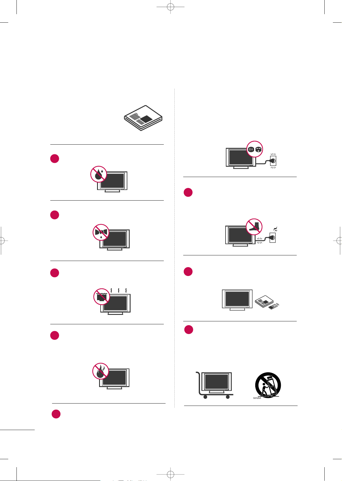
Do not use this apparatus near water.
Clean only with dry cloth.
Do not block any ventilation openings. Install in
accordance with the manufacturer’s instructions.
Do not install near any heat sources such as
radiators, heat registers, stoves, or other
apparatus (including amplifiers)that produce
heat.
Do not defeat the safety purpose of the polarized
or grounding-type plug. A polarized plug has
two blades with one wider than the other. A
grounding type plug has two blades and a
third grounding prong, The wide blade or the
third prong are provided for your safety. If the
provided plug does not fit into your outlet,
consult an electrician for replacement of the
obsolete outlet.
Protect the power cord from being walked on
or pinched particularly at plugs, convenience
receptacles, and the point where they exit from
the apparatus.
Only use attachments/accessories specified by
the manufacturer.
Use only with the cart, stand, tripod, bracket,
or table specified by the manufacturer, or sold
with the apparatus. When a cart is used, use
caution when moving the cart/apparatus combination to avoid injury from tip-over.
1
2
3
4
5
7
6
8
MFL59166615-Edit1-en 12/2/09 3:37 PM Page 2
3
Unplug this apparatus during lighting storms
or when unused for long periods of time.
Refer all servicing to qualified service personnel.
Servicing is required when the apparatus has
been damaged in any way, such as powersupply cord or plug is damaged, liquid has
been spilled or objects have fallen into the
apparatus, the apparatus has been exposed to
rain or moisture, does not operate normally, or
has been dropped.
Never touch this apparatus or antenna during
a thunder or lighting storm.
When mounting a TV on the wall, make sure
not to install the TV by the hanging power and
signal cables on the back of the TV.
Do not allow an impact shock or any objects to
fall into the product, and do not drop onto the
screen with something.
CAUTION concerning the Power Cord:
It is recommend that appliances be placed
upon a dedicated circuit; that is, a single
outlet circuit which powers only that appliance
and has no additional outlets or branch
circuits. Check the specification page of this
owner's manual to be certain.
Do not connect too many appliances to the
same AC power outlet as this could result in
fire or electric shock.
Do not overload wall outlets. Overloaded wall
outlets, loose or damaged wall outlets, extension
cords, frayed power cords, or damaged or
cracked wire insulation are dangerous. Any of
these conditions could result in electric shock
or fire. Periodically examine the cord of your
appliance, and if its appearance indicates damage
or deterioration, unplug it, discontinue use of
the appliance, and have the cord replaced with
an exact replacement part by an authorized
servicer. Protect the power cord from physical
or mechanical abuse, such as being twisted,
kinked, pinched, closed in a door, or walked
upon. Pay particular attention to plugs, wall
outlets, and the point where the cord exits the
appliance.
Do not make the TV with the power cord
plugged in. Do not use a damaged or loose
power cord. Be sure do grasp the plug when
unplugging the power cord. Do not pull on the
power cord to unplug the TV.
WARNING - To reduce the risk of fire or electrical
shock, do not expose this product to rain,
moisture or other liquids. Do not touch the TV
with wet hands. Do not install this product
near flammable objects such as gasoline or
candles or expose the TV to direct air
conditioning.
9
10
12
11
14
13
15
MFL59166615-Edit1-en 12/2/09 3:37 PM Page 3
4
SAFETY INSTRUCTIONS
Do not expose to dripping or splashing and do
not place objects filled with liquids, such as
vases, cups, etc. on or over the apparatus (e.g.
on shelves above the unit).
GGRROOUUNNDDIINN GG
Ensure that you connect the earth ground wire
to prevent possible electric shock (i.e. a TV
with a three-prong grounded AC plug must be
connected to a three-prong grounded AC outlet). If grounding methods are not possible,
have a qualified electrician install a separate
circuit breaker.
Do not try to ground the unit by connecting it
to telephone wires, lightening rods, or gas
pipes.
DDIISSCCOONNNNEECCTTIINNGG DDEEVVIICCEE FFRROOMM MMAAIINNSS
Mains plug is the disconnecting device. The
plug must remain readily operable.
As long as this unit is connected to the AC wall
outlet, it is not disconnected from the AC
power source even if you turn off this unit by
SWITCH.
CClleeaanniinngg
When cleaning, unplug the power cord and
scrub gently with a soft cloth to prevent
scratching. Do not spray water or other liquids
directly on the TV as electric shock may occur.
Do not clean with chemicals such as alcohol,
thinners or benzene.
MMoovviinngg
Make sure the product is turned off, unplugged
and all cables have been removed. It may take 2
or more people to carry larger TVs. Do not
press against or put stress on the front panel of
the TV.
VVeennttiillaattiioonn
Install your TV where there is proper ventilation.
Do not install in a confined space such as a
bookcase. Do not cover the product with cloth
or other materials (e.g.) plastic while plugged in.
Do not install in excessively dusty places.
If you smell smoke or other odors coming from
the TV or hear strange sounds, unplug the power
cord contact an authorized service center.
Do not press strongly upon the panel with
hand or sharp object such as nail, pencil or pen,
or make a scratch on it.
Keep the product away from direct sunlight.
16
17
18
19
Power
Supply
Short-circuit
Breaker
20
23
24
25
21
22
MFL59166615-Edit1-en 12/2/09 3:37 PM Page 4
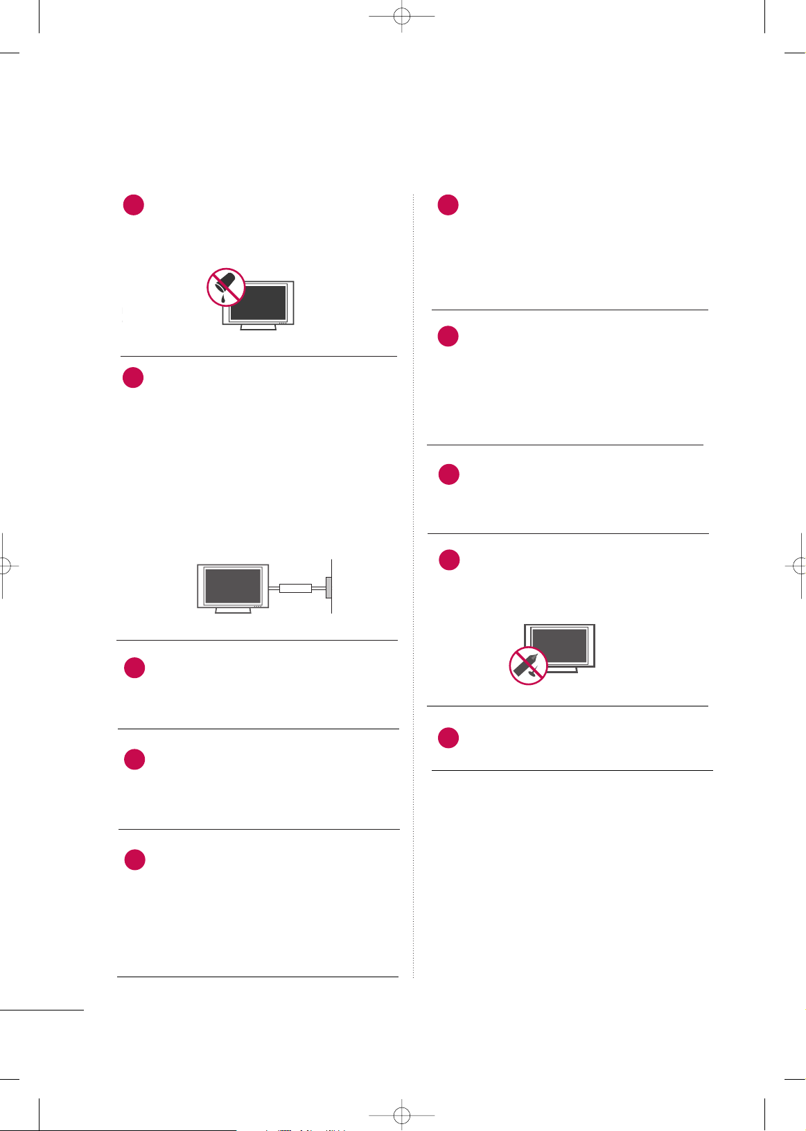
FFoorr LLCCDD TTVV
If the TV feels cold to the touch, there may be
a small “flicker” when it is turned on. This is
normal, there is nothing wrong with TV.
Some minute dot defects may be visible on the
screen, appearing as tiny red, green, or blue
spots. However, they have no adverse effect on
the monitor's performance.
Avoid touching the LCD screen or holding your
finger(s) against it for long periods of time.
Doing so may produce some temporary distortion effects on the screen.
5
ON DISPOSAL
(Only Hg lamp used LCD TV)
The fluorescent lamp used in this product contains
a small amount of mercury. Do not dispose of
this product with general household waste.
Disposal of this product must be carried out in
accordance to the regulations of your local authority.
26
MFL59166615-Edit1-en 12/22/09 6:35 PM Page 5
6
CONTENTS
SAFETY INSTRUCTIONS
. . . . . . . . . . . . . . . . . . . . . . . . . . 2
FEATURE OF THIS TV
. . . . . . . . . . . . . . . . . . . . . . . . . . . . . . . 8
PREPARATION
Accessories
. . . . . . . . . . . . . . . . . . . . . . . . . . . . . . . . . . . . . . . . . . . . . . . . . . . . . . 9
Front Panel Information . . . . . . . . . . . . . . . . . . . . . . . . . . . . . . . . . . . 10
Back Panel Information
. . . . . . . . . . . . . . . . . . . . . . . . . . . . . . . . . . . . 16
Stand Instruction
. . . . . . . . . . . . . . . . . . . . . . . . . . . . . . . . . . . . . . . . . . . . . 19
VESA Wall Mounting
. . . . . . . . . . . . . . . . . . . . . . . . . . . . . . . . . . . . . . . . 27
Cable Management
. . . . . . . . . . . . . . . . . . . . . . . . . . . . . . . . . . . . . . . . . 28
Attaching the TV to a Desk
. . . . . . . . . . . . . . . . . . . . . . . . . . . . . . 32
Desktop Pedestal Installation
. . . . . . . . . . . . . . . . . . . . . . . . . . . 33
Swivel Stand
. . . . . . . . . . . . . . . . . . . . . . . . . . . . . . . . . . . . . . . . . . . . . . . . . . . 33
Securing the TV to the wall to prevent falling when
the TV is used on a stand
. . . . . . . . . . . . . . . . . . . . . . . . . . . . . . . . 34
Antenna or Cable Connection
. . . . . . . . . . . . . . . . . . . . . . . . . . 35
EXTERNAL EQUIPMENT SETUP
HD Receiver Setup
. . . . . . . . . . . . . . . . . . . . . . . . . . . . . . . . . . . . . . . . . 36
DVD Setup
. . . . . . . . . . . . . . . . . . . . . . . . . . . . . . . . . . . . . . . . . . . . . . . . . . . . . 39
VCR Setup . . . . . . . . . . . . . . . . . . . . . . . . . . . . . . . . . . . . . . . . . . . . . . . . . . . . . 41
Other A/V Source Setup
. . . . . . . . . . . . . . . . . . . . . . . . . . . . . . . . . 42
PC Setup
. . . . . . . . . . . . . . . . . . . . . . . . . . . . . . . . . . . . . . . . . . . . . . . . . . . . . . . . 43
USB Connection
. . . . . . . . . . . . . . . . . . . . . . . . . . . . . . . . . . . . . . . . . . . . 49
Audio Out Connection
. . . . . . . . . . . . . . . . . . . . . . . . . . . . . . . . . . . 49
WATCHING TV / CHANNEL CONTROL
Remote Control Functions . . . . . . . . . . . . . . . . . . . . . . . . . . . . . . . 50
Turning On the TV
. . . . . . . . . . . . . . . . . . . . . . . . . . . . . . . . . . . . . . . . . . 56
Channel Selection . . . . . . . . . . . . . . . . . . . . . . . . . . . . . . . . . . . . . . . . . . . 56
Volume Adjustment
. . . . . . . . . . . . . . . . . . . . . . . . . . . . . . . . . . . . . . . . . 56
Initial Setting
. . . . . . . . . . . . . . . . . . . . . . . . . . . . . . . . . . . . . . . . . . . . . . . . . . . 57
On-Screen Menus Selection
. . . . . . . . . . . . . . . . . . . . . . . . . . . . . 58
Quick Menu
. . . . . . . . . . . . . . . . . . . . . . . . . . . . . . . . . . . . . . . . . . . . . . . . . . . 60
Channel Setup
- Auto Scan (Auto Tuning)
. . . . . . . . . . . . . . . . . . . . . . . . . . . 61
- Add / Delete Channel (Manual Tuning)
. . . . . . 62
- Channel Editing
. . . . . . . . . . . . . . . . . . . . . . . . . . . . . . . . . . . . . . . . 63
Channel List
. . . . . . . . . . . . . . . . . . . . . . . . . . . . . . . . . . . . . . . . . . . . . . . . . . . . 64
Favorite Channel Setup
. . . . . . . . . . . . . . . . . . . . . . . . . . . . . . . . . . . . 65
Favorite Channel List . . . . . . . . . . . . . . . . . . . . . . . . . . . . . . . . . . . . . . . 65
Brief Information . . . . . . . . . . . . . . . . . . . . . . . . . . . . . . . . . . . . . . . . . . . . . 66
Scan Option
. . . . . . . . . . . . . . . . . . . . . . . . . . . . . . . . . . . . . . . . . . . . . . . . . . . 67
System Color . . . . . . . . . . . . . . . . . . . . . . . . . . . . . . . . . . . . . . . . . . . . . . . . . . .68
Input List
. . . . . . . . . . . . . . . . . . . . . . . . . . . . . . . . . . . . . . . . . . . . . . . . . . . . . . . . 69
Input Label
. . . . . . . . . . . . . . . . . . . . . . . . . . . . . . . . . . . . . . . . . . . . . . . . . . . . . 70
AV Mode
. . . . . . . . . . . . . . . . . . . . . . . . . . . . . . . . . . . . . . . . . . . . . . . . . . . . . . . . 71
Simple Manual
. . . . . . . . . . . . . . . . . . . . . . . . . . . . . . . . . . . . . . . . . . . . . . . . 71
SIMPLINK . . . . . . . . . . . . . . . . . . . . . . . . . . . . . . . . . . . . . . . . . . . . . . . . . . . . . . .
72
EPG
. . . . . . . . . . . . . . . . . . . . . . . . . . . . . . . . . . . . . . . . . . . . . . . . . . . . . . . . . . . . . . . . 74
BLUETOOTH
Bluetooth . . . . . . . . . . . . . . . . . . . . . . . . . . . . . . . . . . . . . . . . . . . . . . . . . . . . . . . 77
Setting the Bluetooth
. . . . . . . . . . . . . . . . . . . . . . . . . . . . . . . . . . . . . . 78
Setting TV Pin
. . . . . . . . . . . . . . . . . . . . . . . . . . . . . . . . . . . . . . . . . . . . . . . . . 79
Connecting the Bluetooth Headset
. . . . . . . . . . . . . . . . . . 80
Managing Registered Bluetooth Device
. . . . . . . . . . . . . 82
My Bluetooth Information
. . . . . . . . . . . . . . . . . . . . . . . . . . . . . . . 83
Viewing the Photos with Bluetooth Device
. . . . . . . . 84
Listening the Musics with Bluetooth Device
. . . . . . 85
TIME MACHINE
Precautions when using the USB Device . . . . . . . . . . . 86
Time Machine (Pause & Replay of Live TV)
. . . . . . . 87
Recording
. . . . . . . . . . . . . . . . . . . . . . . . . . . . . . . . . . . . . . . . . . . . . . . . . . . . . . . 91
Schedule
. . . . . . . . . . . . . . . . . . . . . . . . . . . . . . . . . . . . . . . . . . . . . . . . . . . . . . . 95
Recorded TV
. . . . . . . . . . . . . . . . . . . . . . . . . . . . . . . . . . . . . . . . . . . . . . . . . . 97
MULTIMEDIA
Entry Modes . . . . . . . . . . . . . . . . . . . . . . . . . . . . . . . . . . . . . . . . . . . . . . . . 10 0
Photo List
. . . . . . . . . . . . . . . . . . . . . . . . . . . . . . . . . . . . . . . . . . . . . . . . . . . . 101
Music List
. . . . . . . . . . . . . . . . . . . . . . . . . . . . . . . . . . . . . . . . . . . . . . . . . . . . . 10 5
Movie List
. . . . . . . . . . . . . . . . . . . . . . . . . . . . . . . . . . . . . . . . . . . . . . . . . . . . . 10 8
DivX Registration Code
. . . . . . . . . . . . . . . . . . . . . . . . . . . . . . . . . . 113
Deactivation
. . . . . . . . . . . . . . . . . . . . . . . . . . . . . . . . . . . . . . . . . . . . . . . . . . 114
MFL59166615-Edit1-en 12/2/09 3:37 PM Page 6
7
PICTURE CONTROL
Picture Size (Aspect Ratio) Control . . . . . . . . . . . . . . . . . 115
Picture Wizard
. . . . . . . . . . . . . . . . . . . . . . . . . . . . . . . . . . . . . . . . . . . . . . . . 118
Preset Picture Settings(Picture Mode)
. . . . . . . . . . . . 12 0
Manual Picture Adjustment - User Mode
. . . . . . . . . 121
Picture Improvement Technology
. . . . . . . . . . . . . . . . . . . . 12 2
Expert Picture Control
. . . . . . . . . . . . . . . . . . . . . . . . . . . . . . . . . . . 123
Energy Saving
. . . . . . . . . . . . . . . . . . . . . . . . . . . . . . . . . . . . . . . . . . . 12 6
Picture Reset
. . . . . . . . . . . . . . . . . . . . . . . . . . . . . . . . . . . . . . . . . . . . . . . . 12 7
Image Sticking Minimization(ISM) Method
. . . . . 12 8
Power Indicator
. . . . . . . . . . . . . . . . . . . . . . . . . . . . . . . . . . . . . . . . . . . . 12 9
LED Local Dimming
. . . . . . . . . . . . . . . . . . . . . . . . . . . . . . . . . . . . . . . 12 9
Demo Mode
. . . . . . . . . . . . . . . . . . . . . . . . . . . . . . . . . . . . . . . . . . . . . . . . . 13 0
SOUND & LANGUAGE CONTROL
Auto Volume Leveler (Auto Volume)
. . . . . . . . . . . . . . . . 131
Clear Voice II
. . . . . . . . . . . . . . . . . . . . . . . . . . . . . . . . . . . . . . . . . . . . . . . . . 132
Preset Sound Settings (Sound Mode)
. . . . . . . . . . . . . 13 3
Sound Setting Adjustment - User Mode
. . . . . . . . . . 13 4
Balance
. . . . . . . . . . . . . . . . . . . . . . . . . . . . . . . . . . . . . . . . . . . . . . . . . . . . . . . . . 13 5
TV Speakers On/Off Setup
. . . . . . . . . . . . . . . . . . . . . . . . . . . . 13 6
Digital Audio Out
. . . . . . . . . . . . . . . . . . . . . . . . . . . . . . . . . . . . . . . . . 13 7
Audio Reset
. . . . . . . . . . . . . . . . . . . . . . . . . . . . . . . . . . . . . . . . . . . . . . . . . 13 8
Stereo/SAP Broadcast Setup
. . . . . . . . . . . . . . . . . . . . . . . . . . 13 9
Audio Language
. . . . . . . . . . . . . . . . . . . . . . . . . . . . . . . . . . . . . . . . . . . . .
14 0
On-Screen Menus Language Selection
. . . . . . . . . . . . 141
Caption Mode
- Analog Broadcasting System Captions
. . . . . . 14 2
- Digital Broadcasting System Captions
. . . . . . 14 3
TIME SETTING
Clock Setting
- Auto Clock Setup
. . . . . . . . . . . . . . . . . . . . . . . . . . . . . . . . . . . 14 4
- Manual Clock Setup
. . . . . . . . . . . . . . . . . . . . . . . . . . . . . . . 14 5
Auto On/Off Time Setting
. . . . . . . . . . . . . . . . . . . . . . . . . . . . 14 6
Sleep Timer Setting
. . . . . . . . . . . . . . . . . . . . . . . . . . . . . . . . . . . . . . . 14 7
PARENTAL CONTROL / RATINGS
Set Password & Lock System . . . . . . . . . . . . . . . . . . . . . . . . . . 14 8
Channel Blocking
. . . . . . . . . . . . . . . . . . . . . . . . . . . . . . . . . . . . . . . . . . . 151
Rating(Movie Rating)
. . . . . . . . . . . . . . . . . . . . . . . . . . . . . . . . . . . . . 15 2
External Input Blocking
. . . . . . . . . . . . . . . . . . . . . . . . . . . . . . . . . .
15 3
Key lock . . . . . . . . . . . . . . . . . . . . . . . . . . . . . . . . . . . . . . . . . . . . . . . . . . . . . . . . 15 4
APPENDIX
Troubleshooting . . . . . . . . . . . . . . . . . . . . . . . . . . . . . . . . . . . . . . . . . . . .155
Maintenance . . . . . . . . . . . . . . . . . . . . . . . . . . . . . . . . . . . . . . . . . . . . . . . . . 156
Product Specifications . . . . . . . . . . . . . . . . . . . . . . . . . . . . . . . . . . . 15 7
Programming the Remote Control
. . . . . . . . . . . . . . . . . . 15 9
IR Codes . . . . . . . . . . . . . . . . . . . . . . . . . . . . . . . . . . . . . . . . . . . . . . . . . . . . .162
External Control Through RS-232C
. . . . . . . . . . . . . . . . .16 4
Open Source License . . . . . . . . . . . . . . . . . . . . . . . . . . . . . . . . . . . . . .17 2
MFL59166615-Edit1-en 12/2/09 3:37 PM Page 7
8
FEATURE OF THIS TV
■
This feature is not available for all models.
■
When a fixed image (e.g. logos, screen menus, video game, and computer display) is displayed on the TV
for an extended period, it can become permanently imprinted on the screen. This phenomenon is known
as “image burn” or “burn-in.” Image burn is not covered under the manufacturer’s warranty.
■
In order to prevent image burn, avoid displaying a fixed image on your TV screen for a prolonged period
(2 or more hours for LCD, 1 or more hours for Plasma).
■
Image burn can also occur on the letterboxed
areas of your TV if you use the 4:3 aspect
ratio setting for an extended period.
IMPORTANT INFORMATION TO PREVENT “IMAGE BURN
/ BURN-IN” ON YOUR TV SCREEN
is a trademark of SRS Labs, Inc.
TruSurround XT technology is incorporated under
license from SRS Labs, Inc.
Manufactured under license from Dolby Laboratories.
“
Dolby
“and the double-D symbol are trademarks of
Dolby Laboratories.
The AV Mode optimizes the picture into Cinema,
Sports, and game Mode according to the video and
audio content. The viewer has the ability to quickly
choose the correct mode for the picture they are
viewing.
Automatically enhances and amplifies the sound of
human voice frequency range to help keep dialogue
audible when background noise swells.
LG TV include a unique invisible speaker system,
tuned by renowned audio expert, Mr. Mark Levinson.
Speakers are embedded in strategic spots behind the
front cabinet and use minute vibrations to turn the
entire front bezel into the speaker system. The result
is a clean, polished look, and enhanced audio by
increasing the “sweet spot”, giving a wider and richer
sound field.
High-definition television. High-resolution digital
television broadcast and playback system composed
of roughly a million or more pixels, 16:9 aspect-ratio
screens, and HE-AAC digital audio. A subset of digital television, HDTV formats include 1080i and 720p
resolutions.
Displays HDTV programs in full 1920 x 1080p resolution for a more detailed picture.
(This feature is not available for all models.)
THX Cinema mode is recommended for watching
movies. Designed for use in a dark room.
(This feature is not available for all models.)
“DivX Certified to play DivX video up to HD 1080p,
including premium content”
ABOUT DIVX VIDEO: DivX
®
is a digital video format
created by DivX,Inc. This is an official DivX Certified
device that plays DivX video. Visit www.divx.com for
more information and software tools to convert your
files into DivX video.
ABOUT DIVX VIDEO-ON-DEMAND: This DivX
Certified®device must be registered in order to play
DivX Video-on-Demand (VOD) content. To generate
the registration code, locate the DivX VOD section in
the device setup menu. Go to vod.divx.com with this
code to complete the registration process and learn
more about DivX VOD.
Listen to TV with wireless headset, or enjoy viewing
your mobile phone photos on your TV.
(This feature is not available for all models.)
Advance 120Hz panel provides clearer, smoother
images, even during fast action scenes creating a more
stable structure for a crisper picture.
TruMotion 240Hz displays 240 scenes per second by
combining advanced 120Hz technology with scanning
backlight. This technology is verified from Intertek
&TüV Rheinland.
MFL59166615-Edit1-en 12/2/09 3:37 PM Page 8
PREPARATION
9
PREPARATION
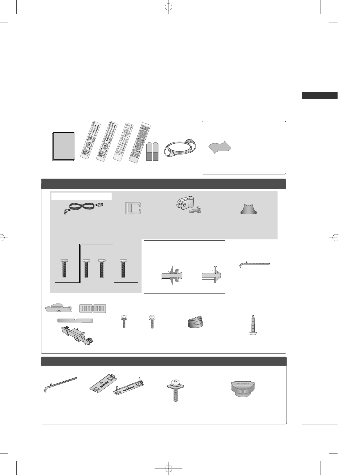
ACCESSORIES
Ensure that the following accessories are included with your TV. If an accessory is missing, please contact the
dealer where you purchased the TV.
The accessories included may differ from the images below.
1.5V 1.5V
Owner’s Manual
Power Cord
Remote Control,
Batteries
M
U
T
E
TV
P
O
W
ER
Q
.
M
E
NU M
E
NU
AV MODERET
U
RN
ENT
E
R
VOL
C
H
1
2
3
4
56
78
0
9
Q.VIEW
P
A
G
E
LIST
ENERGY SAVING
STB
FAV
MARK
INPU
T
GUIDE
C
H
AR/NU
M
DELE
T
E
LIVE TV
TIME CONTROL
REPEAT
* Wipe spots on the exterior
only with the polishing
cloth.
* Do not wipe roughly when
removing stain. Excessive
pressure may cause
scratch or discoloration.
Polishing Cloth
Cable Management
Clip
(Refer to p.29)
Protection Cover
Bolts for stand assembly (Refer to p. 19, p. 25)
Stand Rear Cover
(Refer to p.19, 20)
(For 42LH70**,
42/47SL90**)
x 3 x 4
M4x20 M4x16
(For 32LH70**)
x 7
M4x20
Protective Bracket and
Bolt for Power Cord
(Refer to P.28)
(For 42/47LH70**)
(For 47LH70**)
x 8
M4x16
USB Extension Cable
* Make sure to use the provided USB
extension cable, Which is specially
designed for a slim fit.
FFoorr 3322//4422//4477LLHH7700****
Screw for stand fixing
(Refer to P.32)
(Except 42/47LH70**,
47/55LH50**, 47/55LH90**
)
Not included with all models
Protection Cover
(Refer to P.26)
PPLLAASSMMAA TTVV mmooddeellss
Cable Holder
x 2
or
Cable management
clip
(Refer to P.31)
(For 50/
60PS80**
)
1
23
456
78
0
9
Bolts for stand assembly
(Refer to P.21, P.23, P.24)
x 4
(Except
55LH50**,
55LH90**,
32/42/47LH70**
)
or
Bolts for stand assembly
(Refer to P.26)
x 4
(Except
60PS80**
)
LLCCDD TTVV mmooddeellss
or
(For 42/47LH70**, 32/42/47SL80**, 42/47SL90**)
Use screws 12mm(
±
0.5
) long on the SET assembly side.
(sold separately)
12mm
12mm
with guide spacer
without guide spacer
or
Cable Management Clip
(Refer to P.29, P.30)
(For
32/42/47/55SL80**,42/47SL90**)
Cable Holder
(For
32/42/47/55SL80**,
42/47SL90**)
x 8
(for
32/42/47S
L80**)
1
23
456
78
0
9
or
or
P
O
W
E
R
A
V
M
O
D
E
E
N
E
R
G
Y
S
A
V
I
N
G
C
H
V
O
L
F
A
V
M
A
R
K
/
D
E
L
E
T
E
M
U
T
E
O
N
/
O
F
F
123
45
0
6
789
L
IS
T
INPUT
M
EN
U
RATIO
Q.MENU
Q.VIEW
R
E
T
U
R
N
G
U
I
D
E
I
N
F
O
E
N
T
E
R
A
B
C
D
E
F
M
N
O
J
K
L
P
Q
R
S
C
H
A
R
/
N
U
M
G
H
I
T
U
V
W
X
Y
Z
R
E
P
E
A
T
L
I
V
E
T
V
T
I
M
E
C
O
N
T
R
O
L
T
V
P
A
G
E
(Except
42/47SL90**
)
MFL59166615-Edit1-en 12/3/09 11:46 AM Page 9
PREPARATION
10
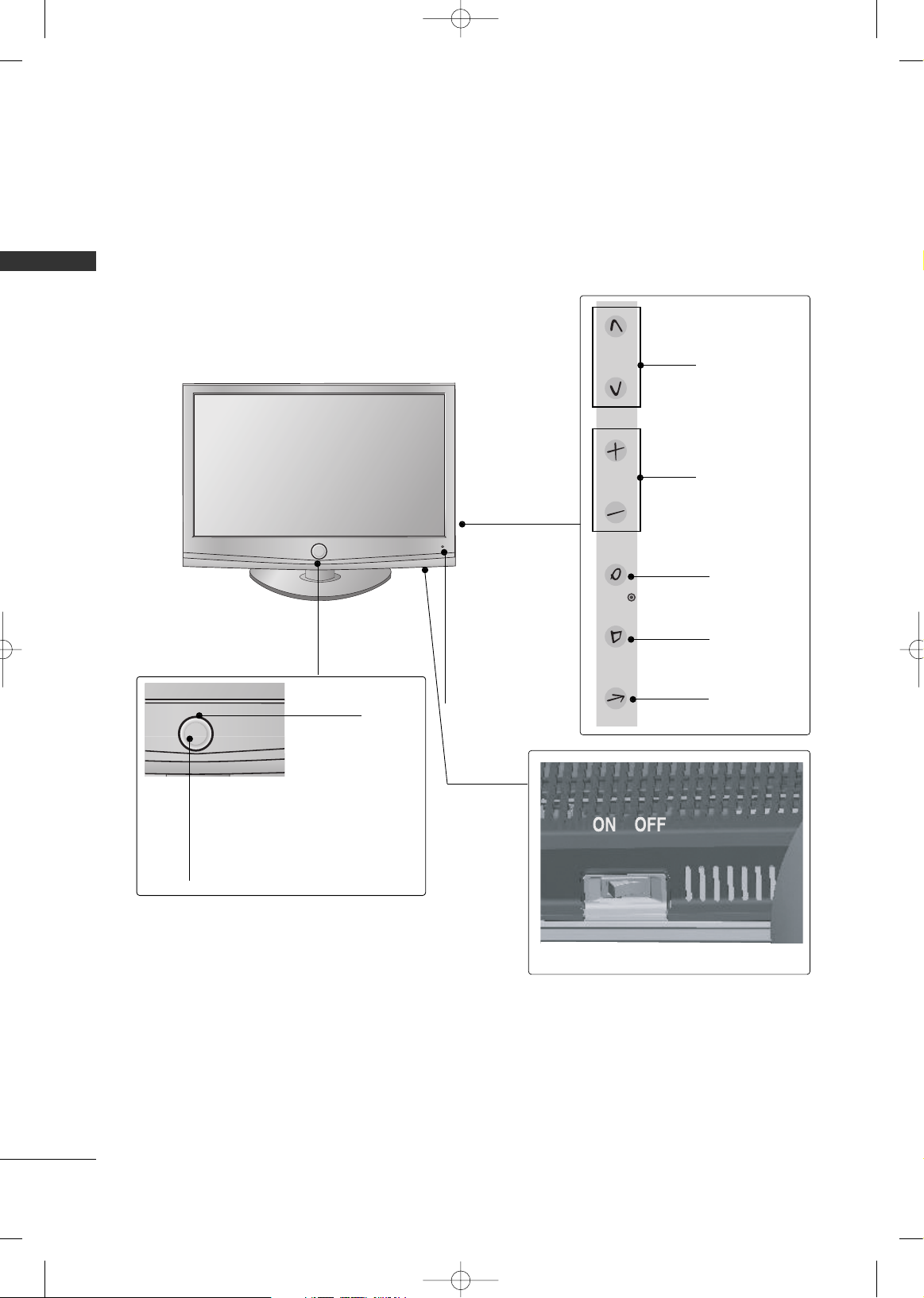
PREPARATION
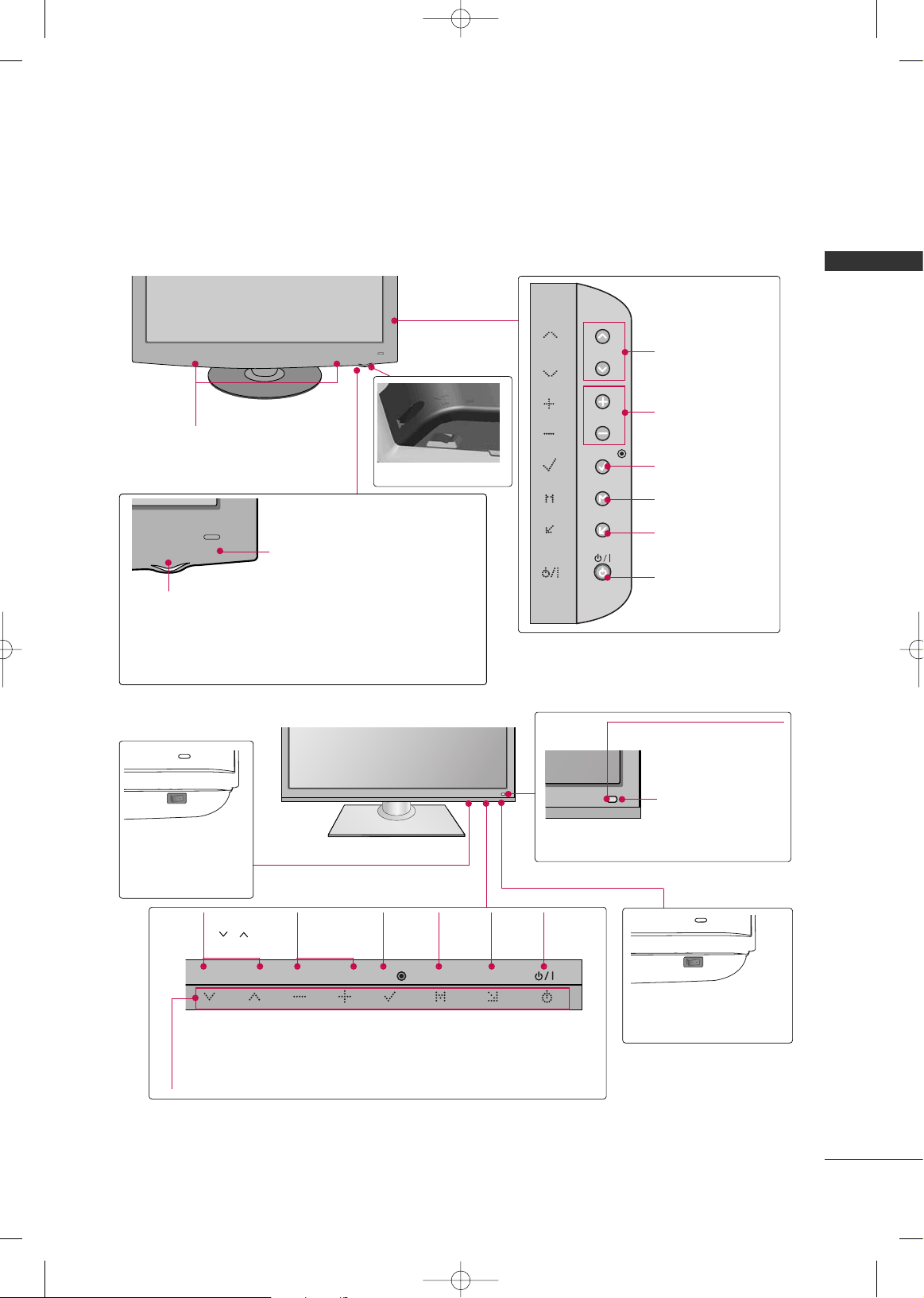
FRONT PANEL INFORMATION
■
Image shown may differ from your TV.
CHANNEL
Buttons
VOLUME
Buttons
ENTER Button
MENU Button
INPUT Button
AC power control switch
POWER Button (Touch Sensor) ,
Power/Standby Indicator
Illuminates red in standby mode.
Illuminates white when the TV is
switched on.
Remote Control
Sensor,
Intelligent Sensor
Adjusts picture
according to the
surrounding conditions
Moving LED
LCD TV Models -
32/42/47LH70**
MFL59166615-Edit1-en 12/2/09 3:38 PM Page 10
CH
VOL
ENTER
MENU
INPUT
PREPARATION
11
CHANNEL
Buttons
VOLUME
Buttons
ENTER Button
MENU Button
INPUT Button
POWER Button
SPEAKER
Remote Control Sensor,
Power/Standby Indicator
Illuminates red in standby mode.
Illuminates blue when the TV is switched on.
AC power control switch
O
N
O
F
F
32/37/42LH35**
MFL59166615-Edit1-en 12/2/09 3:38 PM Page 11
CH
VOL
ENTER
MENU
INPUT
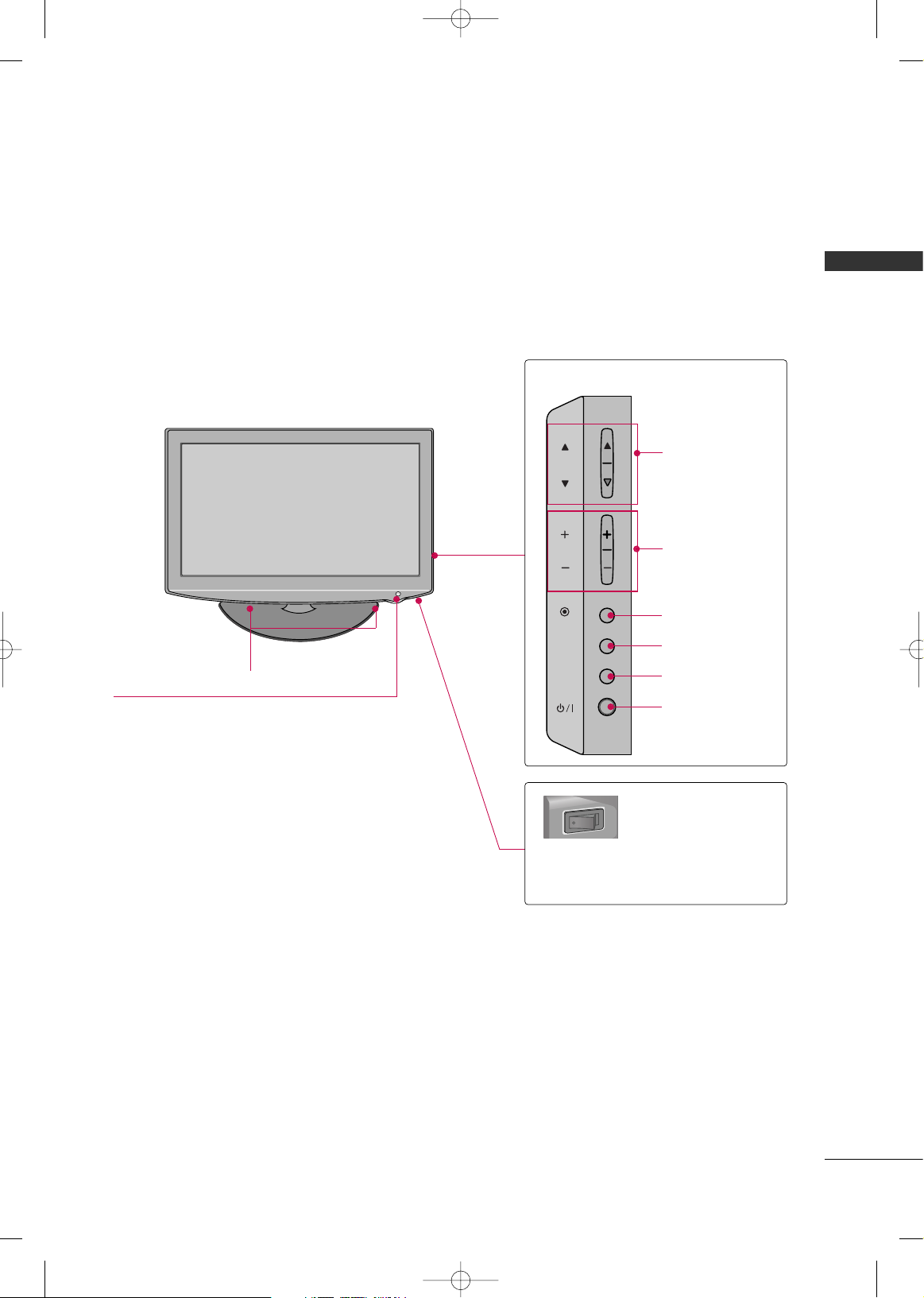
PREPARATION
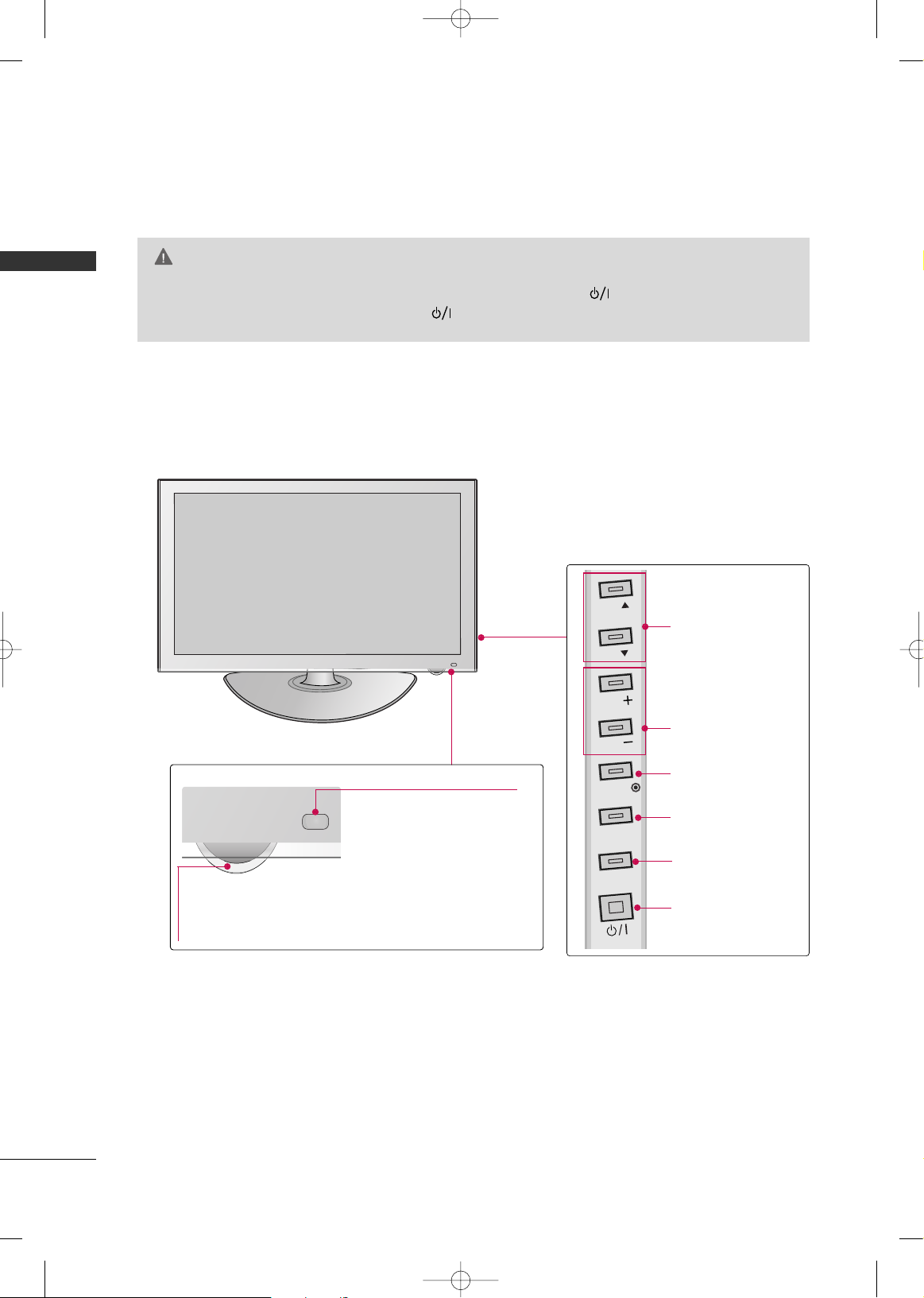
12
PREPARATION
42/47/55LH50**
CHANNEL
Buttons
VOLUME
Buttons
ENTER Button
MENU Button
INPUT Button
POWER Button
Remote Control Sensor,
Intelligent Sensor
Adjusts picture according to
the surrounding conditions
AC power control switch
OFF ON
SPEAKER
Power/Standby Indicator
Illuminates red in standby mode.
Illuminates blue when the TV is switched on.
42/47SL90**
Remote Control Sensor
Intelligent Sensor
Adjusts picture
according to the
surrounding conditions
Main power switch
OFF ON
CHANNEL
Buttons
VOLUME
Buttons
ENTER Button
MENU Button
INPUT Button
POWER Button
Power/Standby
Indicator
Illuminates red in
standby mode.
Illuminates white
when the TV is
switched on.
MFL59166615-Edit1-en 12/2/09 3:38 PM Page 12
CH
VOL
ENTER
MENU
INPUT
CH
VOL
ENTER
MENU
INPUT
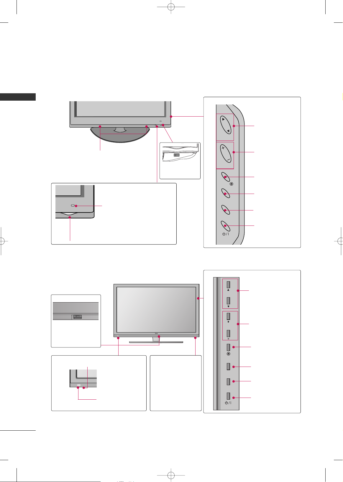
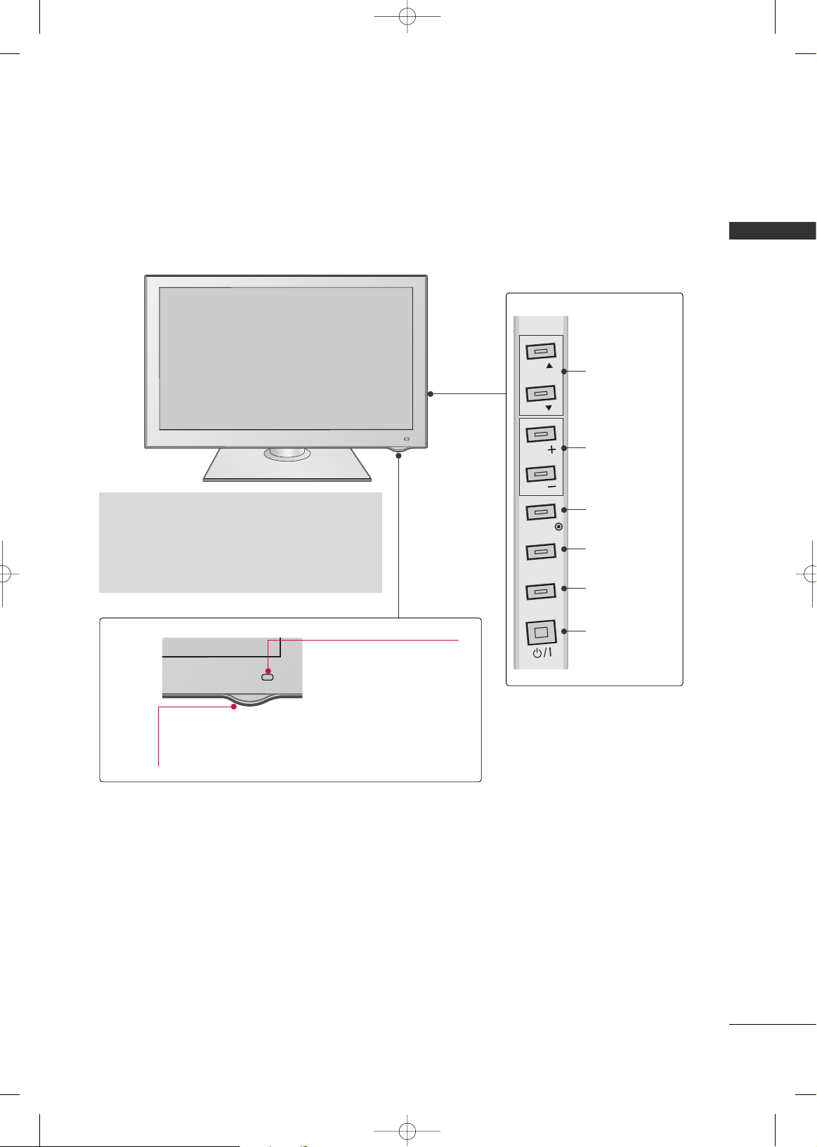
PREPARATION
13
CHANNEL
Buttons
VOLUME
Buttons
ENTER Button
MENU Button
INPUT Button
POWER Button
AC power control switch
SPEAKER
Power/Standby Indicator
Illuminates red in standby mode.
Illuminates white when the TV is switched on.
Remote Control Sensor,
Intelligent Sensor
Adjusts picture according to the
surrounding conditions
42/47/55LH90**
32/42/47/55SL80**
Main power switch
(For 42/47/55SL80)
OFF ON
Remote Control Sensor
INPUT
Button
POWER
Button
MENU
Button
ENTER
Button
CHANNEL
( , )
Buttons
VOLUME
(-, +)
Buttons
Power/Standby Indicator
Illuminates red in standby mode.
Illuminates blue when the TV is switched on (Can be adjusted
using the
PPoowweerr IInnddiiccaattoo rr
in the OPTION menu.
GG
pp ..99 66
).
Intelligent Sensor
Adjusts picture
according to the
surrounding conditions
Main power switch
(For 32SL80)
ON OFF
MFL59166615-Edit1-en 12/2/09 3:38 PM Page 13
CH
VOL
ENTER
MENU
INPUT
CH
VOL
ENTER
MENU
INPUT
PREPARATION
14
PREPARATION
PLASMA TV Models -
Power/Standby Indicator
Illuminates red in standby mode.
Illuminates white when the TV is switched on
and goes out slowly .
42/50PQ60
CHANNEL
Buttons
VOLUME
Buttons
ENTER Button
MENU Button
INPUT Button
POWER Button
Remote Control Sensor
Intelligent Sensor
Adjusts picture according to
the surrounding conditions.
GG
When the TV cannot be turned on with the remote control, press the (power) button on the TV.
(The remote control will not work when the (power) button on the TV is switched off. )
CAUTION
MFL59166615-Edit1-en 12/2/09 3:38 PM Page 14
CH
CH
VOL
VOL
ENTER
MENU
INPUT
PREPARATION
15
CHANNEL
Buttons
VOLUME
Buttons
ENTER Button
MENU Button
INPUT Button
POWER Button
42/50PS80**
Power/Standby Indicator
Illuminates red in standby mode.
The LED is off while the TV remains on.
Remote Control Sensor
Intelligent Sensor
Adjusts picture according to
the surrounding conditions.
G
Do not step on the glass stand or subject it to
any impact.It may break, causing possible injury
from fragments of glass, or the TV may fall.
G
Do not drag the TV. The floor or the product may
be damaged.
MFL59166615-Edit1-en 12/2/09 3:38 PM Page 15
CH
CH
VOL
VOL
ENTER
MENU
INPUT
PREPARATION
16
PREPARATION
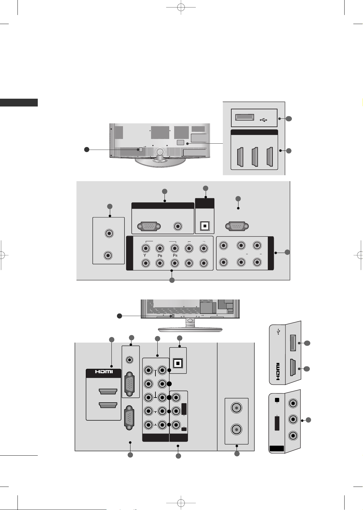
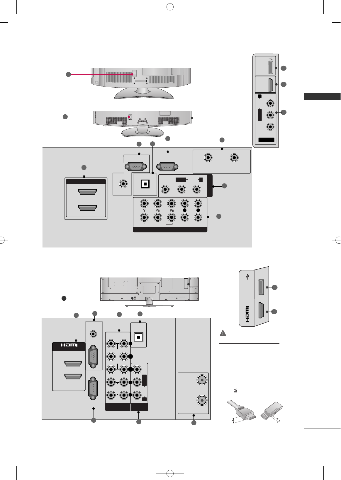
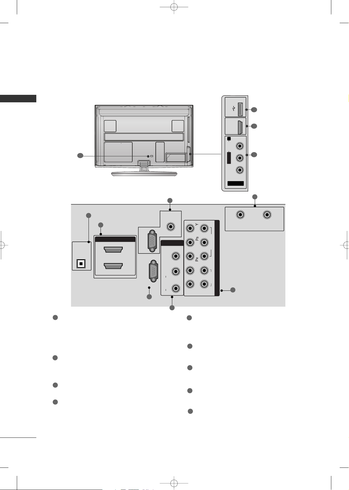
BACK PANEL INFORMATION
■
Image shown may differ from your TV.
9
RS-232C IN
(CONTROL & SERVICE)
CABLE IN
ANTENNA IN
COMPONENT IN
1
2
VIDEO
AUDIO
L
R
AV IN
L(MONO)
R
AUDIO
VIDEO
1
2
RGB IN
AUDIO
(RGB/DVI)
RGB (PC)
OPTICAL
DIGITAL
AUDIO OUT
2
3
4
5
6
7
HDMI/DVI IN
1
2
3
USB IN
1
8
LCD TV Models -
32/42/47LH70**
CABLE IN
ANTENA
IN
R
AUDIO IN
(RGB/DVI)
2
1
/DVI IN
RGB IN (PC)
DIGITAL
AUDIO OUT
OPTICAL
(
CONTROL &
SERVICE)
RS-232C IN
21
VIDEO
AUDIO
MONO
( )
AUDIOVIDEO LR
COMPONENT IN
AV IN 1
L R
Y P
B
P
R
2
4
3
6
5
1
7
32/37/42/47/55SL80**
9
6
1
8
MFL59166615-Edit1-en 12/2/09 3:38 PM Page 16
USB IN
IN 3
R
AUDIO
L/MONO
VIDEO
AV IN 2
1
8
PREPARATION
17
32/37/42LH35**, 42/47/55LH50**
42/47/55LH90**
9
9
R
HDMI/DVI IN
2
1
AUDIO IN
OPTICAL DIGITAL
AUDIO OUT
RGB IN (PC)
RS-232C IN
(CONTROL & SERVICE)
CABLE IN
ANTENNA IN
COMPONENT IN
VIDEO
AUDIO
AV IN 1
AUDIO
VIDEO
(RGB/DVI)
L/MONO
R
2
1
L
R
1
2
3
4
5
7
6
AV IN 2
L/MONO
R
AUDIO
VIDEO
USB IN
HDMI
IN 3
6
1
8
R
2
4
3
6
5
1
7
42/47SL90**
9
GG
For an optimal connection,
HDMI cables and USB
devices should have bezels
less than 0.39 inches
(10mm) Thick.
*A 0.39 inches (10mm)
CAUTION
For HDMI IN 3 and USB IN
MFL59166615-Edit1-en 12/2/09 3:38 PM Page 17
2
1
/DVI IN
AUDIO IN
(RGB/DVI)
(
CONTROL &
SERVICE)
RGB IN (PC)
RS-232C IN
COMPONENT IN
21
Y P
B
P
R
L R
DIGITAL
AUDIO OUT
OPTICAL
AV IN
VIDEO
AUDIO
( )
MONO
AUDIOVIDEO LR
CABLE IN
ANTENA
IN
USB IN
IN 3
PREPARATION
18
PREPARATION
PLASMA TV Models
AV IN 2
L/MONO
R
AUDIO
VIDEO
USB IN
HDMI IN 3
6
1
8
R
1
2
3
4
5
7
6
9
HDMI/DVI IN, HDMI IN
Digital Connection.
Supports HD video and Digital audio. Doesn’t
support 480i.
Accepts DVI video using an adapter or HDMI to
DVI cable (not included).
OPTICAL DIGITAL AUDIO OUT
Digital optical audio output for use with amps and
home theater systems.
Note: In standby mode, this port doesn’t work.
RS-232C IN (CONTROL & SERVICE) PORT
Used by third party devices.
AUDIO IN (RGB/DVI)
1/8" (0.32 cm) headphone jack for analog PC audio input.
RGB IN (PC)
Analog PC Connection. Uses a D-sub 15 pin cable
(VGA cable).
COMPONENT IN
Analog Connection. Supports HD.
Uses a red, green, and blue cable for video & red
and white for audio.
AV (Audio/Video) IN
Analog composite connection. Supports standard
definition video only.
ANTENNA/CABLE IN
Connect over-the air signals to this jack.
Connect cable signals to this jack.
USB IN
Used for viewing photos and listening to MP3 and
playing movies.
Power Cord Socket
For operation with AC power.
Caution: Never attempt to operate the TV on DC
power.
1
2
3
4
5
8
6
7
9
MFL59166615-Edit1-en 12/2/09 3:38 PM Page 18
OPTICAL
DIGITAL
AUDIO OUT
HDMI/DVI IN
AUDIO IN
(RGB/DVI)
AV IN 1
2
1
RGB IN (PC)
RS-232C IN
(CONTROL & SERVICE)
VIDEO
L/MONO
AUDIO
R
L
R
1
2
CABLE IN
VIDEO
COMPONENT IN
AUDIO
ANTENNA IN
PREPARATION
19
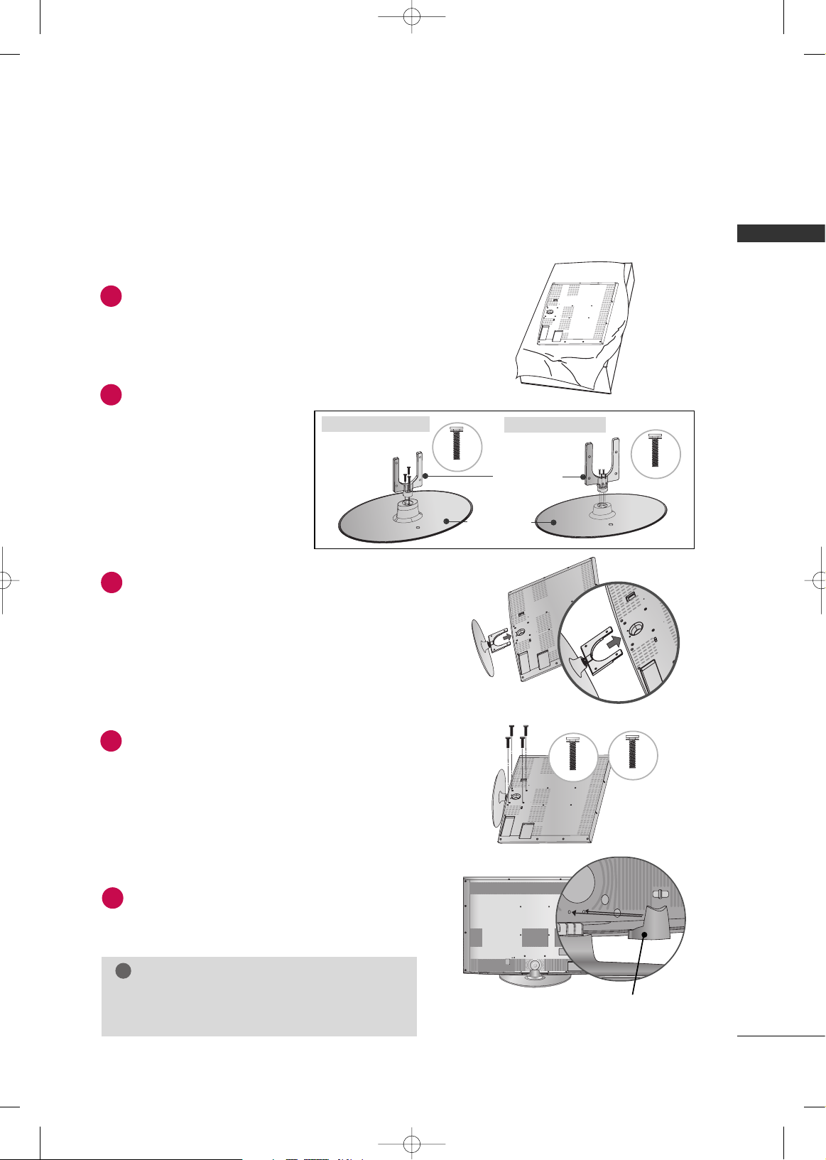
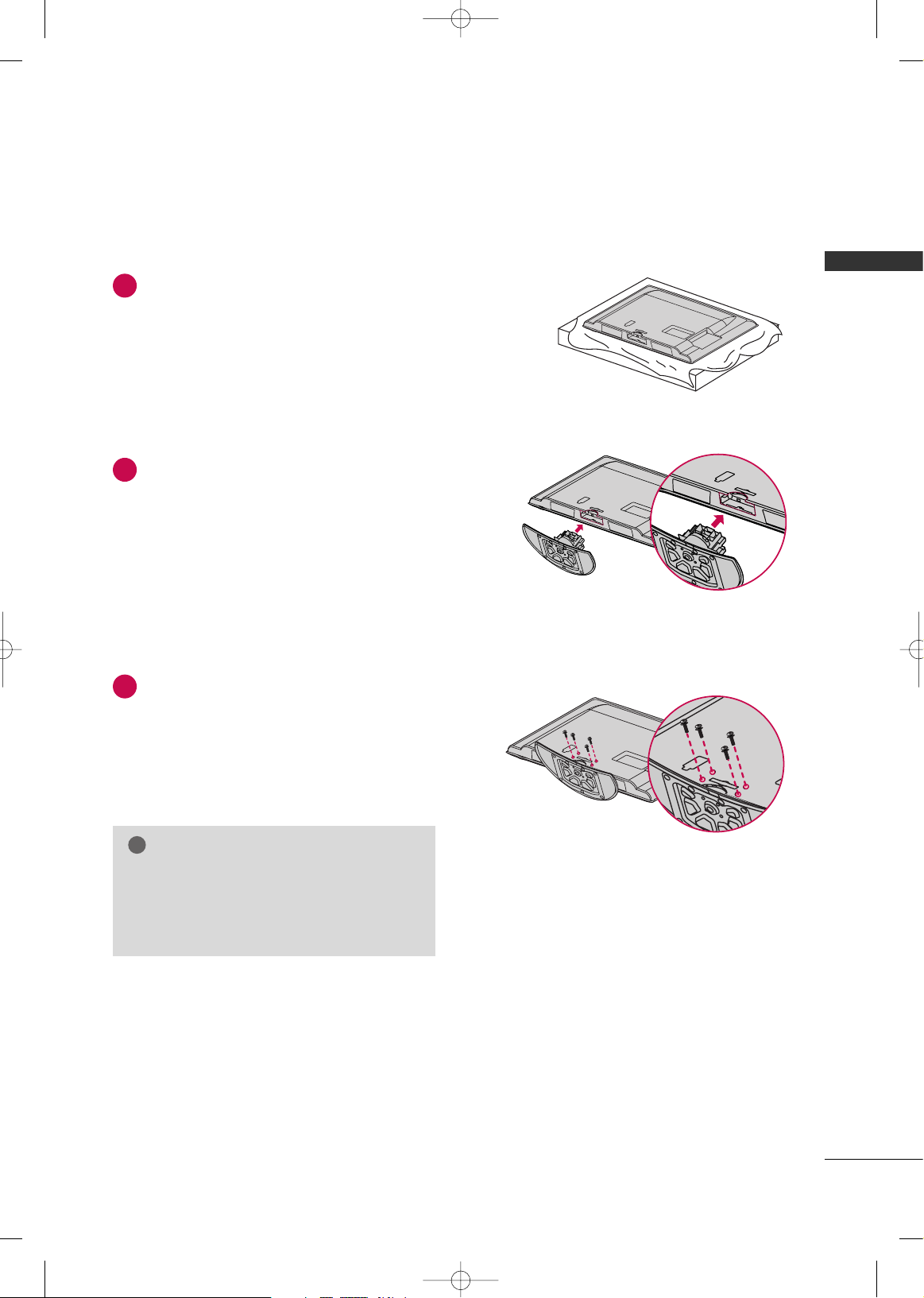
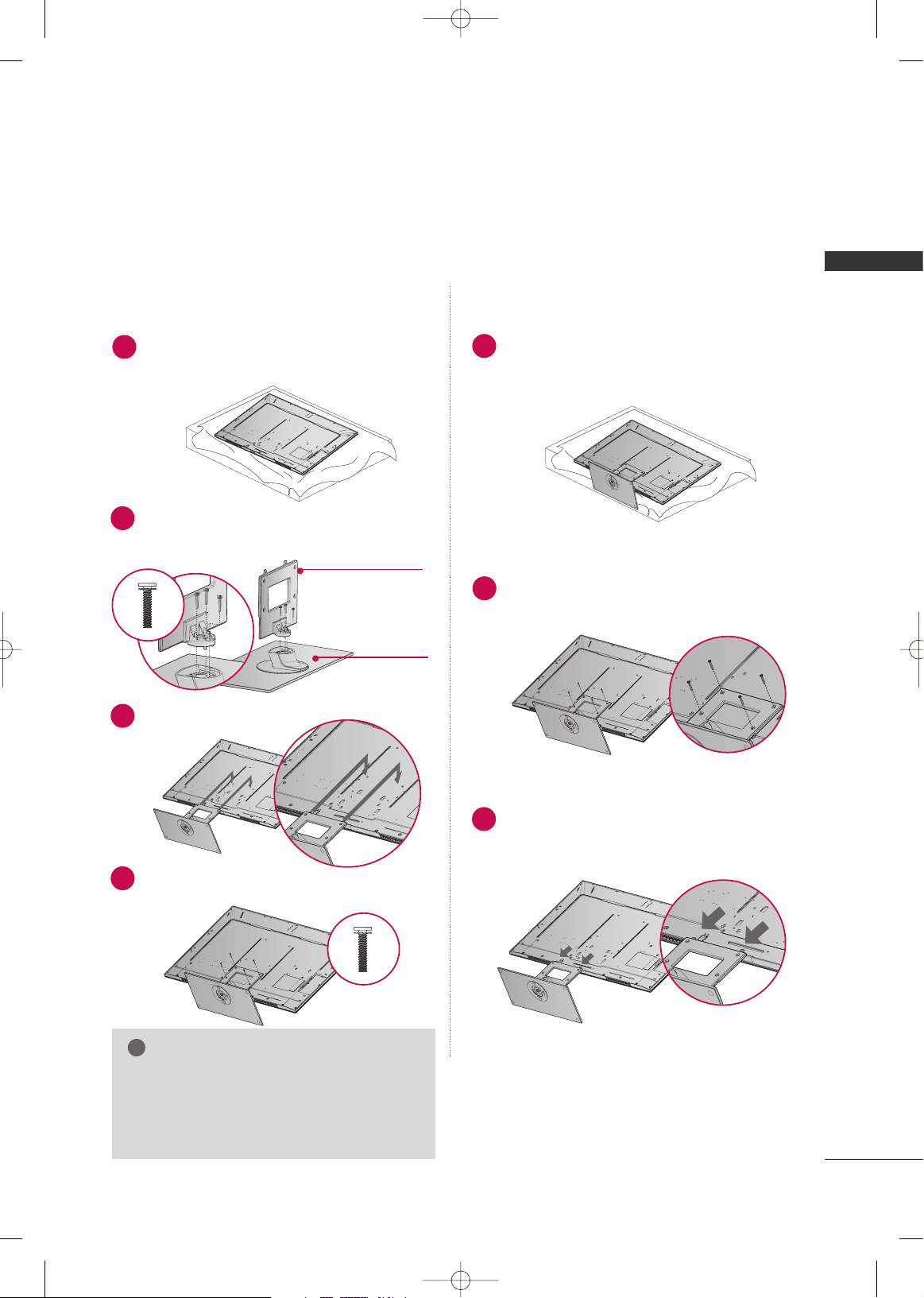
STAND INSTRUCTION
■
Image shown may differ from your TV.
Carefully place the TV screen side down on a
cushioned surface to protect the screen from
damage.
Assemble the parts of the
SS TT AANNDD BB OODD YY
with
the
CCOOVVEERR BBAASSEE
of the TV.
Fix the 4 bolts securely using the holes in the
back of the TV.
1
2
4
INSTALLATION
GG
When assembling the desk type stand, make sure the bolt
is fully tightened (If not tightened fully, the TV can tilt forward after the product installation). Do not over tighten.
NOTE
!
4477LLHH7700 YYDD
Assemble the TV as shown.
3
M4x20
M4x16
Stand Body
Stand Base
3322LLHH7700YYDD,, 4422LL HH 7700 YYDD
M4x20
3322LLHH7700 YYDD
M4x16
4422//4477 LLHH7700YYDD
Install the
SSTTAANNDD RREEAARR CCOOVVEERR
as shown.
5
SS TTAANNDD RREE AARR CCOOVVEERR
LCD TV Models -
32/42/47LH70**
MFL59166615-Edit1-en 12/2/09 3:38 PM Page 19
PREPARATION
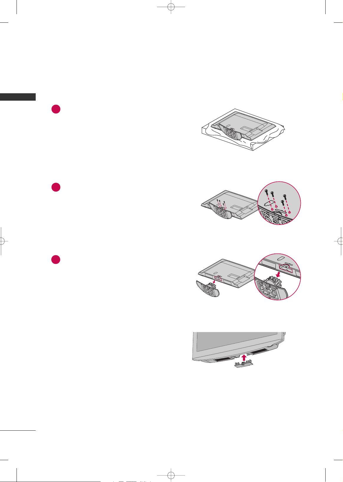
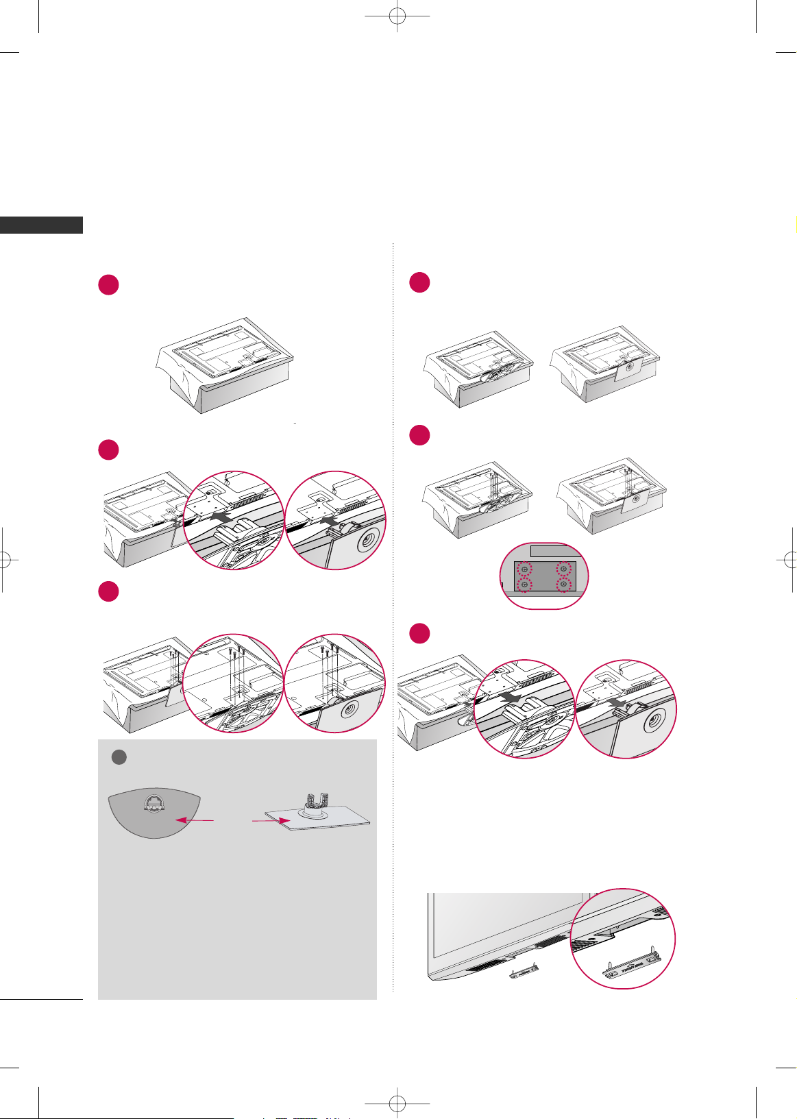
20
PREPARATION
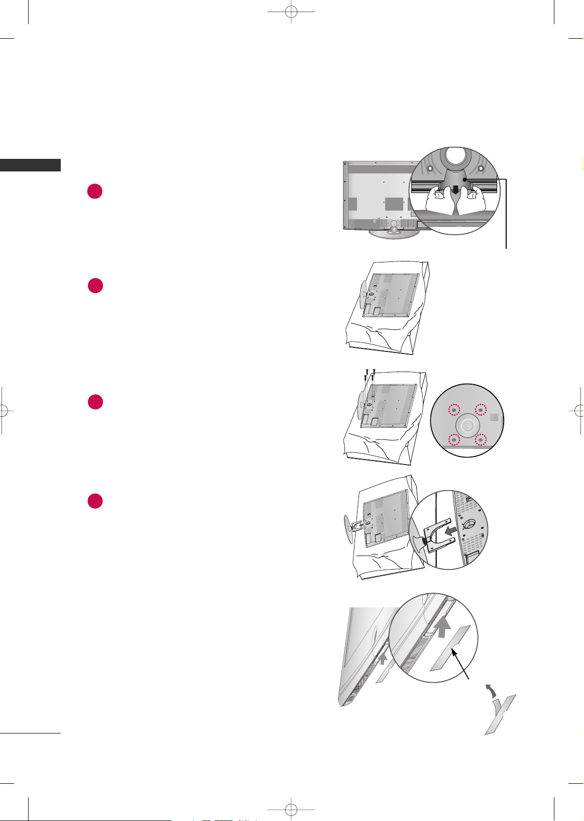
DETACHMENT
Carefully place the TV screen side down on a
cushioned surface to protect the screen from
damage.
2
Loose the bolts from TV.
3
Detach the stand from TV.
4
After removing the protection paper from the
protection cover, adhere it to the TV as shown.
PROTECTION COVER
Detach the
SSTTAANNDD RREEAARR CCOOVVEERR
as shown.
Grip the knob in your fingers and pull it.
1
SS TTAANNDD RREE AARR CCOOVVEERR
MFL59166615-Edit1-en 12/2/09 3:38 PM Page 20
PREPARATION
21
Carefully place the TV screen side down on a
cushioned surface to protect the screen from
damage.
Assemble the TV as shown.
Fix the 4 bolts securely using the holes in the
back of the TV.
1
2
3
INSTALLATION (Except
55LH50**)
GG
When assembling the desk type stand, make sure
the bolt is fully tightened (If not tightened fully,
the TV can tilt forward after the product installation). Do not over tighten.
NOTE
!
32/37/42LH35**, 42/47/55LH50**
MFL59166615-Edit1-en 12/2/09 3:38 PM Page 21
PREPARATION
22
PREPARATION
DETACHMENT
Carefully place the TV screen side down on a
cushioned surface to protect the screen from
damage.
1
Loose the bolts from TV.
2
Detach the stand from TV.
3
After removing the stand, install the included
pprrootteeccttii oonn ccoovveerr
over the hole for the stand.
Press the
PPRROOTTEECCTTIIOONN CCOOVVEERR
into the TV
until you hear it click.
PROTECTION COVER
MFL59166615-Edit1-en 12/2/09 3:38 PM Page 22
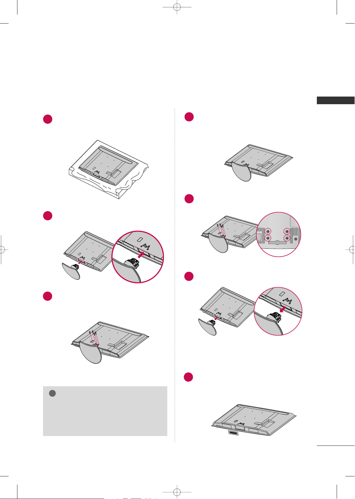
PREPARATION
23
42/47/55LH90**
Carefully place the TV screen side down on a
cushioned surface to protect the screen from
damage.
Assemble the TV as shown.
Fix the 4 bolts securely using the holes in the
back of the TV.
1
2
3
INSTALLATION (
Except 55LH90**)
GG
When assembling the desk type stand, make sure
the bolt is fully tightened (If not tightened fully,
the TV can tilt forward after the product installation). Do not over tighten.
NOTE
!
DETACHMENT
Carefully place the TV screen side down on a
cushioned surface to protect the screen from
damage.
1
Loose the bolts from TV.
2
Detach the stand from TV.
3
PROTECTION COVER
Insert the
PP RR OOTTEECCTTIIOONN CC OOVVEERR
into the TV.
After removing the protection paper from the
protection cover, adhere it to the TV as shown.
4
MFL59166615-Edit1-en 12/2/09 3:38 PM Page 23
PREPARATION
24
PREPARATION
For 32/42/47/55SL80**
Carefully place the TV screen side down on a
cushioned surface to protect the screen from
damage.
1
INSTALLATION (
Except 55SL80**)
GG
When assembling the desk type stand, make sure
the screws are fully tightened (If not tightened
fully, the TV can tilt forward after the product
installation). Do not over tighten.
NOTE
!
DETACHMENT
Carefully place the TV screen side down on a
cushioned surface to protect the screen from
damage.
1
Remove the screws from the TV.
2
Detach the stand from TV.
3
PROTECTION COVER
After removing the stand, install the included
pprrootteeccttii oonn ccoovveerr
over the hole for the stand.
Press the
PPRROOTTEECCTTIIOONN CCOOVVEERR
into the TV
until you hear it click.
4
Fix the 4 screws securely using the holes in the
back of the TV.
4
Assemble the parts of the
SS ttaanndd BBoo ddyy
with
the
SS ttaanndd BBaassee
of the TV.
Assemble the TV as shown.
2
3
SS TTAANNDD BBOO DDYY
SS TTAANNDD BBAASSEE
MFL59166615-Edit1-en 12/2/09 3:38 PM Page 24
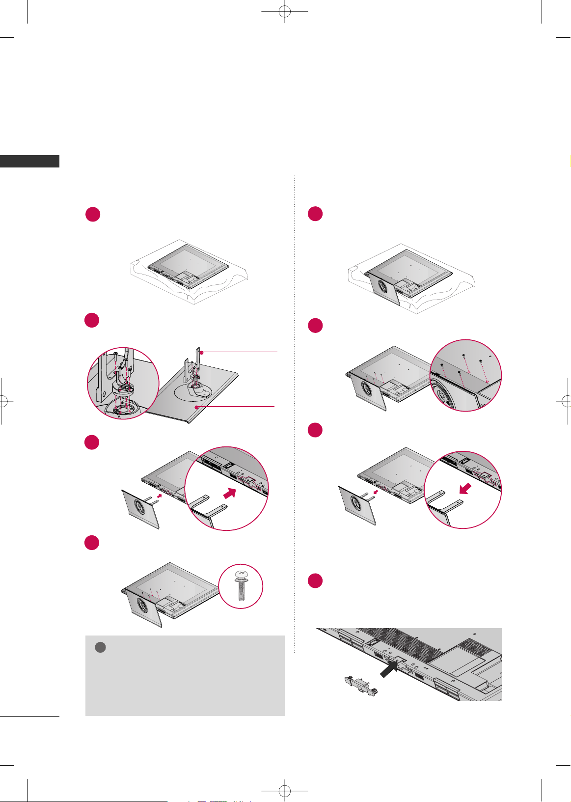
PREPARATION
25
For 42/47SL90**
Carefully place the TV screen side down on a
cushioned surface to protect the screen from
damage.
1
INSTALLATION
GG
When assembling the desk type stand, make sure
the screws are fully tightened (If not tightened
fully, the TV can tilt forward after the product
installation). Do not over tighten.
NOTE
!
DETACHMENT
Carefully place the TV screen side down on a
cushioned surface to protect the screen from
damage.
1
Remove the screws from the TV.
2
Detach the stand from TV.
3
Fix the 4 screws securely using the holes in the
back of the TV.
4
Assemble the parts of the
SS ttaanndd BBoo ddyy
with
the
SS ttaanndd BBaassee
of the TV.
Assemble the TV as shown.
2
3
SS TTAANNDD BBOO DDYY
SS TTAANNDD BBAASSEE
16 m m
20m m
MFL59166615-Edit1-en 12/2/09 3:38 PM Page 25
PREPARATION
26
PREPARATION
PLASMA TV Models
Carefully place the TV screen side down on a
cushioned surface to protect the screen from
damage.
Assemble the TV as shown.
1
2
Fix the 4 bolts securely using the holes in the
back of the TV.
3
Carefully place the TV screen side down on a
cushioned surface to protect the screen from
damage.
1
Loose the bolts from TV.
2
Detach the stand from TV.
3
After removing the stand, install the included
pprrootteeccttii oonn ccoovveerr
over the hole for the stand.
Press the
PPRROOTTEECCTTIIOONN CCOOVVEERR
into the TV
until you hear it click.
PROTECTION COVER
GG
When assembling the desk type stand, check
whether the bolt is fully tightened. (If not tightened fully, the product can tilt forward after the
product installation). If you tighten the bolt with
excessive force, the bolt can deviate from abrasion of the tightening part of the bolt.
NOTE
!
INSTALLATION
DETACHMENT
GG
When assembling the stand, make sure to distinguish
and assemble the front and rear side of the stand
correctly.
FRONT
MFL59166615-Edit1-en 12/2/09 3:38 PM Page 26
PREPARATION
27
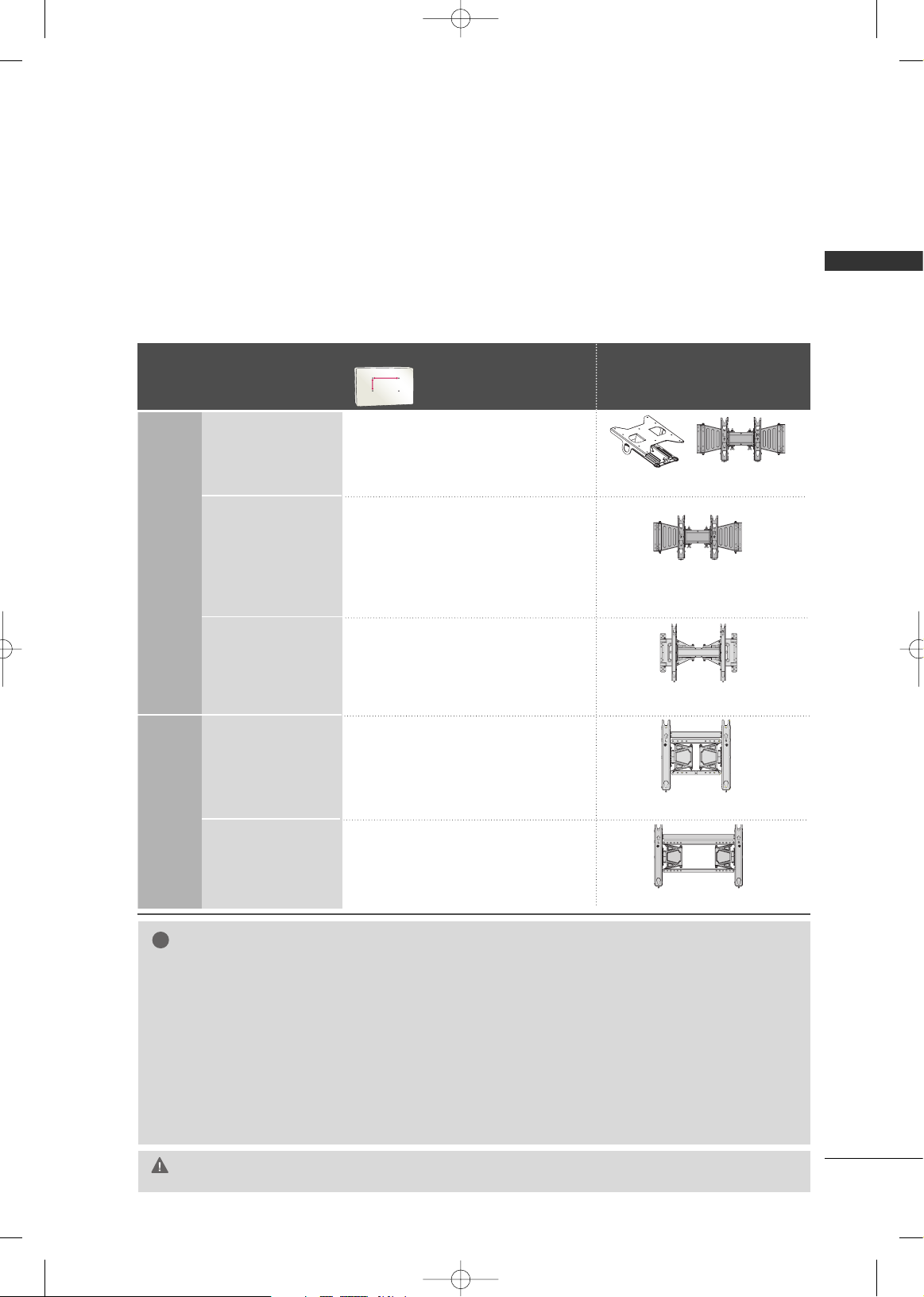
VESA WALL MOUNTING
Install your wall mount on a solid wall perpendicular to the floor. When attaching to other building materials, please
contact your nearest installer.
If installed on a ceiling or slanted wall, it may fall and result in severe personal injury.
We recommend that you use an LG brand wall mount when mounting the TV to a wall.
LG recommends that wall mounting be performed by a qualified professional installer.
First you connect the USB extension cable to the USB IN terminal, and then hang it on the wall.(For 32/42/47LH70**)
GG
Do not install your wall mount kit while your TV is turned on. It may result in personal
injury due to electric shock.
CAUTION
GG
Screw length needed depends on the wall mount
used. For further information, refer to the instructions included with the mount.
GG
Standard dimensions for wall mount kits are shown
in the table.
GG
When purchasing our wall mount kit, a detailed
installation manual and all parts necessary for
assembly are provided.
GG
Do not use screws longer then the standard dimension, as they may cause damage to the inside to
the TV.
GG
For wall mounts that do not comply with the VESA
standard screw specifications, the length of the
screws may differ depending on their specifications.
GG
Do not use screws that do not comply with the
VESA standard screw specifications.
Do not use fasten the screws too strongly, this may
damage the TV or cause the TV to a fall, leading to
personal injury. LG is not liable for these kinds of
accidents.
GG
LG is not liable for TV damage or personal injury
when a non-VESA or non specified wall mount is
used or the consumer fails to follow the TV installation instructions.
NOTE
!
Model
VESA (A *B)
Standard Screw Quantity
Wall Mounting Bracket
(sold separately)
32LH70**,
32LH35**,32SL80**
200* 10 0 M 4 4
AA
BB
AW-47LG30M
AW-47LG30M
42LH70**, 47LH70**,
37LH35**, 42LH35**,
42LH50**, 47LH50**,
42LH90**, 47LH90**,
42SL80**, 47SL80**,
42SL90**, 47SL90**
200* 200 M6 4
RW230
55LH50**,
55LH90**55SL80**
400* 400 M6 4
AW-55LH40M
AW-50PG60MS
42PQ60*, 50PQ60*,
50PS80**
400* 400 M6 4
60PS80**
600* 400 M8 4
AW-60PG60MS
LCD
TV
Models
PLASMA
TV
Models
MFL59166615-Edit1-en 12/2/09 3:38 PM Page 27
PREPARATION
28
PREPARATION
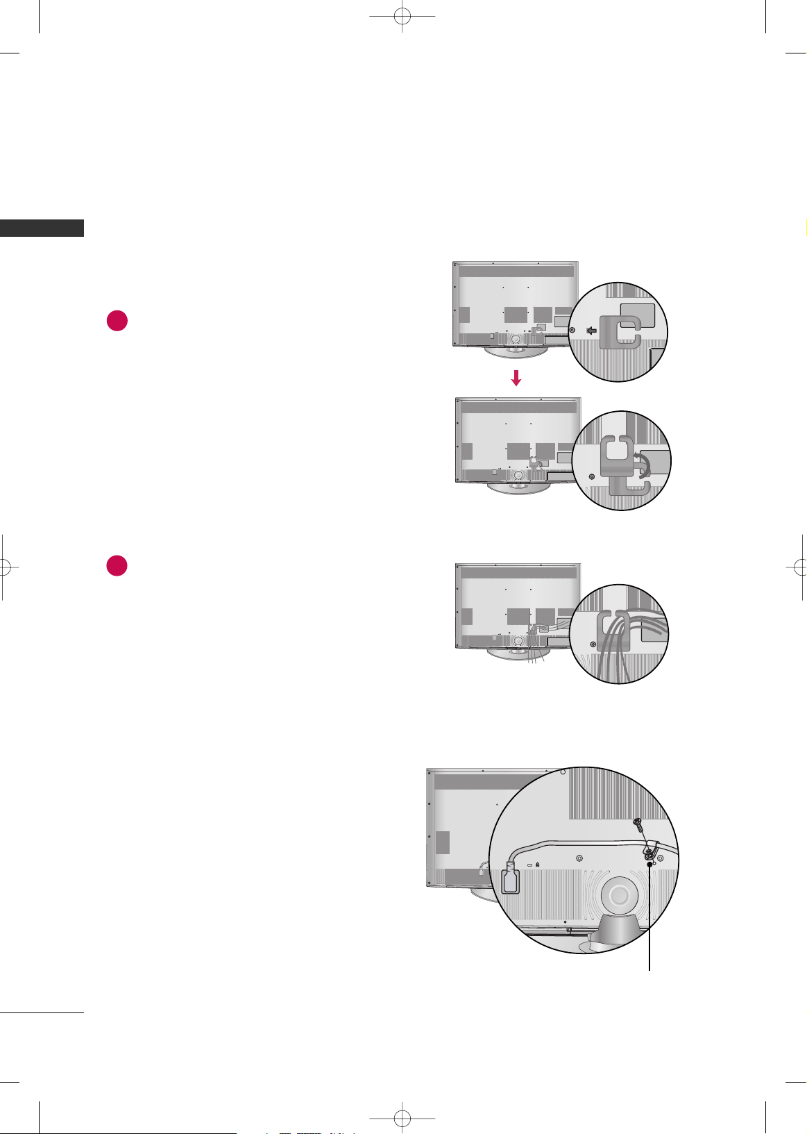
CABLE MANAGEMENT
Align the hole with the tab on the
CCAABBLLEE
MMAANNAAGG EEMMEENNTT CCLLIIPP
.
Turn the
CCAABBLLEE MMAANNAAGGEE MMEENNTT CCLLIIPP
as
shown.
Note: This cable management clip can be bro-
ken by excessive pressure.
Connect the cables as necessary.
To connect additional equipment, see the
EXTERNAL EQUIPMENT SETUP section.
1
2
■
Image shown may differ from your TV.
HOW TO SECURE THE POWER CABLE
Secure the power cable with the
PP RR OO TTEECCTTIIVVEE
BBRRAACCKKEETT
and the bolt as shown. It will help prevent the power cable from being removed by accident.
PP RROOTT EECCTTIIVVEE BBRRAACC KK EETT
LCD TV Models -
32/42/47LH70**
MFL59166615-Edit1-en 12/2/09 3:38 PM Page 28
PREPARATION
29
32/37/42LH35**,
42/47/55LH50**, 42/47/55LH90**
Connect the cables as necessary.
To connect additional equipment, see the
EXTERNAL EQUIPMENT SETUP section.
Install the CABLE MANAGEMENT CLIP as
shown.
CABLE MANAGEMENT CLIP
1
2
Put the cables inside the CABLE MANAGEMENT CLIP and snap it closed.
3
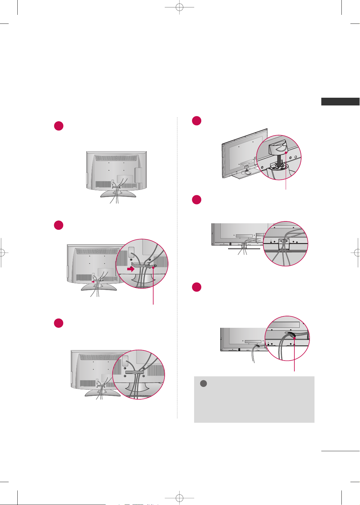
32/42/47/55SL80**
Install the CABLE MANAGEMENT CLIP as
shown.
1
Connect the cables as necessary.
To connect additional equipment, see the
EXTERNAL EQUIPMENT SETUP section.
Install CABLE HOLDER as shown and bundle
the cables.
1
Connect the cables as necessary.
To connect additional equipment, see the
EXTERNAL EQUIPMENT SETUP section.
2
GG
Do not hold the CABLE MANAGEMENT
CLIP when moving the TV.
- If the TV is dropped, you may be injured
or the product may be broken.
NOTE
!
FOR DESK-TYPE STAND
FOR WALL MOUNT
CABLE MANAGEMENT CLIP
CABLE HOLDER
MFL59166615-Edit1-en 12/2/09 3:38 PM Page 29
PREPARATION
30
PREPARATION
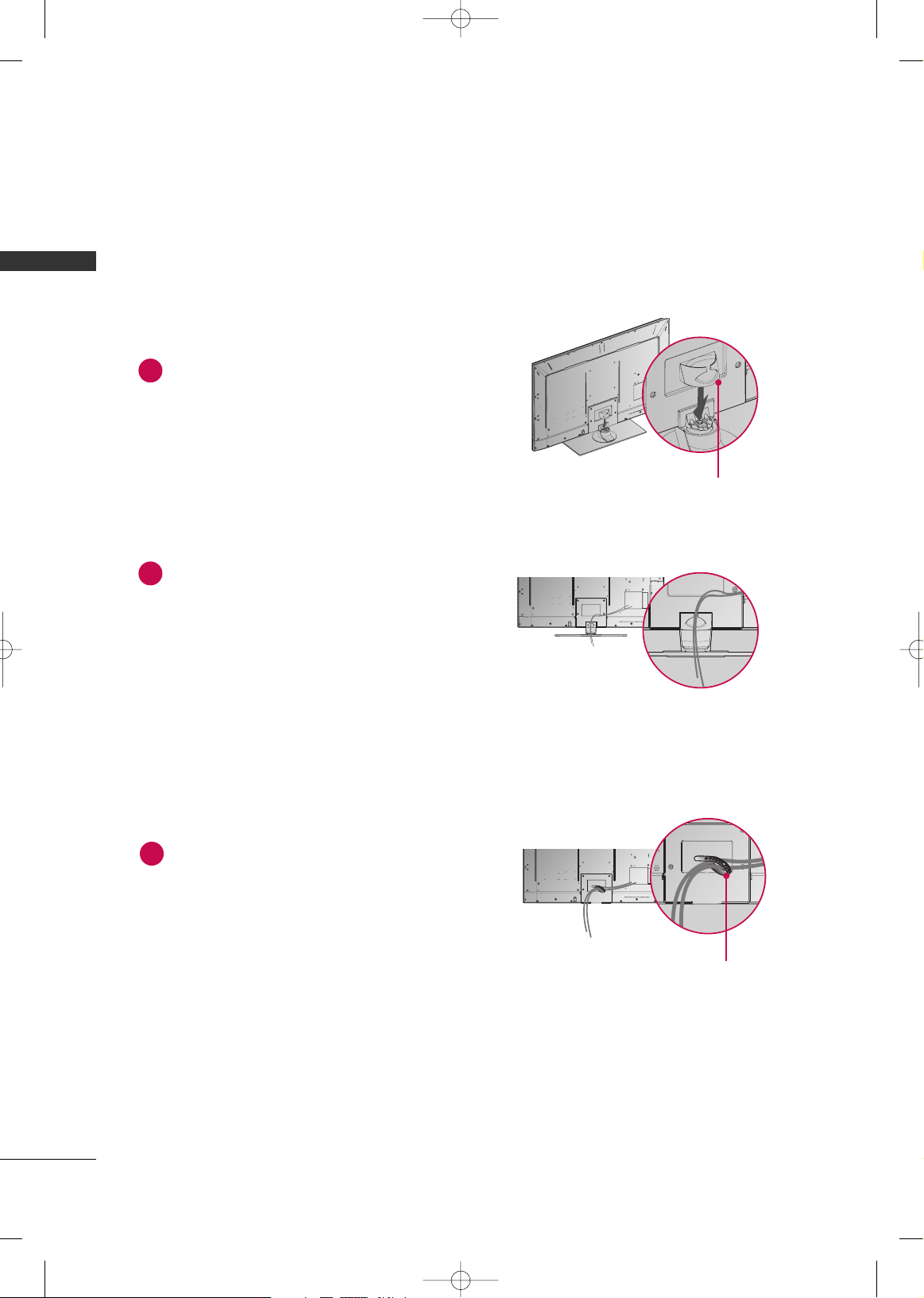
42/47SL90**
Install the CABLE MANAGEMENT CLIP as
shown.
1
Connect the cables as necessary.
To connect additional equipment, see the
EXTERNAL EQUIPMENT SETUP section.
Install CABLE HOLDER as shown and bundle
the cables.
1
Connect the cables as necessary.
To connect additional equipment, see the
EXTERNAL EQUIPMENT SETUP section.
2
FOR DESK-TYPE STAND
FOR WALL MOUNT
CABLE MANAGEMENT CLIP
CABLE HOLDER
MFL59166615-Edit1-en 12/2/09 3:38 PM Page 30
 Loading...