

Page 1

Please read this manual carefully before operating
your set.
Retain it for future reference.
Record model number and serial number of the set.
See the label attached on the back cover and quote
this information to your dealer
when you require service.
PLASMA TV
OWNER’S MANUAL
32PC5RV
www.lg.ca
Page 2

Page 3
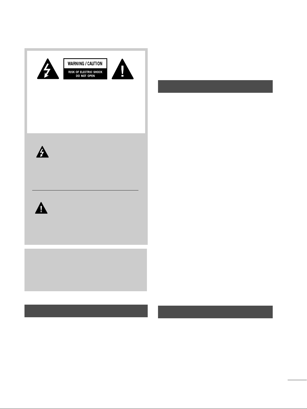
WARNING / CAUTION
1
WARNING / CAUTION
To prevent fire or shock hazards, do not expose
this product to rain or moisture.
FCC NOTICE
Class B digital device
This equipment has been tested and found to comply
with the limits for a Class B digital device, pursuant to
Part 15 of the FCC Rules. These limits are designed
to provide reasonable protection against harmful
interference in a residential installation. This equipment
generates, uses and can radiate radio frequency energy
and, if not installed and used in accordance with the
instructions, may cause harmful interference to radio
communications. However, there is no guarantee that
interference will not occur in a particular installation.
If this equipment does cause harmful interference to
radio or television reception, which can be determined
by turning the equipment off and on, the user is
encouraged to try to correct the interference by one
or more of the following measures:
- Reorient or relocate the receiving antenna.
- Increase the separation between the equipment and
receiver.
- Connect the equipment to an outlet on a circuit
different from that to which the receiver is connected.
- Consult the dealer or an experienced radio/TV
technician for help.
Any changes or modifications not expressly approved
by the party responsible for compliance could void
the user’s authority to operate the equipment.
CAUTION
Do not attempt to modify this product in any way
without written authorization from LG Electronics.
Unauthorized modification could void the user’s
authority to operate this product
The lightning flash with arrowhead
symbol, within an equilateral triangle, is
intended to alert the user to the presence
of uninsulated “dangerous voltage” within the
product’s enclosure that may be of sufficient
magnitude to constitute a risk of electric shock to
persons.
The exclamation point within an equilateral
triangle is intended to alert the user to
the presence of important operating and
maintenance (servicing) instructions in the literature accompanying the appliance.
TO REDUCE THE RISK OF ELECTRIC SHOCK
DO NOT REMOVE COVER (OR BACK). NO
USER SERVICEABLE PARTS INSIDE. REFER TO
QUALIFIED SERVICE PERSONNEL.
WARNING/CAUTION
TO REDUCE THE RISK OF FIRE AND ELECTRIC
SHOCK, DO NOT EXPOSE THIS PRODUCT TO
RAIN OR MOISTURE.
NOTE TO CABLE/TV INSTALLER
This reminder is provided to call the CATV system
installer’s attention to Article 820-40 of the National
Electric Code (U.S.A.). The code provides guidelines for
proper grounding and, in particular, specifies that the
cable ground shall be connected to the grounding system
of the building, as close to the point of the cable entry
as practical.
Page 4
IMPORTANT SAFETY INSTRUCTIONS
SAFETY INSTRUCTIONS
2
Important safety instructions shall be provided with each apparatus. This information shall be given in a separate
booklet or sheet, or be located before any operating instructions in an instruction for installation for use and
supplied with the apparatus.
This information shall be given in a language acceptable to the country where the apparatus is intended to be used.
The important safety instructions shall be entitled “Important Safety Instructions”. The following safety
instructions shall be included where applicable, and, when used, shall be verbatim as follows. Additional safety
information may be included by adding statements after the end of the following safety instruction list. At the
manufacturer’s option, a picture or drawing that illustrates the intent of a specific safety instruction may be
placed immediately adjacent to that safety instruction:
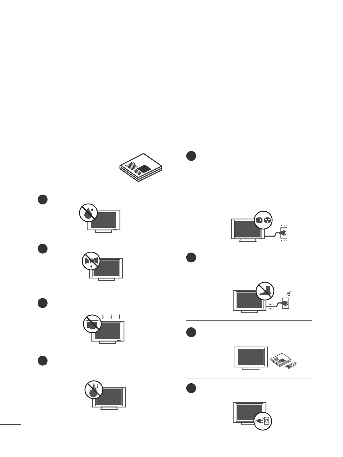
Read these instructions.
Keep these instructions.
Heed all warnings.
Follow all instructions.
Do not use this apparatus near water.
Clean only with dry cloth.
Do not block any ventilation openings. Install in
accordance with the manufacturer’s instructions.
Do not install near any heat sources such as
radiators, heat registers, stoves, or other apparatus
(including amplifiers)that produce heat.
Do not defeat the safety purpose of the polarized
or grounding-type plug. A polarized plug has
two blades with one wider than the other. A
grounding type plug has two blades and a third
grounding prong, The wide blade or the third
prong are provided for your safety. If the provided
plug does not fit into your outlet, consult an
electrician for replacement of the obsolete outlet.
Protect the power cord from being walked on
or pinched particularly at plugs, convenience
receptacles, and the point where they exit from
the apparatus.
Only use attachments/accessories specified by
the manufacturer.
Unplug this apparatus when unused for long
periods of time.
1
2
3
4
5
6
7
8
Page 5
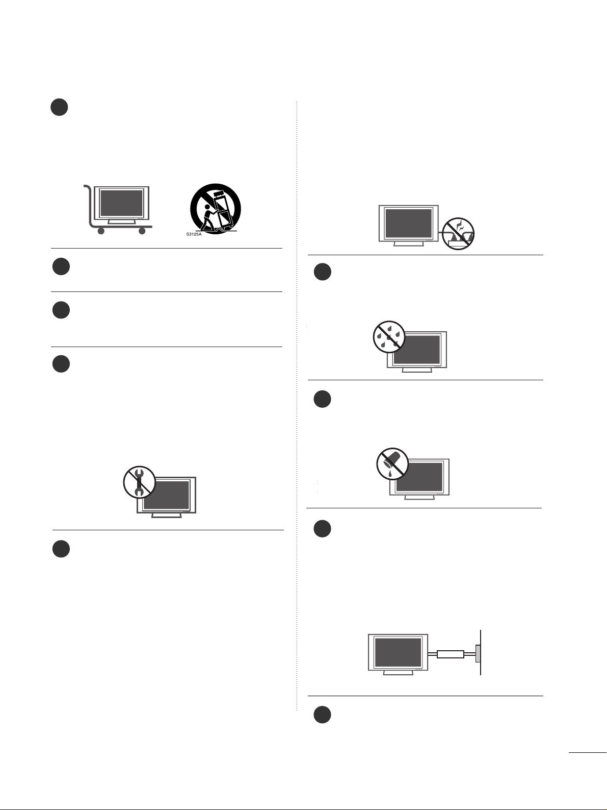
3
Use only with the cart, stand, tripod, bracket,
or table specified by the manufacturer, or sold
with the apparatus. When a cart is used, use
caution when moving the cart/apparatus
combination to avoid injury from tip-over.
Never touch this apparatus or antenna during
a thunder or lighting storm.
Do not allow a impact shock or any objects to
fall into the product, and do not drop onto the
screen with something.
Refer all servicing to qualified service personnel.
Servicing is required when the apparatus has
been damaged in any way, such as power-supply
cord or plug is damaged, liquid has been
spilled or objects have fallen into the apparatus,
the apparatus has exposed to rain or moisture,
does not operate normally, or has been
dropped.
CAUTION concerning the Power Cord :
Most appliances recommend they be placed
upon a dedicated circuit; that is, a single outlet
circuit which powers only that appliance and
has no additional outlets or branch circuits.
Check the specification page of this owner's
manual to be certain.
Do not overload wall outlets. Overloaded wall
outlets, loose or damaged wall outlets, extension
cords, frayed power cords, or damaged or
cracked wire insulation are dangerous. Any of
these conditions could result in electric shock
or fire. Periodically examine the cord of your
appliance, and if its appearance indicates damage or deterioration, unplug it, discontinue use
of the appliance, and have the cord replaced
with an exact replacement part by an authorized
servicer. Protect the power cord from physical
or mechanical abuse, such as being twisted,
kinked, pinched, closed in a door, or walked
upon. Pay particular attention to plugs, wall
outlets, and the point where the cord exits the
appliance.
Outdoor use marking :
WARNING - To reduce the risk of fire or elec-
tric shock, do not expose this appliance to rain
or moisture.
Wet Location Marking : Apparatus shall not be
exposed to dripping or splashing and no
objects filled with liquids, such as vases, shall
be placed on or over apparatus.
GGRROOUUNN DD IINN GG
Ensure that you connect the earth ground wire
to prevent possible electric shock. If grounding
methods are not possible, have a qualified
electrician install a separate circuit breaker.
Do not try to ground the unit by connecting it
to telephone wires, lightening rods, or gas pipes.
DDIISS CCOO NNNNEE CCTTII NNGG DDEEVVIICCEE FFRROOMM MMAAIINN SS
Mains plug is the disconnecting device. The
plug must remain readily operable.
9
12
10
11
13
14
15
16
17
Power
Supply
Short-circuit
Breaker
Page 6

CONTENTS
4
WARNING / CAUTION
. . . . . . . . . . . . . . . . . . . . . . . . . . . . 1
SAFETY INSTRUCTIONS
. . . . . . . . . . . . . . . . . . . . . . . . . . 2
FEATURES OF THIS TV
. . . . . . . . . . . . . . . . . . . . . . . . . . . . . 6
PREPARATION
Accessories
. . . . . . . . . . . . . . . . . . . . . . . . . . . . . . . . . . . . . . . . . . . . . . . . . . . . . .
7
Front Panel Information
. . . . . . . . . . . . . . . . . . . . . . . . . . . . . . . . . . . . .
8
Back Panel Information
. . . . . . . . . . . . . . . . . . . . . . . . . . . . . . . . . . . . . .
9
Stand Installation
. . . . . . . . . . . . . . . . . . . . . . . . . . . . . . . . . . . . . . . . . . . . 10
Back Cover for Wire Arrangement
. . . . . . . . . . . . . . . . . . . . . 10
Attaching the TV to a Wall
. . . . . . . . . . . . . . . . . . . . . . . . . . . . . . . . 11
Use Power Cord Holder
. . . . . . . . . . . . . . . . . . . . . . . . . . . . . . . . . . . . 11
Desktop Pedestal Installation
. . . . . . . . . . . . . . . . . . . . . . . . . . . .
12
Protection Cover
. . . . . . . . . . . . . . . . . . . . . . . . . . . . . . . . . . . . . . . . . . . . .
12
Antenna or Cable Connection
. . . . . . . . . . . . . . . . . . . . . . . . . .
13
EXTERNAL EQUIPMENT SETUP
HD Receiver Setup
. . . . . . . . . . . . . . . . . . . . . . . . . . . . . . . . . . . . . . . . . 14
DVD Setup
. . . . . . . . . . . . . . . . . . . . . . . . . . . . . . . . . . . . . . . . . . . . . . . . . . . . . . 17
VCR Setup
. . . . . . . . . . . . . . . . . . . . . . . . . . . . . . . . . . . . . . . . . . . . . . . . . . . . . 19
Other A/V Source Setup
. . . . . . . . . . . . . . . . . . . . . . . . . . . . . . . . .
21
PC Setup
. . . . . . . . . . . . . . . . . . . . . . . . . . . . . . . . . . . . . . . . . . . . . . . . . . . . . . . .
22
- Screen Setup for PC Mode . . . . . . . . . . . . . . . . . . . . . . . . 23
AV OUT Setup
. . . . . . . . . . . . . . . . . . . . . . . . . . . . . . . . . . . . . . . . . . . . . . . .
27
External Stereo . . . . . . . . . . . . . . . . . . . . . . . . . . . . . . . . . . . . . . . . . . . . . . . . 27
WATCHING TV / CHANNEL CONTROL
Remote Control Functions
. . . . . . . . . . . . . . . . . . . . . . . . . . . . . . . 28
Turning On TV
. . . . . . . . . . . . . . . . . . . . . . . . . . . . . . . . . . . . . . . . . . . . . . . .
30
Channel Selection
. . . . . . . . . . . . . . . . . . . . . . . . . . . . . . . . . . . . . . . . . . .
30
Volume Adjustment . . . . . . . . . . . . . . . . . . . . . . . . . . . . . . . . . . . . . . . . .
30
On Screen Menus Selection
. . . . . . . . . . . . . . . . . . . . . . . . . . . . .
31
Channel Setup
- Auto Scan (Auto Tuning)
. . . . . . . . . . . . . . . . . . . . . . . . . . .
32
- Add / Delete Channel (Manual Tuning)
. . . . . .
33
Fine Tuning Adjustment
. . . . . . . . . . . . . . . . . . . . . . . . . . . . . . . . . . . 34
Favorite Channels Setup
. . . . . . . . . . . . . . . . . . . . . . . . . . . . . . . . . . 35
SimpLink
. . . . . . . . . . . . . . . . . . . . . . . . . . . . . . . . . . . . . . . . . . . . . . . . . . . . . . . . .
36
Key Lock . . . . . . . . . . . . . . . . . . . . . . . . . . . . . . . . . . . . . . . . . . . . . . . . . . . . . . . . . 38
Factory Reset
. . . . . . . . . . . . . . . . . . . . . . . . . . . . . . . . . . . . . . . . . . . . . . . . . .
39
PICTURE CONTROL
PIP/Double Window
. . . . . . . . . . . . . . . . . . . . . . . . . . . . . . . . . . . . . . . .
40
Picture Size (Aspect Ratio) Control
. . . . . . . . . . . . . . . . . . 41
Preset Picture Settings
- Picture Mode - Preset
. . . . . . . . . . . . . . . . . . . . . . . . . . . . . . . 42
- Color Tone - Preset
. . . . . . . . . . . . . . . . . . . . . . . . . . . . . . . . . . . 43
Manual Picture Adjustment
- Picture Mode - User Mode
. . . . . . . . . . . . . . . . . . . . . . . . 44
- Color Tone - User Mode
. . . . . . . . . . . . . . . . . . . . . . . . . . . 45
XD - Picture Improvement Technology
. . . . . . . . . . . . .
46
XD Demo
. . . . . . . . . . . . . . . . . . . . . . . . . . . . . . . . . . . . . . . . . . . . . . . . . . . . . . . 47
Advanced - Cinema 3:2 Pull Down Mode
. . . . . . . . . 48
Advanced - Black (Darkness) Level
. . . . . . . . . . . . . . . . . . . 49
Image Sticking Minimization (ISM) Method
. . . . . . 50
Low - Power Picture Mode
. . . . . . . . . . . . . . . . . . . . . . . . . . . . . . 51
Picture Reset
. . . . . . . . . . . . . . . . . . . . . . . . . . . . . . . . . . . . . . . . . . . . . . . . . 52
SOUND & LANGUAGE CONTROL
Preset Sound Setting (Sound Mode)
. . . . . . . . . . . . . . . .
53
Sound Frequency Adjustment
. . . . . . . . . . . . . . . . . . . . . . . . . .
54
Auto Volume Leveler
. . . . . . . . . . . . . . . . . . . . . . . . . . . . . . . . . . . . . . . .
55
Balance Adjustment
. . . . . . . . . . . . . . . . . . . . . . . . . . . . . . . . . . . . . . . . 56
TV Speakers On/Off Setup
. . . . . . . . . . . . . . . . . . . . . . . . . . . . . . 57
Stereo/SAP Broadcasts Setup
. . . . . . . . . . . . . . . . . . . . . . . . . .
58
On-Screen Menus Language Selection
. . . . . . . . . . . . . .
59
Caption/Text
. . . . . . . . . . . . . . . . . . . . . . . . . . . . . . . . . . . . . . . . . . . . . . . . . . 60
Page 7

5
TIME SETTING
Clock Setting
- Auto Clock Setup
. . . . . . . . . . . . . . . . . . . . . . . . . . . . . . . . . . . . 61
- Manual Clock Setup . . . . . . . . . . . . . . . . . . . . . . . . . . . . . . . . .
62
Auto On/Off Time Setting
. . . . . . . . . . . . . . . . . . . . . . . . . . . . . . 63
Sleep Time Setting
. . . . . . . . . . . . . . . . . . . . . . . . . . . . . . . . . . . . . . . . . .
64
Auto Shut-off Setting . . . . . . . . . . . . . . . . . . . . . . . . . . . . . . . . . . . . . . .
65
PARENTAL CONTROL / RATINGS
Set Password & Lock System
. . . . . . . . . . . . . . . . . . . . . . . . . . .
66
Movie & TV Rating
. . . . . . . . . . . . . . . . . . . . . . . . . . . . . . . . . . . . . . . . . 68
Age Block
. . . . . . . . . . . . . . . . . . . . . . . . . . . . . . . . . . . . . . . . . . . . . . . . . . . . . . .
69
Content Block
. . . . . . . . . . . . . . . . . . . . . . . . . . . . . . . . . . . . . . . . . . . . . . . . . 70
Aux. Block
. . . . . . . . . . . . . . . . . . . . . . . . . . . . . . . . . . . . . . . . . . . . . . . . . . . . . . .
70
- Canadian . . . . . . . . . . . . . . . . . . . . . . . . . . . . . . . . . . . . . . . . . . . . . . . . . . 71
APPENDIX
Troubleshooting
. . . . . . . . . . . . . . . . . . . . . . . . . . . . . . . . . . . . . . . . . . . . . .
72
Maintenance
. . . . . . . . . . . . . . . . . . . . . . . . . . . . . . . . . . . . . . . . . . . . . . . . . . .
74
Product Specifications
. . . . . . . . . . . . . . . . . . . . . . . . . . . . . . . . . . . . .
75
Page 8

FEATURES OF THIS TV
6
LG's own special digital image generator, consisting
of a full digital image processor, six different main
picture quality factors.
With HDMI CEC support of LG’s audio/video device
connected to the HDMI (high-definition multimedia
interface), LG TV with this logo works easily with one
remote control.
HDMI
TM
, the HDMI logo and High-Definition
Multimedia Interface are trademarks or registered
trademarks of HDMI Licensing."
Page 9
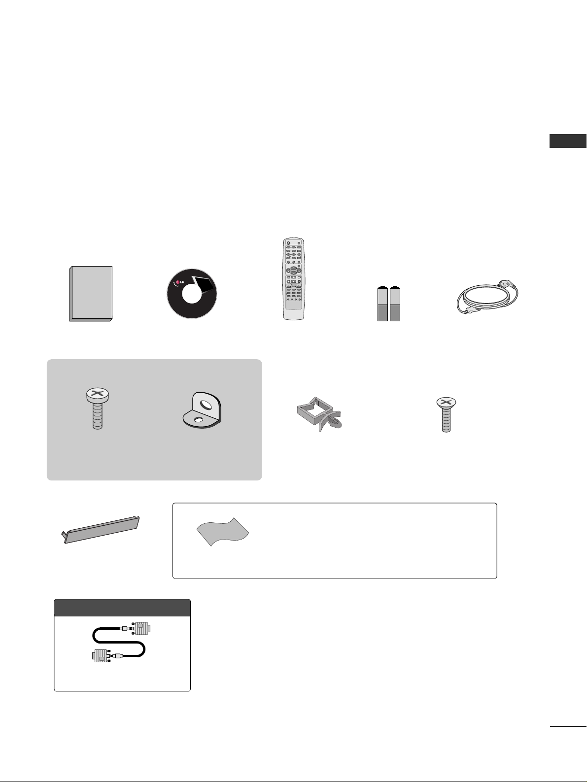
ACCESSORIES
PREPARATION
7
PREPARATION
Ensure that the following accessories are included with your product. If an accessory is missing, please contact
the dealer where you purchased the product.
User must use shielded signal interface cables (D-sub 15 pin cable) with ferrite cores to maintain standard
compliance for the product.
The accessories can be different from the figures shown here.
Protection Cover
(Refer to p.12)
OOppttiioonn EExxttrraass
Power Cord Holder
(Refer to p.11)
4-Bolts for stand assembly
(Refer to p.10)
* Slightly wipe stained spot on the exterior only with the polishing cloth
for the product exterior if there is stain or fingerprint on surface of the
exterior.
* Do not wipe roughly when removing stain. Please be cautions of that
excessive pressure may cause scratch or discoloration.
Polishing Cloth
Copyright© 2007 LGE,
All Rights Reserved.
D-sub 15 pin Cable
1.5V 1.5V
Owner’s Manual Power Cord
Remote Control
Batteries
ENTER
CH
VOL
CH
VOL
FAV
REVIEW
PIP INPUT
0
INPUT
MUTE
MENU
EXIT
RATIO
1
23
4
56
7
89
POWER
TV
CH EDIT
PIP CH - PIP CH +
SLEEP
CAPTION
MTS
SIZE
POSITION
PIP
CD Manual
This feature is not available for all models
2- TV Bracket Bolts
(Refer to p.11)
2- TV Brackets,
2- Wall Brackets
(Refer to p.11)
Page 10
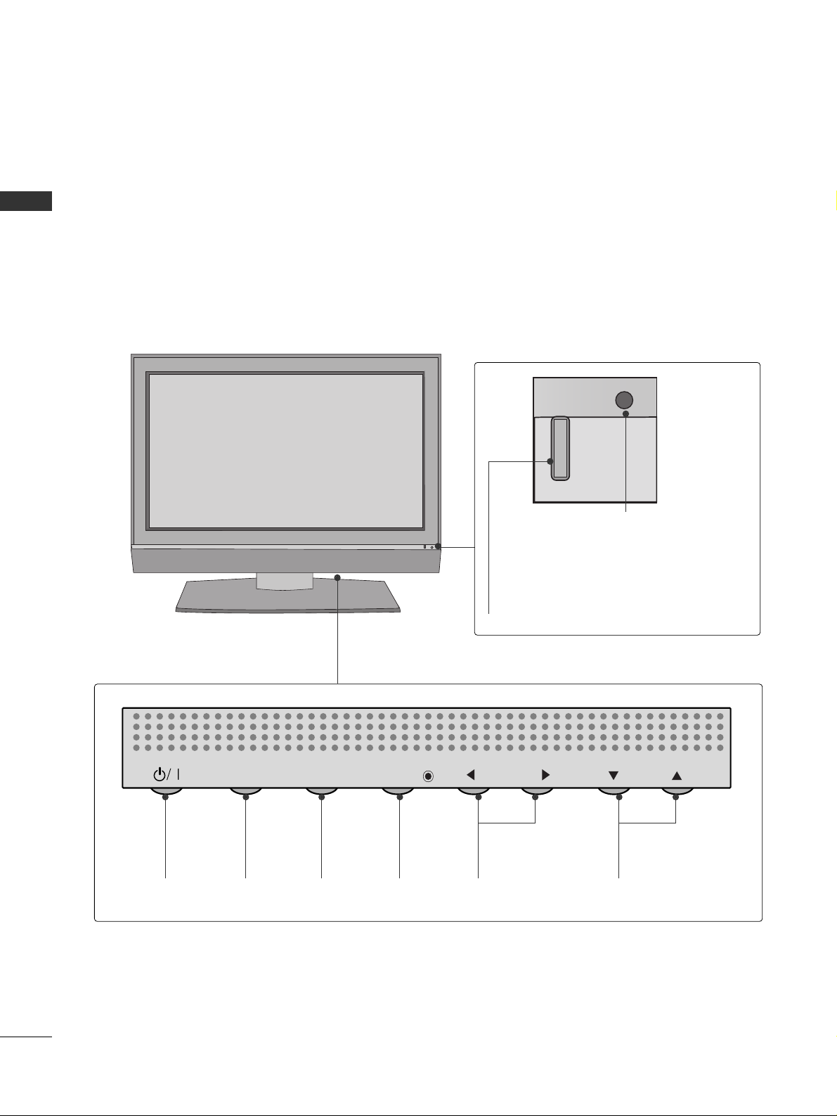
FRONT PANEL INFORMATION
PREPARATION
8
PREPARATION
■
Here shown may be somewhat different from your TV.
■
NOTE: If your product has a protection tape attached, remove the tape.
And then wipe the product with a cloth (If a polishing cloth is included with your product, use it).
Power/Standby Indicator
Illuminates red in standby mode.
Illuminates green when the set is
switched on.
Remote Control Sensor
POWER
Button
INPUT
Button
MENU
Button
ENTER
Button
VOLUME
(
FF,GG
)Buttons
CHANNEL
(
EE,DD
)Buttons
INPUT
MENU
ENTER
VOL
CH
Page 11

BACK PANEL INFORMATION
9
PREPARATION
8
COMPONENT IN 1/2
Connect a component video/audio device to
these jacks.
VARIABLE OUT
Connect an external amplifier or add a subwoofer
to your surround sound system.
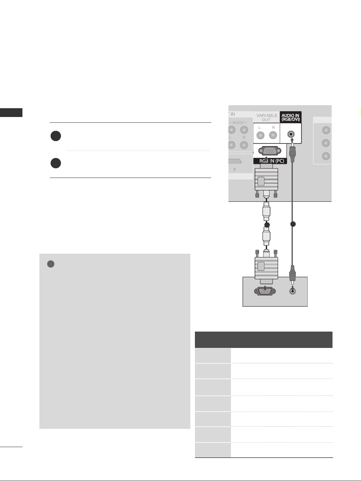
RGB IN (PC)
Connect the output from a PC.
AUDIO IN (RGB/DVI)
Connect the audio from a PC or DTV.
AV OUT
Connect second TV or monitor to the AV OUT
socket on the set
AV IN
Connect audio/video output from an external
device to these jacks.
HDMI/DVI IN 1, HDMI IN 2
Connect a HDMI signal to HDMI IN.
Or DVI(VIDEO)signal to HDMI/DVI port with DVI
to HDMI cable.
ANTENNA IN
Connect over-the-air signals to this jack.
Power Cord Socket
This TV operates on an AC power. The voltage is
indicated on the Specifications page. Never
attempt to operate the TV on DC power.
1
2
3
4
5
6
7
2
6
3
3
1
4
5
7
8
Page 12

STAND INSTALLATION
PREPARATION
10
PREPARATION
Carefully place the product screen side down on
a cushioned surface that will protect product and
screen from damage.
Assemble the product stand with the product as
shown.
Install the 4 bolts securely, in the back of the
product in the holes provided.
1
2
3
BACK COVER FOR WIRE ARRANGEMENT
Arrange the cables as shown picture.
Page 13
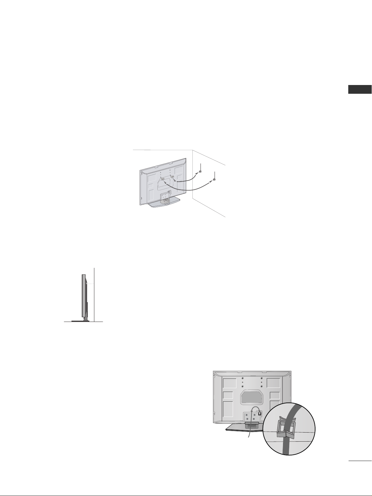
ATTACHING THE TV TO A WALL
11
PREPARATION
USE POWER CORD HOLDER
After connecting the power cord to the AC input
terminal, remove the bolt at the hole on the back
cover and fix the power cord at the rear side of the
TV by using the bracket for fixing the power cord.
We recommend that you set up the TV close to a wall so it cannot fall over if pushed backwards.
Additionally, we recommend that the TV be attached to a wall so it cannot be pulled in a forward direction,
potentially causing injury or damaging the product.
Caution: Please make sure that children don’t climb on or hang from the TV.
■
Insert the eye-bolts or TV brackets and bolts to tighten the product to the wall as shown in the picture.
*If your product has the bolts in the eye-bolts position before inserting the bolts, loosen the bolts.
Secure the wall brackets with the bolts (not provided as parts of the product, must purchase separately) to
the wall. Match the height of the bracket that is mounted on the wall to the holes in the product.
Ensure the eye-bolts or brackets are tightened securely.
■
Use a sturdy rope (not provided as parts of the product, must purchase separately) to tie the product. It is safer to tie the rope so it
becomes horizontal between the wall and the product.
■
This feature is not available for all models.
■
Here shown may be somewhat different from your TV.
Page 14
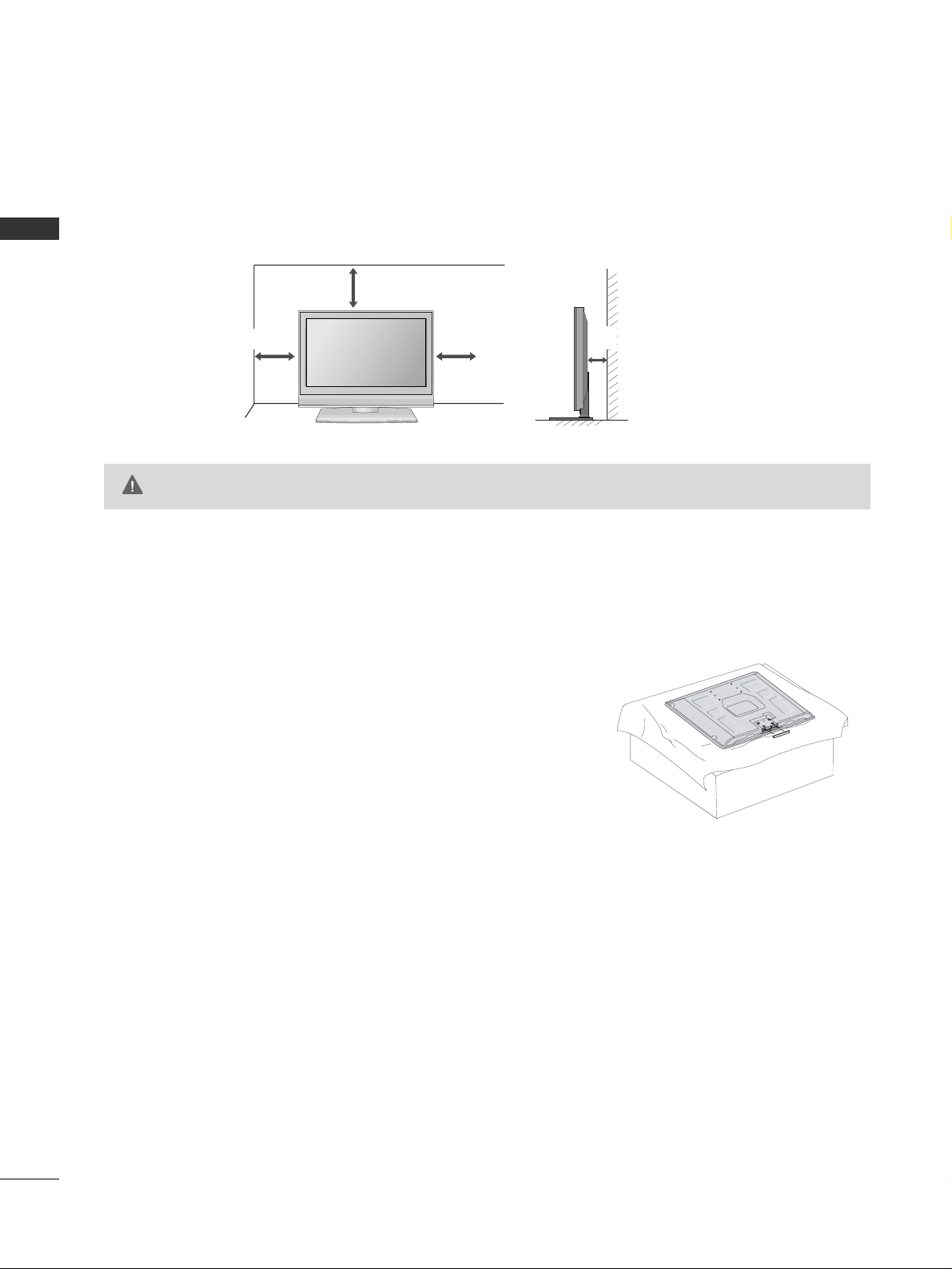
DESKTOP PEDESTAL INSTALLATION
PREPARATION
12
PREPARATION
For proper ventilation, allow a clearance of 4 inches on all four sides from the wall.
PROTECTION COVER
When installing the wall-mounted unit, use the protection
cover for desk-type stand installation.
4 inches
4 inches
4 inches
GG
Ensure adequate ventilation by following the clearance recommendations.
CAUTION
4 inches
Page 15

ANTENNA OR CABLE CONNECTION
13
PREPARATION
Wall Antenna Socket or Outdoor Antenna without a Cable Box Connections.
For optimum picture quality, adjust antenna direction if needed.
Multi-family Dwellings/Apartments
(Connect to wall antenna socket)
Single-family Dwellings /Houses
(Connect to wall jack for outdoor antenna)
Outdoor
Antenna
(VHF, UHF)
Wall
Antenna
Socket
RF Coaxial Wire (75 ohm)
Bronze Wire
Be careful not to bend the bronze
wire when connecting the antenna.
The TV will let you know when the analog and cable scans are complete.
NOTE
!
Antenna
UHF
Signal
Amplifier
VHF
■
To improve the picture quality in a poor signal area, please purchase a signal amplifier and install properly.
■
If the antenna needs to be split for two TV’s, install a 2-Way Signal Splitter.
■
If the antenna is not installed properly, contact your dealer for assistance.
Page 16

EXTERNAL EQUIPMENT SETUP
14
EXTERNAL EQUIPMENT SETUP
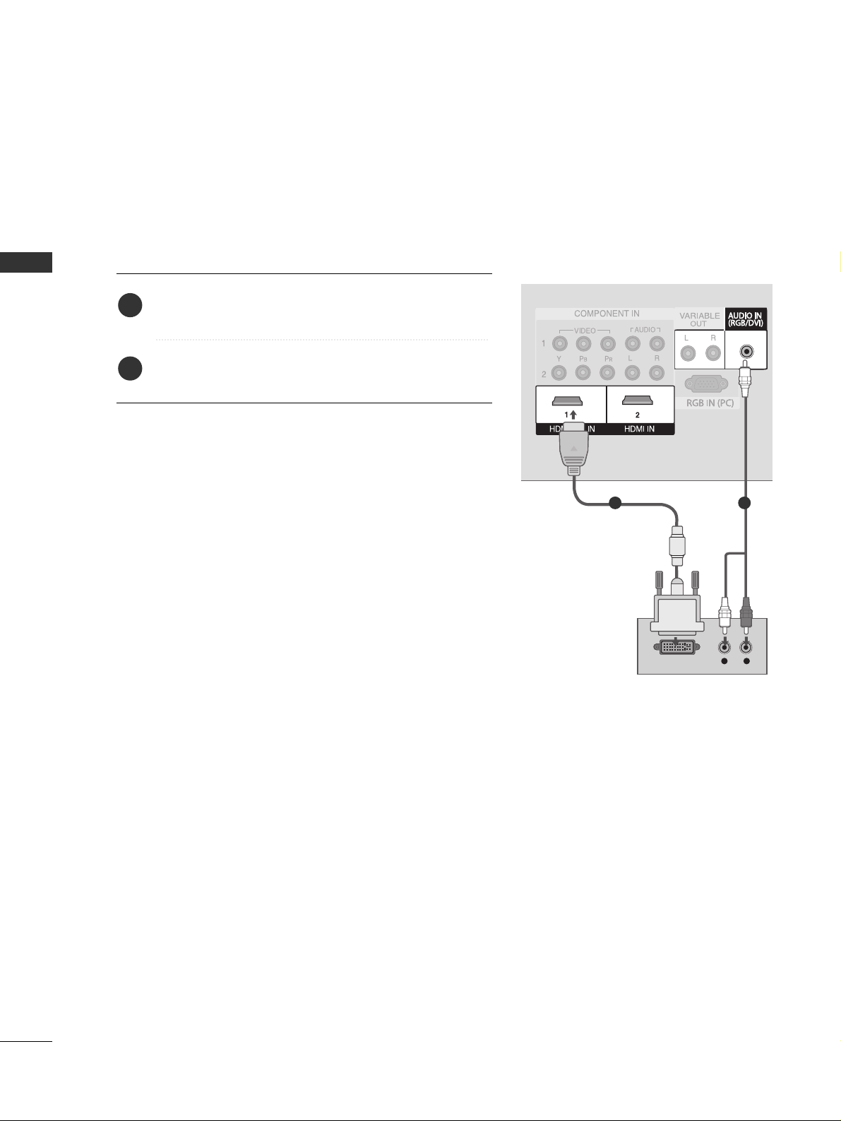
HD RECEIVER SETUP
Y L RPBP
R
When connecting with a component cable
1. How to connect
Connect the video outputs (Y, P
B, P
R
)
of the digital set
top box to the
CC OOMMPPOONNEENN TT IINN VV IIDDEEOO 11
jacks on
the set. Match the jack colors
(Y = green, P
B = blue, and PR
= red).
Connect the audio output of the digital set-top box to
the
CC OOMMPPOONNEENN TT IINN AAUUDDII OO 11
jacks on the set.
2
1
2. How to use
■
Turn on the digital set-top box.
(
Refer to the owner’s manual for the digital set-top box.
)
■
Select
CC oo mmppoo nn eenn tt 11
input source with using the
IINNPP UU TT
button on the remote control.
■
If connected to
CC OOMMPPOONNEENNTT IINN22
input, select
CC oo mmppoo nn eenn tt 22
input source.
1 2
■
To prevent the equipment damage, never plug in any power cords until you have finished connecting all equipment.
Signal
480i
480p
720p
10 8 0 i
Component 1, 2
Yes
Yes
Yes
Yes
HDMI1/DVI,
HDMI2
No
Yes
Yes
Yes
Y, C
B/
PB, C
R/P
R
Horizontal Vertical
Frequency(KHz)Frequency(Hz
)
15.73 59.94
15.75 60.00
31.47 59.94
31.5 60.00
44.96 59.94
45.00 60.00
33.72 59.94
33.75 60.00
Resolution
1280 x 720p
1920 x 1080i
720 x 480i
720 x 480p
Page 17
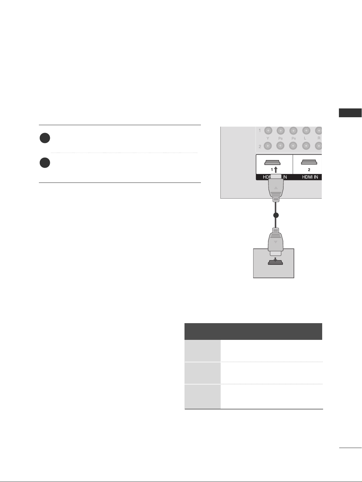
EXTERNAL EQUIPMENT SETUP
15
When connecting with a HDMI cable
Connect the digital set-top box to
HHDDMM II //DDVVII II NN 11
or
HHDDMM II IINN 22
jack on the set.
No separated audio connection is necessary.
HDMI supports both audio and video.
1. How to connect
2. How to use
■
Turn on the digital set-top box.
(
Refer to the owner’s manual for the digital set-top box.
)
■
Select
HHDDMM II 11
or
HHDDMM II 22
input source with using the
IINNPP UU TT
button on the remote control.
2
1
HDMI-DTV OUTPUT
1
Resolution
720x480p
1280x720p
1920x1080i
Supported Display Resolution (HDMI-DTV mode)
Horizontal Vertical
Frequency(KHz) Frequency(Hz)
31.47 59.94
31.50 60.00
44.96 59.94
45.00 60.00
33.72 59.94
33.75 60.00
Page 18
EXTERNAL EQUIPMENT SETUP
16
EXTERNAL EQUIPMENT SETUP
When connecting with a HDMI to DVI cable
L R
DVI-DTV OUTPUT
1 2
Connect the DVI output of the digital set-top box to the
HHDDMM II //DDVVII IINN 11
jack on the set.
Connect the audio output of the digital set-top box to
the
AAUUDDII OO IINN
((
RRGGBB// DD VV II
))
jack on the set.
1. How to connect
2. How to use
■
Turn on the digital set-top box. (Refer to the owner’s manual for the digital set-top box.
)
■
Select
HHDDMM II11
input source with using the
IINNPP UU TT
button
on the remote control.
2
1
Page 19
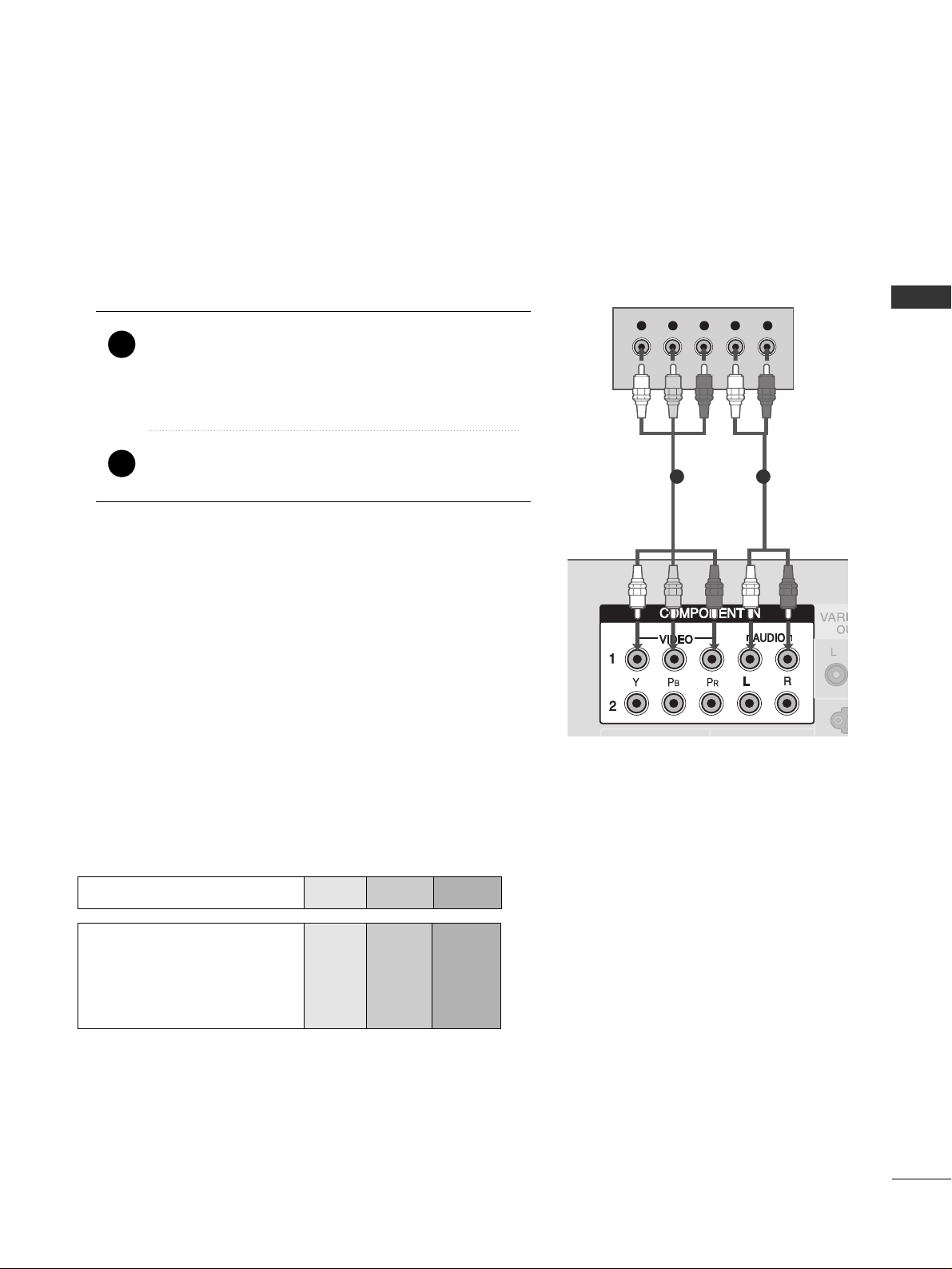
DVD SETUP
17
EXTERNAL EQUIPMENT SETUP
When connecting with a component cable
Y L RPBP
R
Component Input ports
To get better picture quality, connect a DVD player to the component input ports as shown below.
Component ports on the TV
YPB PR
Video output ports
on DVD player
Y
Y
Y
Y
PB
B-Y
Cb
Pb
P
R
R-Y
Cr
Pr
Connect the video outputs (Y, P
B, PR
)
of the DVD to
the
CC OOMMPPOONNEENN TT IINN VVIIDDEE OO 11
jacks on the set.
Match the jack colors
(
Y = green, P
B = blue, and P
R = red
)
.
Connect the audio outputs of the DVD to the
CC OOMMPPOONNEENN TT IINN AAUUDDII OO 11
jacks on the set.
1. How to connect
2. How to use
■
Turn on the DVD player, insert a DVD.
■
Select
CC oo mmppoo nn eenn tt 11
input source with using the
IINNPP UU TT
button on the remote control.
■
If connected to
CC OOMMPPOONNEENNTT IINN 22
input, select
CC oo mmppoo nn eenn tt 22
input source.
■
Refer to the DVD player's manual for operating instructions.
2
1
1 2
Page 20

EXTERNAL EQUIPMENT SETUP
18
EXTERNAL EQUIPMENT SETUP
HDMI-DVD OUTPUT
When connecting HDMI cable
Connect the HDMI output of the DVD to the
HHDDMM II //DDVVII II NN 11
or
HHDDMM II IINN 22
jack on the set.
No separated audio connection is necessary.
HDMI supports both audio and video.
1. How to connect
2. How to use
■
Select
HHDDMM II 11 orHHDDMM II22
input source with using the
IINNPP UU TT
button on the remote control.
■
Refer to the DVD player's manual for operating instructions.
2
1
1
Page 21

VCR SETUP
19
EXTERNAL EQUIPMENT SETUP
When connecting with an antenna
■
To avoid picture noise (interference), leave an adequate distance between the VCR and TV
■
If the 4:3 picture format is used; the fixed images on the sides of the screen may remain visible on the
screen. This phenomenon is common to all manufactures and in consequence the manufactures warranty
does not cover the product bearing this phenomenon.
L/MONOL/MONO
R
AUDIOAUDIO
VIVIDEO
L R
S-VIDEO VIDEO
OUTPUT
SWITCH
ANT IN
ANT OUT
Wall Jack
Antenna
Connect the RF antenna out socket of the VCR to the
AANN TT EE NNNNAA IINN
socket on the set.
Connect the antenna cable to the RF antenna in socket of the VCR.
1. How to connect
■
Set VCR output switch to 3 or 4 and then tune TV to the same channel number.
■
Insert a video tape into the VCR and press PLAY on the VCR. (Refer to the VCR owner’s manual.
)
2. How to use
2
1
2
1
Page 22
EXTERNAL EQUIPMENT SETUP
20
EXTERNAL EQUIPMENT SETUP
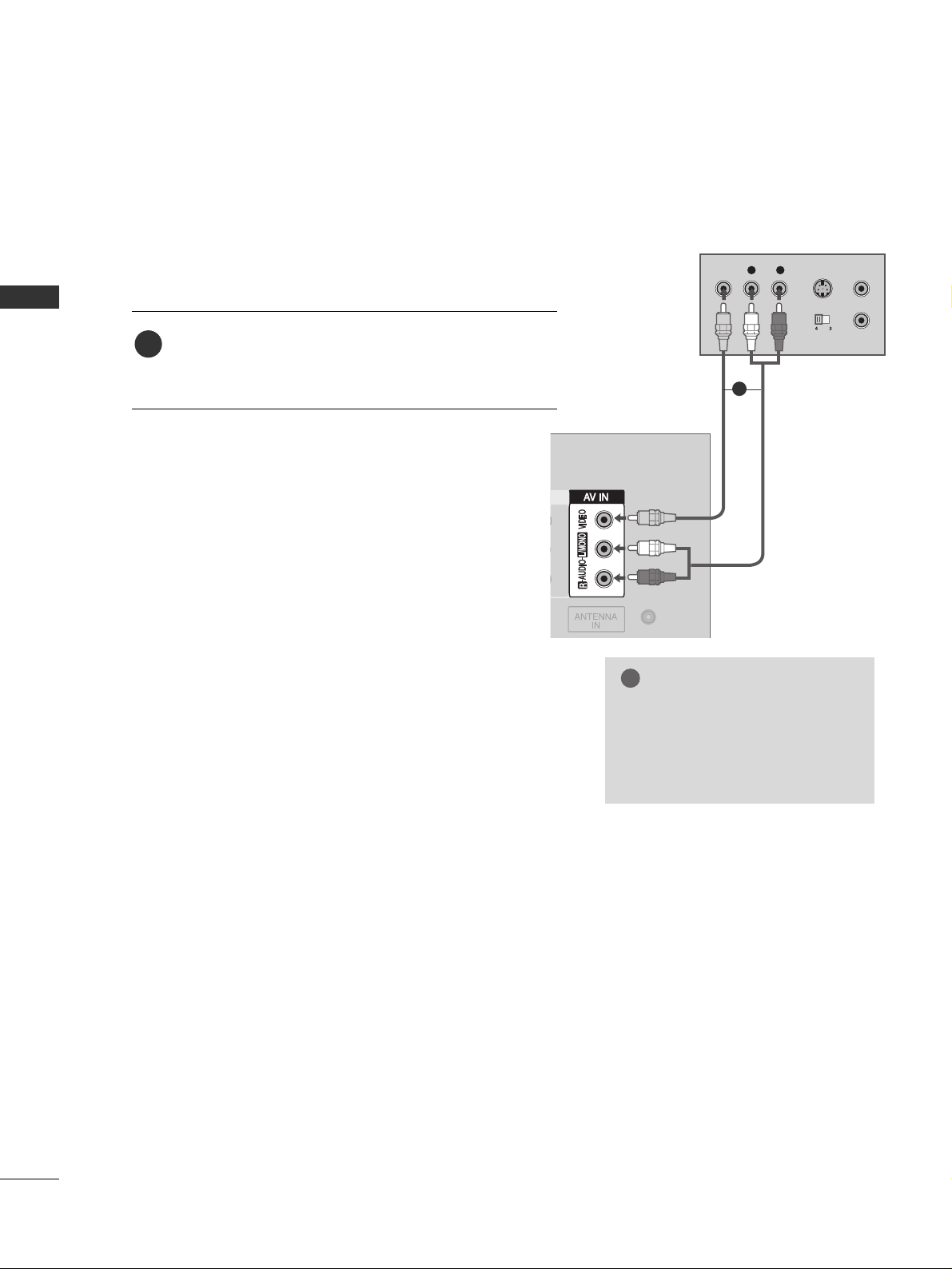
When connecting with a RCA cable
L/MONO
R
AUDIO
VIDEO
L R
S-VIDEOVIDEO
OUTPUT
SWITCH
ANT IN
ANT OUT
Connect the
AAUUDDIIOO/VVIIDDEEOO
jacks between TV and
VCR. Match the jack colors (Video = yellow, Audio Left
= white, and Audio Right = red)
1. How to connect
2. How to use
■
Insert a video tape into the VCR and press PLAY on
the VCR. (Refer to the VCR owner’s manual.
)
■
Select
AA VV
input source with using the
IINNPP UU TT
button
on the remote control.
1
GG
If you have a mono VCR, connect the audio cable from the
VCR to the
AAUUDDIIOO
LL//MM OO NN OO
jack of the set.
NOTE
!
1
Page 23
OTHER A/V SOURCE SETUP
21
EXTERNAL EQUIPMENT SETUP
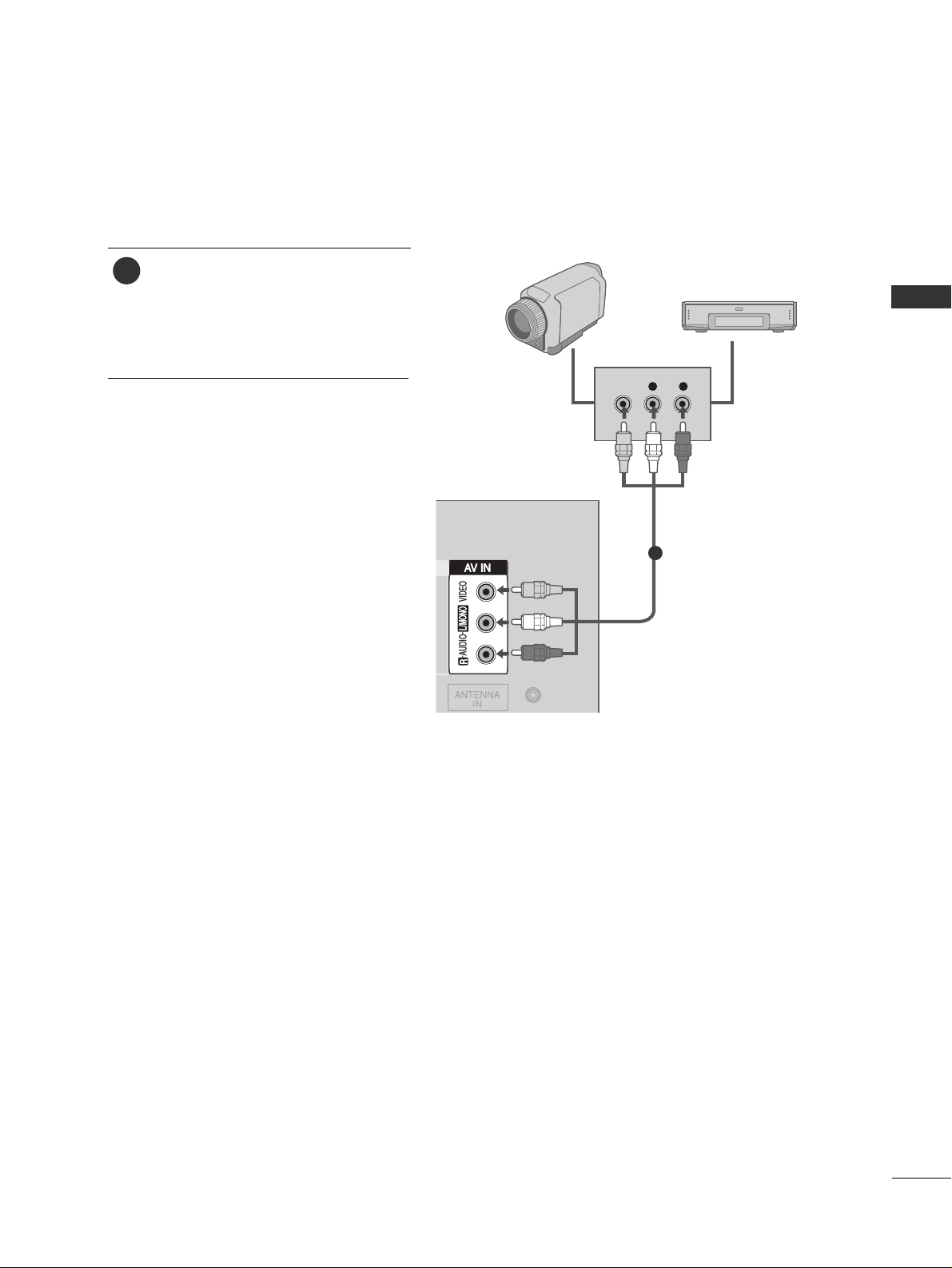
Connect the
AAUUDDIIOO/VVIIDDEEOO
jacks
between TV and external equipment.
Match the jack colors
.
(
Video = yellow, Audio Left = white, and
Audio Right = red
)
1. How to connect
2. How to use
■
Select
AAVV
input source with using the
IINNPP UU TT
button on the remote control.
■
Operate the corresponding external
equipment.
L R
VIDEO
Camcorder
Video Game Set
1
1
Page 24
EXTERNAL EQUIPMENT SETUP
22
EXTERNAL EQUIPMENT SETUP
PC SETUP
This TV provides Plug and Play capability, meaning that the PC adjusts automatically to the TV's settings.
When connecting with a D-sub 15 pin cable
L/MONO
R
AUDIO
VIDEO
AV OUT
RGB OUTPUT
AUDIO
Connect the RGB output of the PC to the
RRGGBB IINN
((
PP CC
))
jack on the set.
Connect the PC audio output to the
AAUUDDII OO II NN
((
RRGGBB// DD VV II
))
jack on the set.
1. How to connect
2. How to use
■
Turn on the PC and the set.
■
Select
RRGGBB PP CC
input source with using the
IINNPP UU TT
button
on the remote control.
■
This TV doesn’t support DVI-PC mode.
2
1
1
2
Resolution
640x350
720x400
640x480
848x480
852x480
800x600
1024x768
Supported Display Resolution (RGB PC mode)
Horizontal Vertical
Frequency(KHz) Frequency(Hz)
31.468 70.09
31.469 70.08
31.469 59.94
31.5 60.00
31.5 60.00
37.879 60.31
48.363 60.00
NOTE
!
GG
To get the the best picture quality, adjust the PC
graphics card to 852x480, 60Hz.
GG
Check the image on your TV. There may be noise
associated with the resolution, vertical pattern,
contrast or brightness in PC mode. If noise is
present, change the PC output to another resolution, change the refresh rate to another rate or
adjust the brightness and contrast on the Picture
menu until the picture is clear. If the refresh rate of
the PC graphic card can not be changed, change
the PC graphic card or consult the manufacturer
of the PC graphic card.
GG
Avoid keeping a fixed image on the screen for a
long period of time. The fixed image may become
permanently imprinted on the screen.
GG
The synchronization input form for Horizontal and
Vertical frequencies is separate.
Page 25

SCREEN SETUP FOR PC MODE
23
EXTERNAL EQUIPMENT SETUP
Automatically adjusts picture position and minimizes image
shaking.
Although the image is still not correct, your set is functioning properly but needs further adjustment.
Auto Configure (RGB PC mode only)
Press the
MMEENNUU
button and then use
DD
or
EE
button to
select the
PP iiccttuurree
menu.
Press the
GG
button and then use
DD
or
EE
button to
select
SS cc rr eeeenn
.
Press the
GG
button and then use
DD
or
EE
button to
select
AAuu ttoo ccoo nn ffii gg ..
.
Press the
GG
button to start
AAuu ttoo ccoo nn ffii gg ..
.
• When
AAuu ttoo ccoo nn ffii gg ..
has finished,
OO KK
will be shown
on screen.
• If the position of the image is still not correct, try
Auto adjustment again.
If picture needs to be adjusted more after Auto adjustment in RGB PC, you can adjust the
MM aannuuaa ll ccoonnff iigg ..
.
Press
EEXXIITT
button to return to TV viewing or press
MM EENNUU
button to return to the previous menu.
1
2
3
4
5
6
1
3 4
Picture Mode
Color Temperature
XD
Advanced
Aspect Ratio
Picture Reset
Screen
XD Demo
Picture
Screen
To Set
2
Picture
To Set
DE F G
MENU
DE F G
MENU
DE F G
MENU
Picture Mode
Color Temperature
XD
Advanced
Aspect Ratio
Picture Reset
Screen G
XD Demo
Auto config.
G
Manual Config.
VGA Mode
Reset
POWER
INPUT
1
4
7
RATIO
VOL
TV
23
56
89
MUTE
0
MENU
EXIT
ENTER
CH
VOL
CH
Page 26

EXTERNAL EQUIPMENT SETUP
24
EXTERNAL EQUIPMENT SETUP
Adjustment for screen Phase, Clock, Position
Press the
MMEENNUU
button and then use
DD
or
EE
button to
select the
PP iiccttuurree
menu.
Press the
GG
button and then use
DD
or
EE
button to
select
SS cc rr eeeenn
.
Press the
GG
button and then use
DD
or
EE
button to
select
MM aannuuaa ll ccoonnff iigg ..
.
Press the
GG
button and then use
DD
or
EE
button to
select
PP hh aass ee,, CCll oocc kk ,, HH--ppooss iittiioonn
or
VV--ppoo ssiittiioo nn
.
Press the
FF
or GGbutton to make appropriate adjust-
ments.
Press
EEXXIITT
button to return to TV viewing or press
MM EENNUU
button to return to the previous menu.
1
2
3
4
5
6
1
3 4 5
Picture Mode
Color Temperature
XD
Advanced
Aspect Ratio
Picture Reset
Screen
XD Demo
Picture
Screen
Phase 50
Clock 0
H-Position 0
V-Position 0
2
Picture
To Set
DE F G
MENU
DE F G
MENU
DE F G
MENU
If the picture isn’t clear after auto adjustment and especially
if characters are still trembling, adjust the picture phase
manually.
To correct the screen size, adjust Clock.
This function works in the following mode : RGB PC, COM-
PONENT (480i/480p/720p/1080i), HDMI (480p/720p/1080i).
It’s not available to use Phase, Clock function in COMPO-
NENT (480i/480p/720p/1080i), HDMI (480p/720p/1080i).
CCll oo cc kk
This function is to minimize any vertical bars or
stripes visible on the screen background. And the
horizontal screen size will also change.
PP hh aass ee
This function allows you to remove any horizontal
noise and clear or sharpen the image of characters.
Picture Mode
Color Temperature
XD
Advanced
Aspect Ratio
Picture Reset
Screen G
XD Demo
Auto Config.
Manual Config.
G
VGA Mode
Reset
ENTER
CH
VOL
CH
VOL
MENU
EXIT
POWER
TV
0
INPUT
MUTE
RATIO
1
23
4
56
7
89
Page 27

25
EXTERNAL EQUIPMENT SETUP
To see a normal picture, match the resolution of RGB mode
and selection of VGA mode.
This function works in the following mode: RGB PC mode.
Selecting Wide VGA mode
Press the
MM EENNUU
button and then use
DD
or
EE
button
to select the
PP iicc ttuurree
menu.
Press the
GG
button and then use
DD
or
EE
button to
select
SS cc rree eenn
.
Press the
GG
button and then use
DD
or
EE
button to
select
VVGGAA MMoodd ee
.
Press the
GG
button and then use
DD
or
EE
button to
select the desired VGA resolution.
Press
EEXXIITT
button to return to TV viewing or press
MM EENNUU
button to return to the previous menu.
1
2
3
4
5
1
3 4
Picture Mode
Color Temperature
XD
Advanced
Aspect Ratio
Picture Reset
Screen
XD Demo
Picture
Screen
640x480
848x480
852x480
2
Picture
To Set
DE F G
MENU
DE F G
MENU
DE F G
MENU
Picture Mode
Color Temperature
XD
Advanced
Aspect Ratio
Picture Reset
Screen G
XD Demo
Auto Config.
Manual Config.
VGA Mode
G
Reset
ENTER
CH
VOL
CH
VOL
MENU
EXIT
POWER
TV
0
INPUT
MUTE
RATIO
1
23
4
56
7
89
Page 28

EXTERNAL EQUIPMENT SETUP
26
EXTERNAL EQUIPMENT SETUP
This function operates in current mode.
To initialize the adjusted value.
Press the
MM EENNUU
button and then use
DD
or
EE
button
to select the
PP iicc ttuurree
menu.
Press the
GG
button and then use
DD
or
EE
button to
select
SS cc rr eeeenn
.
Press the
GG
button and then use
DD
or
EE
button to
select
RRee ssee tt
.
• You can initialize Clock, Phase, H/V-Position, PIP size,
PIP position.
Press the
GG
button.
1
2
3
4
Initializing (Reset to original factory settings)
1
3 4
Picture Mode
Color Temperature
XD
Advanced
Aspect Ratio
Picture Reset
Screen
XD Demo
Picture
Screen
To Set
2
Picture
To Set
DE F G
MENU
DE F G
MENU
DE F G
MENU
Picture Mode
Color Temperature
XD
Advanced
Aspect Ratio
Picture Reset
Screen G
XD Demo
Auto Config.
Manual Config.
VGA Mode
Reset
G
ENTER
CH
VOL
CH
VOL
MENU
EXIT
POWER
TV
0
INPUT
MUTE
RATIO
1
23
4
56
7
89
Page 29

AV OUT SETUP
27
EXTERNAL EQUIPMENT SETUP
The TV has a special signal output capability which allows you to
hook up the second TV or monitor.
L/MONOL/MONO
R
AUDIOAUDIO
VIDEOVIDEO
L R
S-VIDEOVIDEO
OUTPUT
SWITCH
ANT IN
ANT OUT
Connect the second TV or monitor to the TV’s
AAVV OOUUTT
jacks.
See the Operating Manual of the second TV or monitor
for further details regarding that device’s input settings.
1. How to connect
GG
Component, RGB PC, HDMI input sources cannot be used
for AV out.
NOTE
!
2
1
1
L/MONO
R
AUDIO
VIDEO
GG
When connecting with external audio equipments, such as
amplifiers or speakers, please turn the TV speakers off.
(
GG
pp.. 55 77
)
NOTE
!
EXTERNAL STEREO
Use to connected either an external amplifier, or add a subwoofer to your surround sound system.
Connect the input jack of the stereos amplifier to the
VVAARRII AABBLLEE AA UU DD II OO OOUUTT
jacks on the set.
Set up your speakers through your analog stereo
amplifier, according to the instructions provided with
the amplifier.
1. How to connect
2
1
11
Page 30

WATCHING TV / CHANNEL CONTROL
WATCHING TV /CHANNEL CONTROL
28
REMOTE CONTROL FUNCTIONS
When using the remote control, aim it at the remote control sensor on the TV.
ENTER
CH
VOL
CH
VOL
FAV
REVIEW
PIP INPUT
0
INPUT
MUTE
MENU
EXIT
RATIO
1
23
4
56
7
89
POWER
TV
CH EDIT
PIP CH - PIP CH +
SLEEP
CAPTION
MTS
SIZE
POSITION
PIP
POWER
TV
INPUT
MUTE
RATIO
EXIT
MENU
SIMPLINK
FAV
REVIEW
CH EDIT
SLEEP
CAPTION
MTS
Turns your TV or any other programmed equipment on or
off, depending on the mode.
Returns to the TV mode.
If you press the button once, the input source OSD will
appear on screen as shown. Press the
DD EE
button and
then ENTER button to select the desired input source (TV,
AV, Component 1, Component 2, RGB PC, HDMI1 or
HDMI2).
Switch the sound on or off.
GG
pp..3300
Change the aspect ratio.
GG
pp..4411
Clear all on-screen displays and return to TV viewing from
any menu.
Displays the main menu.
See a list of AV devices connected to TV.
When you toggle this button, the SimpLink menu appears
at the screen.
GG
pp..3377
Scroll through the programmed Favorite channels.
GG
pp..3355
Tune to the last channel viewed.
Memorizes or erases selected channel.
GG
pp..3333
Select the amount of time before your TV turns off automatically.
GG
pp..6644
Selects CAPTION mode.
GG
pp..6600
Selects the MTS sound:
MM oonnoo, SS tteerreeoo
, or
SS AA PP
.
GG
pp..5588
NUMBER button
Page 31

WATCHING TV / CHANNEL CONTROL
29
■
Open the battery compartment cover on the back
side and install the batteries matching correct
polarity (+ with +, - with -).
■
Install two 1.5V AA batteries. Don’t mix old or
used batteries with new ones.
■
Close cover.
■
Use a remote control up to 7 meters distance
and 30 degree (left/right) within the receiving
unit scope.
■
Dispose of used batteries in a recycle bin to
preserve environment.
Installing Batteries
Remote control effective range
1
23
4
56
7
89
POWER
TV
VOLUME UP
/DOWN
CHANNEL UP
/DOWN
THUMBSTICK
(Up/Down/Left
Right/ENTER)
SIZE
POSITION
PIP
PIP CH -/+
PIP INPUT
Increase/decrease the sound level.
Select available channels.
Navigate the on-screen menus and adjust the system settings to your preference.
Control the SIMPLINK compatible devices.
Adjusts the sub picture size.
GG
pp..4400
Moves the sub picture.
GG
pp..4400
Switches the sub picture PIP/DW mode.
GG
pp..4400
Selects a program for the sub picture.
GG
pp..4400
Selects the input source for the sub picture in PIP/DW mode.
GG
pp..4400
Not functional
SIMPLINK
control buttons
*
R
Page 32

WATCHING TV / CHANNEL CONTROL
30
WATCHING TV / CHANNEL CONTROL
TURNING ON TV
Installation guide menu appears on TV screen when it is turned on for the
first time.
Press the
FF
or
GG
button and then
EENNTTEERR
button to select your desired
language.
Press the
FF
or
GG
button and then
EENNTTEERR
button to select your desired
location.
If your TV will be turned on, you will be able to use its features.
First, connect power cord correctly.
At this moment, the TV switches to standby mode.
■
In standby mode to turn TV on, press the ,
IINNPPUUTT,CCHH ((
DD
or
EE
))
button on the TV or press the
PPOOWWEERR, TTVV, IINNPPUUTT, CCHH((
DD
or
EE
))
,
NNuummbbeerr ((00~99))
button on the remote control.
IInn ssttaa llllaa ttiioo nn GGuuiidd ee
If the OSD (On Screen Display) is displayed on the screen as figure after
turning on the set, you can adjust the Language, Location, Auto tuning.
LLooccaa ttii oonn
** IInn--SSttoo rr ee::
It maintains the picture mode optimized for the shop environ-
ment. It maintains the picture mode as ‘dynamic’ at a specific interval.
It’s not available to use Low Power.
** HH oommee ::
The user can adjust the picture mode to use.
Note: In order to reset the installation guide, select Fac tory Reset at the
Option menu. (
GG
pp..3399
)
ENTER
CH
VOL
CH
VOL
MENU
EXIT
POWER
TV
0
INPUT
MUTE
RATIO
1
23
4
56
7
89
ENTER
CH
VOL
CH
VOL
MENU
EXIT
0
INPUT
MUTE
RATIO
1
23
4
56
7
89
ENTER
CH
VOL
CH
VOL
MENU
EXIT
0
INPUT
MUTE
RATIO
7
89
1
2
3
NOTE
!
GG
If you intend to be
away on vacation,
disconnect the power
plug from wall power
outlet.
Press the
CCHH ((
DD
or
EE
))
or
NNUUMMBBEERR
buttons to select a channel number.
1
VOLUME ADJUSTMENT
CHANNEL SELECTION
Press the
VVOOLL ((
FF
or
GG
))
button to adjust the volume.
If you want to switch the sound off, press the
MMUUTTEE
button.
You can cancel the Mute function by pressing the
MMUUTTEE
or
VVOOLL ((
FF
or
GG
))
button.
Adjust the volume to suit your personal preference.
1
2
3
Page 33

ON SCREEN MENUS SELECTION
31
WATCHING TV / CHANNEL CONTROL
Your TV's OSD (On Screen Display) may differ slightly from what is shown in this manual.
Press the
MMEENNUU
button and then use
DD
or
EE
button to select the each menu.
Press the
GG
button and then use
DD EE FF GG
button to display the available menus.
2
1
Setup
Picture
Audio
Time
Option
Language
SIMPLINK
Key Lock
Caption/Text
ISM Method
Low Power
Lock
Factory Reset
Option
Clock
Off Time
On Time
Sleep Time
Auto Sleep
Time
Picture Mode
Color Temperature
XD
Advanced
Aspect Ratio
Picture Reset
Screen
XD Demo
Picture
Auto Tuning
Manual Tuning
Favorite Channel
Setup
Sound Mode
Auto Volume
Balance 0
TV Speaker
Audio
DE F G
MENU
DE F G
MENU
DE F G
MENU
DE F G
MENU
DE F G
MENU
Page 34

WATCHING TV / CHANNEL CONTROL
32
WATCHING TV / CHANNEL CONTROL
CHANNEL SETUP
Auto Scan (Auto Tuning)
Auto Tuning should be used to memorize all the active channels in your area before you are able to use the TV.
There are two ways of storing channels in the TV's memory.
You can use either.
One is called AUTO TUNING and the other is called MANUAL TUNING.
In AUTO TUNING mode, the TV will memorize the channels
in ascending numerical order. If there are additional channels you want to add or delete, you can manually add or
delete those channels with Manual Tuning.
- Redo Auto Tuning if the TV is ever moved to another location.
- Auto Tuning will search for channels only through the
Antenna jack.
Press the
MM EENNUU
button and then useDDor EEbutton
to select the
SS eettuu pp
menu.
Press the
GG
button and then useDDor EEbutton to
select
AAuu ttoo TTuunn iinn gg
.
Press the
GG
button.
AAuu ttoo TT uu nn iinn gg
starts the channel
search.
If you want to stop auto programming, press the
MM EENNUU
button.
Only the channels found up to at that time are memorized.
1
2
3
4
1
Auto Tuning
Manual Tuning
Favorite Channel
Setup
2
Setup
To Start
3
Auto Tuning
35%
TV 4
MENU Stop
DE F G
MENU
DE F G
MENU
Auto Tuning G
Manual Tuning
Favorite Channel
ENTER
CH
VOL
CH
VOL
MENU
EXIT
POWER
TV
0
INPUT
MUTE
RATIO
1
23
4
56
7
89
Page 35

Add/Delete Channel (Manual Tuning)
33
WATCHING TV / CHANNEL CONTROL
Auto Tuning
Manual Tuning
Favorite Channel
Setup
Setup
TV 13
Memory off
Fine 0
DE F G
MENU
DE F G
MENU
You can add or delete channels from the channel scan manually.
Use the
CC HH
(
DD
or EE) or NUMBER buttons to select the channel
number you want to add or delete.
Press the
CC HH EEDD IITT
button.
Press the
CC HH EEDD IITT
button to select
MM eemmoorryy
or
EErraa ssee
.
Press the
EENNTTEE RR
button.
1
2
3
4
■
You can also use the
SS EETTUUPP
menu to adjust
MM aannuuaa ll TT uu nn iinngg
.
Auto Tuning
Manual Tuning G
Favorite Channel
FAV
REVIEW
PIP INPUT
CH EDIT
PIP CH - PIP CH +
SLEEP
CAPTION
MTS
SIZE
POSITION
PIP
Page 36

FINE TUNING ADJUSTMENT
WATCHING TV / CHANNEL CONTROL
34
WATCHING TV / CHANNEL CONTROL
Press the
MM EENNUU
button and then useDDor EEbutton
to select the
SS eettuu pp
menu.
Press the
GG
button and then useDDor EEbutton to
select
MM aannuuaa ll TT uu nn iinngg
.
Press the
GG
button and then useDDor EEbutton to
select
FF iinnee
.
Press the FFor GGbutton to adjust the picture to your
preference.
Press the
EENNTTEE RR
button to store it.
Press
EEXXIITT
button to return to TV viewing or press
MM EENNUU
button to return to the previous menu.
1
2
3
4
5
6
Normally fine tuning is only necessary if reception is poor.
To remove fine tuning from a channel, reprogram the finely-
tuned channel with Auto program or Manual Program.
If a finely-tuned channel is memorized, the color of the
channel number changes to yellow.
1
Auto Tuning
Manual Tuning
Favorite Channel
Setup
2
Setup
TV 13
Memory off
Fine 0
3
Setup
DE F G
MENU
DE F G
MENU
F G DE
MENU
Auto Tuning
Manual Tuning G
Favorite Channel
Auto Tuning
Manual Tuning
Favorite Channel
TV 13
Memory off
Fine 0
ENTER
CH
VOL
CH
VOL
MENU
EXIT
POWER
TV
0
INPUT
MUTE
RATIO
1
23
4
56
7
89
Page 37

FAVORITE CHANNELS SETUP
35
WATCHING TV / CHANNEL CONTROL
Favorite Channels is a convenient feature that lets you
quickly scan up to 8 channels of your choice without having
to wait for the TV to scan through all the in-between channels.
To tune to a favorite channel, press the
FF AA VV
button repeatedly. The 8 favorite channels appear on the screen in
numerical order.
ENTER
CH
VOL
CH
VOL
MENU
EXIT
FAV
REVIEW
0
INPUT
MUTE
RATIO
CH EDIT
SLEEP
CAPTION
MTS
1
2
3
4
5
6
Press the
MM EENNUU
button and then useDDor EEbutton
to select the
SS eettuu pp
menu.
Press the
GG
button and then useDDor EEbutton to
select
FF aavvoo rrii ttee CChhaa nn nnee ll
.
Press the GGbutton and then useDDor EEbutton to
select the first favorite program position.
Use the
FF
or GGbutton to set the desired channel
number for first favorite program.
Press the
EEXX II TT
button to return to normal TV viewing.
Repeat steps 3 to 5 to memorize other favorite programs.
1
Auto Tuning
Manual Tuning
Favorite Channel
Setup
Setup
-- -----
-- -----
-- -----
-- -----
-- -----
-- -----
-- -----
-- -----
2 3 4 5
DE F G
MENU
DE F G
MENU
Auto Tuning
Manual Tuning
Favorite Channel G
Page 38

WATCHING TV / CHANNEL CONTROL
36
WATCHING TV / CHANNEL CONTROL
This operates only for the devices with the logo.
Please check the logo.
This allows you to control and play other AV devices
connected to the display through HDMI cable without addi-
tional cables and settings.
32
Option
Off
On
1
Language
SIMPLINK
Key lock
Caption/Text
ISM Method
Low Power
Lock
Factory Reset
Option
Press the
MM EENNUU
button and then use
DD
or
EE
button
to select the
OOpp ttii oonn
menu.
Press the
GG
button and then use
DD
or
EE
button to
select
SS II MMPPLLIINNKK
.
Press the
GG
button and then use
DD
or
EE
button to
select
OO nn
or
OOffff
.
Press
EEXXIITT
button to return to TV viewing or press
MM EENNUU
button to return to the previous menu.
1
2
3
4
NOTE
!
GG
Connect the HDMI/DVI IN 1 or HDMI IN 2 terminal of the TV to the rear terminal (HDMI output) of
the Simplink device with the HDMI cable.
GG
After connecting the HDMI terminal for the home theater with simplink function in the above method,
connect the VARIABLE OUT terminal on the back of the TV to the VARIABLE AUDIO IN terminal on the
back of the simplink device with the audio cable.
GG
When you switch the Input source with the
II NN PP UU TT
button on the remote control, you can stop the
operation of device worked by Simplink.
GG
When you select or operate the media device with home theater function, the speaker automatically
switches to home theater speaker (HT speaker).
DE F G
MENU
DE F G
MENU
Language
SIMPLINK G
Key lock
Caption/Text
ISM Method
Low Power
Lock
Factory Reset
ENTER
CH
VOL
CH
VOL
MENU
EXIT
POWER
TV
0
INPUT
MUTE
RATIO
1
23
4
56
7
89
Page 39

37
WATCHING TV / CHANNEL CONTROL
1
2 3
DE
TV
DISC
DVD HT
VCR
HDD Recorder
SPEAKER
F
TV Speaker
G
DE
TV
DISC
F
DVD HT
G
VCR
HDD Recorder
SPEAKER
F
TV Speaker
G
■
DDiirreecctt PPll aayy::
After connecting AV devices to TV, you can directly control the devices and play media without
additional settings.
■
SS eellee cctt AAVV ddee vv iiccee ::
Enables you to select one of AV devices connected to TV and play it.
■
DDiiss cc ppll aayybb aacckk::
Control connected AV devices by pressing the
,,,,,,
,
DD EE
FF GG
,
EENNTTEERR
buttons and buttons for play, stop, pause, fast reverse, fast forward, chapter skip.
■
PP oowweerr ooffff aallll ddeevviicceess::
When you power off TV, all connected devices are turned off.
■
SS wwiittcc hh aauuddiioo--oouu tt::
Offers an easy way to switch audio-out.
■
A device, which is connected to TV through HDMI cable but does not support SimpLink, does not provide this
function.
■
When SIMPLINK device is on the PLAY mode,
FF GG
buttons are available to adjust the volume, but they are avail-
able for navigation on the MENU mode.
■
To operate SIMPLINK, the HDMI cable over 1.2 Version with *CEC function should be used. (*CEC: Consumer
Electronics Control). Version 1.2 is the cable connected to No. 13 Pin and is the line to exchange information
between units.
SIMPLINK Menu
TTVV vv iieeww iinn gg
: Switch to the previous TV
channel regardless of the current mode.
DDIISS CC ppllaayy bbaacckk
: Select and play discs.
When multiple discs are available, the titles
of discs are conveniently displayed at the
bottom of the screen.
VVCCRR pp llaayybb aacckk
: Play and control the con-
nected VCR.
HHDDDD RReeccoorrddii nnggss ppllaa yybbaa cckk
: Play and
control recordings stored in HDD.
AAuu ddiioo OOuu tt ttoo HHTT ssppee aakkeerr//AAuuddii oo
OOuutt ttoo TTVV
: Select HT speaker or TV
speaker for Audio Out.
SIMPLINK Functions
1
2
3
4
5
Press the
SS II MMPPLLIINNKK
button.
Use
DD EE FF GG
button to select the
desired device and then press the
EENNTTEERR
button.
Control connected AV devices by
pressing the
,,,,
,,
,
DDEE
FF GG
,
EENNTTEE RR
buttons.
2
1
3
DE
TV
DISC
F
DVD HT
G
VCR
HDD Recorder
SPEAKER
F
TV Speaker
G
Selected Device
When no device is connected
(displayed in gray)
When a device is connected
(displayed in bright color)
1
2
3
4
5
NOTE:
!
Page 40

KEY LOCK
WATCHING TV / CHANNEL CONTROL
38
WATCHING TV / CHANNEL CONTROL
The TV can be set so that the remote control is needed to
control it.
This feature can be used to prevent unauthorized viewing by
locking out the front panel controls.
This TV is programmed to remember which option it was
last set to even if you turn the set off.
NOTE
!
GG
In
KKeeyy lloocckk‘OO nn
’, if the set is turned off, press the
rr // II, IINNPP UU TT, CC HH ((
DD
or
EE
))
button on the set or
PP OOWWEE RR, IINNPP UU TT, TT VV, CC HH ((
DD
or
EE
))
or NUMBER buttons on the remote control.
GG
With the
KKeeyy lloocckk OOnn
, the display ‘
KKeeyy LLoo cc kk OOnn
’ appears on the screen if any button on the front
panel is pressed while viewing the set.
Press the
MM EENNUU
button and then use
DD
or
EE
button
to select the
OOpp ttii oonn
menu.
Press the
GG
button and then use
DD
or
EE
button to
select
KKeeyy lloocckk
.
Press the
GG
button and then use
DD
or
EE
button to
select
OO nn
or
OOffff
.
Press
EEXXIITT
button to return to TV viewing or press
MM EENNUU
button to return to the previous menu.
2
3
4
1
1
Language
SIMPLINK
Key lock
Caption/Text
ISM Method
Low Power
Lock
Factory Reset
Option
32
Option
Off
On
DE F G
MENU
DE F G
MENU
Language
SIMPLINK
Key Lock G
Caption/Text
ISM Method
Low Power
Lock
Factory Reset
ENTER
CH
VOL
CH
VOL
MENU
EXIT
POWER
TV
0
INPUT
MUTE
RATIO
1
23
4
56
7
89
Page 41

FACTORY RESET
39
WATCHING TV / CHANNEL CONTROL
1
Language
SIMPLINK
Key lock
Caption/Text
ISM Method
Low Power
Lock
Factory Reset
Option
32
Option
To Set
Press the
MM EENNUU
button and then use
DD
or
EE
button
to select the
OOpp ttii oonn
menu.
Press the
GG
button and then use
DD
or
EE
button to
select
FF aaccttoorryy RReess eett
.
Press the
GG
button.
2
3
1
It initializes the entire OSD (On Screen Display)settings.
The Installation Guide Setup window is displayed again after
the initialization.
DE F G
MENU
DE F G
MENU
Language
SIMPLINK
Key lock
Caption/Text
ISM Method
Low Power
Lock
Factory Reset G
ENTER
CH
VOL
CH
VOL
MENU
EXIT
POWER
TV
0
INPUT
MUTE
RATIO
1
23
4
56
7
89
Page 42

40
PIP / DOUBLE WINDOW
PICTURE CONTROL
PICTURE CONTROL
PIP lets you view 2 different inputs (sources) on your TV screen at the same time.
One source will be large, and the other source will show a smaller inset image.
Double Window mode splits the screen into two images, allowing two picture
sources to be shown on the TV screen at the same time. Each source is given half
the screen.
PIP function is available in the Component, RGB, HDMI mode. (But, it can’t adjust
480i resolution of Component mode.)
Watching PIP/Double Window
Press the
PP II PP
button to access the sub picture.
Each press of PIP changes the PIP options as shown below.
TV Program Selection for PIP
Use the
PP II PP CC HH ++ //--
button to select a channel for the sub picture.
The selected channel number is displayed just below the input source of
main picture.
1
FAV
REVIEW
PIP INPUT
CH EDIT
PIP CH - PIP CH +
SLEEP
CAPTION
MTS
SIZE
POSITION
PIP
Sub Picture Size Adjustment (PIP mode only)
Press the
SS IIZZ EE
button to adjust the sub picture size.
With
SS IIZZ EE
button in PIP mode, sub picture is adjusted.
Moving the Sub Picture (PIP mode only)
Press the
PP OO SS II TTIIOO NN
button.
Repeatedly press the
PP OO SS II TTIIOONN
button then sub picture moves.
Selecting an Input Signal Source for the PIP/Double Window
Use the
PP II PP IINN PPUUTT
button to select the input source for the sub picture.
Each press of
PP II PP IINN PPUUTT
button changes the PIP source.
(Sub picture can be selected only TV, AV)
PIP Mode DW Mode
PIP Off
Page 43

41
PICTURE SIZE (ASPECT RATIO) CONTROL
PICTURE CONTROL
ENTER
CH
MENU
EXIT
POWER
TV
0
INPUT
MUTE
RATIO
1
23
4
56
7
89
4:3
Choose 4:3 when you want to view a picture
with an original 4:3 aspect ratio.
16:9
Adjust the picture horizontally, in a linear proportion to fill the entire screen.
Horizon
The screen size is, more enlarged at both
sides, to create a spectacular view.
Zoom 1
Choose Zoom 1 when you want to view the
picture without any alteration. However, the
top and bottom portions of the picture will be
cropped.
You can move the Zoom1 screen using
DD
or
EE
button.
Zoom 2
Choose Zoom 2 when you want the picture to
be altered, both vertically extended and
cropped. The picture taking a halfway trade
off between alteration and screen coverage.
You can move the Zoom2 screen using
DD
or
EE
button.
4:3
NOTE
!
Press the
RRAATTII OO
button repeatedly to select the desired picture format.
You can also adjust
AAssppee cc tt RRaa ttiioo
in the
PP iicc ttuurree
menu.
16 : 9
Horizon
Zoom 1
Zoom 2
DD
EE
This feature lets you choose the way an analog picture with a 4:3 aspect ratio is
displayed on your TV. When you receive an analog picture with a 4:3 aspect
ratio on your 16:9 TV, you need to specify how the picture is to be displayed.
■
Component, RGB and HDMI input source use 4:3 or 16:9 aspect ratio.
GG
If a fixed image is displayed on the screen for a long time, the image may become
imprinted on the screen and remain visible.
This phenomenon is common to all manufactures and in consequence the manufactures warranty does not cover the product bearing this phenomenon.
DD
EE
1
Page 44

42
PRESET PICTURE SETTINGS
PICTURE CONTROL
PICTURE CONTROL
PICTURE CONTROL
ENTER
CH
VOL
CH
VOL
MENU
EXIT
POWER
TV
0
INPUT
MUTE
RATIO
1
23
4
56
7
89
Press the
MM EE NNUU
button and then useDDor EEbutton to
select the
PP iicc ttuurree
menu.
Press the GGbutton and then useDDor EEbutton to
select
PP iicc ttuu rree MMooddee
.
Press the
GG
button and then useDDor EEbutton to
select
DDyynn aammiicc, SS ttaa nndd aarrdd, MM iill dd, UUss eerr11
or
UUss eerr22
.
Press
EEXXIITT
button to return to TV viewing or press
MM EENNUU
button to return to the previous menu.
1
2
3
4
1
Picture Mode
Color Temperature
XD
Advanced
Aspect Ratio
Picture Reset
Screen
XD Demo
Picture
32
Picture
Dynamic
Standard
Mild
User1
User2
DE F G
MENU
DE F G
MENU
Picture Mode - Preset
Picture Mode adjusts the TV for the best picture appearance. Select the preset value in the Picture Mode menu
based on the program category.
DDyynnaammiicc,SSttaannddaarrdd,MMiilldd
Settings are preset for the
optimum picture quality at the factory and are not
adjustable.
In the
UUss ee rr11
and
UUss ee rr22
mode only, user can directly
adjust the contrast, brightness, color, sharpness, tint.
It’s not available to use this function in “In-Store ” mode.
Picture Mode G
Color Temperature
XD
Advanced
Aspect Ratio
Picture Reset
Screen
XD Demo
Page 45

43
PICTURE CONTROL
Press the
MM EENNUU
button and then useDDor EEbutton
to select the
PP iicc ttuurree
menu.
Press the
GG
button and then useDDor EEbutton to select
CCoolloorr TTeemmppeerraattuurree
.
Press the
GG
button and then useDDor EEbutton to
select either
CC oooo ll, MM eedd iiuumm, WWaa rr mm
or
UUss eerr
.
Press
EEXXIITT
button to return to TV viewing or press
MM EENNUU
button to return to the previous menu.
1
2
3
4
1
Picture Mode
Color Temperature
XD
Advanced
Aspect Ratio
Picture Reset
Screen
XD Demo
Picture
32
Picture
Cool
Medium
Warm
User
DE F G
MENU
DE F G
MENU
Color Tone - Preset
Choose one of three automatic color adjustments. Set to
warm to enhance hotter colors such as red, or set to cool to
see less intense colors with more blue.
When selecting Picture Mode options (User1 and User2),
you can choose the
CC oo lloorr TT eemm ppeerraattuu rree
.
Picture Mode
Color Temperature G
XD
Advanced
Aspect Ratio
Picture Reset
Screen
XD Demo
ENTER
CH
VOL
CH
VOL
MENU
EXIT
POWER
TV
0
INPUT
MUTE
RATIO
1
23
4
56
7
89
Page 46

44
MANUAL PICTURE ADJUSTMENT
PICTURE CONTROL
PICTURE CONTROL
PICTURE CONTROL
Dynamic
Standard
Mild
User1
User2
Press the
MM EENNUU
button and then useDDor EEbutton
to select the
PP iiccttuurree
menu.
Press the
GG
button and then useDDor EEbutton to
select
PP iicc ttuu rree MMooddee
.
Press the GGbutton and then useDDor EEbutton to
select
UUsseerr 11
or
UUsseerr 22
.
Press the
GG
button and then useDDor EEbutton to
select the desired picture option (
CC oonn ttrraa sstt
,
BBrriigghhttnnee ssss, CC ooll oorr, SS hh aarrpp nnee ssss
and
TTii nn tt
).
Press the
GG
button and then useFFor GGbutton to
make appropriate adjustments.
Press
EEXXIITT
button to return to TV viewing or press
MM EENNUU
button to return to the previous menu.
NOTE
!
GG
In RGB PC/HDMI (No signal) mode, you can’t adjust
color, sharpness and tint to the levels you prefer.
1
2
3
4
5
6
1
Picture Mode
Color Temperature
XD
Advanced
Aspect Ratio
Picture Reset
Screen
XD Demo
Picture
32
Picture
5
4
User1
Contrast 85 F
G
E
DE F G
MENU
DE F G
MENU
DE F G
MENU
Picture Mode - User Mode
Adjust the picture appearance to suit your preference and
viewing situations.
Picture Mode G
Color Temperature
XD
Advanced
Aspect Ratio
Picture Reset
Screen
XD Demo
Contrast 100
G
Brightness 50
Color 50
Sharpness 50
Tint 0
ENTER
CH
VOL
CH
VOL
MENU
EXIT
POWER
TV
0
INPUT
MUTE
RATIO
1
23
4
56
7
89
Page 47

45
PICTURE CONTROL
Press the
MM EENNUU
button and then useDDor EEbutton
to select the
PP iicc ttuurree
menu.
Press the
GG
button and then useDDor EEbutton to
select
CCoo lloorr TTee mmppeerraattuurree
.
Press theGGbutton and then useDDor EEbutton to
select
UUss eerr
.
Press the
GG
button and then useDDor EEbutton to
select
RRee dd, GGrreeee nn
or
BBll uuee
.
Press the
GG
button and then useFFor GGbutton to
make appropriate adjustments.
■
The adjustment range of
RR ee dd, GGrree eenn
, or
BBlluu ee
is
-30 ~ +30.
Press
EEXXIITT
button to return to TV viewing or press
MM EENNUU
button to return to the previous menu.
1
2
3
4
5
6
1
Picture Mode
Color Temperature
XD
Advanced
Aspect Ratio
Picture Reset
Screen
XD Demo
Picture
32
Picture
Cool
Medium
Warm
User
5
4
User
Red +25 F
G
E
DE F G
MENU
DE F G
MENU
DE F G
MENU
You can also adjust the detailed settings (Red, Green, Blue)
by selecting the
CCooll oo rr TTeemmppeerraa ttuu rree --UUsseerr
menu.
When selecting Picture Mode options (User1 and User2),
you can choose the
CC oo lloorr TT eemm ppeerraattuu rree
.
Color Tone - User Mode
Picture Mode
Color Temperature G
XD
Advanced
Aspect Ratio
Picture Reset
Screen
XD Demo
Red +30 G
Green 0
Blue 0
ENTER
CH
VOL
CH
VOL
MENU
EXIT
POWER
TV
0
INPUT
MUTE
RATIO
1
23
4
56
7
89
Page 48

46
XD - PICTURE IMPROVEMENT TECHNOLOGY
PICTURE CONTROL
PICTURE CONTROL
PICTURE CONTROL
XD is LG’s unique picture improving technology to display a
real HD source through an advanced digital signal processing algorithm.
When selecting Picture Mode options (Dynamic, Standard,
and Mild), XD is automatically changed to Auto.
When selecting Picture Mode option (User1 and User2),
you can choose the Auto / Manual.
When selecting the Manual, you can adjust the XD
Contrast, XD Color and XD NR.
It’s not available to use this function in RGB PC/HDMI (No
signal) mode.
1
Picture Mode
Color Temperature
XD
Advanced
Aspect Ratio
Picture Reset
Screen
XD Demo
Picture
32
Picture
Auto
Manual
Manual
Off
On
3
DE F G
MENU
DE F G
MENU
DE F G
MENU
Press the
MM EENNUU
button and then use
DD
or
EE
button
to select the
PP iicc ttuurree
menu.
Press the
GG
button and then use
DD
or
EE
button to
select
XX DD
.
Press the
GG
button and then use
DD
or
EE
button to
select
AAuu ttoo orMM aannuuaall
.
Press
EEXXIITT
button to return to TV viewing or press
MM EENNUU
button to return to the previous menu.
2
3
4
1
SS eellee ccttiinn gg tthh ee MMaannuuaall
1. Press the
GG
button and then use
DD
or EEbutton to
select
XXDD CCoonnttrraasstt, XXDD CCoolloorr
or
XXDD NNRR ((NNooiissee))
.
■
XX DD CCoonnttrraasstt::
Optimizing the contrast automatically according to the brightness of the
reflection.
■
XX DD CCoo lloorr::
Adjusting the colors of the reflection automatically to reproduce as closely as
possible to the natural colors.
■
XX DD NN RR (( NNooiissee)) ::
Removing the noise up to
the point where it does not damage the original
picture.(It’s not available to use this function in
HDMI, Component (except 480i), RGB PC
mode.)
2. Press the
GG
button and then use
DD
or
EE
button
to select
OO nn
or
OOffff
.
Picture Mode
Color Temperature
XD G
Advanced
Aspect Ratio
Picture Reset
Screen
XD Demo
XD Contrast
G
XD Color
XD NR
ENTER
CH
VOL
CH
VOL
MENU
EXIT
POWER
TV
0
INPUT
MUTE
RATIO
1
23
4
56
7
89
Page 49

47
XD DEMO
PICTURE CONTROL
Use it to see the difference between XD Demo on and XD
Demo off.
Note: It’s not available to use this function in RGB PC/HDMI
(No signal) mode.
Press the
MM EENNUU
button and then use
DD
or
EE
button
to select the
PP iiccttuu rr ee
menu.
Press the
GG
button and then use
DD
or
EE
button to
select
XX DD DDeemmoo
.
Press the GGbutton to begin
XX DD DDeemmoo
.
To stop
XX DD DDeemmoo
, press the
MM EENNUU
button.
1
2
3
4
• XD Demo
1
Picture Mode
Color Temperature
XD
Advanced
Aspect Ratio
Picture Reset
Screen
XD Demo
Picture
32
Picture
To Start
XD™Off XD™ On
MENU Exit
DE F G
MENU
DE F G
MENU
Picture Mode
Color Temperature
XD
Advanced
Aspect Ratio
Picture Reset
Screen
XD Demo G
ENTER
CH
VOL
CH
VOL
MENU
EXIT
POWER
TV
0
INPUT
MUTE
RATIO
1
23
4
56
7
89
Page 50

48
ADVANCED - CINEMA 3:2 PULL DOWN MODE
PICTURE CONTROL
PICTURE CONTROL
PICTURE CONTROL
Set up the TV for the best picture appearance for viewing
movies.
When you operate Cinema (3:2 Pull-Down Mode or Cinema
Correction Mode), the TV will adjust 24 fps video from
movies to 30 fps video for display.
This feature operates only in Analog TV, AV and Component
480i mode.
Press the
MM EENNUU
button and then use
DD
or EEbutton
to select the
PP iicc ttuurree
menu.
Press the
GG
button and then useDDor EEbutton to
select
AAddvvaann cc eedd
.
Press the GGbutton and then useDDor EEbutton to
select
CC iinn eemm aa
.
Press the
GG
button and then useDDor EEbutton to
select
OO nn
or
OOff ff ..
Press
EEXXIITT
button to return to TV viewing or press
MM EENNUU
button to return to the previous menu.
1
2
3
4
5
1
Picture Mode
Color Temperature
XD
Advanced
Aspect Ratio
Picture Reset
Screen
XD Demo
Picture
32
Picture
To Set
4
Advanced
Off
On
DE F G
MENU
DE F G
MENU
DE F G
MENU
Picture Mode
Color Temperature
XD
Advanced G
Aspect Ratio
Picture Reset
Screen
XD Demo
Cinema
G
Black Level
ENTER
CH
VOL
CH
VOL
MENU
EXIT
POWER
TV
0
INPUT
MUTE
RATIO
1
23
4
56
7
89
Page 51

49
ADVANCED - BLACK (DARKNESS) LEVEL
PICTURE CONTROL
Adjusting the contrast and the brightness of the screen
using the black level of the screen.
This feature operates only in AV and HDMI mode.
It’s not available to use this function in HDMI (No signal)
mode.
Press the
MM EENNUU
button and then use
DD
or EEbutton
to select the
PP iiccttuurree
menu.
Press the
GG
button and then useDDor EEbutton to
select
AAddvvaann cc eedd
.
Press the
GG
button and then useDDor EEbutton to
select
BBll aacckk LLeevvee ll
.
Press the GGbutton and then useDDor EEbutton to
select
LLoo ww
or
HHii gg hh ..
■
LLoo ww
The reflection of the screen gets darker.
■
HHii gg hh
The reflection of the screen gets brighter.
Press
EEXXIITT
button to return to TV viewing or press
MM EENNUU
button to return to the previous menu.
1
2
3
4
5
1
Picture Mode
Color Temperature
XD
Advanced
Aspect Ratio
Picture Reset
Screen
XD Demo
Picture
32
Picture
To Set
4
Advanced
Low
High
DE F G
MENU
DE F G
MENU
DE F G
MENU
Picture Mode
Color Temperature
XD
Advanced G
Aspect Ratio
Picture Reset
Screen
XD Demo
Cinema
Black Level G
ENTER
CH
VOL
CH
VOL
MENU
EXIT
POWER
TV
0
INPUT
MUTE
RATIO
1
23
4
56
7
89
Page 52

50
IMAGE STICKING MINIMIZATION (ISM) METHOD
PICTURE CONTROL
PICTURE CONTROL
PICTURE CONTROL
1
Language
SIMPLINK
Key Lock
Caption/Text
ISM Method
Low Power
Lock
Factory Reset
Option
32
Option
Normal
White Wash
Orbiter
Inversion
DE F G
MENU
DE F G
MENU
Press the
MM EENNUU
button and then use
DD
or
EE
button
to select the
OOpp ttii oonn
menu.
Press the
GG
button and then use
DD
or
EE
button to
select
IISS MM MMeetthhoodd
.
Press the
GG
button and then use
DD
or
EE
button to
select either
NNoorrmmaall, WWhh iittee WWaass hh, OOrrbbii tteerr
or
IInnvveerrssii oonn
.
■
NNoorrmmaall
If image sticking is never a problem, ISM is not necessary - set to Normal.
■
WWhh iittee WW aasshh
White Wash removes ghost images from the screen.
Watch the TV normally for a while before using this fea-
ture to see if the ghost image disappears on its own.
■
OOrrbbii tteerr
Orbiter may help prevent ghost images. However, it is
best not to allow any fixed image to remain on the
screen. To avoid a ghost image on the screen, the
image will move once per 2 minutes.
■
IInnvveerrssii oonn
Inversion will automatically invert the plasma display
panel color every 30 minutes.
Press
EEXXIITT
button to return to TV viewing or press
MM EENNUU
button to return to the previous menu.
2
3
4
1
A frozen still picture from a PC/video game displayed on the
screen for prolonged periods will result in a ghost image.
Use our unique method to minimize any fixed image on the
screen.
Language
SIMPLINK
Key Lock
Caption/Text
ISM Method G
Low Power
Lock
Factory Reset
ENTER
CH
VOL
CH
VOL
MENU
EXIT
POWER
TV
0
INPUT
MUTE
RATIO
1
23
4
56
7
89
Page 53

51
LOW - POWER PICTURE MODE
PICTURE CONTROL
1
Language
SIMPLINK
Key Lock
Caption/Text
ISM Method
Low Power
Lock
Factory Reset
Option
32
Option
Off
On
Press the
MM EENNUU
button and then use
DD
or
EE
button
to select the
OOpp ttii oonn
menu.
Press the
GG
button and then use
DD
or
EE
button to
select
LLooww ppooww eerr
.
Press the
GG
button and then use
DD
or
EE
button to
select
OO nn
or
OOffff
.
■
When you select
OO nn
, the screen darkens.
Press
EEXXIITT
button to return to TV viewing or press
MM EENNUU
button to return to the previous menu.
2
3
4
1
Low power reduces the plasma display power consumption.
Even though the Low power function is
OO nn
in Store Mode,
it’s ineffective.
DE F G
MENU
DE F G
MENU
Language
SIMPLINK
Key Lock
Caption/Text
ISM Method
Low Power G
Lock
Factory Reset
ENTER
CH
VOL
CH
VOL
MENU
EXIT
POWER
TV
0
INPUT
MUTE
RATIO
1
23
4
56
7
89
Page 54

52
PICTURE CONTROL
PICTURE CONTROL
PICTURE RESET
Press the
MM EENNUU
button and then use
DD
or EEbutton
to select the
PP iiccttuurree
menu.
Press the
GG
button and then useDDor EEbutton to select
PP iiccttuurree RReesseett
.
Press the
GG
button to initialize the adjusted value.
• Returns to the default settings Picture Mode, Color
Temperature, XD, Advanced, Aspect Ratio at the factory.
1
2
3
Use to quickly reset all the Picture menu options to their
original factory preset values.
1
Picture Mode
Color Temperature
XD
Advanced
Aspect Ratio
Picture Reset
Screen
XD Demo
Picture
32
Picture
To Set
DE F G
MENU
DE F G
MENU
Picture Mode
Color Temperature
XD
Advanced
Aspect Ratio
Picture Reset G
Screen
XD Demo
ENTER
CH
VOL
CH
VOL
MENU
EXIT
POWER
TV
0
INPUT
MUTE
RATIO
1
23
4
56
7
89
Page 55

53
SOUND & LANGUAGE CONTROL
PRESET SOUND SETTINGS (SOUND MODE)
SOUND & LANGUAGE CONTROL
Sound Mode lets you enjoy the best sound without any special adjustment because the TV sets the appropriate sound
options based on the program content.
SS uurrrroouunn dd MMAAXX, SS ttaann ddaarrdd, MM uu ssiicc, MM oovvii ee
, and
SS pp oorrttss
are preset for good sound quality at the factory and are not
adjustable.
Press the
MM EENNUU
button and then use
DD
or EEbutton
to select the
AAuudd iioo
menu.
Press the
GG
button and then useDDor EEbutton to
select
SS oouu nndd MMoodd ee
.
Press theGGbutton and then useDDor EEbutton to
select
SS uu rrrroo uunndd MM AAXX, SS ttaa nn ddaa rr dd, MM uuss iicc, MM oovv iiee
,
SS ppoo rr ttss
or
UUss eerr
.
Press
EEXXIITT
button to return to TV viewing or press
MM EENNUU
button to return to the previous menu.
1
2
3
4
1
Sound Mode
Auto Volume
Balance 0
TV Speaker
Audio
32
Audio
Surround MAX
Standard
Music
Movie
Sports
User
DE F G
MENU
DE F G
MENU
Sound Mode G
Auto Volume
Balance 0
TV Speaker
ENTER
CH
VOL
CH
VOL
MENU
EXIT
POWER
TV
0
INPUT
MUTE
RATIO
1
23
4
56
7
89
Page 56

SOUND FREQUENCY ADJUSTMENT
SOUND & LANGUAGE CONTROL
54
SOUND & LANGUAGE CONTROL
Press the
MM EENNUU
button and then useDDor EEbutton
to select the
AAuudd iioo
menu.
Press the
GG
button and then useDDor EEbutton to
select
SS oouunn dd MMooddee
.
Press the GGbutton and then useDDor EEbutton to
select
UUss eerr
.
Press the
GG
button.
Select a sound band by pressing the
FF
or GGbutton.
Make appropriate sound level with the
DD
or EEbutton.
Press
EEXXIITT
button to return to TV viewing or press
MM EENNUU
button to return to the previous menu.
1
2
3
4
5
6
1
Sound Mode
Auto Volume
Balance 0
TV Speaker
Audio
3 42
Audio
Surround MAX
Standard
Music
Movie
Sports
User
User
0.1 0.5 1.5 5.0 10 kHz
5
DE F G
MENU
DE F G
MENU
DE F G
MENU
Adjust the sound equalizer.
Sound Mode G
Auto Volume
Balance 0
TV Speaker
ENTER
CH
VOL
CH
VOL
MENU
EXIT
POWER
TV
0
INPUT
MUTE
RATIO
1
23
4
56
7
89
Page 57

AUTO VOLUME LEVELER
55
SOUND & LANGUAGE CONTROL
Auto Volume automatically keeps on an equal volume level even if
you change program.
Press the
MM EENNUU
button and then use
DD
or EEbutton
to select the
AAuudd iioo
menu.
Press the
GG
button and then useDDor EEbutton to
select
AAuu ttoo VVoolluumm ee
.
Press theGGbutton and then useDDor EEbutton to
select
OO nn
or
OOffff
.
Press
EEXXIITT
button to return to TV viewing or press
MM EENNUU
button to return to the previous menu.
1
2
3
4
1
Sound Mode
Auto Volume
Balance 0
TV Speaker
Audio
1
32
Audio
Off
On
DE F G
MENU
DE F G
MENU
Sound Mode
Auto Volume G
Balance 0
TV Speaker
ENTER
CH
VOL
CH
VOL
MENU
EXIT
POWER
TV
0
INPUT
MUTE
RATIO
1
23
4
56
7
89
Page 58

BALANCE ADJUSTMENT
SOUND & LANGUAGE CONTROL
56
SOUND & LANGUAGE CONTROL
Adjust the left/right sound of speaker to suit your taste and
room situations.
Press the
MM EENNUU
button and then use
DD
or EEbutton
to select the
AAuudd iioo
menu.
Press theGGbutton and then useDDor EEbutton to select
BBaallaannccee
.
Press the
GG
button and then useFFor GGbutton to
make desired adjustment.
Press
EEXXIITT
button to return to TV viewing or press
MM EENNUU
button to return to the previous menu.
1
2
3
4
1
Sound Mode
Auto Volume
Balance 0
TV Speaker
Audio
1
32
Audio
DE F G
MENU
DE F G
MENU
Sound Mode
Auto Volume
Balance R15 G
TV Speaker
ENTER
CH
VOL
CH
VOL
MENU
EXIT
POWER
TV
0
INPUT
MUTE
RATIO
1
23
4
56
7
89
Page 59

TV SPEAKERS ON/OFF SETUP
57
SOUND & LANGUAGE CONTROL
Turn the TV speakers off if using external audio equipment.
Feature turns the TV Speakers option On or Off.
In AV, Component, RGB PC and HDMI mode, internal speaker audio can be outputted even though there is no video
signal.
If you want to use your external hi-fi stereo system, turn off
the internal speakers of the set.
Press the
MM EENNUU
button and then use
DD
or EEbutton
to select the
AAuudd iioo
menu.
Press the
GG
button and then useDDor EEbutton to
select
TTVV SSpp eeaa kk ee rr
.
Press theGGbutton and then useDDor EEbutton to
select
OO nn
or
OOffff
.
Press
EEXXIITT
button to return to TV viewing or press
MM EENNUU
button to return to the previous menu.
1
2
3
4
1
Sound Mode
Auto Volume
Balance 0
TV Speaker
Audio
1
Audio
Off
On
2 3
DE F G
MENU
DE F G
MENU
Sound Mode
Auto Volume
Balance 0
TV Speaker G
ENTER
CH
VOL
CH
VOL
MENU
EXIT
POWER
TV
0
INPUT
MUTE
RATIO
1
23
4
56
7
89
Page 60

STEREO/SAP BROADCASTS SETUP
SOUND & LANGUAGE CONTROL
58
SOUND & LANGUAGE CONTROL
The TV can receive MTS stereo programs and any SAP
(Secondary Audio Program) that accompanies the stereo program; if the broadcaster transmits one additional sound signal
in addition to the original one.
Mono: The primary language is heard from left and right speakers.
Signal mode is mono.
Stereo: The primary language is heard from left and right speakers.
Signal mode is stereo.
SAP: The secondary language is heard from left and right speakers
in mono sound.
Use the
MM TTSS
button to select your desired MTS mode in
analog signal. Each time you press the
MM TTSS
button,
MM oonnoo
,
SS ttee rree oo
, or
SS AA PP
appear in turn.
Press
EEXXIITT
button to save and return to TV viewing.
FAV
REVIEW
PIP INPUT
CH EDIT
PIP CH - PIP CH +
SLEEP
CAPTION
MTS
SIZE
POSITION
PIP
NOTE
!
GG
Select mono sound mode if the signal is not clear or in poor signal reception areas.
GG
SS tteerreeoo, SS AA PP
modes are available only if included on the broadcast signal.
1
2
Page 61

ON-SCREEN MENUS LANGUAGE SELECTION
59
SOUND & LANGUAGE CONTROL
The menus can be shown on the screen in the selected language. First select your language.
Press the
MM EENNUU
button and then use
DD
or
EE
button
to select the
OOpp ttiioo nn
menu.
Press the
GG
button and then use
DD
or EEbutton to
select
LLaa nngguuaagg ee..
Press the
GG
button and then use
DD
or
EE
button to
select your desired language.
From this point on, the on-screen menus will be shown
in the selected language.
Press
EEXXIITT
button to return to TV viewing or press
MM EENNUU
button to return to the previous menu.
1
2
3
4
Language
SIMPLINK
Key Lock
Caption/Text
ISM Method
Low Power
Lock
Factory Reset
Option
32
Option
English
Español (Spanish)
Français (French)
1
DE F G
MENU
DE F G
MENU
Language G
SIMPLINK
Key Lock
Caption/Text
ISM Method
Low Power
Lock
Factory Reset
ENTER
CH
VOL
CH
VOL
MENU
EXIT
POWER
TV
0
INPUT
MUTE
RATIO
1
23
4
56
7
89
Page 62

CAPTION / TEXT
SOUND & LANGUAGE CONTROL
60
SOUND & LANGUAGE CONTROL
■
You can also adjust
CC aapp ttiioo nn //TTeexx tt
in the
OOppttiioo nn
menu.
Use the
CC AAPPTTIIOONN
button repeatedly to select Caption
OOffff, CC CC11--44, TTeexx tt11 --44
.
■
CC AAPPTTII OO NN
The term for the words that scroll across the bottom of the
TV screen; usually the audio portion of the program provided
for the hearing impaired.
■
TTEEXX TT
The term for the words that appear in a large black frame
and almost cover the entire screen; usually messages provided by the broadcaster.
Press
EEXXIITT
button to save and return to TV viewing.
2
1
Select a caption mode for displaying captioning information if
provided on a program. Analog caption displays information at
any position on the screen and is usually the program's dialog.
Text displays information, usually at the bottom position and is
used for a data service, generally not program related.
Caption/Text, if provided by the broadcaster, would be available
for both digital and analog channels on the Antenna/Cable.
This TV is programmed to memorize the caption/text mode which
was last set when you turn the power off.
Language
SIMPLINK
Key Lock
Caption/Text
ISM Method
Low Power
Lock
Factory Reset
Option
DE F G
MENU
Option
Off
CC1
CC2
CC3
CC4
Text1
Text2
Text3
Text4
DE F G
MENU
Language
SIMPLINK
Key Lock
Caption/Text G
ISM Method
Low Power
Lock
Factory Reset
FAV
REVIEW
PIP INPUT
CH EDIT
PIP CH - PIP CH +
SLEEP
CAPTION
MTS
SIZE
POSITION
PIP
Page 63

CLOCK SETTING
TIME SETTING
61
SOUND & LANGUAGE CONTROL
1
32
Time
Auto
Manual
Time zone
Auto
PBS Channel
TV 2
Daylight Saving
Auto
Clock
Off Time
On Time
Sleep Time
Auto Sleep
Time
DE F G
MENU
DE F G
MENU
Auto Clock Setup
The time is set automatically from a PBS channel signal.
The PBS channel signal includes information for the current
time provided by the broadcasting station.
Set the clock manually if the current time is set incorrectly
by the auto clock function.
Press the
MM EENNUU
button and then
DD
or EEbutton to
select the
TTii mmee
menu.
Press the
GG
button and then DDor EEbutton to select
CC lloocckk
.
Press the
GG
button and then use
DD
or
EE
button to
select
AAuuttoo
.
Press the
GG
button and then use
DD
or
EE
button to
select your viewing area time zone. Your choices are:
AAuuttoo, NNff lldd
(Newfoundland),
AAttllaannttiicc, EE.. SS ..TT
(Eastern Standard Time),
CC ..SS.. TT
(Central Standard
Time),
MM ..SS ..TT
(Mountain Standard Time),
PP ..SS ..TT..
(Pacific Standard Time).
Press the
GG
button and then use
DD
or
EE
button to
set
PP BB SS cchhaa nn nnee ll
.
Press the
GG
button and then use
DD
or
EE
button to
select
AAuuttoo, OO nn, OOffff
, depending on whether or not
your viewing area observes Daylight Saving time.
Press
EEXXIITT
button to return to TV viewing or press
MM EENNUU
button to return to the previous menu.
2
3
4
5
6
7
1
Clock G
Off Time
On Time
Sleep Time
Auto Sleep
ENTER
CH
VOL
CH
VOL
MENU
EXIT
POWER
TV
0
INPUT
MUTE
RATIO
1
23
4
56
7
89
Page 64

Manual Clock Setup
TIME SETTING
62
TIME SETTING
Press the
MM EENNUU
button and then DDor EEbutton to
select the
TTii mmee
menu.
Press the
GG
button and then DDor EEbutton to select
CC lloocckk
.
Press the
GG
button and then use
DD
or
EE
button to
select
MM aannuuaall
.
Press the
GG
button and then use
DD
or
EE
button to set
the hour.
Press the
GG
button and then use
DD
or
EE
button to set
the minutes.
Press
EEXXIITT
button to return to TV viewing or press
MM EENNUU
button to return to the previous menu.
If the current time setting is wrong, reset the clock manually.
2
3
4
5
6
1
1
32
Time
Auto
Manual
- - : - - AM
Clock
Off Time
On Time
Sleep Time
Auto Sleep
Time
DE F G
MENU
DE F G
MENU
Clock G
Off Time
On Time
Sleep Time
Auto Sleep
ENTER
CH
VOL
CH
VOL
MENU
EXIT
POWER
TV
0
INPUT
MUTE
RATIO
1
23
4
56
7
89
Page 65

AUTO ON/OFF TIME SETUP
63
TIME SETTING
Press the
MM EENNUU
button and then useDDor EEbutton
to select the
TTii mmee
menu.
Press the
GG
button and then use
DD
or
EE
button to
select
OOff ff tt iimmee
or
OOnn ttii mmee
.
Press the
GG
button and then use
DD
or
EE
button to
select
OO nn
.
■
To cancel the
OOnn// OOffff ttii mmee
function, select
OOffff
.
Press the
GG
button and then use
DD
or
EE
button to set
the hour.
Press the
GG
button and then use
DD
or
EE
button to set
the minutes.
OOnnllyy OOnn ttii mmee
Press the
GG
button and then use
DD
or
EE
to set the
sound level at turn-on.
Press the
GG
button and then use
DD
or
EE
to select the
channel at turn-on.
Press
EEXXIITT
button to return to TV viewing or press
MM EENNUU
button to return to the previous menu.
The time function operates only if the current time has been
set.
The Off-Time function overrides the On-Time function if
they are both set to the same time.
The TV must be in standby mode for the On-Time to work.
If you do not press any button within 2 hours after the TV
turns on with the On Time function, the TV will automatically revert to standby mode.
1
2
3
4
5
6
7
1
Time
Off
On
- - : - - AM
5 64
Time
Off
On
- - : - - AM
Vol. 8
Ch. TV 2
Clock
Off Time
On Time
Sleep Time
Auto Sleep
Time
54
32
32
DE F G
MENU
DE F G
MENU
DE F G
MENU
Clock
Off Time G
On Time
Sleep Time
Auto Sleep
ENTER
CH
VOL
CH
VOL
MENU
EXIT
POWER
TV
0
INPUT
MUTE
RATIO
1
23
4
56
7
89
Clock
Off Time
On Time G
Sleep Time
Auto Sleep
Page 66

TIME SETTING
64
TIME SETTING
SLEEP TIME SETTING
TIME SETTING
Press the
SS LL EEEEPP
button repeatedly to select the number of minutes. First the
- - - option appears on the screen, followed by the following sleep timer
options : 10, 20, 30, 60, 90, 120, 180, and 240 minutes.
When the number of minutes you want is displayed on the screen, press the
EENNTTEE RR
button. The timer begins to count down from the number of minutes
selected.
The Sleep Time turns the TV off at the preset time.
Note that this setting is cleared when the TV is turned off.
2
1
NOTE
!
GG
To view the remaining sleep time, press the
SS LLEEEEPP
button once.
GG
To cancel the sleep time, repeatedly press the
SS LLEEEEPP
button until the display ‘
-- -- --
’ appears.
GG
If you turn the TV off after setting the sleep timer, the setting will be erased.
■
You can also set up the
SS lleeee pp TT iimm ee
in the
TTii mmee
menu.
Clock
Off Time
On Time
Sleep Time
Auto Sleep
Time
Time
Off
DE F G
MENU
DE F G
MENU
Clock
Off Time
On Time
Sleep Time G
Auto Sleep
FAV
REVIEW
PIP INPUT
CH EDIT
PIP CH - PIP CH +
SLEEP
CAPTION
MTS
SIZE
POSITION
PIP
Page 67

AUTO SHUT-OFF SETTING
65
TIME SETTING
If set to on and there is no input signal, the TV turns off
automatically after 10 minutes.
Press the
MM EENNUU
button and then use
DD
or
EE
button
to select the
TTii mmee
menu.
Press the
GG
button and then use
DD
or
EE
button to
select
AAuu ttoo SS lleeeepp
.
Press the
GG
button and then use
DD
or
EE
button to
select
OO nn
or
OOffff
.
Press
EEXXIITT
button to return to TV viewing or press
MM EENNUU
button to return to the previous menu.
2
3
4
1
1
Clock
Off Time
On Time
Sleep Time
Auto Sleep
Time
1
2 3
Time
Off
On
DE F G
MENU
DE F G
MENU
Clock
Off Time
On Time
Sleep Time
Auto Sleep G
ENTER
CH
VOL
CH
VOL
MENU
EXIT
POWER
TV
0
INPUT
MUTE
RATIO
1
23
4
56
7
89
Page 68

PARENTAL CONTROL / RATINGS
66
PARENTAL CONTROL / RATING
Parental Control can be used to block specific channels, ratings and other viewing sources.
The Parental Control Function (V-Chip) is used to block program viewing based on the ratings
sent by the broadcasting station. The default setting is to allow all programs to be viewed.
Viewing can be blocked by choosing the type of the program and the categories. It is also possible to block all program viewing for a time period. To use this function, the following must be
done :
1. Set ratings and categories to be blocked.
2. Specify a password
3. Enable the lock
V-Chip rating and categories
Rating guidelines are provided by broadcasting stations. Most television programs and television
movies can be blocked by TV Rating and/or Individual Categories. Movies that have been shown
at the theaters or direct-to-video movies use the Movie Rating System (MPAA)only.
Ratings for Television programs including made-for-TV movies:
■
TV-G(General audience
)
■
TV-PG(Parental guidance suggested
)
■
TV-14(Parents strongly cautioned
)
■
TV-MA (Mature audience only
)
■
TV-Y(All children
)
■
TV-Y7(Children 7 years older
)
SET PASSWORD & LOCK SYSTEM
Setting up Your Password
Set up blocking schemes to block specific channels, ratings, and
external viewing sources.
A password is required to gain access to this menu.
Press the
MM EENNUU
button and then use
DD
or
EE
button to
select the
OOpp ttii oonn
menu.
Press the
GG
button and then use
DD
or
EE
button to select
LLoo cc kk
. Then press the
GG
button.
■
Enter the password as requested.
■
The TV is set up with the initial password “0-0-0-0”.
1
2
Option
0-9 MENU
Language
SIMPLINK
Key Lock
Caption/Text
ISM Method
Low Power
Lock
Factory Reset
Enter code
- - - -
Page 69

67
PARENTAL CONTROL / RATING
Lock System
2 3 4
2 3 4
Lock
DE F G
MENU
Lock G
Set password
MPAA
Age block
Content block
Aux. block
Canadian
1
Press the
MM EENNUU
button and then use
DD
or
EE
button
to select the
OOpp ttii oonn
menu.
Press the
GG
button and then use the
DD
or
EE
button to
select
LLoo cc kk
.
Press the
GG
button and then use the
DD
or
EE
button to
select
LLoo cc kk
.
Press the
GG
button and then use the
DD
or
EE
button to
select
OO nn
or
OOffff
.
■
When you select
OO nn
, the Lock System is enable.
Press
EEXXIITT
button to return to TV viewing or press
MM EENNUU
button to return to the previous menu.
2
5
1
On
Off
Lock
DE F G
MENU
Lock
Set passwo rd G
MPAA
Age block
Content block
Aux. block
Canadian
1
New - - - -
Confirm - - - -
Set Password
Change the password by inputting a new password twice.
2
1
NOTE
!
GG
If you ever forget your password, key in
‘7’, ‘7’, ‘7’, ‘7’ on the remote control.
3
4
Press the
MM EENNUU
button and then use
DD
or
EE
button
to select the
OOpp ttii oonn
menu.
Press the
GG
button and then use the
DD
or
EE
button to
select
LLoo cc kk
.
Press the
GG
button and then use the
DD
or
EE
button to
select
SS eett ppaa sssswwoorrdd
.
Press the
GG
button and then choose any 4 digits for
your new password.
As soon as the 4 digits are entered, re-enter the same
4 digits on the
CC oo nn ffii rrmm
.
Then your changed password has been memorized.
Press
EEXXIITT
button to return to TV viewing or press
MM EENNUU
button to return to the previous menu.
5
3
4
Enables or disables the blocking scheme you set up previously.
Language
SIMPLINK
Key Lock
Caption/Text
ISM Method
Low Power
Lock
Factory Reset
Option
DE F G
MENU
Language
SIMPLINK
Key Lock
Caption/Text
ISM Method
Low Power
Lock
Factory Reset
Option
DE F G
MENU
Page 70

MOVIE & TV RATING
PARENTAL CONTROL /RATINGS
68
PARENTAL CONTROL / RATING
Blocks movies according to the movie ratings limits specified, so children cannot view certain movies. You can set the
ratings limit by blocking out all the movies with the ratings
above a specified level. Keep in mind that the movie ratings
limit only applies to movies shown on TV, not TV programs,
such as soap operas.
Press the
MM EENNUU
button and then use
DD
or
EE
button
to select the
OOpp ttii oonn
menu.
Press the
GG
button and then use the
DD
or
EE
button to
select
LLoo cc kk
.
Press the
GG
button and then use the
DD
or
EE
button to
select
MM PP AA AA
.
Press the
GG
button and then use the
DD
or
EE
button to
select block options.
■
Unblocked (Permits all programs)
■
G & above (General audience)
■
PG & above (Parental guidance suggested)
■
PG-13 & above (Parents strongly cautioned)
■
R & above (Restricted)
■
NC-17 & above (No one 17 and under admitted)
■
X (Adult only)
Press
EEXXIITT
button to return to TV viewing or press
MM EENNUU
button to return to the previous menu.
GG
If you set PG-13 & above : G and PG movies will be
available, PG-13, R, NC-17 and X will be blocked.
2
5
1
Lock
DE F G
MENU
Lock
Set password
MPAA G
Age block
Content block
Aux. block
Canadian
1
Unblocked
G & above
PG & above
PG-13 & above
R & above
NC-17 & above
X
3
4
2 3 4
Language
SIMPLINK
Key Lock
Caption/Text
ISM Method
Low Power
Lock
Factory Reset
Option
DE F G
MENU
Movie Rating (MPAA)
Page 71

69
PARENTAL CONTROL / RATING
AGE BLOCK
Press the
MM EENNUU
button and then use
DD
or
EE
button to
select the
OOpp ttii oonn
menu.
Press the
GG
button and then use the
DD
or
EE
button to
select
LLoo cc kk
.
Press the
GG
button and then use the
DD
or
EE
button to
select
AAgg ee bbll oocc kk
.
Press the
GG
button and then use the
DD
or
EE
button to
choose
GGeenneerraa ll
or
CC hhii llddrreenn
.
Press the
GG
button and then use the
DD
or
EE
button to
select block options.
■
Unblocked (Permits all programs)
■
TV-G & above (General audience
)
■
TV-PG & above (Parental guidance suggested)
■
PG-14 & above (14 years and older)
■
TV-MA (Mature audience only
)
■
TV-Y & above (All children
)
■
TV-Y7 (Children 7 years older
)
Press
EEXXIITT
button to return to TV viewing or press
MM EENNUU
button to return to the previous menu.
TV Rating General
Based on the ratings, blocks certain TV programs that you and
your family do not want to view.
TV Rating Children
Prevents children from watching certain children's TV programs,
according to the ratings limit set. The children rating does not
apply to other TV programs. Unless you block certain TV programs intended for mature audiences in the TV Rating - sub menu,
your children can view those programs.
2
3
4
5
1
Lock
DE F G
MENU
Lock
Set password
MPAA
Age block G
Content block
Aux. block
Canadian
1
To s et
4
2 3
Age block
DE F G
MENU
General G
Children
Unblocked
TV-G & above
TV-PG & above
TV-14 & above
TV-MA
4
Age block
DE F G
MENU
General
Children G
Unblocked
TV-Y & above
TV-Y7
Language
SIMPLINK
Key Lock
Caption/Text
ISM Method
Low Power
Lock
Factory Reset
Option
DE F G
MENU
Page 72

PARENTAL CONTROL /RATINGS
70
PARENTAL CONTROL / RATING
CONTENT BLOCK
Press the
MM EENNUU
button and then use
DD
or
EE
button to
select the
OOpp ttii oonn
menu.
Press the
GG
button and then use the
DD
or
EE
button to
select
LLoo cc kk
.
Press the
GG
button and then use the
DD
or
EE
button to
select
CC oo nn tteenntt bblloocckk
.
Press the
GG
button and then use the
DD
or
EE
button to
select
DDiiaalloogg, LLaanngguuaaggee, SS eexx, VViioolleennccee
or
FF ..VViioo lleenncc ee
.
Press the
GG
button and then use the
DD
or
EE
button to
select block options.
■
Dialogue- sexual dialog (applies to TV-PG & above,
TV-14 & above,)
■
Language- adult language (applies to TV-PG & above,
TV-14 & above, TV-MA)
■
Sex- sexual situations (applies to TV-PG & above, TV14 & above ,TV-MA)
■
Violence (applies to TV-PG & above, TV-14 & above, TV-MA)
■
F.Violence-Fantasy Violence (applies to TV-Y7)
Press
EEXXIITT
button to return to TV viewing or press
MM EENNUU
button to return to the previous menu.
2
3
4
5
1
4
Content block
DE F G
MENU
Dialog G
Language
Sex
Violence
F.Violence
Unblocked
TV-PG & above
TV-14 & above
AUX. BLOCK
Enables you to select a source to block from the external source
devices you have hooked up.
Press the
MM EENNUU
button and then use
DD
or
EE
button to
select the
OOpp ttii oonn
menu.
Press the
GG
button and then use the
DD
or
EE
button to
select
LLoo cc kk
.
Press the
GG
button and then use the
DD
or
EE
button to
select
AAuu xx..BBlloo cckk
.
Press the
GG
button and then use the
DD
or
EE
button to
select
AAVV, CCoommppoonneenntt 11 --22, RRGGBB, HHDDMMII11
or
HHDDMM II 22
.
Press the
GG
button and then use the
DD
or
EE
button to
select
UUnnbbll oocc kk eedd
or
BBll oocc kk eedd
.
Press
EEXXIITT
button to return to TV viewing or press
MM EENNUU
button to return to the previous menu.
2
1
6
3
4
5
Lock
DE F G
MENU
Lock
Set password
MPAA
Age block
Content block G
Aux. block
Canadian
1
To s et
2 3
Lock
DE F G
MENU
Lock
Set password
MPAA
Age block
Content block
Aux. block G
Canadian
2 3
To s et
Aux.block
DE F G
MENU
AV G
Component1
Component2
RGB
HDMI1
HDMI2
4 5
Unblocked
Blocked
Language
SIMPLINK
Key Lock
Caption/Text
ISM Method
Low Power
Lock
Factory Reset
Option
DE F G
MENU
Page 73

71
PARENTAL CONTROL / RATING
CANADIAN
Press the
MM EENNUU
button and then use
DD
or
EE
button to
select the
OOpp ttii oonn
menu.
Press the
GG
button and then use the
DD
or
EE
button to
select
LLoo cc kk
.
Press the
GG
button and then use the
DD
or
EE
button to
select
CC aannaa ddii aann
.
Press the
GG
button and then use the
DD
or
EE
button to
choose
EEnnggll iisshh
or
FF rr eenncc hh
.
Press the
GG
button and then use the
DD
or
EE
button to
select block options.
■
Unblocked (Permits all programs)
■
C & above (Children)
■
C8+ (Children eight years and older)
■
G & above (General programming, suitable for all audi-
ences)
■
PG & above (Parental Guidance )
■
14+ (Viewers 14 years and older)
■
18+ (Adult programming)
■
G & above (General)
■
8ans+ (General-Not convenient for little children)
■
13ans+ (Not convenient for children of 13 years and
younger)
■
16ans+ (Not convenient for children of 16 years and
younger)
■
18ans+ (This programs is only for adults)
Press
EEXXIITT
button to return to TV viewing or press
MM EENNUU
button to return to the previous menu.
TV Rating English
Selecting canadian english language rating system.
TV Rating French
Selecting canadian french language rating system.
2
3
4
5
6
1
Lock
DE F G
MENU
Lock
Set password
MPAA
Age block
Content block
Aux. block
Canadian G
1
To s et
4
2 3
Canadian
DE F G
MENU
English G
French
Unblocked
C & above
C8+
G & above
PG & above
14+
18+
4
Canadian
DE F G
MENU
English
French G
Unblocked
G & above
8 ans+
13 ans+
16 ans+
18 ans+
Language
SIMPLINK
Key Lock
Caption/Text
ISM Method
Low Power
Lock
Factory Reset
Option
DE F G
MENU
Page 74

72
APPENDIX
APPENDIX
TROUBLESHOOTING CHECKLIST
TThhee ooppeerraattiioonn ddooeess nnoott wwoorrkk nnoorrmmaallllyy..
TThhee vviiddeeoo ffuunnccttiioonn ddooeess nnoott wwoorrkk..
No picture &No sound
No or poor color
or poor picture
Poor reception on
some channels
Lines or streaks
in pictures
Horizontal/vertical bars
or picture shaking
Picture appears slowly
after switching on
The remote control
doesn’t work
Power is suddenly
turned off
■
Check to see if there is any object between the product and the remote control
causing obstruction. Ensure you are pointing the remote control directly at the TV.
■
Ensure that the batteries are installed with correct polarity (+ to +, - to -).
■
Ensure that the correct remote operating mode is set: TV, VCR etc.
■
Install new batteries.
■
Is the sleep timer set?
■
Check the power control settings. Power interrupted.
■
No broadcast on station tuned with Auto off activated.
■
Check whether the product is turned on.
■
Try another channel. The problem may be with the broadcast.
■
Is the power cord inserted into wall power outlet?
■
Check your antenna direction and/or location.
■
Test the wall power outlet, plug another product’s power cord into the outlet
where the product’s power cord was plugged in.
■
This is normal, the image is muted during the product startup process. Please
contact your service center, if the picture has not appeared after five minutes.
■
Adjust Color in menu option.
■
Keep a sufficient distance between the product and the VCR.
■
Try another channel. The problem may be with the broadcast.
■
Are the video cables installed properly?
■
Activate any function to restore the brightness of the picture.
■
Check for local interference such as an electrical appliance or power tool.
■
Station or cable product experiencing problems, tune to another station.
■
Station signal is weak, reorient antenna to receive weaker station.
■
Check for sources of possible interference.
■
Check antenna (Change the direction of the antenna).
Page 75

73
APPENDIX
TThheerree iiss aa pprroobblleemm iinn PPCC mmooddee.. ((OOnnllyy PPCC mmooddee aapppplliieedd))
■
Adjust resolution, horizontal frequency, or vertical frequency.
■
Check the input source.
■
Work the Auto configure or adjust clock, phase, or H/V position. (Option)
■
Check the signal cable.
■
Reinstall the PC video card.
The signal is out of range
Screen color is unstable
or single color
Vertical bar or stripe on
background &
Horizontal Noise &
Incorrect position
■
Press the VOL or VOLUME button.
■
Sound muted? Press MUTE button.
■
Try another channel. The problem may be with the broadcast.
■
Are the audio cables installed properly?
■
Adjust Balance in menu option.
■
A change in ambient humidity or temperature may result in an unusual noise
when the product is turned on or off and does not indicate a fault with the
product.
Picture OK & No sound
Unusual sound from
inside
the product
No output from one
of the speakers
TThhee aauuddiioo ffuunnccttiioonn ddooeess nnoott wwoorrkk..
Page 76

74
MAINTENANCE
APPENDIX
Early malfunctions can be prevented. Careful and regular cleaning can extend the amount of time you will
have your new TV. Be sure to turn the power off and unplug the power cord before you begin any cleaning.
Cleaning the Screen
Here’s a great way to keep the dust off your screen for a while. Wet a soft cloth in a mixture of lukewarm
water and a little fabric softener or dish washing detergent. Wring the cloth until it’s almost dry, and then
use it to wipe the screen.
Make sure the excess water is off the screen, and then let it air-dry before you turn on your TV.
Cleaning the Cabinet
■
To remove dirt or dust, wipe the cabinet with a soft, dry, lint-free cloth.
■
Please be sure not to use a wet cloth.
Extended Absence
If you expect to leave your TV dormant for a long time (such as a vacation), it’s a good idea to unplug
the power cord to protect against possible damage from lightning or power surges.
CAUTION
1
2
Page 77

75
PRODUCT SPECIFICATIONS
APPENDIX
■
The specifications shown above may be changed without prior notice for quality improvement.
32PC5RV
(32PC5RV-UG)
MODEL
AC100-240V -50/60Hz
NTSC
VHF 2
~
13, UHF 14 ~ 69, CATV 1 ~ 135
75 ohm
32 ~ 104°F (0 ~ 40°C)
Less than 80%
-4 ~ 140°F (-20 ~ 60°C)
Less than 85%
Dimensions
(Width x Height x Depth)
Weight
Power requirement
Television System
Program Coverage
External Antenna Impedance
Environment condition
including stand
excluding stand
including stand
excluding stand
Operating Temperature
Operating Humidity
Storage Temperature
Storage Humidity
32.3 x 23.8 x 10.1 inches
819.9 x 603.8 x 255.4 mm
32.3 x 21.8 x 3.1 inches
819.9 x 554.2 x 78.1 mm
36.8 pounds / 16.7 kg
34.8 pounds / 15.8 kg
Page 78

 Loading...