


Please read this manual carefully before operating
your set.
Retain it for future reference.
Record model number and serial number of the set.
See the label attached on the back cover and quote
this information to your dealer
when you require service.
PLASMA TV
OWNER’S MANUAL
32PC5DVC
www.lgcommercial.com

1
WARNING / CAUTION
WARNING / CAUTION
To prevent fire or shock hazards, do not expose
this product to rain or moisture.
FCC NOTICE
Class B digital device
This equipment has been tested and found to comply
with the limits for a Class B digital device, pursuant to
Part 15 of the FCC Rules. These limits are designed
to provide reasonable protection against harmful
interference in a residential installation. This equipment
generates, uses and can radiate radio frequency energy
and, if not installed and used in accordance with the
instructions, may cause harmful interference to radio
communications. However, there is no guarantee that
interference will not occur in a particular installation.
If this equipment does cause harmful interference to
radio or television reception, which can be determined
by turning the equipment off and on, the user is
encouraged to try to correct the interference by one
or more of the following measures:
- Reorient or relocate the receiving antenna.
- Increase the separation between the equipment and
receiver.
- Connect the equipment to an outlet on a circuit
different from that to which the receiver is connected.
- Consult the dealer or an experienced radio/TV
technician for help.
Any changes or modifications not expressly approved
by the party responsible for compliance could void
the user’s authority to operate the equipment.
CAUTION
Do not attempt to modify this product in any way
without written authorization from LG Electronics.
Unauthorized modification could void the user’s
authority to operate this product
The lightning flash with arrowhead
symbol, within an equilateral triangle, is
intended to alert the user to the presence
of uninsulated “dangerous voltage” within the
product’s enclosure that may be of sufficient
magnitude to constitute a risk of electric shock to
persons.
The exclamation point within an equilateral
triangle is intended to alert the user to
the presence of important operating and
maintenance (servicing) instructions in the literature accompanying the appliance.
TO REDUCE THE RISK OF ELECTRIC SHOCK
DO NOT REMOVE COVER (OR BACK). NO
USER SERVICEABLE PARTS INSIDE. REFER TO
QUALIFIED SERVICE PERSONNEL.
WARNING/CAUTION
TO REDUCE THE RISK OF FIRE AND ELECTRIC
SHOCK, DO NOT EXPOSE THIS PRODUCT TO
RAIN OR MOISTURE.
NOTE TO CABLE/TV INSTALLER
This reminder is provided to call the CATV system
installer’s attention to Article 820-40 of the National
Electric Code (U.S.A.). The code provides guidelines for
proper grounding and, in particular, specifies that the
cable ground shall be connected to the grounding system
of the building, as close to the point of the cable entry
as practical.
2
IMPORTANT SAFETY INSTRUCTIONS
SAFETY INSTRUCTIONS
Important safety instructions shall be provided with each apparatus. This information shall be given in a separate
booklet or sheet, or be located before any operating instructions in an instruction for installation for use and
supplied with the apparatus.
This information shall be given in a language acceptable to the country where the apparatus is intended to be used.
The important safety instructions shall be entitled “Important Safety Instructions”. The following safety
instructions shall be included where applicable, and, when used, shall be verbatim as follows. Additional safety
information may be included by adding statements after the end of the following safety instruction list. At the
manufacturer’s option, a picture or drawing that illustrates the intent of a specific safety instruction may be
placed immediately adjacent to that safety instruction:
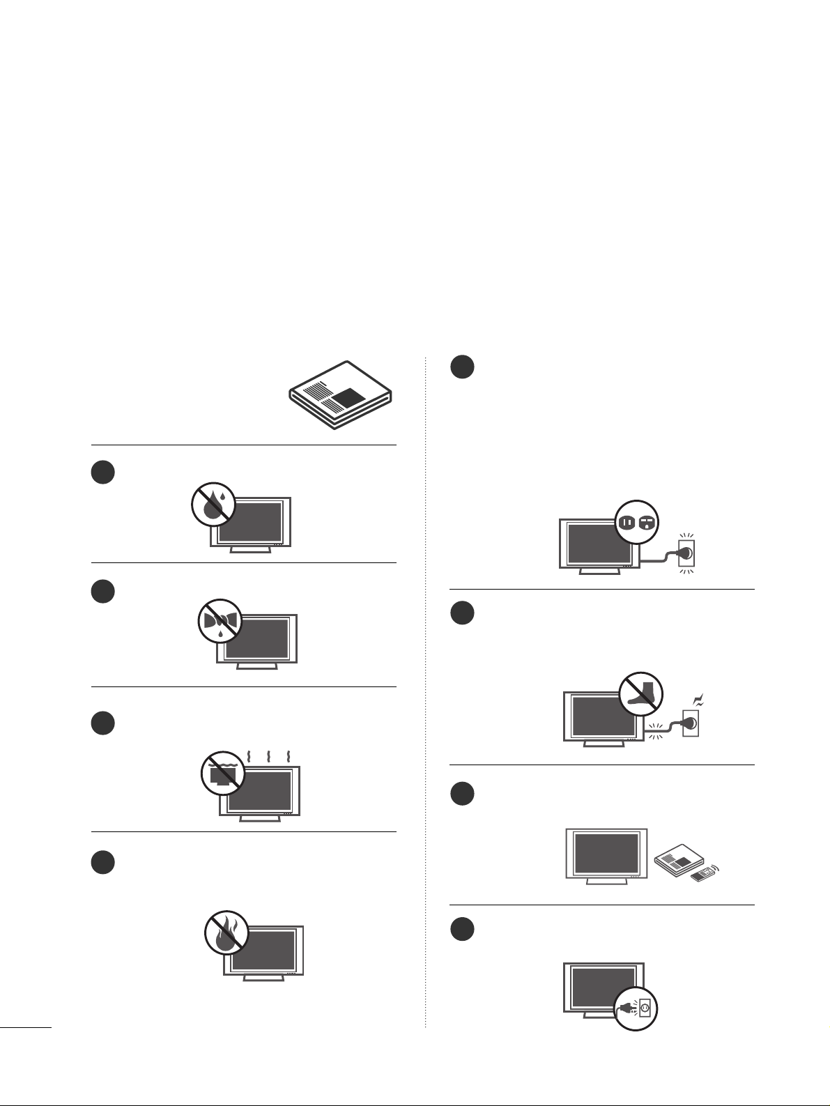
Read these instructions.
Keep these instructions.
Heed all warnings.
Follow all instructions.
Do not use this apparatus near water.
Clean only with dry cloth.
Do not block any ventilation openings. Install in
accordance with the manufacturer’s instructions.
Do not install near any heat sources such as
radiators, heat registers, stoves, or other apparatus
(including amplifiers)that produce heat.
Do not defeat the safety purpose of the polarized
or grounding-type plug. A polarized plug has
two blades with one wider than the other. A
grounding type plug has two blades and a third
grounding prong, The wide blade or the third
prong are provided for your safety. If the provided
plug does not fit into your outlet, consult an
electrician for replacement of the obsolete outlet.
Protect the power cord from being walked on
or pinched particularly at plugs, convenience
receptacles, and the point where they exit from
the apparatus.
Only use attachments/accessories specified by
the manufacturer.
Unplug this apparatus when unused for long
periods of time.
1
2
3
4
5
6
7
8
3
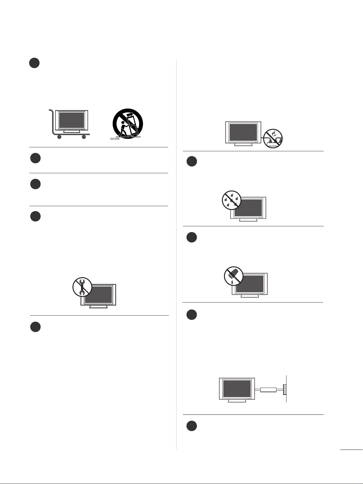
Use only with the cart, stand, tripod, bracket,
or table specified by the manufacturer, or sold
with the apparatus. When a cart is used, use
caution when moving the cart/apparatus
combination to avoid injury from tip-over.
Never touch this apparatus or antenna during
a thunder or lighting storm.
Do not allow a impact shock or any objects to
fall into the product, and do not drop onto the
screen with something.
Refer all servicing to qualified service personnel.
Servicing is required when the apparatus has
been damaged in any way, such as power-supply
cord or plug is damaged, liquid has been
spilled or objects have fallen into the apparatus,
the apparatus has exposed to rain or moisture,
does not operate normally, or has been
dropped.
CAUTION concerning the Power Cord :
Most appliances recommend they be placed
upon a dedicated circuit; that is, a single outlet
circuit which powers only that appliance and
has no additional outlets or branch circuits.
Check the specification page of this owner's
manual to be certain.
Do not overload wall outlets. Overloaded wall
outlets, loose or damaged wall outlets, extension
cords, frayed power cords, or damaged or
cracked wire insulation are dangerous. Any of
these conditions could result in electric shock
or fire. Periodically examine the cord of your
appliance, and if its appearance indicates damage or deterioration, unplug it, discontinue use
of the appliance, and have the cord replaced
with an exact replacement part by an authorized
servicer. Protect the power cord from physical
or mechanical abuse, such as being twisted,
kinked, pinched, closed in a door, or walked
upon. Pay particular attention to plugs, wall
outlets, and the point where the cord exits the
appliance.
Outdoor use marking :
WARNING - To reduce the risk of fire or elec-
tric shock, do not expose this appliance to rain
or moisture.
Wet Location Marking : Apparatus shall not be
exposed to dripping or splashing and no
objects filled with liquids, such as vases, shall
be placed on or over apparatus.
GGRROOUU NNDD IINNGG
Ensure that you connect the earth ground wire
to prevent possible electric shock. If grounding
methods are not possible, have a qualified
electrician install a separate circuit breaker.
Do not try to ground the unit by connecting it
to telephone wires, lightening rods, or gas pipes.
DDIISSCC OONNNNEECCTT IINNGG DDEEVVIICCEE FFRR OOMM MMAA IINNSS
Mains plug is the disconnecting device. The
plug must remain readily operable.
9
12
10
11
13
14
15
16
17
Power
Supply
Short-circuit
Breaker

4
CONTENTS
WARNING / CAUTION
. . . . . . . . . . . . . . . . . . . . . . . . . . . . 1
SAFETY INSTRUCTIONS
. . . . . . . . . . . . . . . . . . . . . . . . . . 2
INTRODUCTION
Feature of this TV
. . . . . . . . . . . . . . . . . . . . . . . . . . . . . . . . . . . . . . . . . . . . . 6
PREPARATION
Accessories
. . . . . . . . . . . . . . . . . . . . . . . . . . . . . . . . . . . . . . . . . . . . . . . . . . . . . .
7
Front Panel Information . . . . . . . . . . . . . . . . . . . . . . . . . . . . . . . . . . . . . 8
Back Panel Information
. . . . . . . . . . . . . . . . . . . . . . . . . . . . . . . . . . . . . . 9
Stand Installation . . . . . . . . . . . . . . . . . . . . . . . . . . . . . . . . . . . . . . . . . . . . 10
Back Cover for Wire Arrangement
. . . . . . . . . . . . . . . . . . . . .
10
Use Power Cord Holder
. . . . . . . . . . . . . . . . . . . . . . . . . . . . . . . . . . . . 11
Desktop Pedestal Installation
. . . . . . . . . . . . . . . . . . . . . . . . . . . . 11
Production Cover
. . . . . . . . . . . . . . . . . . . . . . . . . . . . . . . . . . . . . . . . . . . . . 11
Antenna or Cable Connection
. . . . . . . . . . . . . . . . . . . . . . . . . . 12
EXTERNAL EQUIPMENT SETUP
HD Receiver Setup
. . . . . . . . . . . . . . . . . . . . . . . . . . . . . . . . . . . . . . . . . 13
DVD Setup
. . . . . . . . . . . . . . . . . . . . . . . . . . . . . . . . . . . . . . . . . . . . . . . . . . . . . .
16
VCR Setup
. . . . . . . . . . . . . . . . . . . . . . . . . . . . . . . . . . . . . . . . . . . . . . . . . . . . . 18
Headphone Setup
. . . . . . . . . . . . . . . . . . . . . . . . . . . . . . . . . . . . . . . . . . . 20
PC Setup . . . . . . . . . . . . . . . . . . . . . . . . . . . . . . . . . . . . . . . . . . . . . . . . . . . . . . . .
21
WATCHING TV / CHANNEL CONTROL
Remote Control Functions
. . . . . . . . . . . . . . . . . . . . . . . . . . . . . . . 24
Turning On TV
. . . . . . . . . . . . . . . . . . . . . . . . . . . . . . . . . . . . . . . . . . . . . . . . 26
Channel Selection
. . . . . . . . . . . . . . . . . . . . . . . . . . . . . . . . . . . . . . . . . . . 26
Volume Adjustment
. . . . . . . . . . . . . . . . . . . . . . . . . . . . . . . . . . . . . . . . .
26
On-Screen Menus Selection
. . . . . . . . . . . . . . . . . . . . . . . . . . . . .
27
Channel Search
- Auto Scan (Auto Tuning)
. . . . . . . . . . . . . . . . . . . . . . . . . . .
28
- Add / Delete Channel (Manual Tuning) . . . . . . 29
- Channel Editing
. . . . . . . . . . . . . . . . . . . . . . . . . . . . . . . . . . . . . . . . 30
Key Lock
. . . . . . . . . . . . . . . . . . . . . . . . . . . . . . . . . . . . . . . . . . . . . . . . . . . . . . . . .
31
PICTURE CONTROL
Picture Size (Aspect Ratio) Control . . . . . . . . . . . . . . . . . . 32
Preset Picture Settings
- Picture Mode - Preset
. . . . . . . . . . . . . . . . . . . . . . . . . . . . . . . 34
- Color Tone - Preset
. . . . . . . . . . . . . . . . . . . . . . . . . . . . . . . . . . .
35
Manual Picture Adjustment
- Picture Mode - User Mode
. . . . . . . . . . . . . . . . . . . . . . . . 36
- Color Tone - User Mode
. . . . . . . . . . . . . . . . . . . . . . . . . . .
37
XD (Picture Improvement Technology)
. . . . . . . . . . . . .
38
Advanced - Black (Darkness) Level
. . . . . . . . . . . . . . . . . . . 39
Image Sticking Minimization (ISM) Method
. . . . . . 40
Low-Power Picture Mode
. . . . . . . . . . . . . . . . . . . . . . . . . . . . . . . . . . 41
Picture Reset
. . . . . . . . . . . . . . . . . . . . . . . . . . . . . . . . . . . . . . . . . . . . . . . . . .42
SOUND & LANGUAGE CONTROL
Preset Sound Setting (Sound Mode)
. . . . . . . . . . . . . . . . 43
Sound Setting Adjustment - User Mode
. . . . . . . . . . .44
Balance
. . . . . . . . . . . . . . . . . . . . . . . . . . . . . . . . . . . . . . . . . . . . . . . . . . . . . . . . . . 45
Stereo/SAP Broadcasts Setup
. . . . . . . . . . . . . . . . . . . . . . . . . . 46
Audio Language
. . . . . . . . . . . . . . . . . . . . . . . . . . . . . . . . . . . . . . . . . . . . . . 47
On-Screen Menus Language Selection
. . . . . . . . . . . . .
48
Caption Mode
. . . . . . . . . . . . . . . . . . . . . . . . . . . . . . . . . . . . . . . . . . . . . . . . 49
- Analog Broadcasting System Captions
. . . . . . . 50
- Digital Broadcasting System Captions
. . . . . . . .
51
- Caption Option
. . . . . . . . . . . . . . . . . . . . . . . . . . . . . . . . . . . . . . . .
52

5
TIME SETTING
Clock Setting
- Auto Clock Setup
. . . . . . . . . . . . . . . . . . . . . . . . . . . . . . . . . . . . 53
- Manual Clock Setup . . . . . . . . . . . . . . . . . . . . . . . . . . . . . . . . .
54
Auto On/Off Time Setting
. . . . . . . . . . . . . . . . . . . . . . . . . . . . . . 55
Sleep Time Setting
. . . . . . . . . . . . . . . . . . . . . . . . . . . . . . . . . . . . . . . . . .
56
Auto Shut-off Setting
. . . . . . . . . . . . . . . . . . . . . . . . . . . . . . . . . . . . . . . 57
PARENTAL CONTROL / RATINGS
Set Password & Lock System
. . . . . . . . . . . . . . . . . . . . . . . . . . .
58
Movie & TV Rating
. . . . . . . . . . . . . . . . . . . . . . . . . . . . . . . . . . . . . . . . . 60
APPENDIX
Troubleshooting
. . . . . . . . . . . . . . . . . . . . . . . . . . . . . . . . . . . . . . . . . . . . . . 63
Maintenance
. . . . . . . . . . . . . . . . . . . . . . . . . . . . . . . . . . . . . . . . . . . . . . . . . . .
65
Product Specifications
. . . . . . . . . . . . . . . . . . . . . . . . . . . . . . . . . . . . . 66
6
FEATURE OF THIS TV
INTRODUCTION
LG's own special digital image generator, consisting
of a full digital image processor, six different main
picture quality factors.
High-definition television. High-resolution digital
television broadcast and playback system composed
of roughly a million or more pixels, 16:9 aspect-ratio
screens, and AC3 digital audio. A subset of digital
television, HDTV formats include 1080i and 720p
resolutions.
Manufactured under license from Dolby Laboratories.
“
Dolby
“and the double-D symbol are trademarks of
Dolby Laboratories.
HDMITM, the HDMI logo and High-Definition
Multimedia Interface are trademarks or registered
trademarks of HDMI Licensing."
PREPARATION
7
PREPARATION
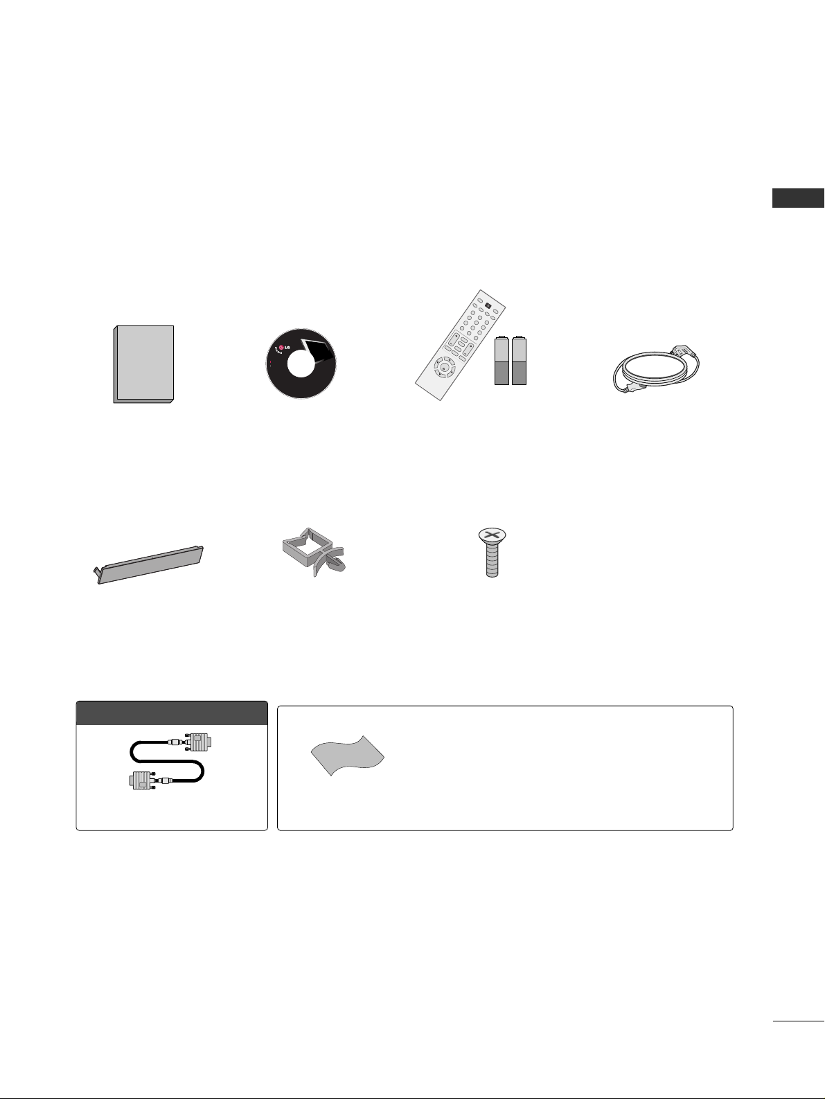
ACCESSORIES
Ensure that the following accessories are included with your product. If an accessory is missing, please contact
the dealer where you purchased the product.
User must use shielded signal interface cables (D-sub 15 pin cable) with ferrite cores to maintain standard
compliance for the product.
1.5V 1.5V
Owner’s Manual CD Manual
123
456
78
0-
9
V
O
L
C
H
B
A
C
K
M
U
T
E
A
D
J
U
S
T
E
X
IT
C
C
F
A
V
S
O
U
N
D
T
I
M
E
R
N
P
U
T
123
456
78
0-
9
V
O
L
C
H
E
N
T
E
R
P
O
W
E
R
B
A
C
K
M
U
T
E
M
E
N
U
A
D
J
U
S
T
E
X
I
T
C
C
S
A
P
F
A
V
P
I
C
T
U
R
E
S
O
U
N
D
T
I
M
E
R
T
V
I
N
P
U
T
Remote Control,
Batteries
Power Cord
LCD TV
Owner's Manual
http://www.lgusa.com
www.lg.ca
Copyright© 2007 LGE,
All Rights Reserved.
Protection Cover
(Refer to p.11)
OOppttiioonn EExxttrraass
Power Cord Holder
(Refer to p.11)
4-Bolts for stand assembly
(Refer to p.10)
* Slightly wipe stained spot on the exterior only with the polishing
cloth for the product exterior if there is stain or fingerprint on surface of the exterior.
* Do not wipe roughly when removing stain. Please be cautions of that
excessive pressure may cause scratch or discoloration.
Polishing Cloth
D-sub 15 pin Cable
PREPARATION
8
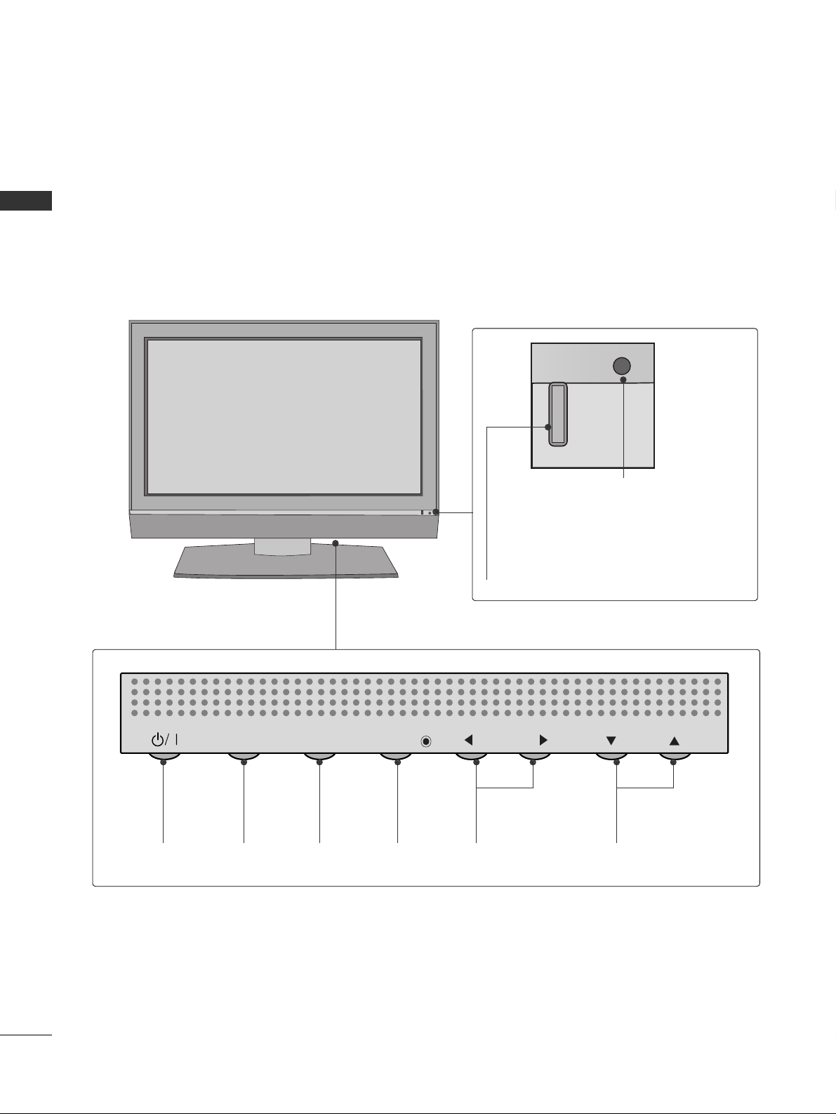
FRONT PANEL INFORMATION
PREPARATION
■
Here shown may be somewhat different from your TV.
■
NOTE: If your product has a protection tape attached, remove the tape.
And then wipe the product with a cloth (If a polishing cloth is included with your product, use it).
Power/Standby Indicator
Illuminates red in standby mode.
Illuminates green when the set is
switched on.
Remote Control Sensor
POWER
Button
INPUT
Button
MENU
Button
ENTER
Button
VOLUME
(
FF,GG
)Buttons
CHANNEL
(
EE,DD
)Buttons
INPUT
MENU
ENTER
VOL
CH
PREPARATION
9
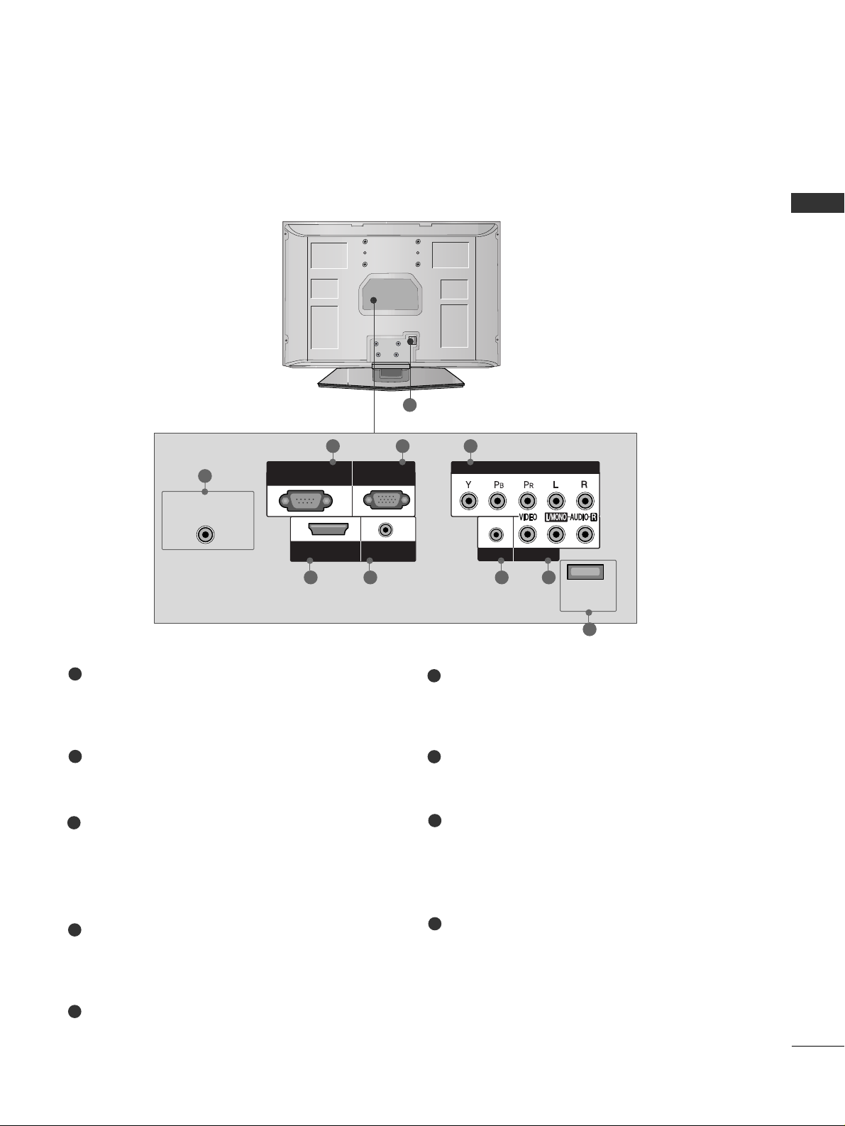
BACK PANEL INFORMATION
■
Here shown may be somewhat different from your TV.
9
ANTENNA/CABLE IN
Connect over-the air signals to this jack.
Connect cable signals to this jack.
RS-232C IN (CONTROL & SERVICE) PORT
For service.
RGB (PC) IN
Connect the output from a PC.
AUDIO (RGB/DVI) IN
Connect the audio from a PC or DTV.
COMPONENT IN
Connect a component video/audio device to
these jacks.
EXCLUSIVE SERVICE
AV IN (Audio/Video)
Connect audio/video output from an external
device to these jacks.
HEADPHONE INPUT
Plug the headphone into the headphone socket.
HDMI/DVI IN
Connect a HDMI signal to this jack.
Or DVI (Video) signal to this jack with a HDMI to
DVI cable.
Power Cord Socket
For operation with AC power.
Caution: Never attempt to operate the TV on DC
power.
1
2
3
4
5
6
7
ANTENNA/CABLE
IN
EXCLUSIVE
SERVICE
AV IN
HEADPHONE
COMPONENT IN
RGB IN
(PC)
RS-232C IN
(CONTROL & SERVICE)
AUDIO IN
(RGB/DVI)
HDMI/DVI
IN
8
9
1
2 3 4
38 67
5
PREPARATION
10
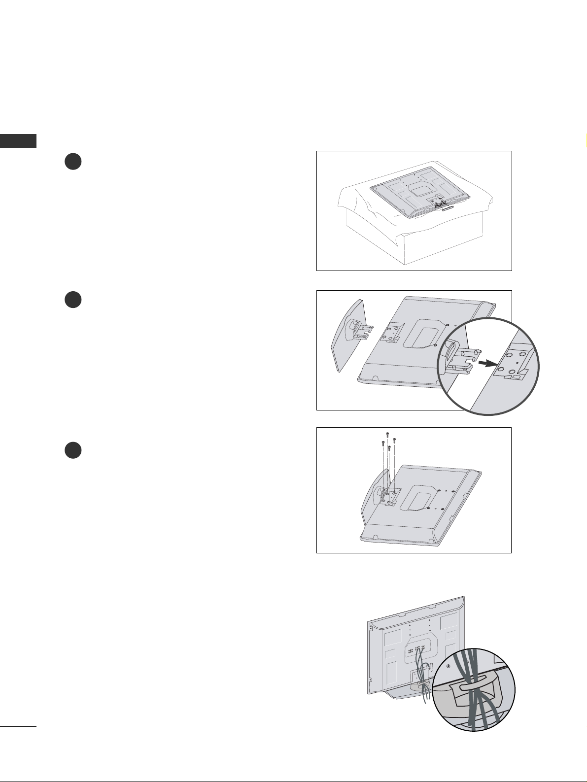
STAND INSTALLATION
PREPARATION
■
Here shown may be somewhat different from your TV.
Carefully place the product screen side down on
a cushioned surface that will protect product and
screen from damage.
Assemble the product stand with the product as
shown.
Install the 4 bolts securely, in the back of the
product in the holes provided.
1
2
3
BACK COVER FOR WIRE ARRANGEMENT
Arrange the cables as shown picture.
PREPARATION
11
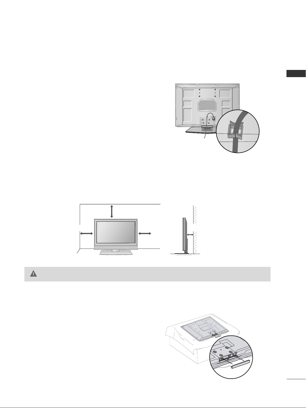
USE POWER CORD HOLDER
■
Here shown may be somewhat different from your TV.
After connecting the power cord to the AC input
terminal, remove the bolt at the hole on the back
cover and fix the power cord at the rear side of the
TV by using the bracket for fixing the power cord.
For proper ventilation, allow a clearance of 4 inches on all four sides from the wall.
GG
Ensure adequate ventilation by following the clearance recommendations.
CAUTION
DESKTOP PEDESTAL INSTALLATION
4 inches
4 inches
4 inches
4 inches
PROTECTION COVER
When installing the wall-mounted unit, use the protection
cover for desk-type stand installation.
PREPARATION
12
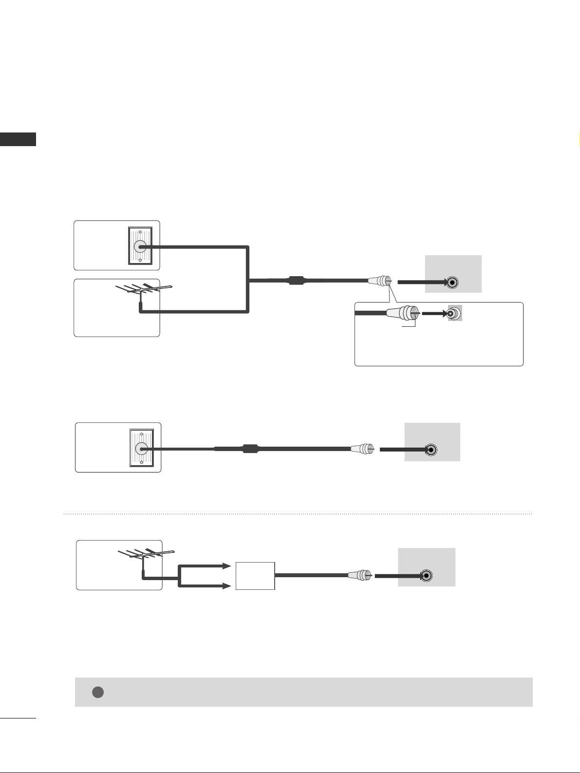
ANTENNA OR CABLE CONNECTION
PREPARATION
1. Antenna (Analog or Digital)
Wall Antenna Socket or Outdoor Antenna without a Cable Box
Connections.
For optimum picture quality, adjust antenna direction if needed.
2. Cable
Wa ll
Antenna
Socket
Outdoor
Antenna
(VHF, UHF)
Cable TV
Wall Jack
Multi-family Dwellings/Apartments
(Connect to wall antenna socket)
RF Coaxial Wire (75 ohm)
RF Coaxial Wire (75 ohm)
Single-family Dwellings /Houses
(Connect to wall jack for outdoor antenna)
Be careful not to bend the bronze wire
when connecting the antenna.
Copper Wire
ANTENNA/CABLE
IN
ANTENNA/CABLE
IN
ANTENNA/CABLE
IN
GG
The TV will let you know when the analog, cable, and digital channel scans are complete.
NOTE
!
■
To improve the picture quality in a poor signal area, please purchase a signal amplifier and install properly.
■
If the antenna needs to be split for two TV’s, install a 2-Way Signal Splitter.
■
If the antenna is not installed properly, contact your dealer for assistance.
Antenna
UHF
Signal
Amplifier
VHF
EXTERNAL EQUIPMENT SETUP
13
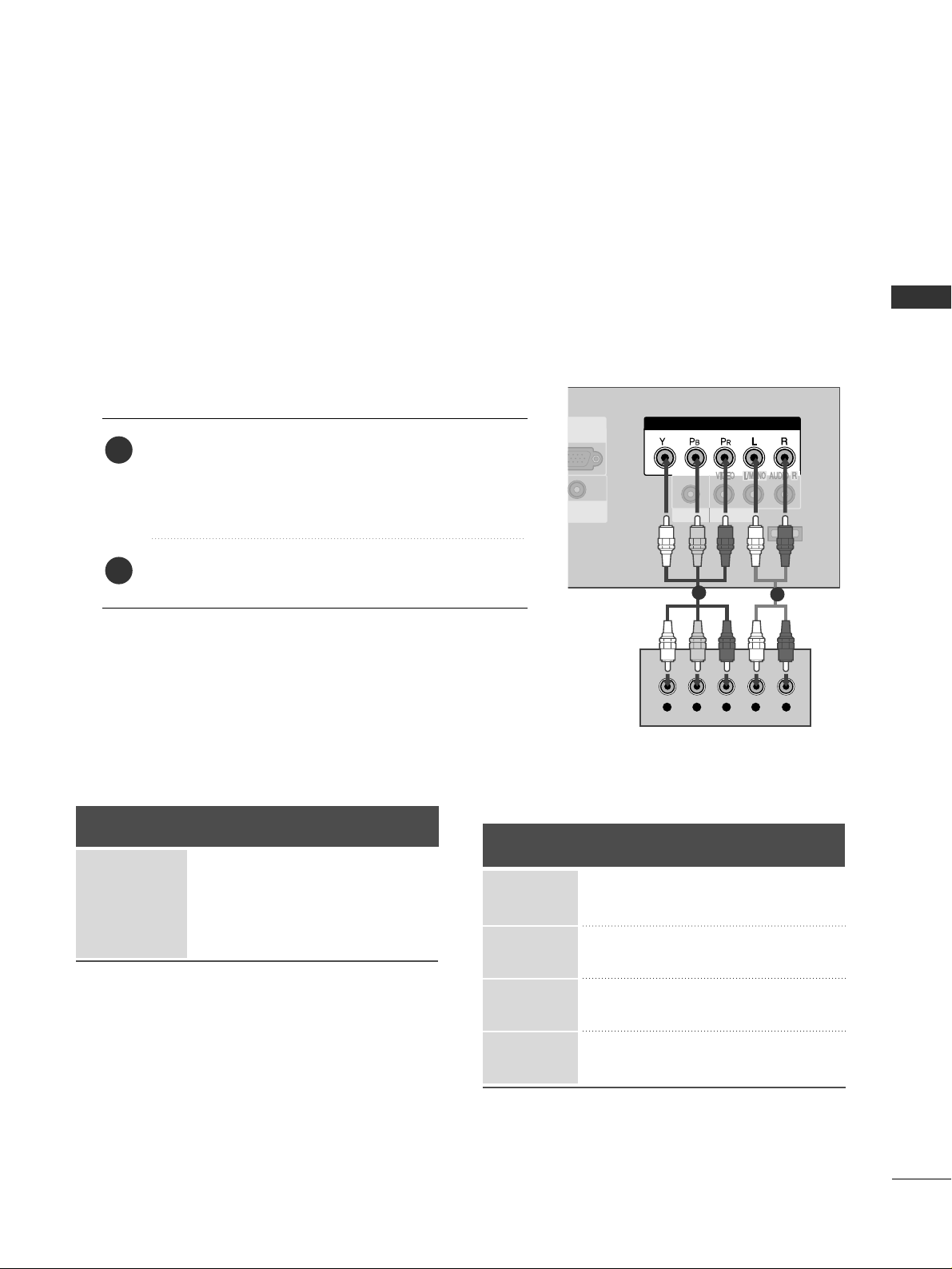
HD RECEIVER SETUP
EXTERNAL EQUIPMENT SETUP
This TV can receive Digital Over-the-air/Cable signals without an external digital set-top box. However, if you
do receive digital signals from a digital set-top box or other digital external device, refer to the figure as shown
below.
■
To prevent the equipment damage, never plug in any power cords until you have finished connecting all equipment.
EXCLUSIVE
SERVICE
AV IN
HEADPHONE
COMPONENT IN
Y L RPB PR
When connecting Component cable
1
2
1. How to connect
Connect the video outputs (Y, PB
, PR
)
of the digital set
top box to the
CC OOMMPPOO NN EENNTT IINN
((
YY ,, PP
BB
,, PP
RR
))
jacks
on the set. Match the jack colors
(Y = green, P
B
= blue, and PR = red).
Connect the audio output of the digital set-top box to
the
CC OOMMPPOO NN EENNTT IINN
((
LL ,, RR
))
jacks on the set.
2
1
2. How to use
■
Turn on the digital set-top box.
(
Refer to the owner’s manual for the digital set-top box. operation
)
■
Select
CC oo mmpp oo nneenntt
input source by using the
IINNPPUU TT
button on the remote control.
Signal
480i
480p
720p
10 8 0 i
Component
Yes
Yes
Yes
Yes
HDMI
No
Yes
Yes
Yes
Y, C
B/
PB
, CR/
P
R
Horizontal Vertical
Frequency(KHz)Frequency(Hz
)
15.73 59.94
15.73 60.00
31.47 59.94
31.50 60.00
44.96 59.94
45.00 60.00
33.72 59.94
33.75 60.00
Resolution
720x480i
720x480p
1280x720p
1920x1080i
EXTERNAL EQUIPMENT SETUP
14
EXTERNAL EQUIPMENT SETUP
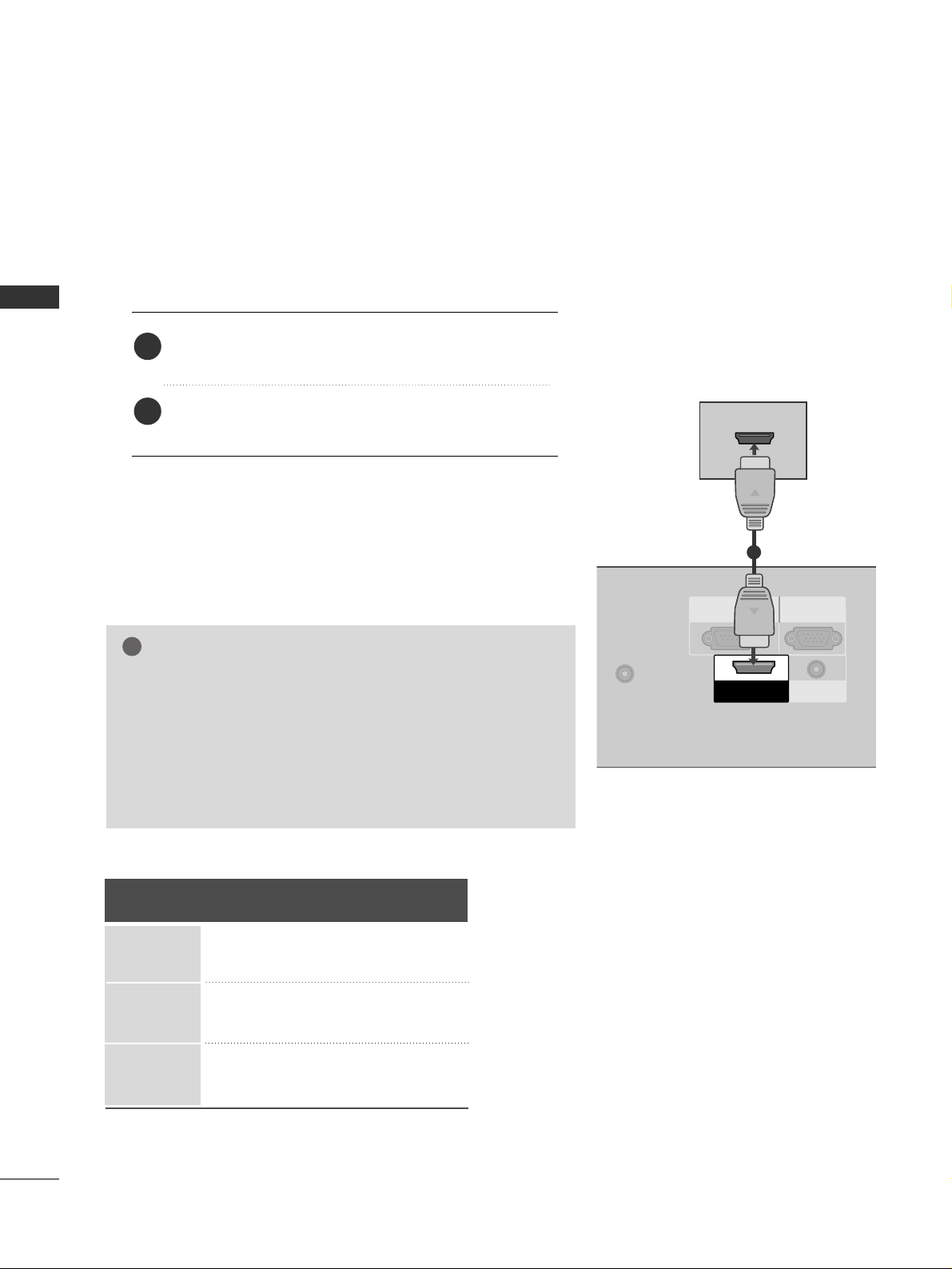
When connecting HDMI cable
Connect the digital set-top box to
HHDDMMII //DDVVII IINN
jack on the set.
No separated audio connection is necessary.
HDMI supports both audio and video.
1. How to connect
2. How to use
■
Turn on the digital set-top box.
(
Refer to the owner’s manual for the digital set-top box.
)
■
Select
HHDD MMII
input source by using the
IINN PPUUTT
button
on the remote control.
2
1
IN
RGB IN
(PC)
RS-232C IN
(CONTROL & SERVICE)
AUDIO IN
(RGB/DVI)
HDMI/DVI
IN
HDMI-DTV OUTPUT
1
GG
When connected, the TV will tell a connected device what
resolution it supports and the resolution it prefers. If the
device supports this Auto HDMI function, the player output
resolution will be automatically set to 720p.
GG
If the device does not support Auto HDMI, you need to set
the output resolution appropriately.
NOTE
!
HDMI/DVI-DTV mode
Horizontal Vertical
Frequency(KHz)Frequency(Hz
)
31.47 59.94
31.47 60.00
44.96 59.94
45.00 60.00
33.72 59.94
33.75 60.00
Resolution
720x480p
1280x720p
1920x1080i
EXTERNAL EQUIPMENT SETUP
15
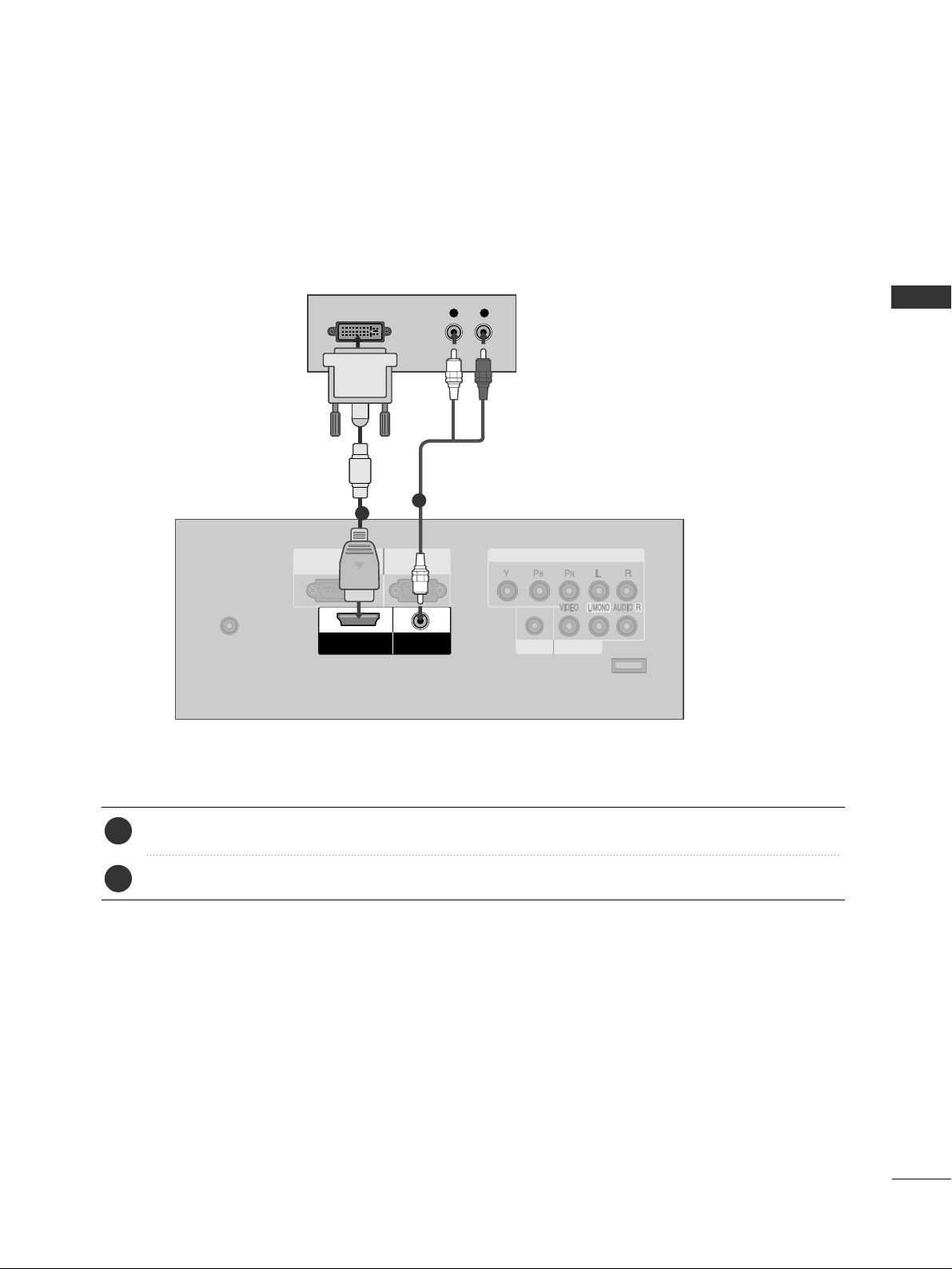
When connecting HDMI to DVI cable
ANTENNA/CABLE
IN
EXCLUSIVE
SERVICE
AV IN
HEADPHONE
COMPONENT IN
RGB IN
(PC)
RS-232C IN
(CONTROL & SERVICE)
AUDIO IN
(RGB/DVI)
HDMI/DVI
IN
L R
DVI-DTV OUTPUT
Connect the DVI output of the digital set-top box to the
HHDDMMII//DD VVII IINN
jack on the set.
Connect the audio output of the digital set-top box to the
AAUUDDIIOO IINN
((
RR GGBB //DD VVII
))
jack on the set.
1. How to connect
■
Turn on the digital set-top box. (Refer to the owner’s manual for the digital set-top box.
)
■
Select
HHDD MMII
input source by using the
IINNPPUU TT
button on the remote control.
2. How to use
2
1
1
2
EXTERNAL EQUIPMENT SETUP
16
DVD SETUP
EXTERNAL EQUIPMENT SETUP
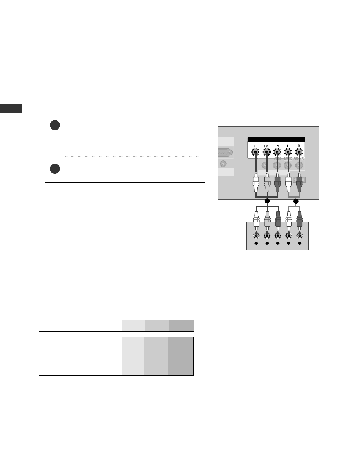
When connecting Component cable
EXCLUSIVE
SERVICE
AV IN
HEADPHONE
COMPONENT IN
GB IN
(PC)
Y L RPB PR
Component Input ports
To get better picture quality, connect a DVD player to the component input ports as shown below.
Component ports on the TV
YPBP
R
Video output ports
on DVD player
Y
Y
Y
Y
P
B
B-Y
Cb
Pb
P
R
R-Y
Cr
Pr
Connect the video outputs (Y, P
B, P
R
)
of the DVD to the
CC OOMMPPOO NN EENNTT IINN
((
YY ,, PP
BB
,, PP
RR
))
jacks on the set.
Match the jack colors
(
Y = green, P
B = blue, and P
R = red
)
.
Connect the audio outputs of the DVD to the
CC OOMMPPOO NN EENNTT IINN
((
LL ,, RR
))
jacks on the set.
1. How to connect
2. How to use
■
Turn on the DVD player, insert a DVD.
■
Select
CC oo mmpp oo nneenntt
input source by using the
IINNPPUU TT
button on the remote control.
■
Refer to the DVD player's manual for operating instructions.
2
1
1
2
EXTERNAL EQUIPMENT SETUP
17
ANTENNA/CABLE
IN
RGB IN
(PC)
RS-232C IN
(CONTROL & SERVICE)
AUDIO IN
(RGB/DVI)
HDMI/DVI
IN
HDMI-DVD OUTPUT
1
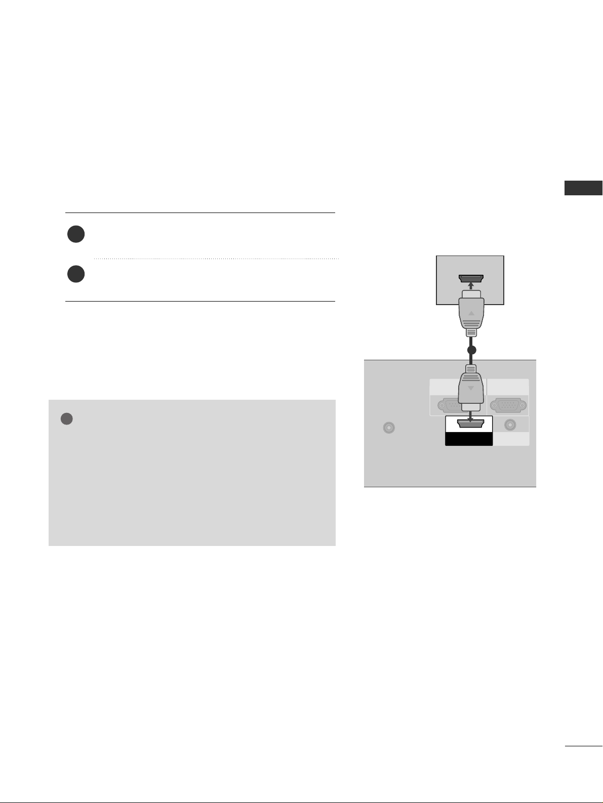
When connecting HDMI cable
Connect the HDMI output of the DVD to the
HHDDMMII//DD VVII IINN
jack on the set.
No separated audio connection is necessary.
HDMI supports both audio and video.
1. How to connect
2. How to use
■
Select
HHDD MMII
input source by using the
IINN PPUU TT
button
on the remote control.
■
Refer to the DVD player's manual for operating instructions.
2
1
GG
When connected, the TV will tell a connected device what
resolution it supports and the resolution it prefers. If the
device supports this Auto HDMI function, the player output resolution will be automatically set to 720p.
GG
If the device does not support Auto HDMI, you need to
set the output resolution appropriately.
To get the best picture quality, adjust the output resolution
of the DVD to 720p.
NOTE
!
EXTERNAL EQUIPMENT SETUP
18
VCR SETUP
EXTERNAL EQUIPMENT SETUP
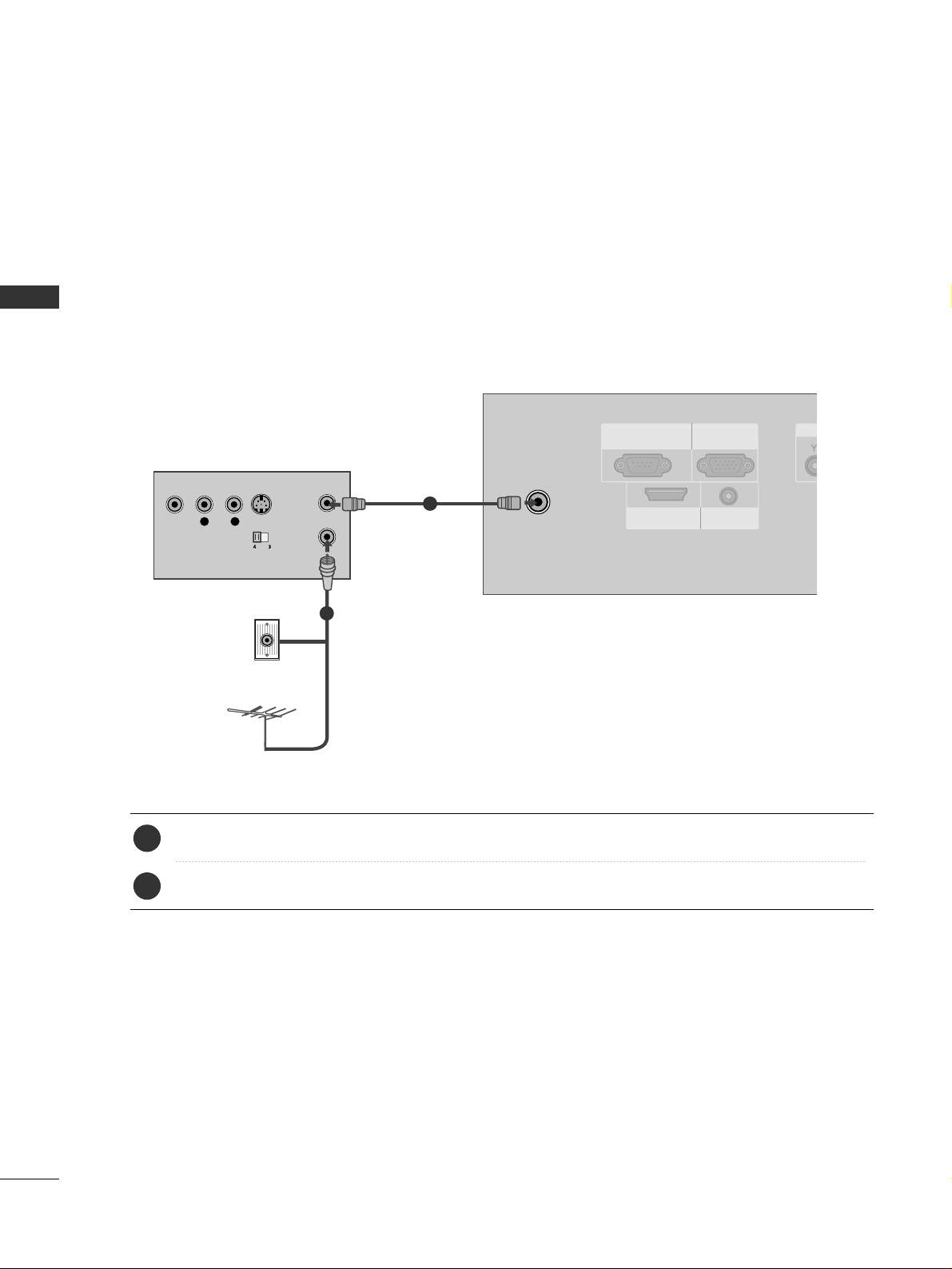
When connecting with an antenna
■
To avoid picture noise (interference), leave an adequate distance between the VCR and TV.
■
If the 4:3 picture format is used; the fixed images on the sides of the screen may remain visible on the
screen. This phenomenon is common to all manufactures and in consequence the manufactures warranty
does not cover the product bearing this phenomenon.
ANTENNA/CABLE
IN
RGB IN
(PC)
RS-232C IN
(CONTROL & SERVICE)
AUDIO IN
(RGB/DVI)
HDMI/DVI
IN
L R
S-VIDEOVIDEO
OUTPUT
SWITCH
ANT IN
ANT OUT
Wall Jack
Antenna
1
2
Connect the RF antenna out socket of the VCR to the
AANN TTEENNNNAA//CCAABBLL EE IINN
socket on the set.
Connect the antenna cable to the RF antenna in socket of the VCR.
1. How to connect
■
Set VCR output switch to 3 or 4 and then tune TV to the same channel number.
■
Insert a video tape into the VCR and press PLAY on the VCR. (Refer to the VCR owner’s manual.
)
2. How to use
2
1
EXTERNAL EQUIPMENT SETUP
19
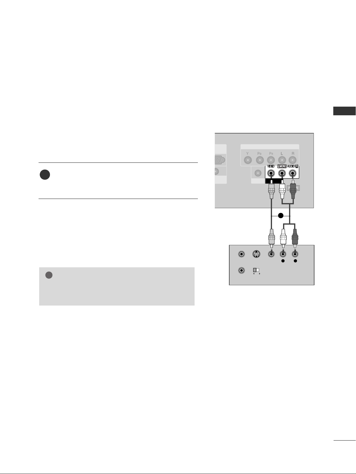
When connecting with a RCA cable
EXCLUSIVE
SERVICE
AV IN
HEADPHONE
COMPONENT IN
L R
S-VIDEO VIDEO
OUTPUT
SWITCH
ANT IN
ANT OUT
Connect the
AA UUDDII OO/VV IIDDEEOO
jacks between TV and
VCR. Match the jack colors (Video = yellow, Audio Left
= white, and Audio Right = red)
1. How to connect
2. How to use
■
Insert a video tape into the VCR and press PLAY on the
VCR. (Refer to the VCR owner’s manual.
)
■
Select
AA VV
input source by using the
IINNPPUU TT
button on the
remote control.
1
GG
If you have a mono VCR, connect the audio cable from
the VCR to the
AAUUDDII OO LL// MMOO NN OO
jack of the set.
NOTE
!
1

EXTERNAL EQUIPMENT SETUP
20
HEADPHONE SETUP
EXTERNAL EQUIPMENT SETUP
You can listen to the sound through the headphone.
Plug the headphone into the headphone socket.
To adjust the headphone volume, press the
VVOOLL
+ or
- button. If you press the
MMUUTTEE
button, the sound
from the headphone is switched off.
1. How to connect
2
1
EXCLUSIVE
SERVICE
AV IN
HEADPHONE
COMPONENT IN

EXTERNAL EQUIPMENT SETUP
21
PC SETUP
This TV provides Plug and Play capability, meaning that the PC adjusts automatically to the TV's settings.
When connecting D-sub 15pin cable
IN
RGB IN
(PC)
RS-232C IN
(CONTROL & SERVICE)
AUDIO IN
(RGB/DVI)
HDMI/DVI
IN
AUDIO
RGB OUTPUT
Connect the RGB output of the PC to the
RR GGBB IINN
((
PP CC
))
jack on the set.
Connect the PC audio output to the
AAUUDDIIOO IINN
((
RR GGBB //DD VVII
))
jack on the set.
1. How to connect
2. How to use
■
Turn on the PC and the TV.
■
Select
RR GGBB--PP CC
input source by using the
IINNPPUU TT
button
on the remote control.
2
1
1
2
When connecting HDMI to DVI cable
Connect the DVI output of the PC to the
HHDDMMII// DD VVII
II NN
jack on the set.
Connect the PC audio output to the
AAUUDDIIOO IINN
((
RR GGBB //DD VVII
))
jack on the set.
1. How to connect
2. How to use
■
Turn on the PC and the TV.
■
Select
HHDD MMII
input source by using the
IINNPPUU TT
button on
the remote control.
2
1
AUDIO
IN
HEAD
C
RGB IN
(PC)
RS-232C IN
(CONTROL & SERVICE)
AUDIO IN
(RGB/DVI)
HDMI/DVI
IN
DVI-PC OUTPUT AUDIO
1
2

EXTERNAL EQUIPMENT SETUP
22
EXTERNAL EQUIPMENT SETUP
GG
To get the the best picture quality, adjust the PC
graphics card to 852x480.
GG
Depending on the graphics card, DOS mode may
not work if a HDMI to DVI Cable is in use.
GG
If the video doesn’t fit the screen, try pressing the
ADJUST button to adjust the screen position of TV.
GG
Check the image on your TV. There may be noise
associated with the resolution, vertical pattern,
contrast or brightness in PC mode. If noise is
present, change the PC output to another resolution, change the refresh rate to another rate or
adjust the brightness and contrast on the PICTURE
menu until the picture is clear. If the refresh rate of
the PC graphic card can not be changed, change
the PC graphic card or consult the manufacturer of
the PC graphic card.
GG
Avoid keeping a fixed image on the screen for a
long period of time. The fixed image may become
permanently imprinted on the screen.
GG
The synchronization input form for Horizontal and
Vertical frequencies is separate.
NOTES
!
RGB-PC, HDMI/DVI-PC mode
Horizontal Vertical
Frequency(KHz)Frequency(Hz
)
31.47 70.09
31.468 70.08
31.469 59.94
29.83 59.659
32.0 60.491
37.879 60.31
48.363 60.00
Resolution
720x400
640x480
848x480
852x480
800x600
1024x768
640x350
Supported Display Specifications

EXTERNAL EQUIPMENT SETUP
23
Screen Setup for PC mode
Overview
When the RGB input of the set is connected to a PC output, select
the RGB-PC as the main input mode.
After connecting RGB-PC to PC output and checking the screen quality.
When you change the resolution, select the proper resolution in present input to see the best picture appearance.
Adjustment for screen Resolution, Position, Size,
and Phase
Press the
AADD JJUU SSTT
button and then use
DD
or EEbutton to
select
RR eessoolluu ttiioonn, PPoo ssiittiioonn, SSiizzee
, or
PPhhaa ss ee
.
Press the
EENNTTEERR
button and then use
DD EE FF GG
button to
make appropriate adjustments.
■
The
PPhhaassee
adjustment range is
00 ~++6633
.
■
The
SSiizzee
adjustment range is
--3300 ~++3300
.
Press the
EENNTTEERR
button.
Auto Configuration and Initializing
(Reset to original factory values)
Press the
AADD JJUU SSTT
button and then use
DD
or EEbutton to
select
AAuuttoo.. CC oo nnffiigg ..
or
RR ee ss eett
.
Press the
EENNTTEERR
button and then use
FF
or
GG
button to
select
YY ee ss
.
Press the
EENNTTEERR
button.
0-
VOL
CH
BACK
MUTE
ADJUST
CC
FAV
MENU EXIT
1
2
3
1
2
3
1 2 3
1 2 3
Auto Config.
Resolution
Position
Size
Phase
Reset
Select
Prev
OK
DD
EE
ADJUST
640 x 480
848 x 480
852 x 480
Initialize Settings
Yes
No
Select
Prev
OK
FF GG
ADJUST
Auto Config.
Resolution
Position
Size
Phase
Reset
Start Auto configuration
Yes
No
Select
Prev
OK
FF GG
ADJUST
Auto Config.
Resolution
Position
Size
Phase
Reset
AAuuttoo CCoonnffiigg..
This function is to adjust picture
position and minimizes image shaking automatically.
RReessoolluuttiioonn
This function allows you select
resolution of XGA/WXGA.
PPoossiittiioonn
This function is to adjust picture to
left/right and up/down as you prefer.
SSiizzee
This function is to minimize any
vertical bars or stripes visible on
the screen background. And the
horizontal screen size will also
change.
PPhhaassee
This function allows you to remove
any horizontal noise and clear or
sharpen the image of characters.
RReesseett
This function is to initialize the
adjusted value.

WATCHING TV / CHANNEL CONTROL
24
REMOTE CONTROL FUNCTIONS
WATCHING TV / CHANNEL CONTROL
When using the remote control, aim it at the remote control sensor on the TV.
123
456
780-9
VOL CH
ENTER
POWER
BACK
MUTE
MENU
ADJUST
EXIT
CC
SAP
FAV
PICTURE SOUND
TIMER
TV
INPUT
SAP
PICTURE
SOUND
TIMER
VOLUME UP
/DOWN
ADJUST
MUTE
CC
CHANNEL
UP/DOWN
MENU
BACK
EXIT
THUMBSTICK
(Up/Down/Left
Right/ENTER)
Analog mode: Selects MTS sound (Mono, Stereo, or a
SAP)
GG
pp..5500
DTV mode: Changes the audio language.
Selects the factory preset picture depend on the viewing
environment.
GG
pp..3344
Selects the factory preset sound for type of program.
GG
pp..4433
Select the amount of time before your TV turns off automatically.
GG
pp..5566
Increase/decrease the sound level.
Adjust the screen Auto config., Resolution, Position, Size
Phase and Reset.
GG
pp..2233
Switch the sound on or off.
GG
pp..2266
Select a closed caption.
GG
pp..4499
Select available channels.
Displays the main menu.
Tune to the last channel viewed.
Return to the previous menu.
Clear all on-screen displays and return to TV viewing from
any menu.
Navigate the on-screen menus and adjust the system settings to your preference.

WATCHING TV / CHANNEL CONTROL
25
■
Open the battery compartment cover on the back
side and install the batteries matching correct
polarity (+ with +, - with -).
■
Install two 1.5V AAA batteries. Don’t mix old or
used batteries with new ones.
■
Close cover.
■
Use a remote control up to 7 meters distance
and 30 degree (left/right) within the receiving
unit scope.
■
Dispose of used batteries in a recycle bin to
preserve environment.
123
456
780-9
POWER
SAP
FAV
PICTURE SOUND
TIMER
TV
INPUT
Installing Batteries
Remote control effective range
NUMBER button
Turns your TV on or off.
In AV, Component, RGB-PC, and HDMI input sources, screen returns to the last TV channel.
External input modes rotate in regular sequence: TV, AV, Component, RGB-PC, and HDMI.
(AV, Component, RGB-PC, and HDMI input sources are linked automatically, only if a device
is connected.)
Used to enter a program number for multiple program channels such as 2-1, 2-2, etc.
Scroll through the programmed Favorite channels.
GG
pp..3300
POWER
TV
INPUT
— (DASH)
FAV

WATCHING TV / CHANNEL CONTROL
26
TURNING ON TV
WATCHING TV / CHANNEL CONTROL
NOTE
!
GG
If you intend to be away on vacation, disconnect the power plug from the wall power outlet.
First, connect power cord correctly.
At this moment, the TV switches to standby mode.
■
In standby mode to turn TV on, press the ,
IINNPPUUTT,CCHH ((
DD
or
EE
))
button on the TV or press the
PPOOWWEERR, IINNPPUUTT, TTVV, CCHH ((
+ or -)),
NNuummbbeerr ((00~99))
button on the remote control.
Select the viewing source by using the
IINNPPUUTT
button on the remote con-
trol.
■
This TV is programmed to remember which power state it was last set
to, even if the power cord is out.
When finished using the TV, press the
PPOOWWEERR
button on the remote
control. The TV reverts to standby mode.
123
456
780-9
VOL
CH
POWER
BACK
MUTE
ADJUST
CC
SAP
FAV
MENU EXIT
PICTURE SOUND
TIMER
TV INPUT
1
2
3
123
456
780-9
VOL
CH
MUTE
ADJUST
CC
FAV
Press the
CCHH ((
+ or -))or
NNUUMMBBEERR
buttons to select a channel number.
1
VOLUME ADJUSTMENT
CHANNEL SELECTION
Press the
VVOOLL ((
+ or -))button to adjust the volume.
If you want to switch the sound off, press the
MMUUTTEE
button.
You can cancel the Mute function by pressing the
MMUUTTEE
or
VVOOLL ((
+ or -
))
button.
0-
VOL
CH
BACK
MUTE
ADJUST
CC
FAV
MENU EXIT
Adjust the volume to suit your personal preference.
1
2
3

WATCHING TV / CHANNEL CONTROL
27
ON-SCREEN MENUS SELECTION
Press the
MMEENNUU
button and then use
DD
or
EE
button to select the each menu.
Press the
GG
button and then use
DD EE FF GG
button to display the available menus.
Your TV's OSD (On Screen Display)may differ slightly from what is shown in this manual.
2
1
SETUP
PICTURE
TIME
AUDIO
Sound Mode : Standard
Balance : 0
Clock :
- - - -, - - - -, - - : - - - -
Off Time : Off
On Time : Off
Sleep Time : Off
Auto Sleep : Off
Language : English
Key Lock : Off
Caption : Off
ISM Method : Off
Low Power : Off
OPTION
Auto Tuning
Manual Tuning
Channel Edit
Picture Mode : User
Color Temperature : Cool
XD
Advanced
Aspect Ratio : 16:9
Picture Reset
LOCK
Lock System : Off
Set Password
Movie Rating
TV Rating-Children
TV Rating-General
Downloadable Rating
Lock System : Off
Set Password
TV Rating-English
TV Rating-French
Downloadable Rating
For USA
For Canada

WATCHING TV / CHANNEL CONTROL
28
CHANNEL SEARCH
WATCHING TV / CHANNEL CONTROL
Press the
MMEE NN UU
button and then use
DD
or
EE
button
to select the
SSEETTUU PP
menu.
Press the
GG
button and then use
DD
or
EE
button to
select
AAuuttoo TT uunn iinngg
.
Press the
EE NN TTEERR
button to begin the channel search.
Allow
AAuuttoo TT uunn iinngg
to complete the channel search
cycle for
AANN TTEENNNNAA
and
CC AABBLLEE
.
Automatically finds all channels available through antenna
or cable inputs, and stores them in memory on the channel
list.
Run Auto Tuning again after any Antenna/Cable connection
changes.
A password is required to gain access to Auto Tuning menu
if the Lock System is turned on.
2
3
1
ENTER
BACK
CC
MENU EXIT
Auto Scan (Auto Tuning)
1
2
3
Auto Tuning
Manual Tuning
Channel Edit
Auto Tuning
G
Manual Tuning
Channel Edit
Selection ( Gor )
leads you to the
Auto Tuning screen.
Auto Tuning
Manual Tuning
Channel Edit
Selection ( Gor )
leads you to the
Auto Tuning screen.
Processing Auto Tuning...
DTV Ch. 23
Found Channel(s) : 16
Press to stop the
current scan and start
TV channel scan.
BACK Prev
Next

WATCHING TV / CHANNEL CONTROL
29
A password is required to gain access to Manual Tuning
menu if the Lock System is turned on.
If selecting DTV or CADTV input signal, you can view the
on-screen signal strength monitor to see the quality of the
signal being received.
Press the
MMEE NN UU
button and then use
DD
or
EE
button
to select the
SSEETTUU PP
menu.
Press the
GG
button and then use
DD
or
EE
button to
select
MMaa nnuuaall TTuu nniinngg
.
Press the
GG
button and then use
DD
or
EE
button to
select
TT VV, DDTTVV, CC AATTVV
, and
CC AADD TTVV
.
Press the
GG
button and then use
DD
or
EE
button to
select channel you want to add or delete.
Press the
EENN TTEERR
button to add or delete the channel.
Press the
EE XX II TT
button to return to TV viewing or press
the
BB AACC KK
button to return to the previous menu.
ENTER
BACK
CC
MENU EXIT
2
1
4
3
6
5
Add/Delete Channel (Manual Tuning)
1
2
3 4 5
Auto Tuning
Manual Tuning
G
Channel Edit
Select channel type
and RF-Channel number
DTV 2
Auto Tuning
Manual Tuning
Channel Edit
Select channel type
and RF-Channel number
DTV
GG
12
Press to
delete the channel.
DTV 12-0
DD
EE
Bad Normal Good
Auto Tuning
Manual Tuning
Channel Edit

WATCHING TV / CHANNEL CONTROL
30
WATCHING TV / CHANNEL CONTROL
There are two different ways in order to add or delete
scanned channels. One is "Custom List" and the other is
"Favorite List" in the channel list. Both of them are available
after Auto Tuning on the SETUP menu.
A Custom List can be created by toggling each channel on
or off with ENTER button.
You can create your own Favorite List. Use the
FFAAVV
button
on the remote control when a channel is highlighted and
then add or delete the channel to/from your Favorite List.
Press the
MMEENNUU
button and then use
DD
or
EE
button
to select the
SSEETTUUPP
menu.
Press the
GG
button and then use
DD
or
EE
button to
select
CC hhaannnneell EEddiitt
.
Press the
GG
button and then use
DD
or
EE
button to
select
TT VV, DDTTVV, CC AATTVV
, and
CC AADD TTVV
.
Press the
GG
button and then use
DD
or
EE
button to
select channel and then use the
EENNTTEERR
button to add
or delete it.
Press
FFAAVV
button to add the channel to the Favorite List.
The surfing icon will appear in back of that channel
number.
Press the
EE XX II TT
button to return to TV viewing or press
the
BB AACC KK
button to return to the previous menu.
0-
VOL
CH
ENTER
BACK
MUTE
ADJUST
CC
FAV
MENU EXIT
2
1
3
4
5
Channel Editing
1
2
3 4
Auto Tuning
Manual Tuning
Channel Edit
Auto Tuning
Manual Tuning
Channel Edit
G
TV
2-0
4-0
6-0
9-0
11-0
13-0
14-0
Add/Delete
Favorite
FAV
Auto Tuning
Manual Tuning
Channel Edit
DD
EE
G
TV
Add/Delete
Favorite
FAV
2-0
4-0
6-0
9-0
11-0
13-0
14-0

WATCHING TV / CHANNEL CONTROL
31
KEY LOCK
ENTER
BACK
CC
MENU EXIT
The TV can be set up so that it can only be used with the
remote control.
This feature can be used to prevent unauthorized viewing
by locking out the front panel controls.
This TV is programmed to remember which option it was
last set to even if you turn the TV off.
Press the
MMEE NN UU
button and then use
DD
or
EE
button
to select the
OOPP TTII OONN
menu.
Press the
GG
button and then use
DD
or
EE
button to
select
KKee yy LLoo cckk
.
Press the
GG
button and then use
DD
or
EE
button to
select
OO nn
or
OOff ff
.
Press the
EE XX II TT
button to return to TV viewing or press
the
BB AACC KK
button to return to the previous menu.
2
3
4
1
1
2 3
Language : English
Key Lock : Off
Caption : Off
ISM Method : Off
Low Power : Off
Language
Key Lock
G
Caption
ISM Method
Low Power
Off
On

PICTURE CONTROL
32
PICTURE SIZE (ASPECT RATIO) CONTROL
PICTURE CONTROL
ENTER
BACK
CC
MENU EXIT
This feature allows an analog picture with a 4:3 aspect ratio is displayed on your TV.
When you receive an analog picture with a 4:3 aspect ratio on your 16:9 TV, you
need to specify how the picture is to be displayed.
■
RGB-PC input source use 4:3 or 16:9 aspect ratio.
NOTE
!
GG
If a fixed image is displayed on the screen for a long time, the image may
become imprinted on the screen and remain visible.
This phenomenon is common to all manufactures and in consequence the
manufactures warranty does not cover the product bearing this phenomenon.
Press the
MMEE NN UU
button and then use
DD
or
EE
button
to select the
PPII CCTTUU RREE
menu.
Press the
GG
button and then use
DD
or
EE
button to
select
AAssppeecctt RRaa ttiioo
.
Press the
GG
button and then use
DD
or
EE
button to
select the desired picture option
((
SSeett BB yy PPrroo ggrr aa mm
,
44::33,1166 ::99,HHoorr iizzoonn
, or
ZZoo oo mm
))
.
Press the
EE XX II TT
button to return to TV viewing or press
the
BB AACC KK
button to return to the previous menu.
2
3
4
1
1
32
Picture Mode
Color Temperature
XD
Advanced
Aspect Ratio
G
Picture Reset
Set By Program
4:3
16:9
Horizon
Zoom
Picture Mode : User
Color Temperature : Cool
XD
Advanced
Aspect Ratio : 16:9
Picture Reset

PICTURE CONTROL
33
Set by program
Selects the proper picture proportion to match
the source’s image.
4:3
Choose 4:3 when you want to view a picture
with an original 4:3 aspect ratio.
16:9
Adjust the picture horizontally, in a linear proportion to fill the entire screen.
Horizon
The screen size is, more enlarged at both sides,
to create a spectacular view.
Zoom
Choose Zoom when you want to view the picture without any alteration. However, the top
and bottom portions of the picture will be
cropped.
(4:3 4:3)
(16:9 16:9)

PICTURE CONTROL
34
PRESET PICTURE SETTINGS
PICTURE CONTROL
123
456
780-9
VOL
CH
POWER
MUTE
ADJUST
SAP
FAV
PICTURE SOUND
TIMER
TV INPUT
Picture Mode - Preset
Press the
PPII CCTTUU RREE
button repeatedly to select the picture
appearance setup option as below :
DDyynn aammii cc, SSttaa nnddaarr dd, MMii lldd
, and
UUsseerr
(your own settings).
Press the
EE XX II TT
button to save and return to TV viewing.
Picture Mode adjusts the TV for the best picture appearance.
Select the preset value in the Picture Mode menu based on the
program category.
DDyynnaammiicc,SSttaannddaarrdd,MMiilldd
Settings are preset for the optimum
picture quality at the factory and are not adjustable.
In the
UUssee rr
mode only, user can directly adjust the contrast,
brightness, color, sharpness, tint.
■
You can also use the
PPIICCTTUURREE
menu to adjust
PPiicc tt uurree MMoodd ee
.
2
1
Picture Mode : User
Color Temperature : Cool
XD
Advanced
Aspect Ratio : 16:9
Picture Reset
Picture Mode
G
Color Temperature
XD
Advanced
Aspect Ratio
Picture Reset
Dynamic
Standard
Mild
User

PICTURE CONTROL
35
VOL
CH
ENTER
BACK
MUTE
CC
MENU EXIT
Color Tone - Preset
Choose one of three automatic color adjustments. Set to
warm to enhance hotter colors such as red, or set to cool
to see less intense colors with more blue.
When selecting Picture Mode options (Dynamic, Standard
and Mild),
CC oo lloo rr TTeemmppeerr aa ttuurr ee
is automatically change.
When selecting Picture Mode options (User), you can
choose the
CC oo lloo rr TTeemmppeerr aa ttuurr ee
.
Press the
MMEE NN UU
button and then use
DD
or
EE
button
to select the
PPII CCTTUU RREE
menu.
Press the
GG
button and then use
DD
or
EE
button to
select
CCoo lloorr TT ee mmpp eerr aa ttuurree
.
Press the
GG
button and then use
DD
or
EE
button to
select either
CC oo oo ll,MMee dd iiuumm, WW aa rrmm
or
UUsseerr
.
Press the
EE XX II TT
button to return to TV viewing or press
the
BB AACC KK
button to return to the previous menu.
2
3
4
1
1
2 3
Picture Mode
Color Temperature
G
XD
Advanced
Aspect Ratio
Picture Reset
Cool
Medium
Warm
User
Picture Mode : User
Color Temperature : Cool
XD
Advanced
Aspect Ratio : 16:9
Picture Reset

PICTURE CONTROL
36
MANUAL PICTURE ADJUSTMENT
PICTURE CONTROL
VOL
CH
ENTER
BACK
MUTE
CC
MENU EXIT
Picture Mode - User Mode
Adjust the picture appearance to suit your preference and
viewing situations.
Press the
MMEE NN UU
button and then use
DD
or
EE
button
to select the
PPII CCTTUU RREE
menu.
Press the
GG
button and then use
DD
or
EE
button to
select
PPiicc tt uurree MMoodd ee
.
Press the
GG
button and then use
DD
or
EE
button to
select
UUsseerr
.
Press the
GG
button and then use
DD
or
EE
button to
select the desired picture option
((
CC oo nn ttrraa ss tt
,
BB rriigghhttnneessss,CCoo lloorr,SShhaarrppnneessss
, or
TT iinntt
))
.
Press the
GG
button and then useFFor GGbutton to
make appropriate adjustments.
Press the
EE XX II TT
button to return to TV viewing or press
the
BB AACC KK
button to return to the previous menu.
2
3
4
5
6
1
Contrast 85
EE
Picture Mode : User
Color Temperature : Cool
XD
Advanced
Aspect Ratio : 16:9
Picture Reset
EE
User
Contrast 85
G
Brightness 50
Color 50
Sharpness 50
Tint 0
R G
Press to confirm.
BACK
Picture Mode
Color Temperature
XD
Advanced
Aspect Ratio
Picture Reset
Dynamic
Standard
Mild
User
G
Selection ( Gor )
leads you to the
detailed setting screen.
2 3
1
4
5

PICTURE CONTROL
37
VOL
CH
ENTER
BACK
MUTE
CC
MENU EXIT
You can also adjust the detailed settings (Red, Green, Blue)
by selecting the
CCoolloorr TTee mmppee rraattuurree --UU ss eerr
menu.
This feature operate only if the picture mode set
UUsseerr
.
Color Tone - User Mode
Press the
MMEE NN UU
button and then use
DD
or
EE
button
to select the
PPII CCTTUU RREE
menu.
Press the
GG
button and then use
DD
or
EE
button to
select
CCoo lloorr TT ee mmpp eerr aa ttuurree
.
Press the
GG
button and then use
DD
or
EE
button to
select
UUsseerr
.
Press the
GG
button and then use
DD
or
EE
button to
select
RR ee dd, GGrr eeee nn
, or
BB lluuee
.
Press the
GG
button and then use
FF
or
GG
button to
make appropriate adjustments.
■
The adjustment range of
RR eedd, GGrr ee ee nn
, or
BB ll uu ee
is -
20
~ +20.
Press the
EE XX II TT
button to return to TV viewing or press
the
BB AACC KK
button to return to the previous menu.
2
3
4
5
6
1
2 3
1
4
5
Picture Mode
Color Temperature
XD
Advanced
Aspect Ratio
Picture Reset
Press to confirm.
BACK
Cool
Medium
Warm
User
G
User
Red 0
G
Green 0
Blue 0
Picture Mode : User
Color Temperature : Cool
XD
Advanced
Aspect Ratio : 16:9
Picture Reset
Red 0
FF
G
EE
Selection ( Gor )
leads you to the
detailed setting screen.
EE

PICTURE CONTROL
38
XD - PICTURE IMPROVEMENT TECHNOLOGY
PICTURE CONTROL
VOL
CH
ENTER
BACK
MUTE
CC
MENU EXIT
Press the
MMEE NN UU
button and then use
DD
or
EE
button
to select the
PPII CCTTUU RREE
menu.
Press the
GG
button and then use
DD
or
EE
button to
select
XX DD
.
Press the
GG
button and then use
DD
or
EE
button to
select
AAuutt oo orMMaa nnuuaa ll
.
Press the
EE XX II TT
button to return to TV viewing or press
the
BB AACC KK
button to return to the previous menu.
XD is LG’s unique picture improving technology to display
a real HD source through an advanced digital signal processing algorithm.
When selecting Picture Mode options (Dynamic, Standard,
and Mild), XD is automatically changed to Auto.
When selecting Picture Mode option (User), you can
choose the Auto / Manual.
When selecting the Manual, you can adjust the XD Contrast,
XD Color and XD Noise.
2
3
4
1
2 3
1
Picture Mode : User
Color Temperature : Cool
XD
Advanced
Aspect Ratio : 16:9
Picture Reset
Picture Mode
Color Temperature
XD
G
Advanced
Aspect Ratio
Picture Reset
Manual
XD Contrast On
XD Color On
XD Noise On
SSeelleecc ttiinngg tthhee MMaa nnuuaall
1. Press the
GG
button and then use
FF
or
GG
button to
select
XXDD CCoonnttrraasstt, XXDD CCoolloorr
or
XXDD NNooiissee
.
■
XX DD CCoonntt rraasstt::
Optimizing the contrast
automatically according to the brightness of
the reflection.
■
XX DD CCoolloorr ::
Adjusting the colors of the reflection automatically to reproduce as closely as
possible to the natural colors.
■
XX DD NNooii ss ee ::
Removing the noise up to the
point where it does not damage the original
picture.
2. Use the
DD
or
EE
button to select
OO nn
or
OOff ff
.

PICTURE CONTROL
39
ADVANCED - BLACK (DARKNESS) LEVEL
VOL
CH
ENTER
BACK
MUTE
CC
MENU EXIT
Press the
MMEE NN UU
button and then use
DD
or
EE
button
to select the
PPII CCTTUU RREE
menu.
Press the
GG
button and then use
DD
or
EE
button to
select
AAdd vvaa nncc eedd
.
Press the
GG
button and then use
DD
or
EE
button to
select
BB llaacckk llee vveell LLooww
or
HHiigghh
.
■
LL oo ww
The screen gets darker.
■
HHiigghh
The screen gets brighter.
Press the
EE XX II TT
button to return to TV viewing or press
the
BB AACC KK
button to return to the previous menu.
Adjusting the contrast and the brightness of the screen
using the black level of the screen.
This feature operates only in AV or HDMI mode.
2
3
4
1
2 3
1
Picture Mode
Color Temperature
XD
Advanced
G
Aspect Ratio
Picture Reset
Black Level Low
Picture Mode : User
Color Temperature : Cool
XD
Advanced
Aspect Ratio : 16:9
Picture Reset

PICTURE CONTROL
40
IMAGE STICKING MINIMIZATION (ISM) METHOD
PICTURE CONTROL
VOL
CH
ENTER
BACK
MUTE
CC
MENU EXIT
Press the
MMEE NN UU
button and then use
DD
or
EE
button
to select the
OOPP TTII OONN
menu.
Press the
GG
button and then use
DD
or
EE
button to
select
IISS MM MMeetthhoodd
.
Press the
GG
button and then use
DD
or
EE
button to
select either
NNoorr mmaa ll, OOrr bb iittee rr, IInn vveerr ss iioonn
, or
WW hhiittee
WW aasshh
.
■
NNoorr mmaa ll
If image sticking is never a problem, ISM is not necessary - set to Normal.
■
OOrr bb iittee rr
Orbiter may help prevent ghost images. However, it is
best not to allow any fixed image to remain on the
screen. To avoid a ghost image on the screen, the
image will move once per 2 minutes: Left Right
Upside Downside Right Left Downside
Upside.
■
IInn vveerr ss iioonn
Inversion will automatically invert the plasma display
panel color every 30 minutes.
■
WW hhiittee WWaa sshh
White Wash removes ghost images from the screen.
Use sparingly. Watch the TV normally for a while before
using this feature to see if the ghost image disappears on
its own.
Press
EE XX II TT
button to return to TV viewing or press
MMEE NN UU
button to return to the previous menu.
2
3
4
1
A frozen still picture from a PC/video game displayed on the
screen for prolonged periods will result in a ghost image.
Use our unique method to minimize any fixed image on the
screen.
GG
An excessive ghosted image may be impossible to
clear entirely with White Wash. To return to normal viewing, press the any button.
NOTE
!
Language : English
Key Lock : Off
Caption : Off
ISM Method : Off
Low Power : Off
Language
Input Label
SimpLink
Key Lock
Caption
ISM Method
G
Low Power
Set ID
Normal
Orbiter
Inversion
White Wash
2 3
1

PICTURE CONTROL
41
LOW - POWER PICTURE MODE
VOL
CH
ENTER
BACK
MUTE
CC
MENU EXIT
Press the
MMEE NN UU
button and then use
DD
or
EE
button
to select the
OOPP TTII OONN
menu.
Press the
GG
button and then use
DD
or
EE
button to
select
LLoo ww PPoo ww eerr
.
Press the
GG
button and then use
DD
or
EE
button to
select
OO nn
or
OOff ff
.
■
When you select
OO nn
, the screen darkens.
Press the
EE XX II TT
button to return to TV viewing or press
the
BB AACC KK
button to return to the previous menu.
Low power reduces the display power consumption.
2
3
4
1
1
Language : English
Key Lock : Off
Caption : Off
ISM Method : Off
Low Power : Off
Language
Key Lock
Caption
ISM Method
Low Power
G Off
On
2 3

PICTURE CONTROL
42
PICTURE RESET
PICTURE CONTROL
VOL
CH
ENTER
BACK
MUTE
CC
MENU EXIT
Press the
MMEE NN UU
button and then use
DD
or
EE
button
to select the
PPII CCTTUU RREE
menu.
Press the
GG
button and then use
DD
or
EE
button to
select
PPiiccttuurree RReesseett
.
Press the
GG
button to reset the Picture menu options
to original values.
Use to quickly reset all the Picture menu options to their
original factory preset values.
2
3
1
2 3
1
Picture Mode
Color Temperature
XD
Advanced
Aspect Ratio
Back Light
Picture Reset
G
Picture Mode : User
Color Temperature : Cool
XD
Advanced
Aspect Ratio : 16:9
Back Light : 100
Picture Reset
Selection ( Gor )
resets to the factory
setting (defaults).

123
456
780-9
VOL
CH
POWER
MUTE
ADJUST
SAP
FAV
PICTURE SOUND
TIMER
TV INPUT
SOUND & LANGUAGE CONTROL
43
PRESET SOUND SETTINGS (SOUND MODE)
SOUND & LANGUAGE CONTROL
Sound Mode lets you enjoy the best sound without any special
adjustment because the TV sets the appropriate sound options
based on the program content.
Standard, Music, Movie, and Sports are preset for good sound
quality at the factory and are not adjustable.
Press the
SSOO UUNNDD
button repeatedly to select the appropri-
ate sound setup as below :
SSttaa nnddaarr dd, MMuussiicc, MMoo vviiee, SSpp oo rrttss
, and
UUsseerr
(
your own
settings
).
Press the
EE XX II TT
button to save and return to TV viewing.
■
You can also adjust
SSoouunndd MMoo dd ee
in the
AAUUDDIIOO
menu.
2
1
Sound Mode
G
Balance
Standard
Music
Movie
Sports
User
Sound Mode : Standard
Balance : 0

SOUND & LANGUAGE CONTROL
44
SOUND & LANGUAGE CONTROL
SOUND SETTING ADJUSTMENT - USER MODE
VOL
CH
ENTER
BACK
MUTE
CC
MENU EXIT
Press the
MMEE NN UU
button and then use
DD
or
EE
button
to select the
AAUUDD II OO
menu.
Press the
GG
button and then use
DD
or
EE
button to
select
SSoouunndd MMoo dd ee
.
Press the
GG
button and then use
DD
or
EE
button to
select
UUsseerr
.
Press the
GG
button and then use
DD
or
EE
button to
select the desired sound option (
TT rreebbllee
or
BB aassss
).
Press the
GG
button and then use
FF
or
GG
button to
make appropriate adjustments.
Press the
EE XX II TT
button to return to TV viewing or press
the
BB AACC KK
button to return to the previous menu.
Adjust the sound to suit your taste and room situations.
2
3
4
5
6
1
Sound Mode
Balance
Standard
Music
Movie
Sports
User
G
User
Treble 50
G
Bass 50
Press to confirm.
BACK
2 3
4
5
1
Sound Mode : Standard
Balance : 0
Treble 85
FF
G
EE
Selection (
G
or )
leads you to the
detailed setting screen.
EE

SOUND & LANGUAGE CONTROL
45
BALANCE
VOL
CH
ENTER
BACK
MUTE
CC
MENU EXIT
Press the
MMEE NN UU
button and then use
DD
or
EE
button
to select the
AAUUDD II OO
menu.
Press the
GG
button and then use
DD
or
EE
button to
select
BB aa llaa nncc ee
.
Press the
GG
button and then use
FF
or
GG
button to
make appropriate adjustments.
Press the
EE XX II TT
button to return to TV viewing or press
the
BB AACC KK
button to return to the previous menu.
Adjust the left/right sound of speaker to suit your taste and
room situations.
L R
Balance 0
2
3
4
1
1
2
3
Sound Mode
Balance 0
L R
Sound Mode : Standard
Balance : 0

SOUND & LANGUAGE CONTROL
46
STEREO/SAP BROADCASTS SETUP
SOUND & LANGUAGE CONTROL
123
456
780-9
VOL
CH
POWER
MUTE
ADJUST
SAP
FAV
PICTURE SOUND
TIMER
TV INPUT
This TV can receive MTS stereo programs and any SAP
(
Secondary Audio Program)that accompanies the stereo program
if the station transmits an additional sound signal as well as the
original one and when you select Stereo or SAP on the remote
control.
Mono sound is automatically received if the broadcast is only in
Mono; even though Stereo or SAP has been selected.
Select Mono if you want to listen to the mono sound in remote
areas during stereo/SAP broadcasting.
Stereo or SAP can be received in Analog channel.
Use the
SS AAPP
button to select your desired MTS mode in
analog signal. Each time you press the
SS AAPP
button,
MMoonn oo
,
SSttee rreeoo
, or
SS AAPP
appear in turn.
■
If other languages available on the digital signal, select
them with the
SS AAPP
button.
Press
EE XX II TT
button to save and return to TV viewing.
2
1

SOUND & LANGUAGE CONTROL
47
AUDIO LANGUAGE
VOL
CH
ENTER
BACK
MUTE
CC
MENU EXIT
Other languages may be available if a digital signal is
provided by the broadcasting station.
This feature operates only in DTV/CADTV mode.
Press the
MMEE NN UU
button and then use
DD
or
EE
button
to select the
OOPP TTII OONN
menu.
Press the
GG
button and then use
DD
or
EE
button to
select
LLaa nngguu aagg ee
.
Press the
GG
button and then use
FF
or
GG
button to
select
AAuudd iioo
.
Use
DD
or
EE
button to select
EE nnggll iisshh, SSpp aa nniisshh
, or
FFrr ee nncchh
.
Press the
EE XX II TT
button to return to TV viewing or press
the
BB AACC KK
button to return to the previous menu.
2
3
4
5
1
2 3
1
4
Language : English
Key Lock : Off
Caption : Off
ISM Method : Off
Low Power : Off
Language
G
Key Lock
Caption
ISM Method
Low Power
Menu English
Audio English

SOUND & LANGUAGE CONTROL
48
ON-SCREEN MENUS LANGUAGE SELECTION
SOUND & LANGUAGE CONTROL
2 3
4
VOL
CH
ENTER
BACK
MUTE
CC
MENU EXIT
The menus can be shown on the screen in the selected
language. First select your language.
Press the
MMEENN UU
button and then use
DD
or
EE
button
to select the
OOPP TTII OONN
menu.
Press the
GG
button and then use
DD
or EEbutton to
select
LLaa nngguu aagg ee..
Press the
GG
button and then use
FF
or GGbutton to
select
MMee nnuu..
Use
DD
or
EE
button to select your desired language.
From this point on, the on-screen menus will be shown
in the selected language.
Press the
EE XX II TT
button to return to TV viewing or press
the
BB AACC KK
button to return to the previous menu.
1
2
3
4
5
1
Language : English
Key Lock : Off
Caption : Off
ISM Method : Off
Low Power : Off
Language
G
Key Lock
Caption
ISM Method
Low Power
Menu English
Audio English

SOUND & LANGUAGE CONTROL
49
CAPTION MODE
VOL
CH
ENTER
BACK
MUTE
CC
MENU EXIT
Caption must be provided to help people with hearing loss
watch TV.
Language : English
Key Lock : Off
Caption : Off
ISM Method : Off
Low Power : Off
Language
Key Lock
Caption
G
ISM Method
Low Power
Mode On
Analog Text1
Digital Service3
Digital Option
Use the
CC CC
button to select Caption
OO nn
or
OOff ff
.
■
When selecting
OOff ff
,
Sub-menus for Analog, DTV, and
Digital Option become disabled.
Press the
EE XX II TT
button to save and return to TV viewing.
2
1
■
You can also adjust
CC aa pp ttiioonn
in the
OOPPTTIIOONN
menu.

SOUND & LANGUAGE CONTROL
50
SOUND & LANGUAGE CONTROL
VOL
CH
ENTER
BACK
MUTE
CC
MENU EXIT
Analog Broadcasting System Captions
Select a caption mode for displaying captioning information
if provided on a program. Analog caption displays information at any position on the screen and is usually the program's dialog.
Caption/Text, if provided by the broadcaster, would be
available for both digital and analog channels on the
Antenna/Cable.
This TV is programmed to memorize the caption/text mode
which was last set when you turn the power off.
This function is only available when
CCaa pp tt iioonn
Mode is set
OO nn
.
Press the
MMEENN UU
button and then use
DD
or
EE
button
to select the
OOPP TTII OONN
menu.
Press the
GG
button and then use
DD
or EEbutton to
select
CC aapptt iioonn..
Press the
GG
button and then use
FF
or GGbutton to
select
AAnnaa lloogg..
Use
DD
or
EE
button to select
CC CC 11~ 44, TT ee xxtt 11 ~ 44
■
CC AAPP TTII OONN
The term for the words that scroll across the bottom of
the TV screen; usually the audio portion of the program provided for the hearing impaired.
■
TT EEXX TT
The term for the words that appear in a large black
frame and almost cover the entire screen; usually
messages provided by the broadcaster.
Press the
EE XX II TT
button to return to TV viewing or press
the
BB AACC KK
button to return to the previous menu.
1
2
3
4
5
1
3 42
Language : English
Key Lock : Off
Caption : Off
ISM Method : Off
Low Power : Off
Language
Key Lock
Caption
G
ISM Method
Low Power
Mode On
Analog Text1
Digital Service3
Digital Option

SOUND & LANGUAGE CONTROL
51
VOL
CH
ENTER
BACK
MUTE
CC
MENU EXIT
Press the
MMEE NN UU
button and then use
DD
or
EE
button
to select the
OOPP TTII OONN
menu.
Press the
GG
button and then use
DD
or
EE
button to
select
CC aa pp ttiioonn
.
Press the
GG
button and then use
FF
or
GG
button to
select
DDiigg iittaa ll
.
Use
DD
or
EE
button to select
SSeerr vviicc ee11~SSeerr vviicc ee66
.
Press the
EE XX II TT
button to return to TV viewing or press
the
BB AACC KK
button to return to the previous menu.
Choose the language you want the DTV/CADTV Captions
to appear in.
Other Languages can be chosen for digital sources only if
they are included on the program.
This function in only available when Caption Mode is set
On.
2
3
4
5
1
Digital Broadcasting System Captions
1
3 42
Language : English
Key Lock : Off
Caption : Off
ISM Method : Off
Low Power : Off
Language
Key Lock
Caption
G
ISM Method
Low Power
Mode On
Analog Text1
Digital Service3
Digital Option

SOUND & LANGUAGE CONTROL
52
SOUND & LANGUAGE CONTROL
VOL
CH
ENTER
BACK
MUTE
CC
MENU EXIT
Caption Option
Customize the DTV/CADTV captions that appear on your
screen.
This function in only available when Caption Mode is set
On.
Press the
MMEE NN UU
button and then use
DD
or
EE
button
to select the
OOPP TTII OONN
menu.
Press the
GG
button and then use
DD
or
EE
button to
select
CC aa pp ttiioonn
.
Press the
GG
button and then use
FF
or
GG
button to
select
DDiiggiittaall OO pp ttiioonn
.
Press the
GG
button and then use
DD
or
EE
button to
select
CC uusstt oo mm
.
Use
FF
or
GG
button to customize the
SStt yy llee, FFoo nntt
, etc.,
to your preference.
A preview icon is provided at the bottom of the screen,
use it to see the caption language.
■
SSiizzee
: Set the word size.
■
FFoonntt
: Select a typeface for the text.
■
TTeexxtt CCoolloorr
: Choose a color for the text.
■
TTeexxtt OOppaacciittyy
: Specify the opacity for the text color.
■
BBgg ((BBaacckkggrroouunndd))CCoolloorr
: Select a background color.
■
BBgg ((BBaacckkggrroouunndd))OOppaacciittyy
: Select the opacity for
the background color.
■
EEddggee TTyyppee
: Select an edge type.
■
EEddggee CCoolloorr
: Select a color for the edges.
Press the
EE XX II TT
button to return to TV viewing or press
the
BB AACC KK
button to return to the previous menu.
2
3
4
5
6
1
1
2 3
4 5
Language : English
Key Lock : Off
Caption : Off
ISM Method : Off
Low Power : Off
Language
Key Lock
Caption
ISM Method
Low Power
Mode On
Analog Text1
Digital Service3
Digital Option
G
Selection ( Gor ) leads you
to the Caption Option Screen.
Language
Key Lock
Caption
ISM Method
Low Power
Mode On
Analog Text1
Digital Service3
Digital Option
G
Selection ( Gor ) leads you
to the Caption Option Screen.
Style Custom
Size A Standard
Font Font 1
Text Color White
Text Opacity
Solid
Bg Color Black
Bg Opacity Solid
Edge Type None
Edge Color Black
DD
EE

VOL
CH
ENTER
BACK
MUTE
CC
MENU EXIT
TIME SETTING
53
CLOCK SETTING
TIME SETTING
Auto Clock Setup
The time is set automatically from a digital channel signal.
The digital channel signal includes information for the
current time provided by the broadcasting station.
Set the clock manually if the current time is set incorrectly
by the auto clock function.
Press the
MMEE NN UU
button and then use
DD
or
EE
button
to select the
TT IIMMEE
menu.
Press the
GG
button and then use
DD
or
EE
button to
select
CC lloo cckk
.
Press the
GG
button and then use
DD
or
EE
button to
select
AA uuttoo
.
Press the
GG
button and then use
DD
or
EE
button to
select your viewing area time zone:
U.S.A :
EE aasstt ee rr nn, CC ee nn ttrr aall, MMoo uunn ttaaii nn, PP aa cc ii ff ii cc
,
AAllaa sskkaa
or
HHaa ww aaii ii
.
Canada :
EE aasstt ee rrnn, CC ee nn ttrr aa ll, MMoouu nntt aaiinn, PP aa cc ii ff ii cc
,
NNeeww FF.. llaa nndd
or
AAtt llaa nnttiicc
.
Press the
GG
button and then use
DD
or
EE
button to
select
AA uuttoo, OOff ff, OO nn
, depending on whether or not
your viewing area observes Daylight Saving time.
Press the
EE XX II TT
button to return to TV viewing or press
the
BB AACC KK
button to return to the previous menu.
2
3
4
5
6
1
1
32
54
Clock
Off Time
On Time
Sleep Time
Auto sleep
Time Zone Eastern
Auto
Daylight
Saving
Clock :
- - - -, - - - -, - - : - - - -
Off Time : Off
On Time : Off
Sleep Time : Off
Auto sleep : Off
Year - - - Date - - / - Time - - : - - - -
Auto
Clock
Off Time
On Time
Sleep Time
Auto sleep
Auto
Year - - - Date - - / - Time - - : - - - -
Auto
Time Zone Eastern
Daylight
Saving
DD
EE
G
DD
EE
G

TIME SETTING
54
TIME SETTING
VOL
CH
ENTER
BACK
MUTE
CC
MENU EXIT
Manual Clock Setup
Press the
MMEE NN UU
button and then use
DD
or
EE
button
to select the
TT IIMMEE
menu.
Press the
GG
button and then use
DD
or
EE
button to
select
CC lloo cckk
.
Press the
GG
button and then use
DD
or
EE
button to
select
MMaa nnuuaa ll
.
Press the
GG
button and then use
FF
or
GG
button to
select either the year, date, or time option. Once
selected, use the
DD
or
EE
button to set the year, date,
and time options.
Press the
EE XX II TT
button to return to TV viewing or press
the
BB AACC KK
button to return to the previous menu.
If the current time setting is wrong, reset the clock manually.
2
3
4
5
1
1
32
Clock
Off Time
On Time
Sleep Time
Auto sleep
Clock :
- - - -, - - - -, - - : - - - -
Off Time : Off
On Time : Off
Sleep Time : Off
Auto sleep : Off
Year - - - Date - - / - Time - - : - - - -
Manual
DD
EE
G

TIME SETTING
55
AUTO ON/OFF TIME SETTING
VOL
CH
ENTER
BACK
MUTE
CC
MENU EXIT
Press the
MMEE NN UU
button and then use
DD
or
EE
button
to select the
TT IIMMEE
menu.
Press the
GG
button and then use
DD
or
EE
button to
select
OOffff TTiimmee
or
OOnn TTiimm ee
.
Press the
GG
button and then use
DD
or
EE
button to
select
OO nn
.
■
To cancel the
OOnn// OOffff tt iimmee
function, select
OOff ff
.
Press the
GG
button and then use
DD
or
EE
button to set
the hour.
Press the
GG
button and then use
DD
or
EE
button to set
the minutes.
OOnnll yy OOnn TT iimmee
Press the
GG
button and then use
DD
or
EE
button to
select the channel at turn-on.
Press the
GG
button and then use
DD
or
EE
button to set
the sound level at turn-on.
Press the
EE XX II TT
button to return to TV viewing or press
the
BB AACC KK
button to return to the previous menu.
2
3
4
5
6
7
1
This function operates only if the current time has been set.
The
OOffff TT iimmee
function overrides the
OOnn TT iimm ee
function if
they are both set to the same time.
The TV must be in standby mode for the
OOnn TTii mmee
to work.
If you do not press any button within 2 hours after the TV
turns on with the
OOnn TTiimmee
function, the TV will automati-
cally revert to standby mode.
1
32 54 6
Clock
Off Time
On Time
G
Sleep Time
Auto sleep
Off
On
Time 6 : 30 AM
Ch. TV 2-0
Vol. 17
Clock :
- - - -, - - - -, - - : - - - -
Off Time : Off
On Time : Off
Sleep Time : Off
Auto sleep : Off

TIME SETTING
56
TIME SETTING
123
456
780-9
VOL
CH
POWER
MUTE
ADJUST
SAP
FAV
PICTURE SOUND
TIMER
TV INPUT
SLEEP TIME SETTING
Press the
TT II MMEERR
button repeatedly to select the number of
minutes. First the
OOff ff
option appears on the screen, followed
by the following sleep timer options : 10, 20, 30, 60, 90,
120, 180, and 240 minutes.
When the number of minutes you want is displayed on the
screen, press the
EE NN TTEERR
button. The timer begins to count
down from the number of minutes selected.
To check the remaining minutes before the TV turns off, press
the
TT II MMEERR
button once.
To cancel the Sleep Time, press the
TT II MMEERR
button repeat-
edly to select
OOff ff
.
The Sleep Time turns the TV off at the preset time.
Note that this setting is cleared when the TV is turned off.
■
You can also set up the
SSlleeeepp TT iimmee
in the
TT IIMMEE
menu.
2
3
4
1
Clock
Off Time
On Time
Sleep Time
G
Auto sleep
Off
10 min
20 min
30 min
60 min
90 min
120 min
180 min
240 min
Clock :
- - - -, - - - -, - - : - - - -
Off Time : Off
On Time : Off
Sleep Time : Off
Auto sleep : Off

TIME SETTING
57
AUTO SHUT-OFF SETTING
VOL
CH
ENTER
BACK
MUTE
CC
MENU EXIT
If set to on and there is no input signal, the TV turns off
automatically after 10 minutes.
Press the
MMEE NN UU
button and then use
DD
or
EE
button
to select the
TT IIMMEE
menu.
Press the
GG
button and then use
DD
or
EE
button to
select
AAuuttoo sslleeeepp
.
Press the
GG
button and then use
DD
or
EE
button to
select
OO nn
or
OOff ff
.
Press the
EE XX II TT
button to return to TV viewing or press
the
BB AACC KK
button to return to the previous menu.
2
3
4
1
1
32
Clock
Off Time
On Time
Sleep Time
Auto sleep
G
Off
On
TV will be automatically
turned off, in case of
No Signal for 10 minutes.
Clock : Oct 19, 2007, 03:44 AM
Off Time : Off
On Time : Off
Sleep Time : Off
Auto sleep : Off

PARENTAL CONTROL / RATING
58
PARENTAL CONTROL / RATINGS
Parental Control can be used to block specific ratings.
The Parental Control Function (V-Chip) is used to block program viewing based on the ratings
sent by the broadcasting station. The default setting is to allow all programs to be viewed.
Viewing can be blocked by choosing the type of the program and the categories. It is also possible to block all program viewing for a time period. To use this function, the following must be
done :
1. Set ratings and categories to be blocked.
2. Specify a password
3. Enable the lock
V-Chip rating and categories
Rating guidelines are provided by broadcasting stations. Most television programs and television
movies can be blocked by TV Rating and/or Individual Categories. Movies that have been shown
at the theaters or direct-to-video movies use the Movie Rating System (MPAA)only.
Ratings for Television programs including made-for-TV movies :
■
TV-G(General audience
)
■
TV-PG(Parental guidance suggested
)
■
TV-14(Parents strongly cautioned
)
■
TV-MA (Mature audience only
)
■
TV-Y(All children
)
■
TV-Y7(Children 7 years older
)
SET PASSWORD & LOCK SYSTEM
Set up blocking schemes to block specific ratings.
A password is required to gain access to this menu.
Press the
MMEE NN UU
button and then use the
DD
or
EE
but-
ton to select the
LL OOCC KK
menu. Then, press the
GG
button.
■
Enter the password as requested.
■
The TV is set up with the initial password “0-0-0-0”.
1
Setting up Your Password
Lock System : Off
Set Password
Movie Rating
TV Rating-Children
TV Rating-General
Downloadable Rating
Lock System : Off
Set Password
TV Rating-English
TV Rating-French
Downloadable Rating
For USA
For Canada

PARENTAL CONTROL / RATING
59
After inputting the password, use the
DD
or
EE
button to
choose
SSeett ppaasssswwoo rrdd
.
Press the
GG
button and then choose any 4 digits for
your new password.
As soon as the 4 digits are entered, re-enter the same
4 digits on the
CC oo nnffiirrmm
.
Then your changed password has been memorized.
Press the
EE XX II TT
button to return to TV viewing or press
the
BB AACC KK
button to return to the previous menu.
Change the password by inputting a new password twice.
2
3
1
NOTE
!
GG
If you ever forget your password, key in ‘7’, ‘7’, ‘7’, ‘7’
on the remote control.
After inputting the password, use the
DD
or
EE
button to
choose
LLoo cckk SS yysstteemm
.
Press the
GG
button and then use the
DD
or
EE
button to
select
OO nn
or
OOff ff
.
■
When you select
OO nn
, the Lock System is enable.
Press the
EE XX II TT
button to return to TV viewing or press
the
BB AACC KK
button to return to the previous menu.
Enables or disables the blocking scheme you set up previously.
2
3
1
Set Password
Lock System
Lock System
Set Password
G
Movie Rating
TV Rating-Children
TV Rating-General
Downloadable Rating
New
Confirm
****
****
1
2
Lock System
G
Set Password
Movie Rating
TV Rating-Children
TV Rating-General
Downloadable Rating
Off
On
1
2
Lock System : Off
Set Password
Movie Rating
TV Rating-Children
TV Rating-General
Downloadable Rating
Lock System : Off
Set Password
TV Rating-English
TV Rating-French
Downloadable Rating
For USA
For Canada
Lock System : Off
Set Password
Movie Rating
TV Rating-Children
TV Rating-General
Downloadable Rating
Lock System : Off
Set Password
TV Rating-English
TV Rating-French
Downloadable Rating
For USA
For Canada

PARENTAL CONTROL / RATING
60
PARENTAL CONTROL /RATINGS
MOVIE & TV RATING
Lock System
Set Password
Movie Rating
G
TV Rating-Children
TV Rating-General
Downloadable Rating
Blocking off : Permits all
programs
G
PG
PG-13
R
NC-17
X
Blocking Off
1
2
Lock System : Off
Set Password
Movie Rating
TV Rating-Children
TV Rating-General
Downloadable Rating
Movie Rating (MPAA)
-
for USA only
Downloadable Rating
Blocks movies according to the movie ratings limits specified, so children
cannot view certain movies. You can set the ratings limit by blocking out all
the movies with the ratings above a specified level. Keep in mind that the
movie ratings limit only applies to movies shown on TV, not TV programs,
such as soap operas.
After inputting the password, use the
DD
or
EE
button to
choose
MMoo vviiee RRaattiinngg
.
Press the
GG
button and then use the
DD
or
EE
button to
select GG,
PP GG, PPGG --1133, RR, NNCC --1177
or XX.
■
G (General audience)
■
PG (Parental guidance suggested)
■
PG-13 (Parents strongly cautioned)
■
R (Restricted)
■
NC-17 (No one 17 and under admitted)
■
X (Adult only)
■
Blocking Off (Permits all programs)
Press
EE XX II TT
button to return to TV viewing or press
BB AACCKK
button to return to the previous menu.
GG
If you set PG-13 : G and PG movies will be available,
PG-13, R, NC-17 and X will be blocked.
2
3
1
After inputting the password, use the
DD
or
EE
button to
choose
DDoowwnnllooaaddaa bb llee RR aa ttiinn gg
.
Press the
GG
button and then use the
DD
or
EE
button to
select
DDiimm00, DDiimm11, DDiimm22
, or
DDiimm33
.
Press the
GG
button and then use the
DD
or
EE
button to
select
DD11 LL11, DD11 LL22
, or
DD11 LL33
.
Press
EE XX II TT
button to return to TV viewing or press
BB AACCKK
button to return to the previous menu.
2
3
4
1
Lock System
Set Password
Movie Rating
TV Rating-Children
TV Rating-General
Downloadable Rating
G
Downloadable Rating
1
2
Humer
Sports
Cruelty
language
Sadness
GG
This function may become available in the future and
will be available only for digital channel signal.
GG
This function operates only when TV has received
Region5 Rating data.
NOTE
!
GG
Based on rating table, your TV's OSD (On
Screen Display)may differ slightly from what
is shown in this manual.
Lock System : Off
Set Password
Movie Rating
TV Rating-Children
TV Rating-General
Downloadable Rating
Lock System : Off
Set Password
TV Rating-English
TV Rating-French
Downloadable Rating
For USA For Canada

PARENTAL CONTROL / RATING
61
TV Rating Children
-
for USA only
After inputting the password, use the
DD
or
EE
button to
choose
TTVV RRaattiinngg--CChhii llddrree nn
.
Press the
GG
button and then use the
DD
or
EE
button to
select
AA ggee
, or
FFaannttaassyy VViioolleennccee
.
Press the
GG
button and then use the
DD
or
EE
button to
select block options.
■
Age(applies to TV-Y, TV-Y7)
■
Fantasy Violence(applies to TV-Y7)
Press the
EE XX II TT
button to return to TV viewing or press
the
BB AACC KK
button to return to the previous menu.
Prevents children from watching certain children's TV programs, according to the ratings limit set. The children rating
does not apply to other TV programs. Unless you block certain TV programs intended for mature audiences in the TV
Rating - sub menu, your children can view those programs.
TV Rating General
-
for USA only
After inputting the password, use the
DD
or
EE
button to
choose
TTVV RRaattiinngg--GG eenneerraa ll
.
Press the
GG
button and then use the
DD
or
EE
button to
select
AA ggee, DDiiaalloogguu ee, LLaa nngguu aagg ee, SS ee xx
or
VV iioolleenncc ee
.
Press the
GG
button and then use the
DD
or
EE
button to
select block options.
■
Age(applies to TV-G,TV-PG,TV-14,TV-MA)
■
Dialogue-sexual dialogue (applies to TV-PG,TV-14)
■
Language-adult language (applies to TV-PG,TV-14,TV-MA)
■
Sex-sexual situations (applies to TV-PG,TV-14,TV-MA)
■
Violence (applies to TV-PG,TV-14,TV-MA)
Press the
EE XX II TT
button to return to TV viewing or press
the
BB AACC KK
button to return to the previous menu.
Based on the ratings, blocks certain TV programs that you
and your family do not want to view.
Lock System
Set Password
Movie Rating
TV Rating-Children
G
TV Rating-General
Downloadable Rating
Age
Fantasy Violence
Lock System
Set Password
Movie Rating
TV Rating-Children
TV Rating-General
G
Downloadable Rating
Age
Dialogue
Language
Sex
Violence
2
3
1
2
3
1
1
2
1
2
Lock System : Off
Set Password
Movie Rating
TV Rating-Children
TV Rating-General
Downloadable Rating
Lock System : Off
Set Password
Movie Rating
TV Rating-Children
TV Rating-General
Downloadable Rating

PARENTAL CONTROL / RATING
62
TV Rating English
-
for CANADA only
PARENTAL CONTROL /RATINGS
After inputting the password, use the
DD
or
EE
button to
choose
TTVV RRaattiinngg--EEnngg lliiss hh
.
Press the
GG
button and then use the
DD
or
EE
button to
select EE, CC,
CC 88 ++, GG, PP GG, 1144 ++, 1188 ++
, or
BB lloocckkiinngg OOffff
.
■
E (Exempt)
■
C (Children)
■
C8+ (Children eight years and older)
■
G (General programming, suitable for all audiences)
■
PG (Parental Guidance )
■
14+ (Viewers 14 years and older)
■
18+ (Adult programming)
■
Blocking Off (Permits all programs)
Press
EE XX II TT
button to return to TV viewing or press
BB AACCKK
button to return to the previous menu.
Selecting canadian english language rating system.
TV Rating French
-
for CANADA only
After inputting the password, use the
DD
or
EE
button
to choose
TTVV RR aattiinngg--FF rreenn cchh
.
Press the
GG
button and then use the
DD
or
EE
button
to select EE, GG,
88aa nnss++, 1133aa nnss++, 1166aa nnss++, 1188aa nnss++
,
or
BB lloocckkiinngg ooffff
.
■
E(Exempt)
■
G(General)
■
8ans+ (General-Not convenient for little children)
■
13ans+ (Not convenient for children of 13 years
and younger)
■
16ans+ (Not convenient for children of 16 years
and younger)
■
18ans+ (This programs is only for adults)
■
Blocking off (Permits all programs)
Press
EE XX II TT
button to return to TV viewing or press
BB AACCKK
button to return to the previous menu.
Selecting canadian french language rating system.
Lock System
Set Password
TV Rating-English
G
TV Rating-French
Downloadable Rating
Lock System
Set Password
TV Rating-English
TV Rating-French
G
Downloadable Rating
2
3
1
2
3
1
Blocking off : permits all
programs
E
C
C8+
G
PG
14+
18+
Blocking Off
Blocking off : permits all
programs
E
G
8 ans+
13 ans+
16 ans+
18 ans+
Blocking Off
1
2
1
2
Lock System : Off
Set Password
TV Rating-English
TV Rating-French
Downloadable Rating
Lock System : Off
Set Password
TV Rating-English
TV Rating-French
Downloadable Rating

APPENDIX
63
TROUBLESHOOTING
APPENDIX
TThhee ooppeerraattiioonn ddooeess nnoott wwoorrkk nnoorrmmaallllyy..
TThhee vviiddeeoo ffuunnccttiioonn ddooeess nnoott wwoorrkk..
No picture &No sound
No or poor color
or poor picture
Poor reception on
some channels
Lines or streaks
in pictures
Horizontal/vertical bars
or picture shaking
Picture appears slowly
after switching on
The remote control
doesn’t work
Power is suddenly
turned off
■
Check to see if there is any object between the product and the remote control
causing obstruction. Ensure you are pointing the remote control directly at the TV.
■
Ensure that the batteries are installed with correct polarity (+ to +, - to -).
■
Ensure that the correct remote operating mode is set: TV, VCR etc.
■
Install new batteries.
■
Is the sleep timer set?
■
Check the power control settings. Power interrupted.
■
No broadcast on station tuned with Auto off activated.
■
Check whether the product is turned on.
■
Try another channel. The problem may be with the broadcast.
■
Is the power cord inserted into wall power outlet?
■
Check your antenna direction and/or location.
■
Test the wall power outlet, plug another product’s power cord into the outlet
where the product’s power cord was plugged in.
■
This is normal, the image is muted during the product startup process. Please
contact your service center, if the picture has not appeared after five minutes.
■
Adjust Color in menu option.
■
Keep a sufficient distance between the product and the VCR.
■
Try another channel. The problem may be with the broadcast.
■
Are the video cables installed properly?
■
Activate any function to restore the brightness of the picture.
■
Check for local interference such as an electrical appliance or power tool.
■
Station or cable product experiencing problems, tune to another station.
■
Station signal is weak, reorient antenna to receive weaker station.
■
Check for sources of possible interference.
■
Check antenna (Change the direction of the antenna).

APPENDIX
64
APPENDIX
TThheerree iiss aa pprroobblleemm iinn PPCC mmooddee.. ((OOnnllyy PPCC mmooddee aapppplliieedd))
■
Adjust resolution, horizontal frequency, or vertical frequency.
■
Check the input source.
■
Work the Auto configure or adjust clock, phase, or H/V position. (Option)
■
Check the signal cable.
■
Reinstall the PC video card.
The signal is out of range
Screen color is unstable
or single color
Vertical bar or stripe on
background &
Horizontal Noise &
Incorrect position
■
Press the VOL or VOLUME button.
■
Sound muted? Press MUTE button.
■
Try another channel. The problem may be with the broadcast.
■
Are the audio cables installed properly?
■
Adjust Balance in menu option.
■
A change in ambient humidity or temperature may result in an unusual noise
when the product is turned on or off and does not indicate a fault with the
product.
Picture OK & No sound
Unusual sound from
inside
the product
No output from one
of the speakers
TThhee aauuddiioo ffuunnccttiioonn ddooeess nnoott wwoorrkk..

APPENDIX
65
MAINTENANCE
Early malfunctions can be prevented. Careful and regular cleaning can extend the amount of time you can
enjoy your new TV.
Caution: Be sure to turn the power off and unplug the power cord before you begin any cleaning.
Cleaning the Screen
Here’s a great way to keep the dust off your screen for a while. Wet a soft cloth in a mixture of lukewarm
water and a little fabric softener or dish washing detergent. Wring the cloth until it’s almost dry, and then
use it to wipe the screen.
Make sure the excess water is off the screen, and then let it air-dry before you turn on your TV.
Cleaning the Cabinet
■
To remove dirt or dust, wipe the cabinet with a soft, dry, lint-free cloth.
■
Please be sure not to use a wet cloth.
Extended Absence
GG
If you expect to leave your TV dormant for a long time (such as a vacation), it’s a good idea to unplug
the power cord to protect against possible damage from lightning or power surges.
CAUTION
2
1

APPENDIX
66
PRODUCT SPECIFICATIONS
APPENDIX
■
The specifications shown above may be changed without prior notice for quality improvement.
32PC5DVC
(32PC5DVC-UG)
MODELS
32.3 x 23.8 x 10.1 inches
819.9 x 603.8 x 255.4 mm
32.3 x 21.8 x 3.1 inches
819.9 x 554.2 x 78.1 mm
36.8 pounds / 16.7 kg
34.8 pounds / 15.8 kg
AC100-240V ~ 50/60Hz
NTSC-M, ATSC, 64 & 256 QAM
VHF 2-13, UHF 14-69, CATV 1-135, DTV 2-69, CADTV 1-135
75 ohm
32 ~ 104°F (0 ~ 40°C)
Less than 80%
-4 ~ 140°F (-20 ~ 60°C)
Less than 85%
Dimensions
(Width x Height x Depth)
Weight
Power requirement
Television System
Program Coverage
External Antenna Impedance
Environment condition
Including stand
Excluding stand
including stand
excluding stand
Operating Temperature
Operating Humidity
Storage Temperature
Storage Humidity


 Loading...