

Page 1

PLASMA TV
SERVICE MANUAL
CAUTION
BEFORE SERVICING THE CHASSIS,
READ THE SAFETY PRECAUTIONS IN THIS MANUAL.
CHASSIS : PP78D
MODEL : 32PC5DVC 32PC5DVC-UG
CANADA : http//biz.lgservice.com
USA : http//www.lgservice.com
: http//biz.lgservice.com
Internal Use Only
Page 2
- 2 -
Copyright©2008 LG Electronics. Inc. All right reserved.
Only for training and service purposes
LGE Internal Use Only
SAFETY PRECAUTIONS
Many electrical and mechanical parts in this chassis have special safety-related characteristics. These parts are identified by in the
Schematic Diagram and Replacement Parts List.
It is essential that these special safety parts should be replaced with the same components as recommended in this manual to prevent
X-RADIATION, Shock, Fire, or other Hazards.
Do not modify the original design without permission of manufacturer.
General Guidance
An lsolation Transformer should always be used during the
servicing of a receiver whose chassis is not isolated from the AC
power line. Use a transformer of adequate power rating as this
protects the technician from accidents resulting in personal injury
from electrical shocks.
It will also protect the receiver and it's components from being
damaged by accidental shorts of the circuitary that may be
inadvertently introduced during the service operation.
If any fuse (or Fusible Resistor) in this monitor is blown, replace it
with the same specified type.
When replacing a high wattage resistor (Oxide Metal Film Resistor,
over 1W), keep the resistor 10mm away from PCB.
Keep wires away from high voltage or high temperature parts.
Leakage Current Cold Check(Antenna Cold Check)
With the instrument AC plug removed from AC source, connect an
electrical jumper across the two AC plug prongs. Place the AC
switch in the on positioin, connect one lead of ohm-meter to the AC
plug prongs tied together and touch other ohm-meter lead in turn to
each exposed metallic parts such as antenna terminals, phone
jacks, etc.
If the exposed metallic part has a return path to the chassis, the
measured resistance should be between 1MΩ and 5.2MΩ.
When the exposed metal has no return path to the chassis the
reading must be infinite.
An other abnormality exists that must be corrected before the
receiver is returned to the customer.
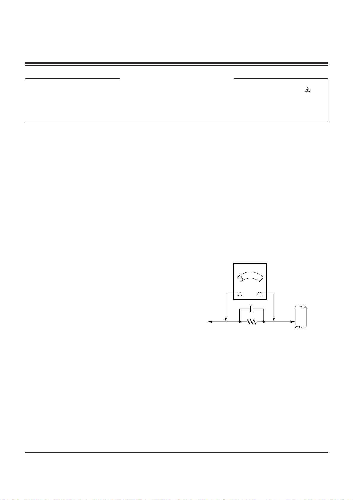
Leakage Current Hot Check (See below Figure)
Plug the AC cord directly into the AC outlet.
Do not use a line Isolation Transformer during this check.
Connect 1.5K/10watt resistor in parallel with a 0.15uF capacitor
between a known good earth ground (Water Pipe, Conduit, etc.)
and the exposed metallic parts.
Measure the AC voltage across the resistor using AC voltmeter
with 1000 ohms/volt or more sensitivity.
Reverse plug the AC cord into the AC outlet and repeat AC voltage
measurements for each esposed metallic part. Any voltage
measured must not exceed 0.75 volt RMS which is corresponds to
0.5mA.
In case any measurement is out of the limits sepcified, there is
possibility of shock hazard and the set must be checked and
repaired before it is returned to the customer.
Leakage Current Hot Check circuit
CANADA: LG Electronics Canada, Inc. 550 Matheson
Boulevard East Mississauga, Ontario L4Z 4G3
USA : LG Customer Interactive Center
P.O.Box 240007, 201 James Record Road Huntsville,
AL 35824
Digital TV Hotline 1-800-243-0000
1.5 Kohm/10W
To Instrument's
exposed
METALLIC PARTS
Good Earth Ground
such as WATER PIPE,
CONDUIT etc.
AC Volt-meter
IMPORTANT SAFETY NOTICE
0.15uF
Page 3

- 3 -
Copyright©2008 LG Electronics. Inc. All right reserved.
Only for training and service purposes
LGE Internal Use Only
SPECIFICATIONS.................................................................4
ADJUSTMENT INSTRUCTIONS ..........................................5
BLOCK DIAGRAM...............................................................10
EXPLODED VIEW...............................................................11
EXPLODED VIEW PARTS LIST.........................................12
SCHEMATIC DIAGRAM..........................................................
PRINTED CIRCUIT BOARDS.................................................
TABLE OF CONTENTS
Page 4
- 4 -
Copyright©2008 LG Electronics. Inc. All right reserved.
Only for training and service purposes
LGE Internal Use Only
The specifications shown above may be changed without prior notice for quality improvement.
32PC5DVC
(32PC5DVC-UG)
MODELS
32.3 x 23.8 x 10.1 inches
819.9 x 603.8 x 255.4 mm
32.3 x 21.8 x 3.1 inches
819.9 x 554.2 x 78.1 mm
36.8 pounds / 16.7 kg
34.8 pounds / 15.8 kg
AC100-240V ~ 50/60Hz
NTSC-M, ATSC, 64 & 256 QAM
VHF 2-13, UHF 14-69, CATV 1-135, DTV 2-69, CADTV 1-135
75 ohm
32 ~ 104°F (0 ~ 40°C)
Less than 80%
-4 ~ 140°F (-20 ~ 60°C)
Less than 85%
Dimensions
(Width x Height x Depth)
Weight
Power requirement
Television System
Program Coverage
External Antenna
Impedance
Environment condition
Including stand
Excluding stand
including stand
excluding stand
Operating
Temperature
Operating Humidity
Storage Temperature
Storage Humidity
SPECIFICATIONS
Page 5
- 5 -
Copyright©2008 LG Electronics. Inc. All right reserved.
Only for training and service purposes
LGE Internal Use Only
ADJUSTMENT INSTRUCTIONS
1. Application Range
This spec sheet is applied to all of the PP78D chassis .
2. Specification
(1) Because this is not a hot chassis, it is not necessary to use
an isolation transformer. However, the use of isolation
transformer will help to protect test instruments.
(2) Adjustment must be done in the correct sequence.
(3) The adjustment must be performed at 25±5°C temperature
and 65±10% relative humidity if there is no specified
designation.
(4) The input voltage of the receiver must be kept between
100~220V, 50/60Hz.
(5) Before adjustment, execute Heat-Run for 30 minutes at RF
no signal.
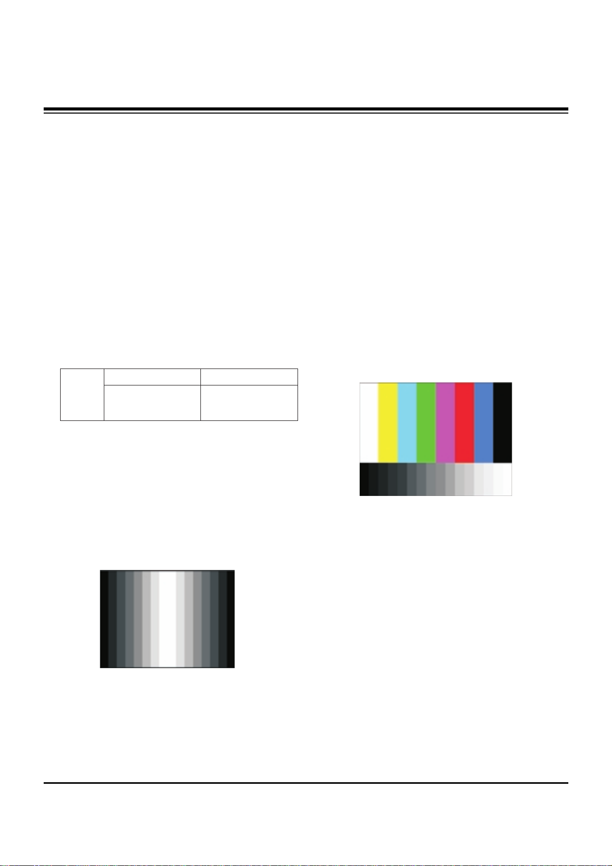
3. ADC Calibration
3-1. PC input ADC
(1) Auto RGB Gain/Offset Adjustment
1) Convert to PC in Input-source
2) Signal equipment displays
Output Voltage : 700 mVp-p
Impress Resolution XGA (800 x 600 @ 60Hz)
Model : 46 in Pattern Generator
Pattern : 29 in Pattern Generator (MSPG-925 SERISE)
[gray pattern that left & right is black and center is white
signal (Refer below picture)]
3) Adjust by commanding AUTO_COLOR_ADJUST(0xF1)
0x00 0x02 instruction.
(2) Confirmation
1) We confirm whether “0xB6(RGB)” address of EEPROM
“0xA2” is “0xAA” or not.
2) If “0xB6(RGB)” address of EEPROM “0xB2” isn’t “0xAA”,
we adjust once more
3) We can confirm the ADC values from
“0xB0~0xB5(RGB)” addresses in a page “0xA2”
[ Manual ADC process using Service Remocon. After enter
Service Mode by pushing “ADJ” key, execute “ADC Adjust”
by pushing “
G” key at “Adjust-RGB”.
3-2. COMPONENT input ADC
(1) Component Gain/Offset Adjustment
1) Convert to Component in Input-source
2) Signal equipment displays
Impress Resolution 720P
MODEL : 216 in Pattern Generator(720P Mode)
PATTERN : 08 in Pattern Generator(MSPG-925 SERISE)
3) Adjust by commanding AUTO_COLOR_ADJUST(0xF1)
0x00 0x02 instruction
(2) Confirmation
1) We confirm whether “0xC8(720P)” address of EEPROM
“0xA2” is “0xAA” or not.
2) If “0xC8(720P)” address of EEPROM “0xA2” isn’t
“0xAA”, we adjust once more
3) We can confirm the ADC values from “0xB9~
0xBE(480i)/0xC2~(1080i)” addresses in a page “0xA2”
MSPG-
925FA
Component
Model: 216
(720p@60Hz)
Model: 46
(800x600@60Hz)
RGB
Adjustment pattern (PC)
Adjustment pattern (COMPONENT)
Page 6

- 6 -
3-3. Function Check
(1) Check display and sound
1) Check Input and Signal items. (cf. work instructions)
1. TV
2. AV (CVBS/ S-Video)
3. COMPONENT (480i)
4. RGB (PC : 1024 x 768 @ 60hz)
5. HDMI
6. PC Audio In and H/P Out
* Display and Sound check is executed by Remote
controller.
4. EDID
[
Caution
(1) Use the proper signal cable for EDID Download
- Analog EDID : Pin3 exists
- Digital EDID : Pin3 exists
(2) Never connect HDMI & DVI-D & DVI-A Cable at the same
time.
(3) Use the proper cables below for EDID Writing
4-1. EDID Data
(1) 32PC5DV ANALOG(128 Bytes )
O BLOCK1 (128BYTE)
(2) 32PC5DV HDMI(256 Bytes)
O BLOCK1 (128BYTE)
O BLOCK2 (128BYTE)
(2) 32PC5DVC HDMI(256 Bytes)
O BLOCK1 (128BYTE)
O BLOCK2 (128BYTE)
Copyright©2008 LG Electronics. Inc. All right reserved.
Only for training and service purposes
LGE Internal Use Only
ADJUSTMENT INSTRUCTIONS
Caution: Each PCB assembly must be checked by check JIG set.
(Because power PCB Assembly damages to PDP Module,
especially be careful)
Item
Manufacturer ID
Version
Revision
Condition
GSM
Digital : 1
Digital : 3
Hex Data
1E6D
01
03
For RGB EDID For HDMI EDID
Page 7

- 7 -
ⓐ Product ID
ⓑ Serial No
=> Controlled on production line
ⓒ Month, Year
=> Controlled on production line:
ex) Monthly: ‘11’ -> ‘0B’
Year: ‘2006’ -> ‘10’
ⓓ Model Name/Monitor Name
ⓔ Checksum(7EH)
=> Changeable by total EDID data
4-2. Required Test Equipment
(1) Adjusting PC with S/W for writing EDID Data.(S/W : EDID
TESTER Ver.2.5)
(2) A Jig for EDID Download
(3) Cable : Serial(9Pin or USB) to D-sub 15Pin cable, D-sub
15Pin cable, DVI to HDMI cable.
4-3. Preparation for Adjustment
(1) As above (Fig. 1), Connect the Set, EDID Download Jig,,
PC & Cable
(2) Turn on the PC & EDID Download Jig. And Execute the
S/W : EDID TESTER Ver.2.5
(3) Set up the S/W option
Repeat Number : 5
Device Address : A0
PageByte : 8
(4) Power on the Set
4-4. Sequence of Adjustment
DDC data of Analog-RGB
(1) Init the data
(2) Load the EDID data.(Open File).
(3) Set the S/W as below.
Copyright©2008 LG Electronics. Inc. All right reserved.
Only for training and service purposes
LGE Internal Use Only
ADJUSTMENT INSTRUCTIONS
TV set
or
Main B/D
(Fig. 1) Connection Diagram of DDC Download
Open FileOpen File
[Analog – RGB :
PP78D_RGB.ANA ]
[Digital – HDMI :
PP78D_HDMI.DVI ]
Page 8

- 8 -
(4) Push the “Write Data & Verify” button. And confirm “Yes”.
(5) If the writing is finished, you will see the “ OK” message.
5. HDCP(High-Bandwidth Digital Contents Protection)
(1) Connect D-sub Signal Cable to D-Sub Jack
(2) Input HDCP key with HDCP-key- in-program
(3) HDCP Key value is stored on EEPROM(AT24C512) which
is 80~A1 addresses of 0xA0~0xA2 page
(4) AC off/ on and on HDCP button of MSPG925 and confirm
whether picture is displayed or not of using MSPG925
(5) HDCP Key value is different among the sets
6. Adjustment of White Balance
6-1. Purpose and Principle for Adjustment
of the Color Temperature
(1) Purpose: Adjust the color temperature to reduce the
deviation of the module color temperature.
(2) Principle: To adjust the white balance without the
saturation, Fix the one of R/G/B gain to 80 and decrease
the others.
6-2. Adjustment Mode
Two modes of Cool and Warm
(Medium data is automatically calibrated by the cool data)
6-3. Required Equipment
(1) Remote controller for adjustment
(2) Color Analyzer : CA100, CA-100+, CA-210 or same
product
- PLASMA TV(ch : 10)
(3) Auto W/B adjustment instrument(only for Auto adjustment)
6-4. Connecting Diagram of Equipment
for Measuring
(For Automatic Adjustment)
(1) Enter the adjustment mode of the white balance
1) Enter the white balance adjustment mode at the same
time heat-run mode when pushing the power on by
power only key
2) Maintain the white balance adjustment mode with same
condition of Heat-run -> Maintain after AC off/on in
status of Heat-run pattern display
(2) Release the white balance adjustment mode
1) Release the adjust mode after AC off/on or std-by off/on
in status of finishing the Hear-run mode
2) Release the Adjust mode when receiving the aging off
command(F3 00 00) from adjustment equipment
3) Need to transmit the aging off command to TV set after
finishing the adjustment
Copyright©2008 LG Electronics. Inc. All right reserved.
Only for training and service purposes
LGE Internal Use Only
ADJUSTMENT INSTRUCTIONS
Page 9
- 9 -
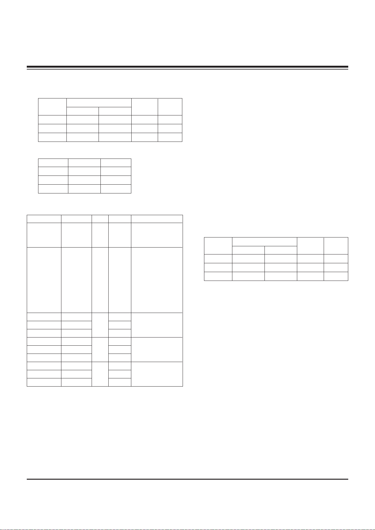
O
Standard color coordinate and temperature when using the
CA-100+ or CA210 equipment
O
Synchronization relation between PSM and CSM
(3) DDC adjustment Command set
[ R/G/B GAIN max value : 80
6-5. Adjustment of White Balance for
Manual Adjustment
(1) Adjustment mode: Two modes of Cool (Dynamic) and
Warm(Mild)
(Medium data is automatically calibrated by the cool data)
(2) Color analyzer(CA110) should be used in the calibrated ch
by CS-1000(PDP : CH10)
(3) Operate the zero-calibration of the CA-110 then stick
sensor to the module when adjusting.
(4) For manual adjustment, it is also possible by the following
sequence
1) Select white pattern of heat-run by pressing “POWER
ON” key on remote control for adjustment then operate
heat run longer than 15 minutes.
(If not executed this step, the condition for W/B will be
differ )
2) Changing to the av mode by remote control.(av mode)
3) Display the internal pattern of the Mstar IC by pushing
the ADJ.
4) Stick sensor to center of the screen and select each
items (Red/Green/Blue Gain and Offset) using
D/E
(CH
+/-) key on R/C.
5) Adjust R/ G/B Gain using
F/G (VOL +/-) key on R/C.
6) Adjust two modes of Cool(Dynamic) and Warm(Mild) as
below figure.
(Fix the one of R/G/B and change the others)
1. Push the one time the in-start key : Cool
2. Push the two more the in-start key : Warm
[ Refer to the below case to know what value is fixed.
[CASE]
First adjust the coordinate much away from the target
value (x, y).
1. x, y > target
Decrease the R, G.
2. x, y < target
1) First decrease the B gain,
2) Decrease the one of the others.
- In case of decreasing the x, decreasing the R : fix G
- In case of decreasing the y , decreasing the G : fix R
3. x > target , y < target
1) First decrease B, so make y a little more than the
target.
2) Adjust x value by decreasing the R
4. x < target , y > target
1) First decrease B, so make x a little more than the
target.
2) Adjust x value by decreasing the G
7) When adjustment is completed, Exit adjustment mode
using EXIT key on R/C
Copyright©2008 LG Electronics. Inc. All right reserved.
Only for training and service purposes
LGE Internal Use Only
ADJUSTMENT INSTRUCTIONS
Color Coordinate
XY
0.283±0.003
0.293±0.003
0.329±0.00
3
11,000K
9,300K
6,500K
0.000
0.000
0.003
0.276±0.003
0.285±0.003
0.313±0.00
3
Cool
Medium
Warm
Mode
Temp
3uv
CSM Remark
Cool
Normal
Warm
Dynamic
Standard
Mild
PSM
Adjustment
Aging On/Off
Input select
R GAIN
G GAIN
B GAIN
R GAIN
G GAIN
B GAIN
R GAIN
G GAIN
B GAIN
CMD(HEX)
F3
F4
16
18
1A
16
18
1A
16
18
1A
ADR
00
00
00
01
02
VALUE
255/00
00 - 255
00 - 255
00 - 255
00 - 255
00 - 255
00 - 255
00 - 255
00 - 255
00 - 255
Detail
OO : OFF
01 : ON
FF : WB Ready
0x10 : TV
0x20 : AV1
0x21 : AV2
0x23 : AV3
0x40 : Component1
0x50 : RGB DTV
0x60 : RGB PC
0x90 : HDMI1 DTV
GAIN adjustment
CSM COOL
GAIN adjustment
CSM NORMAL
GAIN adjustment
CSM WARM
Color Coordinate
XY
0.283±0.003
0.293±0.003
0.329±0.00
3
11,000K
9,300K
6,500K
0.000
0.000
0.003
0.276±0.003
0.285±0.003
0.313±0.00
3
Cool
Medium
Warm
Mode
Temp
3uv
Page 10

- 10 -
Copyright©2008 LG Electronics. Inc. All right reserved.
Only for training and service purposes
LGE Internal Use Only
BLOCK DIAGRAM
Page 11

- 11 -
LGE Internal Use Only
EXPLODED VIEW
A21
A2
300
570
560
120
301
302
303
304
305
200
240
580
400
520
590
201
202
203
900
* Option
250
204
Many electrical and mechanical parts in this chassis have special safety-related characteristics. These
parts are identified by in the Schematic Diagram and EXPLODED VIEW.
It is essential that these special safety parts should be replaced with the same components as
recommended in this manual to prevent X-RADIATION, Shock, Fire, or other Hazards.
Do not modify the original design without permission of manufacturer.
IMPORTANT SAFETY NOTICE
Page 12

Copyright©2008 LG Electronics. Inc. All right reserved.
Only for training and service purposes
LGE Internal Use Only
Page 13

Copyright©2008 LG Electronics. Inc. All right reserved.
Only for training and service purposes
LGE Internal Use Only
Page 14

Copyright©2008 LG Electronics. Inc. All right reserved.
Only for training and service purposes
LGE Internal Use Only
Page 15

Copyright©2008 LG Electronics. Inc. All right reserved.
Only for training and service purposes
LGE Internal Use Only
MAIN(TOP) MAIN(BOTTOM)
PRE-AMP(TOP)
CONTROL(TOP)
CONTROL(BOTTOM)
PRE-AMP(BOTTOM)
Page 16

July, 2008
Printed in KoreaP/NO : MFL41619201
CANADA: LG Electronics Canada, Inc. 550 Matheson
Boulevard East Mississauga, Ontario L4Z 4G3
USA : LG Electronics Alabama, Inc.
P.O.Box 240007, 201 James Record Road Bldg 3
Huntsville, AL 35824
 Loading...