

LG 32PC5 Series, 32PC50-ZB, 32PC51-ZB, 32PC52-ZD User Manual

PLASMA TV
OWNER’S MANUAL
PLASMA TV MODELS
32PC5
*
Please read this manual carefully before operating your set.
Retain it for future reference.
Record model number and serial number of the set.
See the label attached on the back cover and quote
this information to your dealer when you require service.
ENGLISH
Ofrecido por www.electromanuales.com

Ofrecido por www.electromanuales.com
1
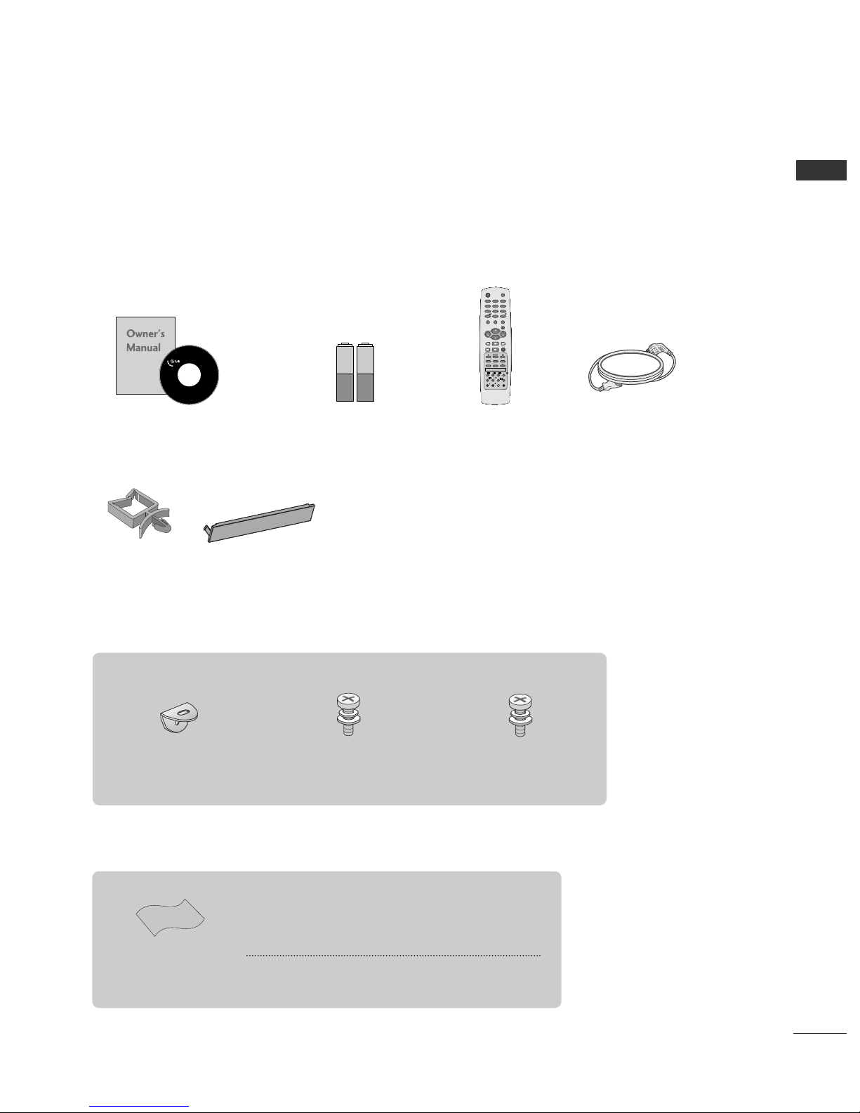
ACCESSORIES
Ensure that the following accessories are included with your TV. If an accessory is missing, please contact the
dealer where you purchased the product.
Batteries Remote Control Power Cord
2- TV Brackets
2- Wall Brackets
2-bolts
4-bolts for stand assembly
Refer to p. 6
ACCESSORIES
Polishing Cloth
Polish the screen with the cloth
This feature is not available
for all models.
*
Slightly wipe stained spot on the exterior only with the cleansing cloths for the product exterior if there is stain or fingerprint on
surface of the exterior.
Do not wipe roughly when removing stain. Please be cautious of
that excessive power may cause scratch or discoloration.
Owner’s Manual
OK
VOL
VOL
I/II
LIST
FAV
SLEEP
Q.VIEW
0
INPUT
MUTE
MENU
1
23
4
56
7
89
POWER
TV
PIP PR
RATIO EXIT
PIP PR
PIP INPUT
?
SIZE
i
TIME
HOLD
POSITION
REVEAL
INDEX TEXT
PIP
PR
PR
This feature is not available for all models.
Holder
(Refer to p.8)
Cover
(Refer to p.9)
Ofrecido por www.electromanuales.com
2
CONTENTS
CONTENTS
PREPARATION
Front Panel Controls....................................................... 4
Back Panel Information .................................................. 5
Stand Installation............................................................. 6
Attaching the TV to a Wall.............................................7
Back Cover for Wire Arrangement.............................. 8
Power Cord Arrangement.............................................. 8
Desktop Pedestal Installation....................................... 8
Wall Mount: Horizontal installation ............................ 9
Not Using The Desk-type Stand................................. 9
Antenna Connection .................................................... 10
PICTURE CONTROL
Watching PIP(Picture- in - Picture)............................41
Picture Size (Aspect Ratio)Control...........................43
Preset Picture Settings
- Picture Mode-Preset..............................................45
- Auto Colour Tone Control(Warm/Medium/Cool)
..46
Manual Picture Adjustment
- Picture Mode-User Option .................................47
- Colour Tone - User Option.................................48
-
Picture Improvement Technology
....................49
Demo...................................................................50
Advanced - Cinema ........................................................51
Advanced - Black(Darkness) Level.............................52
Picture Reset....................................................................53
Image Sticking Minimization(ISM) Method ............54
Low-Power Picture Mode..............................................55
Factory Reset
....................................................................
56
SOUND & LANGUAGE CONTROL
Auto Volume Leveler......................................................57
Preset Sound Settings - Sound Mode......................58
Sound Setting Adjustment - User Mode .................59
Balance..............................................................................60
TV Speakers On/Off Setup .........................................61
I/II
- Stereo/Dual Reception.........................................62
- NICAM Reception..................................................63
- Speaker Sound Output Selection......................63
On-Screen Menu Language /Country Selection
...... 64
EXTERNAL EQUIPMENT SETUP
HD Receiver Setup..........................................................11
DVD Setup....................................................................... 14
VCR Setup ........................................................................17
External Stereo ................................................................19
PC Setup...........................................................................20
- Screen Setup for PC Mode .................................22
WATCHING TV /PROGRAMME CONTROL
Remote Control Key Functions...................................26
Turning on the TV......................................................... 28
Programme Selection ................................................... 29
Volume Adjustment........................................................29
On Screen Menu Selection and Adjustment ..........30
Auto Programme Tuning.............................................. 31
Manual Programme Tuning ......................................... 32
Fine Tuning .......................................................................33
Assigning a Station Name............................................34
Programme Edit ............................................................. 35
Favourite Programme.................................................... 36
Calling the Programme Table ..................................... 37
Key lock ........................................................................... 38
.....................................................................39
PREPARATION
PICTURE CONTROL
WATCHING TV / PROGRAMME CONTROL
AACCCCEESSSSOORRIIEESS
......................................................1
Ofrecido por www.electromanuales.com

3
CONTENTS
APPENDIX
Troubleshooting..............................................................72
Maintenance ...................................................................74
Product Specifications..................................................75
TIME SETTING
Clock Setup .....................................................................65
Auto On/Off Timer Setting .........................................66
Sleep Timer Setting........................................................67
Auto Shut-off Setting ....................................................68
TELETEXT
Switch On/Off.................................................................69
SIMPLE Text .....................................................................69
TOP Text ...........................................................................70
FASTEXT...........................................................................70
Special Teletext Functions............................................71
Ofrecido por www.electromanuales.com
4
PREPARATION
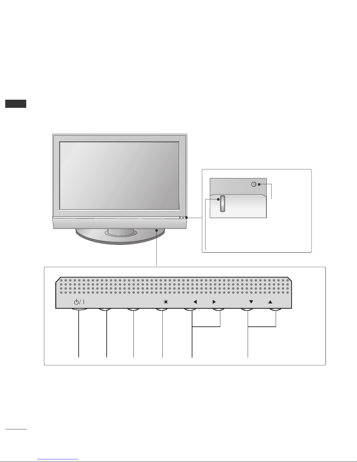
FRONT PANEL CONTROLS
PREPARATION
■
This is a simplified representation of the front panel. Here shown may be somewhat different from your TV.
■
If your product has a protection film attached, remove the film and then wipe the product with a polishing
cloth.
PROGRAMME
Buttons
VOLUME
Buttons
MENU
Button
OK
Button
INPUT
Button
POWER
Button
PR
VOL
OK
MENU
INPUT
Power/Standby Indicator
• illuminates red in standby mode.
• illuminates green when the set is switched on.
Remote Control
Sensor
Ofrecido por www.electromanuales.com
5
PREPARATION
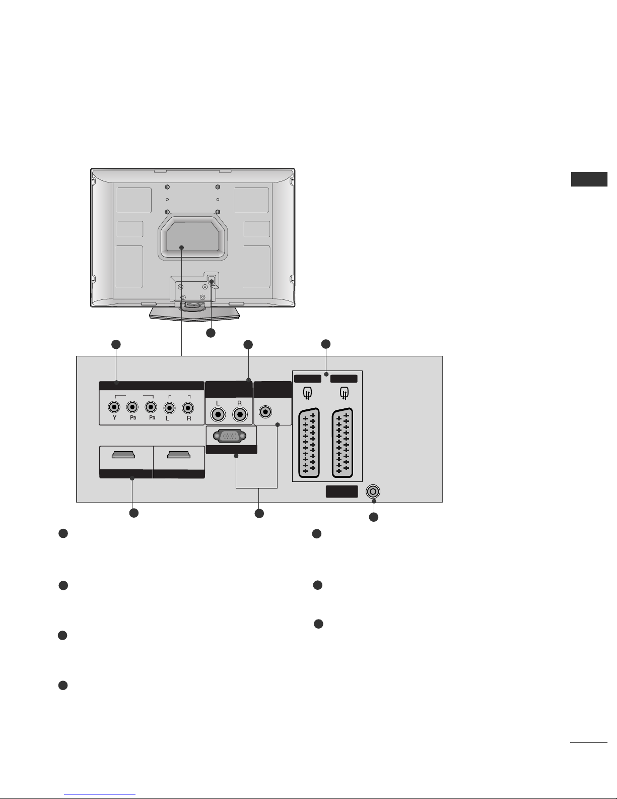
BACK PANEL INFROMATION
■
This is a simplified representation of the back panel. Here shown may be somewhat different from your TV.
Component Input
Connect a component video/audio device to
these jacks.
Variable Output
Connect an external amplifier or add a subwoofer
to your surround sound system.
Euro Scart Socket (AV1/AV2)
Connect scart socket input or output from an
external device to these jacks.
HDMI Input
Connect a HDMI signal to HDMI IN.
Or DVI(VIDEO)signal to HDMI/DVI port with DVI
to HDMI cable.
RGB/Audio Input
Connect the monitor output from a PC to the
appropriate input port.
Antenna Input
Connect over-the-air signals to this jack.
Power Cord Socket
This TV operates on an AC power. The voltage is
indicated on the Specifications page. Never
attempt to operate the TV on DC power.
1
2
3
4
5
6
7
AV 2 AV 1
ANTENNA
IN
HDMI/DVI IN
1 2
RGB IN(PC)
VIDEO
VIDEO
AUDIO
COMPONENT
COMPONENT
IN
VARIABLE
OUT
AUDIO IN
(RGB/DVI)
HDMI IN
2
1
4
6
3
5
7
Ofrecido por www.electromanuales.com

6
PREPARATION
PREPARATION
STAND INSTALLATION
1
2
3
Carefully place the product screen side down on
a cushioned surface that will protect product and
screen from damage.
Assemble the product stand with the product as
shown.
Install the 4 bolts securely, in the back of the
product in the holes provided.
Ofrecido por www.electromanuales.com

7
PREPARATION
ATTACHING THE TV TO A WALL
■
This feature is not available for all models.
■
Set it up close to the wall so the product doesn’t fall over when it is pushed backwards.
■
The instructions shown below is a safer way to set up the product, which is to fix it on the wall so the
product doesn’t fall over when it is pulled in the forward direction. It will prevent the product from
falling for-ward and hurting people. It will also prevent the product from damage caused by fall. Please
make sure that children don’t climb on or hang from the product.
NOTE
!
GG
When moving the product to another place undo the ropes first.
GG
Use a product holder or a cabinet that is big and strong enough for the size and weight of the product.
GG
To use the product safely make sure that the height of the bracket that is mounted on the wall is same as
that of the product.
3
1
2
Use the eye-bolts or TV brackets/bolts to fix the product to the wall as shown in the picture.
(If your product has the bolts in the TV brackets/bolts position before inserting the TV brackets/bolts, loosen
the bolts.)
* Insert the eye-bolts or TV brackets/bolts and tighten them securely in the upper holes.
Secure the wall brackets with the bolts (not provided as parts of the product, must purchase separately) on
the wall. Match the height of the bracket that is mounted on the wall.
3
Use a sturdy rope (not provided as parts of the product, must purchase separately) to tie the
product. It is safer to tie the rope so it becomes horizontal between the wall and the product.
2
1
Ofrecido por www.electromanuales.com

8
PREPARATION
BACK COVER FOR WIRE ARRANGEMENT
PREPARATION
DESKTOP PEDESTAL INSTALLATION
For proper ventilation, allow a clearance of 4inches on each side from the wall.
4 inches
4 inches
4 inches
4 inches
Arrange the cables as shown picture.
POWER CORD ARRANGEMENT
After connecting the power cord to the AC input
terminal, remove the bolt at the hole on the back
cover and fix the power cord at the rear side of the
TV by using the bracket for fixing the power cord.
Ofrecido por www.electromanuales.com

9
PREPARATION
■
The TV can be installed in various ways such as on a wall, or on a desktop etc.
■
The TV is designed to be mounted horizontally.
Power Supply
Short-circuit
Breaker
GROUNDING
Ensure that you connect the earth ground wire to prevent
possible electric shock. If grounding methods are not possible, have a qualified electrician install a separate circuit
breaker.
Do not try to ground the unit by connecting it to telephone wires, lightening rods, or gas pipes.
WALL MOUNT: HORIZONTAL INSTALLATION
For adequate ventilation allow a clearance of 4” (10cm) all around the TV. We recommend that you use a wall
mounting bracket of LG brand when mounting the TV to a wall.
4 inches
4 inches
4 inches
4 inches
4 inches
When installing the wall-mounted unit, use the protection
cover for desk-type stand installation.
NOT USING THE DESK-TYPE STAND
Ofrecido por www.electromanuales.com
ANTENNA
IN
10
PREPARATION
ANTENNA
IN
PREPARATION
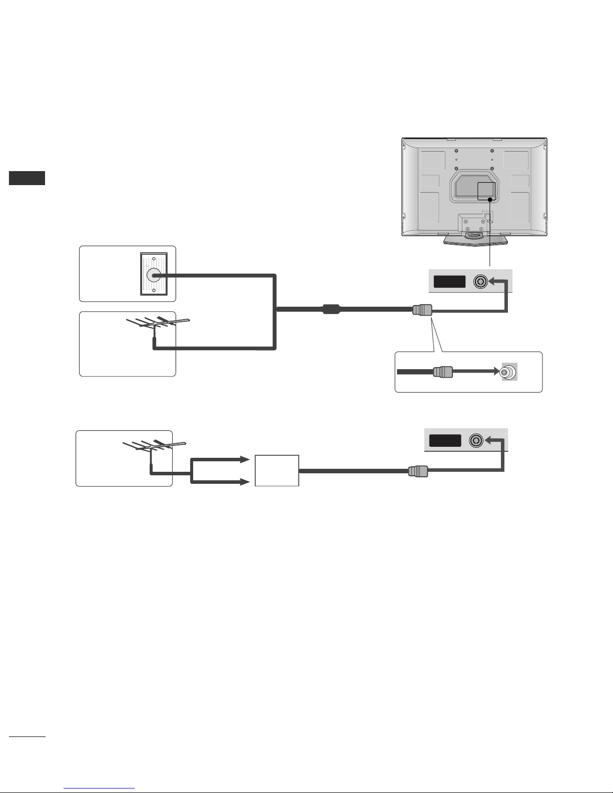
ANTENNA CONNECTION
■
For optimum picture quality, adjust antenna direction.
■
An antenna cable and converter are not supplied.
Multi-family Dwellings/Apartments
(Connect to wall antenna socket)
Single-family Dwellings /Houses
(Connect to wall jack for outdoor antenna)
Outdoor
Antenna
Antenna
Wall
Antenna
Socket
RF Coaxial Wire (75 ohm)
UHF
Signal
Amplifier
VHF
■
In poor signal areas,to get better picture quality, install a signal amplifier to the antenna as shown above.
■
If signal needs to be split for two TVs,use an antenna signal splitter for connection.
■
To prevent the equipment damage, never plug in any power cords until you have finished connecting all equipment.
Ofrecido por www.electromanuales.com
11
EXTERNAL EQUIPMENT SETUP
EXTERNAL EQUIPMENT SETUP
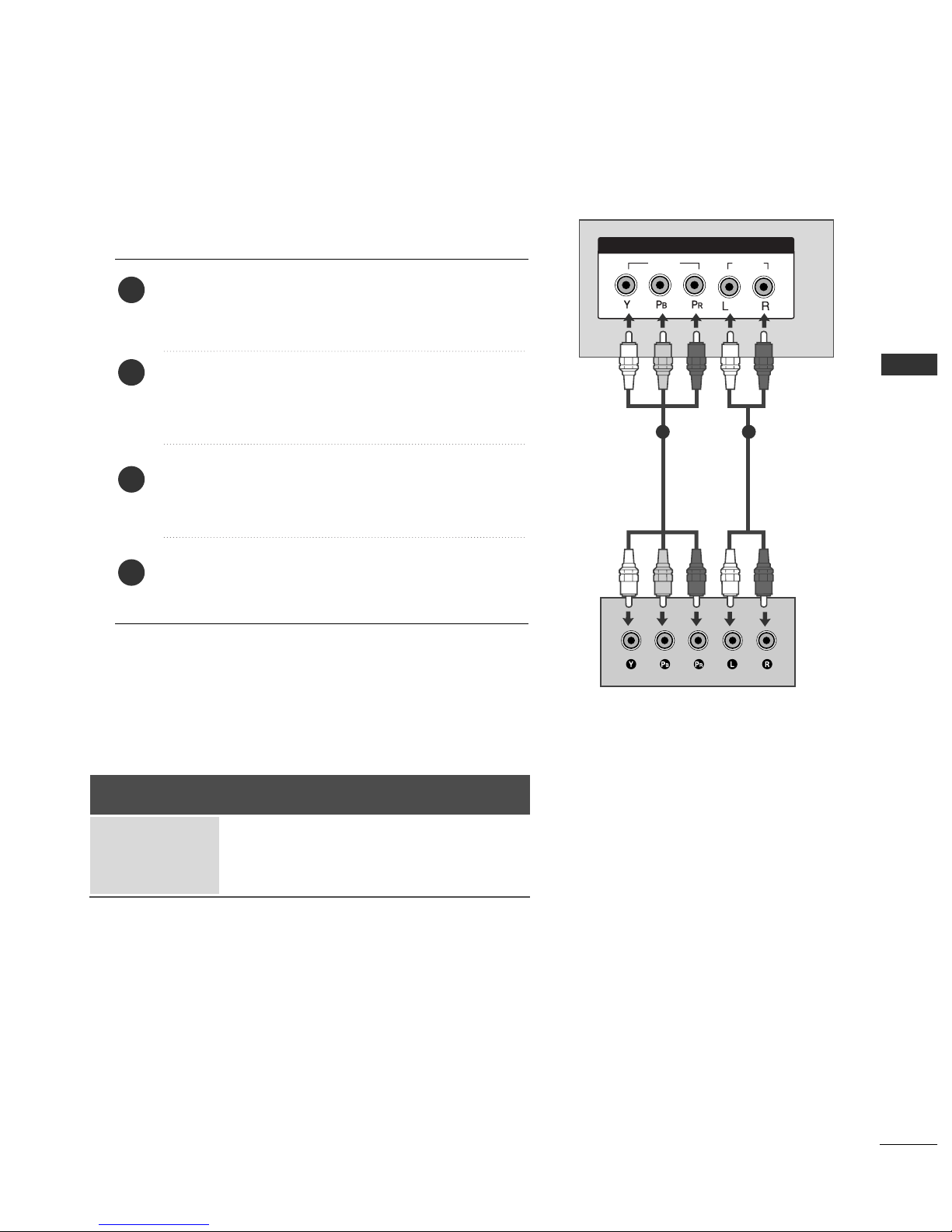
HD RECEIVER SETUP
VIDEOVIDEO
AUDIOAUDIO
COMPONENT IN
1
HDMI IN
HDMI/DVI IN
When connecting with a component cable
Connect the video outputs (Y, PB
, PR
)
of the digital set
top box to the
CCOOMMPPOONNEE NNTT IINN VVIIDD EEOO
jacks on the
set.
Connect the audio output of the digital set-top box to
the
CCOOMMPPOONNEE NNTT IINN AA UUDDIIOO
jacks on the set.
Turn on the digital set-top box.
(
Refer to the owner’s manual for the digital set-top box.
)
Select
Component input source with using the
IINNPPUUTT
button on the remote control.
2
3
4
1
1 2
■
To prevent the equipment damage, never plug in any power cords until you have finished connecting all equipment.
Signal
480i/576i
480p/576p
720p/1080i
Component
Yes
Yes
Yes
HDMI1/2
No
Yes
Yes
Ofrecido por www.electromanuales.com

12
EXTERNAL EQUIPMENT SETUP
EXTERNAL EQUIPMENT SETUP
VIDEO
AUDIO
COMPONENT IN
HDMI IN
1 2
1
HDMI IN
HDMI/DVI IN
HDMI/DVI IN
When connecting with a HDMI cable
Connect the HDMI output of the digital set-top box to
the
HH DDMMII//DDVV II IINN 11
or
HH DDMMII IINN 22
jack on the set.
Select
HDMI1 or HDMI2 input source with using the
IINN PPUUTT
button on the remote control.
Turn on the digital set-top box.
(
Refer to the owner’s manual for the digital set-top box.
)
2
3
1
GG
TV can receive the video and audio signal simultaneously
with using a HDMI cable.
GG
If the digital set-top box supports Auto HDMI function, the
output resolution of the source device will be automatically
set to 1280x720p.
GG
If the digital set-top box player does not support Auto
HDMI, you need to set the output resolution appropriately.
To get the best picture quality, adjust the output resolution
of the source device to 1280x720p.
NOTE
!
1
Resolution
720x480p
720x576p
1280x720p
1920x1080i
Supported Display Resolution (HDMI-DTV mode)
Horizontal Vertical
Frequency(kHz) Frequency(Hz)
31.47 59.94
31.50 60.00
31.25 50.00
44.96 59.94
45.00 60.00
37.50 50.00
33.72 59.94
33.75 60.00
28.125 50.00
Ofrecido por www.electromanuales.com

13
EXTERNAL EQUIPMENT SETUP
1
RGB IN(PC)
VIDEO
AUDIO
COMPONENT IN
VARIABLE
OUT
HDMI INHDMI IN
AUDIO IN
(RGB/DVI)
HDMI/DVI INHDMI/DVI IN
1
2
Connect the DVI output of the digital set-top box to the
HH DDMMII//DDVV II IINN 11
jack on the set.
Connect the audio output of the digital set-top box to the
AAUUDD II OO IINN((RRGG BB //DDVVII))
jack on the set.
Turn on the digital set-top box. (Refer to the owner’s manual for the digital set-top box.
)
Select
HDMI1 input source with using the
IINN PPUUTT
button on the remote control.
2
3
4
1
When connecting with a HDMI to DVI cable
Ofrecido por www.electromanuales.com
14
EXTERNAL EQUIPMENT SETUP
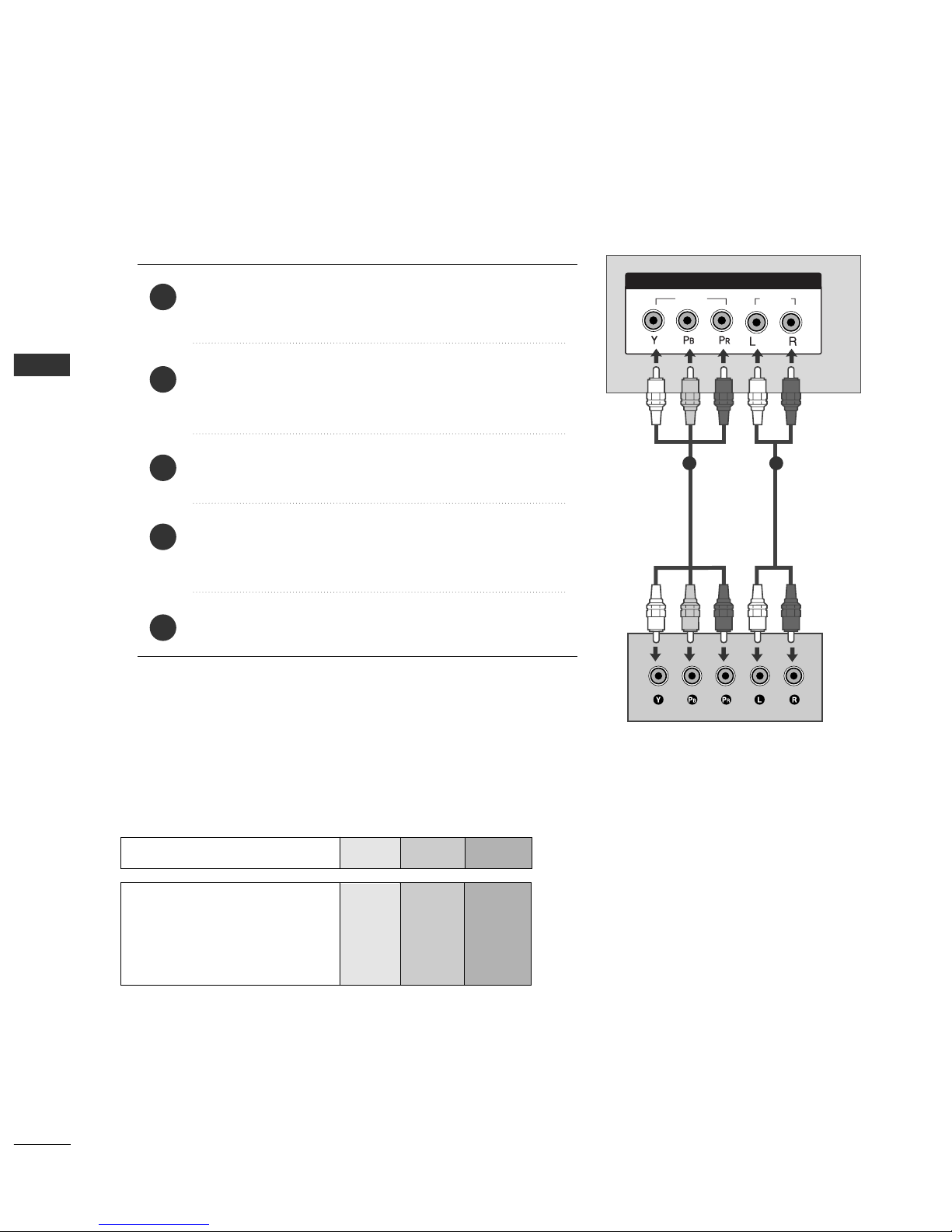
DVD SETUP
EXTERNAL EQUIPMENT SETUP
When connecting with a component cable
VIDEOVIDEO
AUDIOAUDIO
COMPONENT IN
AV 2 AV 1
Component Input ports
To get better picture quality, connect a DVD player to the component input ports as shown below.
Component ports on the TV
YPB PR
Video output ports
on DVD player
Y
Y
Y
Y
PB
B-Y
Cb
Pb
P
R
R-Y
Cr
Pr
Connect the video outputs (Y, PB
, PR
)
of the DVD to the
CCOOMMPPOONNEENNTT II NN VVIIDDEE OO
jacks on the set.
Connect the audio outputs of the DVD to the
CCOOMM PPOO--
NNEENN TT II NN AAUUDD II OO
jacks on the set.
Turn on the DVD player, insert a DVD.
Select
Component input source with using the
IINN PPUUTT
button on the remote control.
Refer to the DVD player's manual for operating instructions.
2
3
4
5
1
1 2
Ofrecido por www.electromanuales.com
15
EXTERNAL EQUIPMENT SETUP
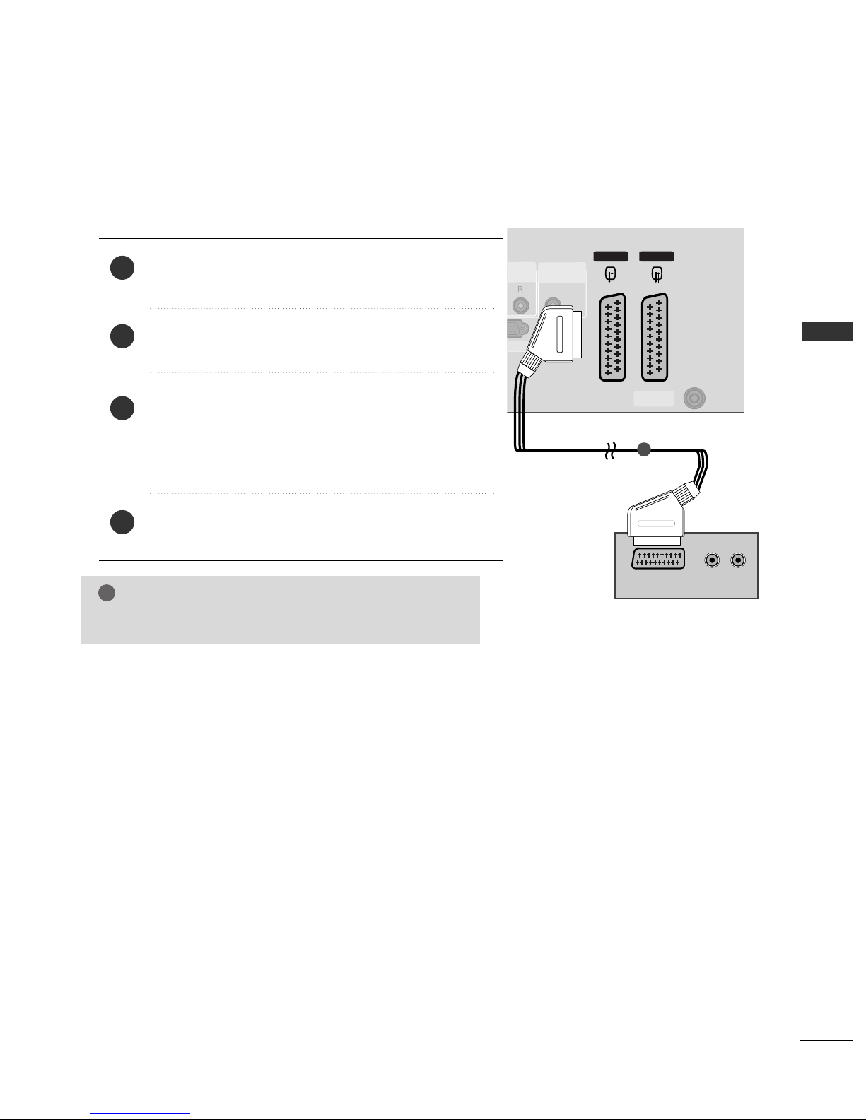
When connecting with a Euro Scart
Connect the Euro scart socket of the DVD to the
AA VV 11
Euro
scart socket on the set.
Turn on the DVD player, insert a DVD.
Select
AV 1 input source with using the
IINN PPUUTT
button on
the remote control.
If connected to
AV 2 Euro scart socket, select AV 2 input
source.
Refer to the DVD player's manual for operating instructions.
2
3
4
1
AV 2 AV 1
ANTENNA
IN
HDMI IN
12
RGB IN(PC)
VIDEO
AUDIO
COMPONENT IN
AV 2V 2 AV 1
ANTENNA
IN
AUDIO IN
(RGB/DVI)
IN(PC)
(R) AUDIO (L)
AUDIO/
VIDEO
1
NOTE
!
GG
Please use the shield scart cable.
Ofrecido por www.electromanuales.com

16
EXTERNAL EQUIPMENT SETUP
EXTERNAL EQUIPMENT SETUP
VIDEO
AUDIO
COMPONENT IN
AV 2 AV 1
HDMI IN
1 2
HDMI/DVI IN
When connecting HDMI cable
Connect the HDMI output of the DVD to the
HH DDMMII//DDVV II IINN 11
or
HH DDMMII IINN 22
jack on the set.
Select
HDMI1 or HDMI2 input source with using
the
IINN PPUUTT
button on the remote control.
Refer to the DVD player's manual for operating
instructions.
1
GG
TV can receive the video and audio signal simultaneously
with using a HDMI cable.
GG
If the DVD supports Auto HDMI function, the output resolution of the source device will be automatically set to
1280x720p.
GG
If the DVD player does not support Auto HDMI, you need to
set the DVD output resolution appropriately.
To get the best picture quality, adjust the output resolution
of the source device to 1280x720p.
NOTE
!
1
2
3
Ofrecido por www.electromanuales.com

17
EXTERNAL EQUIPMENT SETUP
VCR SETUP
When connecting with an antenna
■
To avoid picture noise (interference), leave an adequate distance between the VCR and TV.
■
Typically a frozen still picture from a VCR. If the 4:3 picture format is used; the fixed images on the sides of
the screen may remain visible on the screen.
ANTENNA
IN
OUTPUT
SWITCH
ANT IN
R
S-VIDEO VIDEO
ANT OUT
L
Wall Jack
Antenna
Connect the
AANNTT OOUUTT
socket of the VCR to the
AANNTTEENNNNAA IINN
socket on the set.
Connect the antenna cable to the
AA NNTT IINN
socket of the VCR.
Press the
PP LLAAYY
button on the VCR and match the appropriate programme between the TV and VCR for
viewing.
1
2
2
3
1
Ofrecido por www.electromanuales.com

18
EXTERNAL EQUIPMENT SETUP
EXTERNAL EQUIPMENT SETUP
When connecting with a Euro Scart
Connect the Euro scart socket of the VCR to the
AA VV 11
Euro
scart socket on the set.
Insert a video tape into the VCR and press PLAY on the
VCR. (Refer to the VCR owner’s manual.)
Select
AV 1 input source with using the
IINN PPUUTT
button
on the remote control.
If connected to
AA VV 22
Euro scart socket, select
AV 2 input
source.
2
3
1
ANTENNA
IN
AV 2 AV 1 V 1
ANTENNA
IN
AUDIO IN
(RGB/DVI)
IN(PC)
(R) AUDIO (L)
AUDIO/
VIDEO
1
NOTE
!
GG
If you want to use the EURO scart cable, you have to use the
signal shielded Euro scart cable.
Ofrecido por www.electromanuales.com
19
EXTERNAL EQUIPMENT SETUP
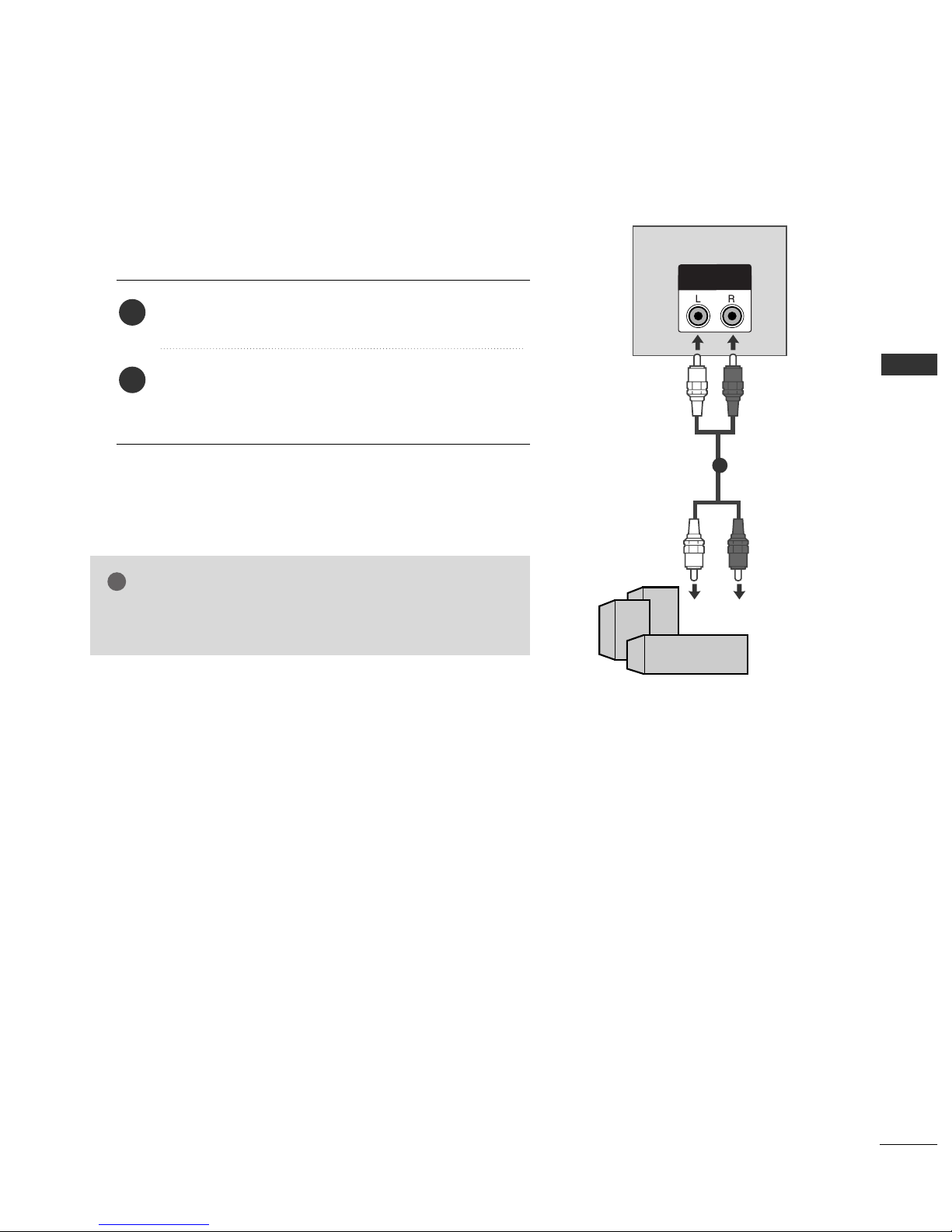
EXTERNAL STEREO
VARIABLE
OUT
GG
When connecting with external audio equipments, such as amplifiers or speakers, please turn the TV speakers off.(
GG
p.61)
NOTE
!
Use to connected either an external amplifier, or add a subwoofer to your surround sound system.
Connect the input jack of the stereo amplifier to the
VV AARRIIAABBLL EE OOUUTT
jacks on the set.
Set up your speakers through your analog stereo
amplifier, according to the instructions provided with
the amplifier.
2
1
11
Ofrecido por www.electromanuales.com
20
EXTERNAL EQUIPMENT SETUP
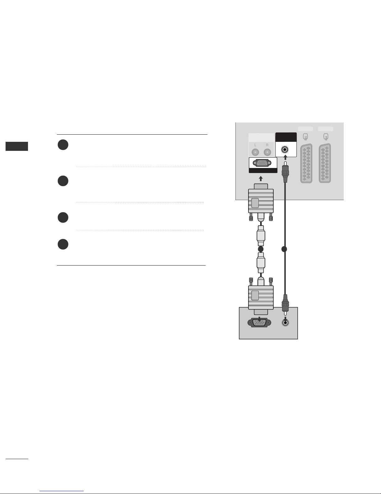
PC SETUP
EXTERNAL EQUIPMENT SETUP
This TV provides Plug and Play capability, meaning that the PC adjusts automatically to the TV's settings.
When connecting with a D-sub 15 pin cable
RGB IN(PC)
AUDIO IN
(RGB/DVI)
VARIABLE
OUT
AV 2 AV 1
RGB OUTPUT
AUDIO
Connect the RGB output of the PC to the
RR GG BB
IINN((PP CC
))
jack on the set.
Connect the PC audio output to the
AAUUDD IIOO IINN
((RRGGBB //DDVVII))
jack on the set.
Turn on the PC and the set.
Select
RGB PC input source with using the
IINNPPUUTT
button on the remote control.
2
3
4
1
1
2
Ofrecido por www.electromanuales.com
21
EXTERNAL EQUIPMENT SETUP
NOTE
!
GG
To enjoy vivid picture and sound,connect a PC to
the set.
GG
Avoid keeping a fixed image on the set ’s screen
for a long period of time.The fixed image may
become permanently imprinted on the
screen;use a screen saver when possible.
GG
Connect PC to the RGB (PC) port of the
set;change the resolution output of PC accordingly.
GG
There might be noise according to some resolu-
tion,vertical pattern,contrast or brightness in PC
mode.Change the PC mode into another resolution or change the refresh rate into another rate
or adjust the brightness and contrast on the
menu until the picture is clean.If the refresh rate
of the PC graphic card can not be changed,
change the PC graphic card or consult it to the
manufacturer of the PC graphic card.
GG
The synchronization input waveform for
Horizontal and Vertical frequencies are separate.
GG
We recommend using 852x480, 60Hz for the
PC mode, they provide the best picture quality.
GG
If the resolution of PC is over XGA, there will be
no picture on the set.
GG
Connect the audio cable from the PC to the
Audio input on the set.(Audio cables are not
included with the set).
GG
When you use too long RGB-PC cable,there
might be a noise on the screen.We recommend
using under 5m of the cable.It provides the best
picture quality.
GG
The set dose not support DVI-PC mode.
NOTE
!
GG
It’s supported to 848x480, 852x480 in VGA
modes. (VGA Models)
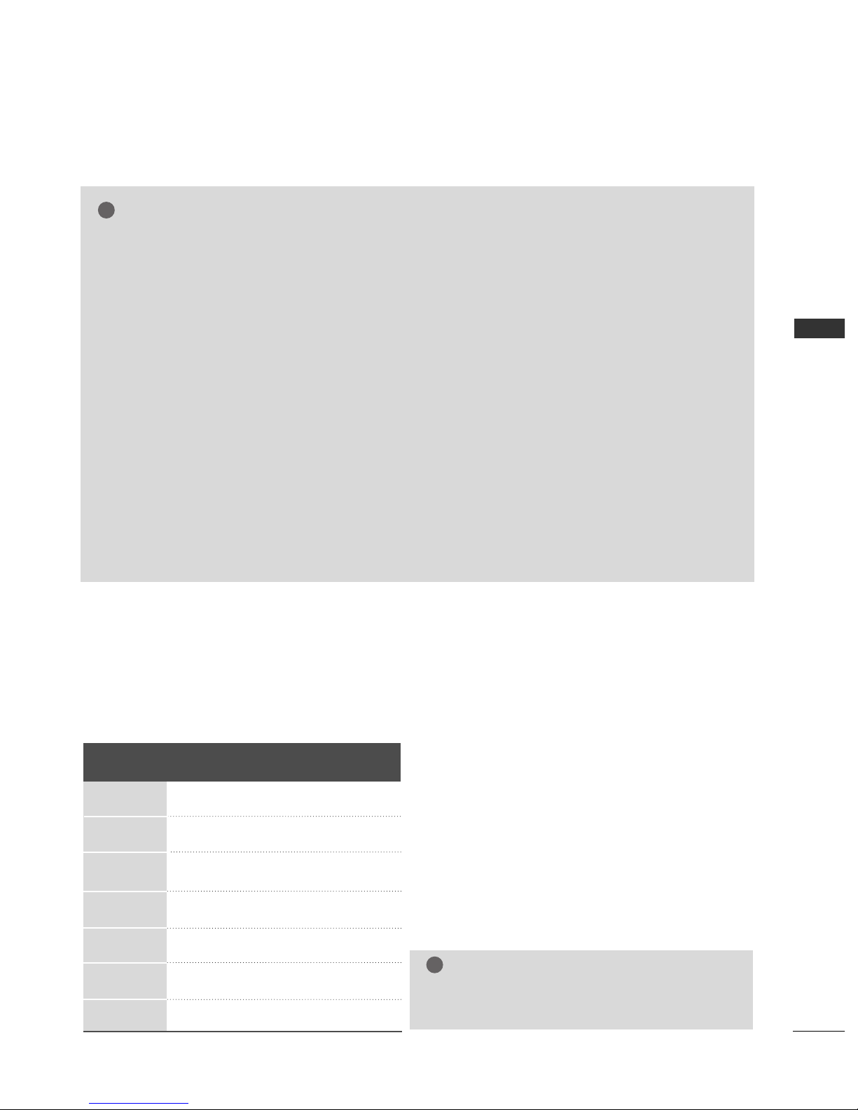
Resolution
640x350
720x400
640x480
848x480
852x480
800x600
1024x768
Supported Display Resolution (RGB-PC mode)
Horizontal Vertical
Frequency(kHz) Frequency(Hz)
31.468 70.09
31.469 70.08
31.469 59.94
31.5 60.0
31.5 60.0
37.879 60.31
48.363 60.0
Ofrecido por www.electromanuales.com

22
EXTERNAL EQUIPMENT SETUP
EXTERNAL EQUIPMENT SETUP
Press the
MMEENN UU
button and then use
DD
//
EE
button to
select the
Picture menu.
Press the
GG
button and then use
DD
//
EE
button to select
Screen.
Press the
GG
button and then use
DD
//
EE
button to select
Auto Config..
Press the
GG
button to start Auto Config..
• When Auto config. has finished, OK will be shown on
screen.
• If the position of the image is still not correct, try Auto
adjustment again.
• If picture needs to be adjusted more after Auto adjustment in RGB (PC), you can adjust the
Manual Config..
Press the
EE XXIITT
button to return to TV viewing.
Automatically adjusts picture position and minimizes image
shaking. After adjustment, if the image is still not correct, your
set is functioning properly but needs further adjustment.
AAuu ttoo ccoo nnff iigg uurree
This function is for the automatic adjustment of the screen
position, clock, and phase. The displayed image will unstable for
a few seconds while the auto configuration is in progress.
1
2
3
4
5
1
3 4
Screen Setup for PC mode
Auto Configure (RGB [PC] mode only)
Picture Mode
Colour Temperature
XD
Advanced
Aspect Ratio
Picture Reset
Screen
XD Demo
Picture
Screen
Auto config.
Manual Config.
VGA Mode
Reset
To Set
Auto Config. G
DE F G
OK MENU
2
Picture
Picture Mode
Colour Temperature
XD
Advanced
Aspect Ratio
Picture Reset
Screen
XD Demo
To Set
Screen G
DE F G
OK MENU
DE F G
OK MENU
OK
VOL
VOL
MENU
1
23
4
56
7
89
POWER
TV
0
INPUT
MUTE
RATIO
EXIT
PR
PR
Ofrecido por www.electromanuales.com
 Loading...