

Page 1

OWNER’S MANUAL
Safety and Reference
LED TV*
* LG LED TVs are LCD TVs with LED backlighting.
Please read this manual carefully before operating
your TV and retain it for future reference.
32LW300C 43LW540S
49LW540S
55LW540S
*MFL69412011*
32LW340C
43LW340C
49LW340C
55LW340C
32LW340H
43LW340H
49LW340H
55LW340H
www.lg.com
P/NO : MFL69412011 (1609-REV02)
Page 2
Important Safety Instructions
Always comply with the following precautions
to avoid dangerous situations and ensure peak
performance of your product.
WARNING/CAUTION
RISK OF ELECTRIC SHOCK
DO NOT OPEN
TO REDUCE THE RISK OF ELECTRIC SHOCK
DO NOT REMOVE COVER (OR BACK). NO
USER SERVICEABLE PARTS INSIDE. REFER TO
QUALIFIED SERVICE PERSONNEL.
The lightning flash with arrowhead
symbol within an equilateral triangle is
intended to alert the user to the presence of
uninsulated dangerous voltage within the
product’s enclosure that may be of sufficient
magnitude to constitute a risk of electric shock
to persons.
The exclamation point within an
equilateral triangle is intended to alert the
user to the presence of important operating
ENGLISH
and maintenance (servicing) instructions in
the literature accompanying the device.
WARNING/CAUTION
- TO REDUCE THE RISK OF FIRE AND ELECTRIC
SHOCK, DO NOT EXPOSE THIS PRODUCT TO
RAIN OR MOISTURE.
WARNING
If you ignore the warning message, you may
be seriously injured or there is a possibility of
accident or death.
CAUTION
If you ignore the caution message, you may
be slightly injured or the product may be
damaged.
NOTE
The note helps you understand and use the
product safely. Please read the note carefully
before using the product.
Read these instructions.
Keep these instructions.
Heed all warnings.
Follow all instructions.
• Do not use this apparatus near water.
• Clean only with dry cloth.
• Do not block any ventilation openings. Install in
accordance with the manufacturer’s instructions.
• Do not install near any heat sources such
as radiators, heat registers, stoves, or other
apparatus (including amplifiers) that produce
heat.
• Do not defeat the safety purpose of the
polarized or grounding-type plug. A polarized
plug has two blades with one wider than the
other. A grounding type plug has two blades
and a third grounding prong. The wide blade or
the third prong are provided for your safety. If
the provided plug does not fit into your outlet,
consult an electrician for replacement of the
obsolete outlet.
• Protect the power cord from being walked on
or pinched particularly at plugs, convenience
receptacles, and the point where they exit from
the apparatus.
2
Page 3
• Only use attachments/accessories specified by
the manufacturer.
• Use only with a cart, stand, tripod, bracket, or
table specified by the manufacturer, or sold with
the apparatus. When a cart is used, use caution
when moving the cart/apparatus combination to
avoid injury from tip-over.
• Unplug this apparatus during lightning storms
or when unused for long periods of time.
• Refer all servicing to qualified service personnel.
Servicing is required when the apparatus has
been damaged in any way, such as power-supply
cord or plug is damaged, liquid has been spilled
or objects have fallen into the apparatus, the
apparatus has been exposed to rain or moisture,
does not operate normally, or has been dropped.
• Do not apply pressure on the panel during
handling or a sharp object such as a nail, pencil,
or pen, or make a scratch on it.
• CAUTION concerning the Power Cord
(Can differ by country):
Check the specification page of this owner’s
manual to be certain concerning current
requirements. Do not connect too many
devices to the same AC power outlet as this
could result in fire or electric shock. Do not
overload wall outlets. Overloaded wall outlets,
loose or damaged wall outlets, extension cords,
frayed power cords, or damaged or cracked
wire insulation are dangerous. Any of these
conditions could result in electric shock or fire.
Periodically examine the cord of your device,
and if its appearance indicates damage or
deterioration, unplug it, discontinue use of
the device, and have the cord replaced with
an exact replacement part by an authorized
servicer. Protect the power cord from physical or
mechanical abuse, such as being twisted, kinked,
pinched, closed in a door, or walked upon. Pay
particular attention to plugs, wall outlets, and
the point where the cord exits the device. Do not
move the TV with the power cord plugged in. Do
not use a damaged or loose power cord. Be sure
do grasp the plug when unplugging the power
cord. Do not pull on the power cord to unplug
the TV.
• Warning - To reduce the risk of fire or electrical
shock, do not expose this product to rain,
moisture or other liquids. Do not touch the TV
with wet hands. Do not install this product near
flammable objects such as gasoline or candles,
or expose the TV to direct air conditioning.
ENGLISH
• Do not stick metal objects or any other
conductive material into the power cord. Do
not touch the end of the power cord while it is
plugged in.
• Keep the packing anti-moisture material or
vinyl packing out of the reach of children.
Anti-moisture material is harmful if swallowed.
If swallowed, induce vomiting and go to the
nearest hospital. Additionally, vinyl packing can
cause suffocation. Keep it out of the reach of
children.
• Do not expose to dripping or splashing and
do not place objects filled with liquids, such as
vases, cups, etc. on or over the apparatus (e.g.,
on shelves above the unit).
3
Page 4
• Grounding
(Except for devices which are not grounded.)
Ensure that you connect the earth ground wire
to prevent possible electric shock (i.e., a TV
with a three-prong grounded AC plug must
be connected to a three-prong grounded AC
outlet). If grounding methods are not possible,
have a qualified electrician install a separate
circuit breaker. Do not try to ground the unit by
connecting it to telephone wires, lightning rods,
or gas pipes.
Power
Supply
Circuit
Breaker
• As long as this unit is connected to the AC wall
outlet, it is not disconnected from the AC power
source even if the unit is turned off.
• Do not attempt to modify this product in any
way without written authorization from LG
Electronics. Unauthorized modification could
void the user’s authority to operate this product.
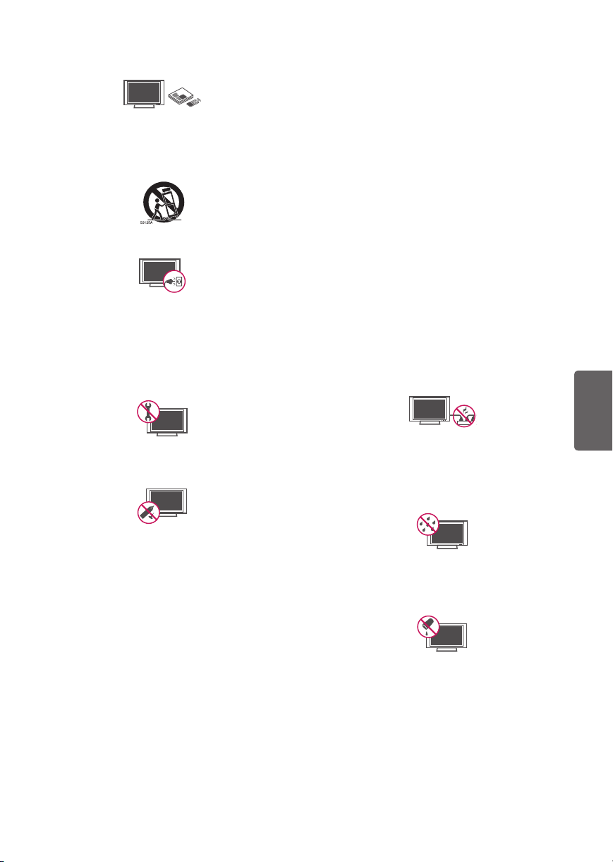
• Outdoor Antenna Grounding
(Can differ by country):
If an outdoor antenna is installed, follow the
precautions below. An outdoor antenna system
ENGLISH
should not be located in the vicinity of overhead
power lines or other electric light or power
circuits, or where it can come in contact with
such power lines or circuits as death or serious
injury can occur. Be sure the antenna system is
grounded to provide some protection against
voltage surges and built-up static charges.
Section 810 of the National Electrical Code (NEC)
in the U.S.A. provides information with respect
to proper grounding of the mast and supporting
structure, grounding of the lead-in wire to
an antenna discharge unit, size of grounding
conductors, location of antenna discharge
unit, connection to grounding electrodes and
requirements for the grounding electrode.
Antenna grounding according to the National
Electrical Code, ANSI/NFPA 70
• Cleaning
When cleaning, unplug the power cord and wipe
gently with a soft cloth to prevent scratching. Do
not spray water or other liquids directly on the
TV as electric shock may occur. Do not clean with
chemicals such as alcohol, thinners, or benzene.
• Moving
Make sure the product is turned off, unplugged,
and all cables have been removed. It may take 2
or more people to carry larger TVs. Do not press
or put stress on the front panel of the TV.
• Ventilation
Install your TV where there is proper ventilation.
Do not install in a confined space such as a
bookcase. Do not cover the product with cloth or
other materials while plugged. Do not install in
excessively dusty places.
• If you smell smoke or other odors coming from
the TV, unplug the power cord and contact an
authorized service center.
• If water or another substance enters the
product (like an AC adapter, power cord, or TV),
disconnect the power cord and contact the
service center immediately. Otherwise, this may
result in fire or electric shock.
• Use only an authorized AC adapter and power
cord approved by LG Electronics.
Otherwise, this may result in fire, electric shock,
malfunction, or product deformation.
• Never disassemble the AC adapter or power
cord. This may result in fire or electric shock.
4
Ground Clamp
Electric Service
Equipment
Ground Clamp
NEC: National Electrical Code
Antenna Lead in Wire
Antenna Discharge Unit
(NEC Section 810-20)
Grounding Conductor
(NEC Section 810-21)
Power Service Grounding
Electrode System
(NEC Art 250, Part H)
• Handle the adapter carefully to avoid dropping
or striking it. An impact could damage the
adapter.
Page 5

• Keep the product away from direct sunlight.
• Never touch this apparatus or antenna during a
lightning storm.
• When mounting a TV on the wall, make sure not
to install the TV by hanging the power and signal
cables on the back of the TV.
• Do not allow an impact shock, any objects to fall
into the product, and do not drop anything onto
the screen.
• DISCONNECTING THE DEVICE FROM THE MAIN
POWER
The power plug is the disconnecting device.
In case of an emergency, the power plug must
remain readily accessible.
• Batteries
Store the accessories (battery, etc.) in a safe
location out of the reach of children.
• This apparatus uses batteries. In your community
there might be regulations that require you
to dispose of these batteries properly due to
environmental considerations. Please contact
your local authorities for disposal or recycling
information.
• Do not dispose of batteries in a fire.
• Do not short circuit, disassemble, or allow the
batteries to overheat.
• Do not use high voltage electrical equipment
near the TV, (e.g., a bug zapper.)
This may result in product malfunction.
• Dot Defect
This panel is an advanced product that contains
millions of pixels. In a very few cases, you could
see fine dots on the screen while you’re viewing
the TV. Those dots are deactivated pixels and
do not affect the performance and reliability of
the TV.
• Generated Sound
Cracking noise A cracking noise that occurs
when watching or turning off the TV is
generated by plastic thermal contraction due to
temperature and humidity. This noise is common
for products where thermal deformation is
required.
Electrical circuit humming/panel buzzing
A low level noise is generated from a highspeed switching circuit, which supplies a large
amount of current to operate a product. It varies
depending upon the product. This generated
sound does not affect the performance and
reliability of the product.
• Take care not to touch the ventilation openings.
When watching the TV for a long period, the
ventilation openings may become hot. This does
not affect the performance of the product or
cause defects in the product.
• Do not install this product on a wall if it could be
exposed to oil or oil mist. This may damage the
product and cause it to fall.
• If the TV feels cold to the touch, there may
be a small flicker when it is turned on. This is
normal; there is nothing wrong with TV. Some
minute dot defects may be visible on the screen,
appearing as tiny red, green, or blue spots.
However, they have no adverse effect on the TV’s
performance. Avoid touching the LCD screen or
holding your finger(s) against it for long periods
of time. Doing so may produce some temporary
distortion effects on the screen.
• Displaying a still image for a prolonged period of
time may cause an image sticking.
Avoid displaying a fixed image on the TV screen
for a extended length of time.
ENGLISH
5
Page 6
Preparing
NOTE
• Image shown may differ from your TV.
• Your TV’s OSD (On Screen Display) may differ
slightly from that shown in this manual.
• The available menus and options may differ from
the input source or product model that you are
using.
• New features may be added to this TV in the
future.
• The items supplied with your product may vary
depending upon the model.
• Product specifications or contents of this manual
may be changed without prior notice due to
upgrade of product functions.
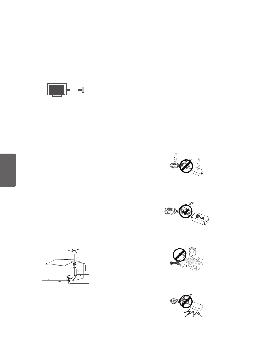
• For an optimal connection, HDMI cables and
USB devices should have bezels less than 10 mm
(0.39 inches) thick and 18 mm (0.7 inches) width.
• Use an extension cable that supports USB 2.0 if
the USB cable or USB flash drive does not fit into
your TV’s USB port.
• Use a certified cable with the HDMI logo
attached. If you do not use a certified HDMI
ENGLISH
cable, the screen may not display or a
connection error may occur.
• Recommended HDMI cable types (3m or less)
- High-Speed HDMI®/™ cable
- High-Speed HDMI®/™ cable with Ethernet
B
A
*A 10 mm (0.39 inches)
*B 18 mm (0.7 inches)
B
CAUTION
• Do not use any unapproved items to ensure the
safety and lifespan of the product.
• Any damages or injuries by using unapproved
items are not covered by the warranty.
• Some models appear to have a thin film on the
screen. It is actually part of the screen; do not
remove it.
• When attaching the stand to the TV set, place
the screen facing down on a cushioned table or
flat surface to protect the screen from scratches.
• Make sure that the screws are fastened tightly.
(If they are not fastened securely enough, the TV
may tilt forward after being installed.)
• Do not fasten the screws with excessive force
otherwise they may be worn out and become
loose.
Warning when using USB storage
devices
• USB storage devices with a built-in auto
recognition program or its own driver may not
work.
• Some USB storage devices may not work or may
work improperly.
• Use only those USB storage devices formatted
with FAT32 or NTFS File System provided by
Windows.
• For external USB HDD, use devices with less than
5V-rated voltages and 500 mA-rated current.
• It is recommended to use USB flash drive with 32
GB or less and USB HDD with 2 TB or less.
• If a USB HDD with power-saving function does
not work properly, turn the power off and on.
For more information, refer to the user manual
A
of USB HDD.
• Data in the USB storage device can be damaged
so back up important files in other devices. Data
maintenance is the user’s responsibility. The
manufacturer is not responsible for data loss.
Optional Extras
Optional extras can be changed or modified for
quality improvement without any notification.
Contact your dealer for buying these items.
These devices work only with certain models.
The model name or design may be changed due to
the manufacturer’s circumstances or policies.
(Depending upon model)
AN-WF500
Wi-Fi/Bluetooth Dongle
6
Page 7
Lifting and Moving the TV
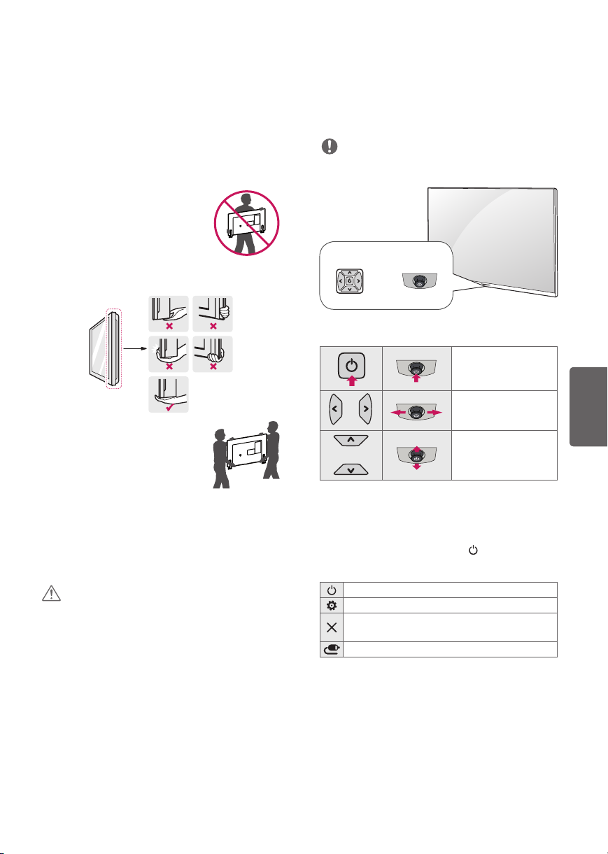
Dome Button
Or
Joystick Button
Using the Button
When moving or lifting the TV, read the following
to prevent the TV from being scratched or
damaged and for safe transportation regardless of
its type and size.
• It is recommended to move the TV in the box or
packing material that the TV originally came in.
• Before moving or lifting the TV, disconnect the
power cord and all cables.
• When holding the TV, the screen
should face away from you to
avoid damage.
• Hold the top and bottom of the TV frame firmly.
Make sure not to hold the transparent part,
speaker, or speaker grille area.
• Use at least two people to move
a large TV.
• When transporting the TV by
hand, hold the TV as shown in the
following illustration.
• When transporting the TV, do not expose the TV
to jolts or excessive vibration.
• When transporting the TV, keep the TV upright;
never turn the TV on its side or tilt towards the
left or right.
• When handling the TV, be careful not to damage
the protruding buttons.
CAUTION
• Avoid touching the screen at all times, as this
may result in damage to the screen.
• Do not place the product on the floor with its
front facing down without padding. Failure to do
so may result in damage to the screen.
• Do not move the TV by holding the cable
holders, as the cable holders may break, and
injuries and damage to the TV may occur.
(Depending upon model)
(Depending upon model)
You can simply operate the TV functions, pressing
or moving the button.
NOTE
• LW300C series does not have a Joystick button
but it only has a power on/off button.
Basic Functions
Power On (Press)
Power Off
(Press and Hold)
Volume Control
Channels Control
1 If the menu button is on the screen, pressing and
holding the joystick button will let you exit the menu.
Adjusting the Menu
When the TV is turned on, press button one
time. You can adjust the Menu items pressing or
moving the buttons.
Turns the power off.
Accesses the settings menu.
Clears on-screen displays and returns to TV
viewing.
Changes the input source.
ENGLISH
7
Page 8
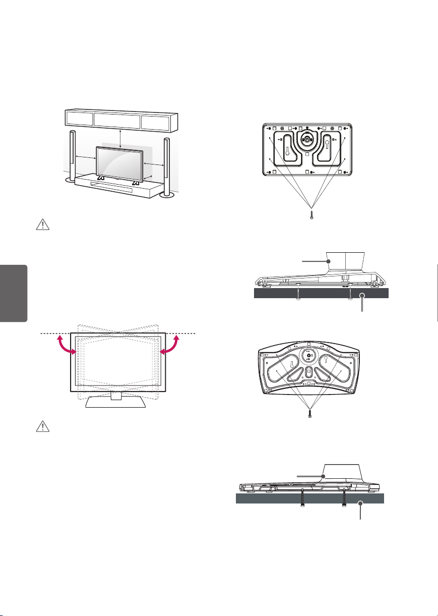
Mounting on a Table
1 Lift and tilt the TV into its upright position on a
table.
- Leave a 10 cm (4 inches) (minimum) space from
the wall for proper ventilation.
10 cm
10 cm
2 Connect the power cord to a wall outlet.
(4 inches)
10 cm
10 cm
Attaching the TV to a desk (optional)
(Depending upon model)
The TV should be attached to a desk so it cannot
be pulled in a forward/backward direction,
potentially causing injury or damaging the
product.
[TYPE 1-1]
CAUTION
• Do not place the TV near or on sources of heat,
as this may result in fire or other damage.
Adjusting the Angle of the TV to Suit
ENGLISH
View
(Depending upon model)
Swivel 20 degrees to the left or right and adjust the
angle of the TV to suit your view.
CAUTION
• When adjusting the angle of the TV, watch out
for your fingers.
- Personal injury may occur if hands or fingers
are pinched. If the product is tilted too much, it
may fall, causing damage or injury.
(Not provided as parts of the product.)
4-Screws
Stand
Desk
[TYPE 1-2]
20˚20˚
4-Screws
(Not provided as parts of the product.)
Stand
Desk
8
Page 9
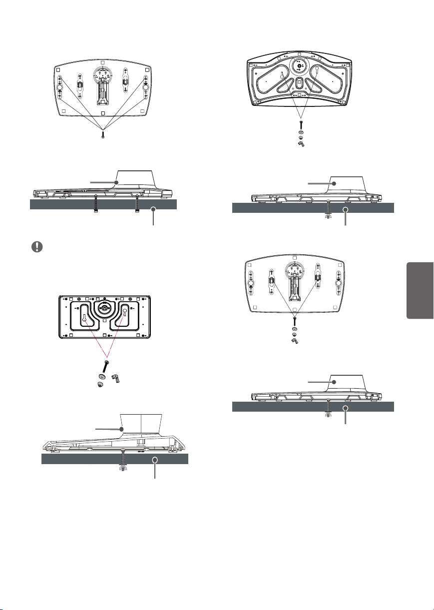
[TYPE 1-3]
[TYPE 2-2]
(Not provided as parts of the product.)
4-Screws
Stand
Desk
NOTE
• Screw: M5 x L (*L: Table depth + 8~10 mm)
ex) Table depth: 15 mm, Screw: M5 x L25
[TYPE 2-1]
2-Screws, 2-Washers, 2-Nuts
(provided as parts of the product.)
Stand
2-Screws, 2-Washers, 2-Nuts
(provided as parts of the product.)
Stand
[TYPE 2-3]
2-Screws, 2-Washers, 2-Nuts
(provided as parts of the product.)
Stand
Desk
ENGLISH
Desk
Desk
9
Page 10
Using the kensington security
system
(Depending upon model)
The Kensington security system connector is
located at the rear of the TV. For more information
of installation and using, refer to the manual
provided with the Kensington security system
or visit http://www.kensington.com. Connect the
Kensington security system cable between the TV
and a table.
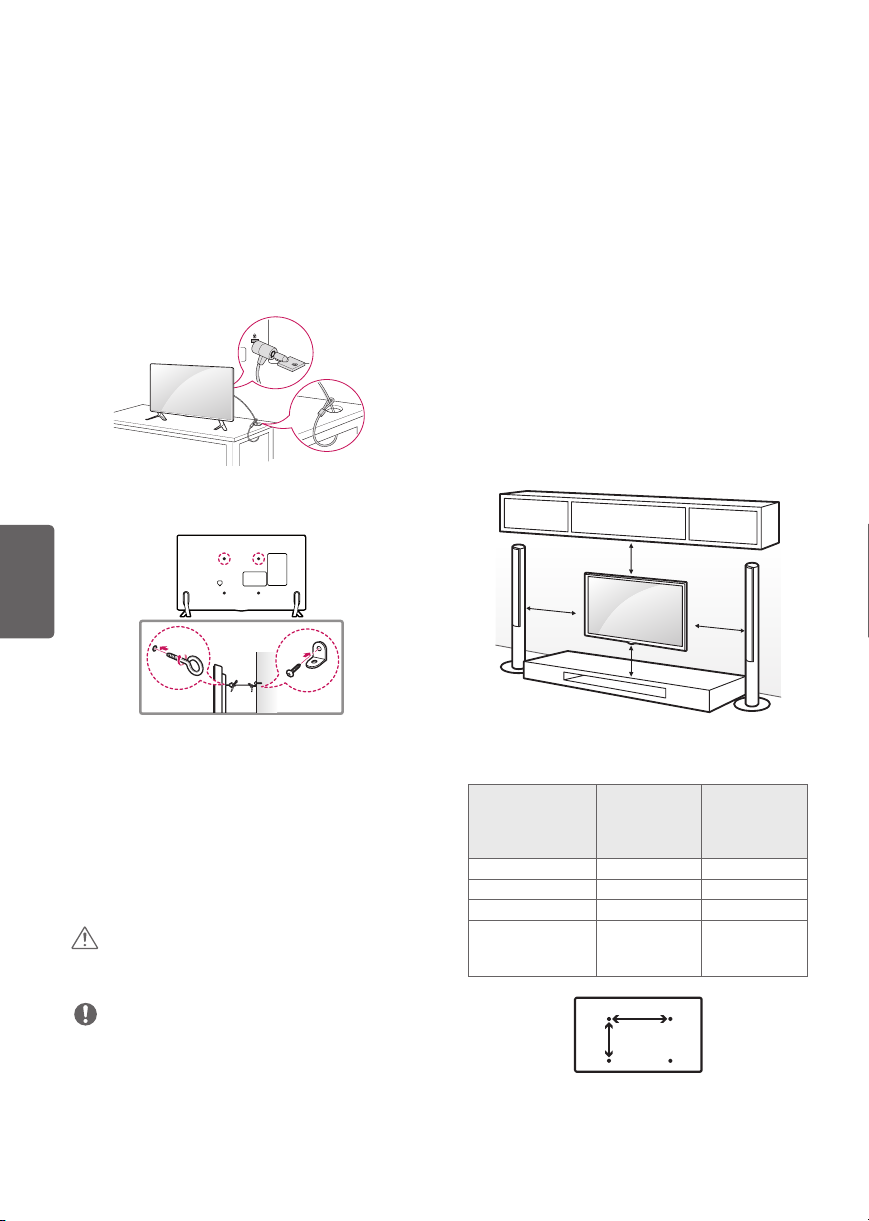
Securing the TV to a Wall (optional)
Mounting on a Wall
An optional wall mount can be used with your
LG Television. Consult with your local dealer for
a wall mount that supports the VESA standard
used by your TV model. Carefully attach the wall
mount bracket at the rear of the TV. Install the wall
mount bracket on a solid wall perpendicular to the
floor. If you are attaching the TV to other building
materials, please contact qualified personnel to
install the wall mount. Detailed instructions will
be included with the wall mount. We recommend
that you use an LG brand wall mount. The LG wall
mount is easy to adjust or to connect the cables.
When you do not use LG’s wall mount bracket,
use a wall mount bracket where the device is
adequately secured to the wall with enough space
to allow connectivity to external devices. If you are
using a non-adjustable mount, attach the mount
to the wall. Attach the cables to the TV first, then
attach the TV to the mount.
ENGLISH
1 Insert and tighten the eye-bolts or TV brackets
and bolts on the back of the TV.
- If there are bolts inserted at the eye-bolts
position, remove the bolts first.
2 Mount the wall brackets with the bolts to the
wall. Match the location of the wall bracket and
the eye-bolts on the rear of the TV.
3 Connect the eye-bolts and wall brackets tightly
with a sturdy rope or cable. Make sure to keep
the rope parallel to the flat surface.
CAUTION
• Make sure that children do not climb on or hang
on the TV.
NOTE
• Use a platform or cabinet that is strong and large
enough to support the TV securely.
• Brackets, bolts, and ropes are optional. You can
obtain additional accessories from your local
dealer.
10
10 cm
(4 inches)
10 cm
10 cm
Make sure to use screws and wall mounts that meet
the VESA standard. Standard dimensions for the
wall mount kits are described in the following table.
32LW300C
Model
VESA (A x B) 200 x 200 300 x 300
Standard screw M6 M6
Number of screws
Wall mount
bracket
(optional)
32/43LW340C
32/43LW340H
43LW540S
4 4
LSW240B
MSW240
10 cm
49/55LW340C
49/55LW340H
49/55LW540S
LSW350B
MSW240
A
B
Page 11

CAUTION
• Remove the stand before installing the TV on a
wall mount by performing the stand attachment
in reverse.
NOTE
• When using the wall mounting bracket, apply
the adhesive protective label to cover the
unused stand openings. This will prevent the
accumulation of dust and dirt. (Use only when
provided with your particular model.)
Provided Item
Adhesive
protective label
• When using the wall mount, it is recommended
that you apply a piece of tape over the stand
holes to prevent dust and bugs from entering
the holes.
(Depending upon model)
NOTE
• If you record a TV program on a DVD recorder or
VCR, make sure to connect the TV signal input
cable to the TV through a DVD recorder or VCR.
For more information about recording, refer to
the manual provided with the connected device.
• The external device connections shown may
differ slightly from illustrations in a manual.
• Connect external devices to the TV regardless
about the order of the TV port. If you connect a
gaming device to the TV, use the cable supplied
with the gaming device.
• Refer to the external equipment’s manual for
operating instructions.
• In PC mode, there may be noise associated
with the resolution, vertical pattern, contrast
or brightness. If noise is present, change the PC
output to another resolution, change the refresh
rate to another rate or adjust the brightness and
contrast on the PICTURE menu until the picture
is clear.
Connecting to an Antenna or Cable
Connect an antenna, cable, or cable box to watch
TV while referring to the following. The illustrations
may differ from the actual items and an RF cable is
optional.
CAUTION
• Make sure not to bend the copper wire of the RF
cable.
ENGLISH
Stand Hole
Connections (Notifications)
You can connect various external devices to the TV.
Supported external devices are: HD receivers, DVD
players, VCRs, audio systems, USB storage devices,
PC, gaming devices, and other external devices. For
more information on external device’s connection,
refer to the manual provided with each device.
Copper wire
• Complete all connections between devices, and
then connect the power cord to the power outlet
to prevent damage to your TV.
NOTE
• Use a signal splitter to use 2 TVs or more.
• DTV Audio Supported Codec: MPEG, Dolby
Digital.
Other Connections
Connect your TV to external devices. For the best
picture and audio quality, connect the external
device and the TV with the HDMI cable.
NOTE
• Use only with the 3 pole 3.5 mm stereo jack.
• Do not connect your headphones or earphones
to the port for connecting an external speaker.
11
Page 12
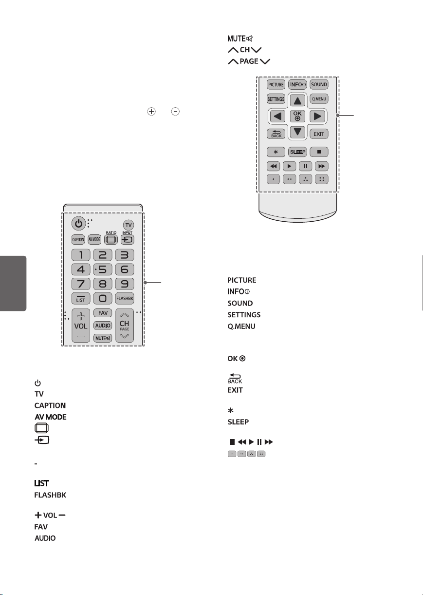
Remote Control
(Depending upon model)
The descriptions in this manual are based on
the buttons on the remote control. Please read
this manual carefully and use the TV correctly. To
install batteries, open the battery cover, replace
batteries (1.5 V AAA) matching the and ends
to the label inside the compartment, and close
the battery cover. Failure to match the correct
polarities of the battery may cause the battery
to burst or leak, resulting in fire, personal injury,
or ambient pollution. To remove the batteries,
perform the installation actions in reverse. This
remote uses infrared light. When in use, it should
be pointed in the direction of the TV’s remote
sensor.
Mutes all sounds.
Scrolls through the saved channels.
Moves to the previous or next screen.
B
ENGLISH
A
(Power) Turns the TV on or off.
Returns to the last TV channel.
Activates or deactivates the subtitles.
Selects an AV mode.
RATIO Resizes an image.
INPUT Changes the input source.
Number button Enters numbers.
(Dash) Inserts a dash between numbers such as
2-1 and 2-2.
Accesses the saved channel list.
channels selected (pressing repeatedly).
12
Alternates between the two last
Adjusts the volume level.
Accesses your favorite channel list.
Digital signal: Changes the audio language.
Analog signal: Changes the MTS sound.
B
A
Changes the picture mode.
Shows information on the current program.
Changes the sound mode.
Accesses the main menu.
Accesses the quick menu.
Navigation button (up / down / left / right)
Scrolls through menus or options.
Selects menus or options and confirms your
input.
Returns to the previous screen.
Clears all on-screen displays and returns to TV
viewing.
Not functional.
Sets the length of time until the TV to turns
off.
, , , , Control buttons for media contents
These access special functions in some
menus.
Page 13
To select Picture Mode
Specifications
SETTINGS PICTURE Picture Mode
Select the picture mode optimized for the viewing
environment or the program.
• Vivid Heightens contrast, brightness, and
sharpness to display vivid images.
• Standard Displays images in standard levels of
contrast, brightness and sharpness.
• APS APS (Auto power saving) mode reduces
power consumption by dimming control.
• Cinema / Sport / Game Displays the optimum
picture for movie, sport, or game.
• Expert Menu for adjusting picture quality that
allows experts and amateurs to enjoy the best TV
viewing. This menu for adjustment is provided
for ISF-certified picture tuning professionals.
(ISF logo can be used only on ISF-certified TVs.)
ISFccc : Imaging Science Foundation Certified
Calibration Control (Depending upon model)
• Depending upon the input signal, the available
range of picture modes may differ.
• Expert mode is for picture tuning professionals to
control and fine-tune using a specific image. For
normal images, the effects may not be drastic.
To Use Energy Saving Feature
(Depending upon model)
SETTINGS PICTURE Energy Saving
Reduces power consumption by adjusting peak
screen brightness.
• Off Turns off the Energy Saving.
• Minimum / Medium / Maximum Applies the
pre-set Energy Saving.
• Screen Off Screen is turned off and only sound is
played. Press any button on the remote control
to turn the screen back on.
Product specifications may be changed without
prior notice due to upgrade of product functions.
Television System
ATSC, NTSC-M, 64 & 256 QAM
Program Coverage
VHF 2-13, UHF 14-69, DTV 2-69, CATV 1-135,
CADTV 1-135
External Antenna Impedance
75
Environment condition
• Operating Temperature
0 °C to 40 °C (32 °F to 104 °F)
• Operating Humidity
Less than 80 %
• Storage Temperature
-20 °C to 60 °C (-4 °F to 140 °F)
• Storage Humidity
Less than 85 %
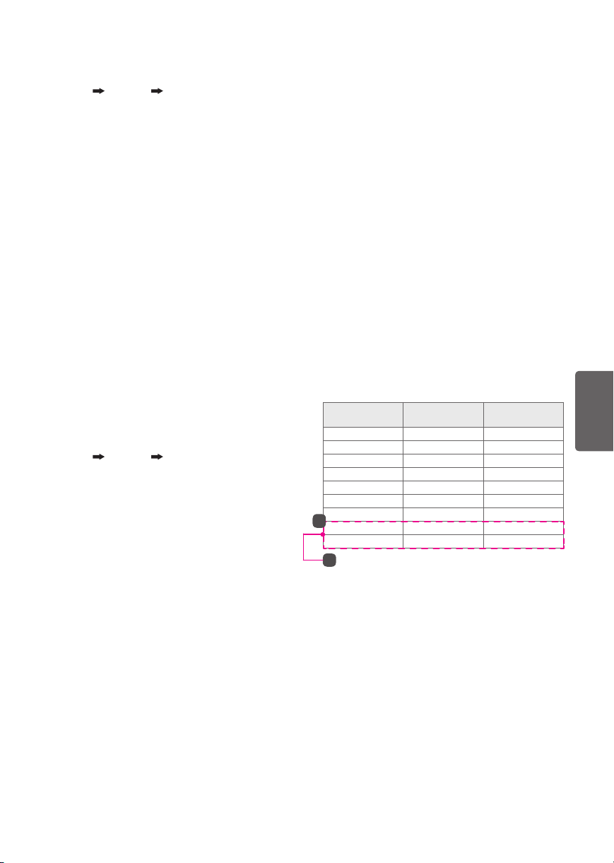
RGB (PC), HDMI (PC) supported mode
(Use HDMI IN 1 for PC mode)
Resolution
640 x 350 31.46 70.09
720 x 400 31.46 70.08
640 x 480 31.46 59.94
800 x 600 37.87 60.31
1024 x 768 48.36 60.00
1152 x 864 54.34 60.05
1360 x 768 47.71 60.01
1
1280 x 1024 63.98 60.02
1920 x 1080 67.50 60.00
1
: Except for 32LW300C, 32LW340C, 32LW340H
Horizontal
Frequency (kHz)
Vertical
Frequency (Hz)
ENGLISH
13
Page 14
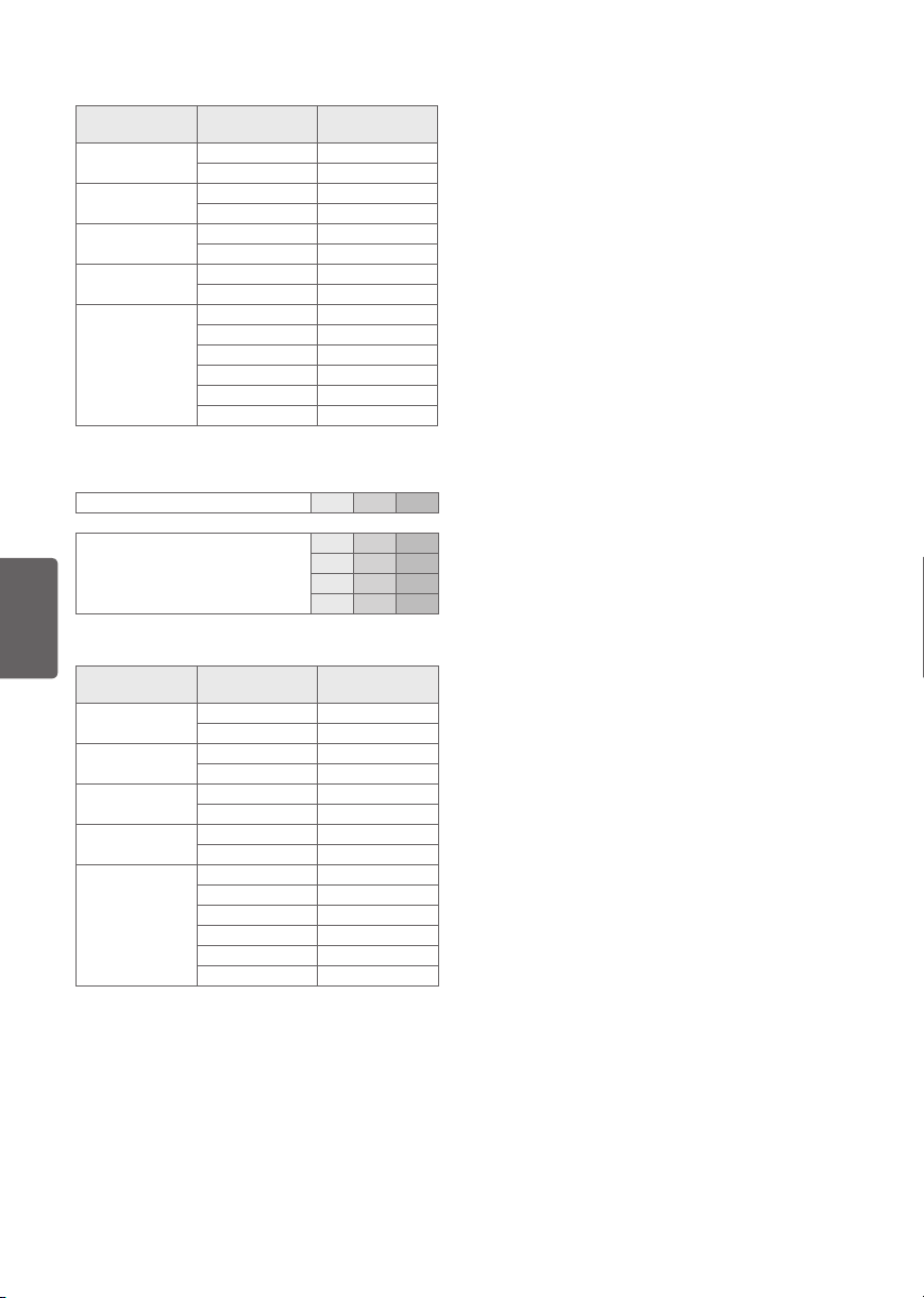
HDMI (DTV) supported mode
Resolution
640 x 480p
720 x 480p
1280 x 720p
1920 x 1080i
1920 x 1080p
Horizontal
Frequency (kHz)
31.46 59.94
31.50 60.00
31.47 59.94
31.50 60.00
44.96 59.94
45.00 60.00
33.72 59.94
33.75 60.00
26.97 23.97
27.00 24.00
33.71 29.97
33.75 30.00
67.43 59.94
67.50 60.00
Component port connecting information
Component ports on the TV Y PBP
ENGLISH
Video output ports on DVD player
Component Supported Mode
Resolution
720 x 480i
720 x 480p
1280 x 720p
1920 x 1080i
1920 x 1080p
Horizontal
Frequency (kHz)
15.73 59.94
15.73 60.00
31.47 59.94
31.50 60.00
44.96 59.94
45.00 60.00
33.72 59.94
33.75 60.00
26.97 23.976
27.00 24.00
33.71 29.97
33.75 30.00
67.432 59.94
67.50 60.00
Vertical
Frequency (Hz)
Y PBP
Y B-Y R-Y
Y Cb Cr
Y Pb Pr
Vertical
Frequency (Hz)
Supported Video Formats
• Maximum: 1,920 x 1,080 @ 30p (only Motion
JPEG 640 x 480 @ 30p)
• .asf, .wmv
[Video] MPEG-2, MPEG-4 Part2, XViD, H.264/AVC,
VC1(WMV3, WVC1), MP4
[Audio] WMA Standard, WMA9(Pro), MP3, AAC,
AC3
• .divx, .avi
[Video] MPEG-2, MPEG-4 Part2, DivX3.11, DivX4,
DivX5, DivX6, XViD, H.264/AVC
[Audio] HE-AAC, LPCM, ADPCM, MPEG-1 Layer I,
MPEG-1 Layer II, Dolby Digital, MPEG-1 Layer III
(MP3), *DTS
• .ts, .trp, .tp, .mts, .m2ts
[Video] H.264/AVC, MPEG-2, AVS, VC1
[Audio] MPEG-1 Layer I, MPEG-1 Layer II, MPEG-1
Layer III (MP3), Dolby Digital, Dolby Digital Plus,
AAC, HE-AAC, *DTS
• .vob
[Video] MPEG-1, MPEG-2
R
R
[Audio] Dolby Digital, MPEG-1 Layer I, MPEG-1
Layer II, DVD-LPCM
• .mp4, .m4v, .mov
[Video] MPEG-2, MPEG-4 Part2, DivX3.11, DivX4,
DivX5, DivX6, XVID, H.264/AVC
[Audio] AAC, MPEG-1 Layer III (MP3), *DTS
• .mkv
[Video] MPEG-2, MPEG-4 Part2, XVID, H.264/AVC
[Audio] HE-AAC, Dolby Digital, MPEG-1 Layer III
(MP3), *DTS, LPCM
• motion JPEG
[Video] MJPEG
[Audio] LPCM, ADPCM
• .mpg, .mpeg, .mpe
[Video] MPEG-1, MPEG-2
[Audio] MPEG-1 Layer I, MPEG-1 Layer II, Dolby
Digital, LPCM
• .dat
[Video] MPEG-1, MPEG-2
[Audio] MP2
• .flv
[Video] Sorenson H.263, H.264/AVC
[Audio] MP3, AAC, HE-AAC
• .3gp, .3gp2
[Video] H.264/AVC, MPEG-4 Part2
[Audio] AAC, AMR(NB/WB)
• *DTS: Depending upon model
14
Page 15

Supported Audio Formats
• File type: mp3
[Bit rate] 32 Kbps - 320 Kbps
[Sample freq.] 16 kHz - 48 kHz
[Support] MPEG-1, MPEG-2, Layer2, Layer3
• File Type: AAC
[Bit rate] Free Format
[Sample freq.] 8 kHz ~ 48 kHz
[Support] ADIF, ADTS
• File Type: M4A
[Bit rate] Free Format
[Sample freq.] 8 kHz ~ 48 kHz
[Support] MPEG-4
• File Type: WMA
[Bit rate] 128 Kbps ~ 320 Kbps
[Sample freq.] 8 kHz ~ 48 kHz
[Support] WMA7, WMA8, WMA9 Standard
• File Type: WMA 10 Pro
[Bit rate] ~ 768 Kbps
[Channel / Sample freq.]
M0:
up to 2 Channel @ 48 kHz (Except LBR mode),
M1: up to 5.1 Channel @ 48 kHz,
M2: up to 5.1 Channel @ 96 kHz
[Support] WMA 10 Pro
• File Type: OGG Vorbis
[Bit rate] Free Format
[Sample freq.] ~ 48 kHz
[Support] OGG Vorbis
Supported Photo Formats
• Category: 2D (jpeg, jpg, jpe)
[Available file type]
SOF0: Baseline,
SOF1: Extend Sequential,
SOF2: Progressive
[Photo size]
Minimum: 64 x 64,
Maximum: Normal Type: 15,360 (W) x 8,640 (H),
• Category: BMP
[Photo size]
Minimum: 64 x 64,
Maximum: 9,600 x 6,400
• Category: PNG
[Available file type]
Interlace, Non-Interlace
[Photo size]
Minimum: 64 x 64,
Maximum: Interlace: 1,200 x 800,
• BMP and PNG format files may be slower to
display than JPEG.
• Non-standard photo/image file may not be
displayed.
Progressive Type: 1,920 (W) x 1,440 (H)
Non-Interlace: 9,600 x 6,400
Open Source Software Notice
Information
To obtain the source code under GPL, LGPL, MPL,
and other open source licenses, that is contained in
this product, please visit http://opensource.lge.com.
In addition to the source code, all referred license
terms, warranty disclaimers and copyright notices
are available for download.
LG Electronics will also provide open source code
to you on CD-ROM for a charge covering the cost
of performing such distribution (such as the cost of
media, shipping, and handling) upon email request
to opensource@lge.com. This offer is valid for three
(3) years from the date on which you purchased
the product.
Updating Firmware
(Depending upon model)
You can update the firmware for the product by
downloading the latest firmware.
1 Download the latest firmware at partner.lge.
com. (Signing up for a membership and log-in
required)
2 Create a folder named “LG_DTV” or “lg_dtv” on a
USB memory device.
3 Move the downloaded file to the folder that you
have created on the USB memory device.
4 Connect the USB memory device to the USB
port on your TV.
5 When a pop-up window appears, start the
update by following the instructions.
ENGLISH
15
Page 16

Troubleshooting
Licenses
The software may be updated for improvement
in performance. The customer is responsible to
ensure the compatibility of their equipment with
any LG Electronics software. If needed, please
consult with LG Electronics and update new
software versions according to the guidance
provided by LG Electronics.
• Cannot control the TV with the remote control.
- Check if anything such as tape has been placed
over the receiver.
- Check if there is any obstacle between the
product and the remote control.
- Replace the batteries with new fresh ones.
• No image display and no sound is produced.
- Check if the product is turned on.
- Check if the power cord is connected to a wall
outlet.
- Check if there is a problem in the wall outlet by
connecting other products.
• The TV turns off suddenly.
- Check the power control settings.
The power supply may be interrupted.
- Check if the Off Time / Sleep Timer feature is
ENGLISH
activated in the TIME settings.
- If there is no signal while the TV is on, the TV
will turn off automatically after 15 minutes of
inactivity.
Supported licenses may differ by model.
For more information about licenses,
visit www.lg.com.
Manufactured under license from Dolby
Laboratories.
Dolby and the double-D symbol are trademarks
of Dolby Laboratories.
The terms HDMI and HDMI High-Definition
Multimedia Interface, and the HDMI logo are
trademarks or registered trademarks of HDMI
Licensing LLC in the United States and other
countries.
This DivX Certified® device has passed rigorous
testing to ensure it plays DivX® video. To play
purchased DivX movies, first register your device
at vod.divx.com. Find your registration code in
the DivX VOD section of your device setup menu.
DivX Certified® to play DivX® video up to HD
1080p, including premium content.
DivX®, DivX Certified® and associated logos are
trademarks of DivX, LLC and are used under
license.
Covered by DivX Patents 7,295,673; 7,515,710;
RE45,052; and others available at
[www.divx.com/patents]
16
Software Download Information
(For LW540S series)
You can download the SuperSign Software and
manual from LG Electronics website.
Visit
www.lgecommercial.com/digital-signage/
support/download/supersign
Software :
Manual : SuperSign W_Lite_Server_vX.X.X_Manual.zip
SuperSign W_Lite_Server_vX.X.X_Setup.zip
SuperSign C_vX.X.X_Setup.zip
SuperSign W_Editor_vX.X.X_Setup.zip
SuperSign W_Player_vX.X.X_Setup.zip
SuperSign C_vX.X.X_Manual.zip
SuperSign W_Editor_vX.X.X_Manual.zip
SuperSign W_Player_vX.X.X_Manual.zip
.
Page 17
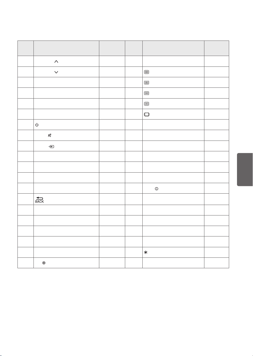
Key CODES
• This feature is not available for all models.
Code
(Hexa)
00 CH PAGE R/C Button 52 SOUND R/C Button
01
CH PAGE
02 VOL + R/C Button 63
03 VOL - R/C Button 71
06 ► R/C Button 72
07 ◄ R/C Button 79
08 (Power) R/C Button 4C - LIST R/C Button
09
MUTE
0B
INPUT
1A FLASHBK R/C Button 8E ►► R/C Button
0F TV R/C Button 8F ◄◄ R/C Button
10 - 19 Number Key 0 - 9 R/C Button 0E SLEEP R/C Button
45 Q.MENU R/C Button AA
28 R/C Button B0 ► R/C Button
30 AV MODE R/C Button B1
Function Note
R/C Button 61
R/C Button 5B EXIT R/C Button
R/C Button 0A AUDIO R/C Button
Code
(Hexa)
RATIO
INFO
ꕗ
Function Note
R/C Button
R/C Button
R/C Button
R/C Button
R/C Button
R/C Button
R/C Button
ENGLISH
39 CAPTION R/C Button BA
40 ▲ R/C Button 1E FAV R/C Button
41 ▼ R/C Button 4D PICTURE R/C Button
43 SETTINGS R/C Button -- R/C Button
44
OK
R/C Button
ꕘ
R/C Button
17
Page 18

EXTERNAL CONTROL DEVICE SETUP
USB IN
(TV)
(PC)
USB IN
(TV)
(PC)
(PC)
RS-232C IN
(CONTROL & SERVICE)
(TV)
(PC
USB IN
(TV)
(PC)
(PC)
RS-232C IN
(CONTROL & SERVICE)
(TV)
(TV)
(PC)
(PC
SERVICE ONLY
1
3
2
• Connect the USB to Serial converter/RS-232C input jack to an external control device (such as a computer or
an A/V control system) to control the product’s functions externally.
Note: The type of control port on the TV can be different between model series.
• Please be advised that not all models support this type of connectivity.
• Cable is not provided.
USB to Serial converter with USB Cable
USB Type
(PC)
• LGTV supports PL2303 chip-based (Vendor ID : 0x0557, Product ID : 0x2008) USB to serial converter which is
not made nor provided by LG.
• It can be purchased from computer stores that carry accessories for IT support professionals.
ENGLISH
RS-232C with RS-232C Cable
USB IN
(TV)
DE9 (D-Sub 9 pin) Type
• You need to purchase the RS-232C (DE9, D-Sub 9 pin female-to-female type) to RS-232C cable required for
the connection between the PC and the TV, which is specified in the manual.
• The connection interface may differ from your TV.
RS-232C IN
(PC)
(CONTROL & SERVICE)
(TV)
Phone jack Type
• You need to purchase the phone-jack to RS-232C cable required for the connection between the PC and the
TV, which is specified in the manual.
• For other models, connect to the USB port.
• The connection interface may differ from your TV.
)
- or
)
18
1
3
2
1
3
2
SERVICE ONLY
RS-232C IN
(CONTROL & SERVICE)
(TV)
(TV)
Page 19

Set ID
For Set ID number, see “Real Data Mapping”.
1 Press SETTINGS to access the main menus.
2 Press the Navigation buttons to scroll to OPTION and press OK.
3 Press the Navigation buttons to scroll to SET ID and press OK.
4 Scroll left or right to select a set ID number and select CLOSE. The adjustment range is 1-99.
5 When you are finished, press EXIT.
Customer Computer
1
5
6
RS-232C
(Serial port)
9
RS-232C Configurations
7-Wire Configurations
(Standard RS-232C cable)
PC TV
RXD 2 3 TXD
TXD 3 2 RXD
GND 5 5 GND
DTR 4 6 DTR
DSR 6 4 DSR
RTS 7 8 RTS
CTS 8 7 CTS
D-Sub 9 D-Sub 9
ENGLISH
3-Wire Configurations
(Not standard)
PC TV
RXD 2 3 TXD
TXD 3 2 RXD
GND 5 5 GND
DTR 4 6 DTR
DSR 6 4 DSR
RTS 7 8 RTS
CTS 8 7 CTS
D-Sub 9 D-Sub 9
19
Page 20

Communication Parameters
Baud rate : 9600 bps (UART)
Data length : 8 bits
Parity : None
Stop bit : 1 bit
Communication code : ASCII code
Use a crossed (reverse) cable.
Command reference list
(Depending upon model)
COMMAND1 COMMAND2
01. Power* k a 00 to 01 14. Bass k s 00 to 64
02. Aspect
Ratio
03. Screen
Mute
04. Volume
Mute
05. Volume
Control
06. Contrast k g 00 to 64
ENGLISH
07. Brightness k h 00 to 64
08. Color/
Colour
09. Tint k j 00 to 64
10. Sharpness k k 00 to 32
11. OSD Select k l 00 to 01
12. Remote
Control Lock
Mode
13. Treble k r 00 to 64
k c (page 22) 15. Balance k t 00 to 64
k d (page 22)
k e 00 to 01 17. Equalizer j v (page 24)
k f 00 to 64
k i 00 to 64 21. Key m c (page 26)
k m 00 to 01
DATA
(Hexadecimal)
16. Color
(Colour)
Temperature
18. Energy
Saving
19. Tune
Command
20. Channel
(Programme)
Add/
Del(Skip)
22. Control
Backlight,
Control Panel
Light
23. Input
select (Main)
24. 3D (Only
3D models)
25. Extended
3D (Only 3D
models)
26. Auto
Configure
COMMAND1 COMMAND2
x u 00 to 64
j q 00 to 05
m a (page 24)
m b 00 to 01
m g 00 to 64
x b (page 26)
x t (page 26)
x v (page 27)
j u (page 27)
DATA
(Hexadecimal)
* Note: During playing or recording media, all commands except Power (ka) and Key (mc) are not executed
and treated as NG. With RS-232C cable, TV can communicate “ka command” in power-on or power-off
status. But with USB-to-Serial converter cable, the command works only if TV is on.
20
Page 21

Transmission / Receiving Protocol
Transmission
[Command1][Command2][ ][Set ID][ ][Data][Cr]
[Command 1] : First command to control the TV. (j, k, m or x)
[Command 2] : Second command to control the TV.
[Set ID] : You can adjust the [Set ID] to choose desired monitor ID number in option menu.
Adjustment range in TV is 1 to 99. If [Set ID] value is selected to ‘0’, every connected set can be
controlled.
* [Set ID] is indicated as decimal (1 to 99) on menu and as Hexadecimal (0x00 to 0x63) on
transmission/receiving protocol.
[DATA] : To transmit command data (hexadecimal). Transmit ‘FF’ data to read status of command.
[Cr] : Carriage Return - ASCII code ‘0x0D’
[ ] : Space – ASCII code ‘0x20’
OK Acknowledgement
[Command2][ ][Set ID][ ][OK][Data][x]
The set transmits ACK (acknowledgement) based on this format when receiving normal data. At this time,
if the data is data read mode, it indicates present status data. If the data is data write mode, it returns the data
of the PC computer.
Error Acknowledgement
[Command2][ ][Set ID][ ][NG][Data][x]
The set transmits ACK (acknowledgement) based on this format when receiving abnormal data from
non-viable functions or communication errors.
Data 00: Illegal Code
Real data mapping (Hexadecimal : Decimal)
• When you enter the [data] in hexadecimal, refer to following conversion table.
• Channel Tune (ma) Command uses two-byte hexadecimal value([data]) to select channel number.
00 : Step 0 32 : Step 50 (Set ID 50) FE : Step 254
01 : Step 1 (Set ID 1) 33 : Step 51 (Set ID 51) FF : Step 255
... ... ...
0A : Step 10 (Set ID 10) 63 : Step 99 (Set ID 99) 01 00 : Step 256
... ... ...
0F : Step 15 (Set ID 15) C7 : Step 199 27 0E : Step 9998
10 : Step 16 (Set ID 16) C8 : Step 200 27 0F : Step 9999
... ... ...
ENGLISH
21
Page 22

• Commands may work differently depending
upon model and signal.
01. Power (Command: k a)
• To control Power *On or Off of the set.
Transmission[k][a][ ][Set ID][ ][Data][Cr]
Data 00 : Power Off
Ack [a][ ][Set ID][ ][OK/NG][Data][x]
• To Show TV is Power On or *Off
Transmission [k][a][ ][Set ID][ ][FF][Cr]
Ack [a][ ][Set ID][ ][OK][Data][x]
- Similarly, if other functions transmit ‘FF’ data
based on this format, Acknowledgement
feedback presents status about each function.
02. Aspect Ratio (Command: k c)
(Main Picture Size)
• To adjust the screen format. (Main picture
format)
You can also adjust the screen format using the
Aspect Ratio in the Q.MENU or PICTURE menu.
ENGLISH
Transmission [k][c][ ][Set ID][ ][Data][Cr]
Data 01 : Normal screen (4:3)
02 : Wide screen(16:9)
04 : Zoom
05 : Zoom 2
(Latin America except
Colombia Only)
06 : Set by Program/
Original
Ack [c][ ][Set ID][ ][OK/NG][Data][x]
• Using the PC input, you select either 16:9 or 4:3
screen aspect ratio.
• In DTV/HDMI/Component mode (high-
definition), Just Scan is available.
• Full wide mode may work differently based on
model and is supported for DTV fully, and ATV,
AV partially.
03. Screen Mute (Command: k d)
• To select screen mute on/off.
Transmission [k][d][ ][Set ID][ ][Data][Cr]
01 : *Power On
07 : 14:9
(Europe, Colombia,
Mid-East, Asia except
South Korea and
Japan)
09 : * Just Scan
0B : Full Wide
(Europe, Colombia,
Mid-East, Asia except
South Korea and
Japan)
10 to 1F : Cinema
Zoom 1
to 16
Data 00 : Screen mute off (Picture on)
Video mute off
01 : Screen mute on (Picture off)
10 : Video mute on
Ack [d][ ][Set ID][ ][OK/NG][Data][x]
- In case of video mute on only, TV will display
On Screen Display(OSD). But, in case of Screen
mute on, TV will not display OSD.
04. Volume Mute (Command: k e)
• To control volume mute on/off.
You can also adjust mute using the MUTE button
on remote control.
Transmission [k][e][ ][Set ID][ ][Data][Cr]
Data 00 : Volume mute on (Volume off)
01 : Volume mute off (Volume on)
Ack [e][ ][Set ID][ ][OK/NG][Data][x]
05. Volume Control (Command: k f)
• To adjust volume.
You can also adjust volume with the volume
buttons on remote control.
Transmission [k][f][ ][Set ID][ ][Data][Cr]
Data Min : 00 to Max : 64
Ack [f][ ][Set ID][ ][OK/NG][Data][x]
06. Contrast (Command: k g)
• To adjust screen contrast.
You can also adjust contrast in the PICTURE
menu.
Transmission [k][g][ ][Set ID][ ][Data][Cr]
Data Min : 00 to Max : 64
Ack [g][ ][Set ID][ ][OK/NG][Data][x]
07. Brightness (Command: k h)
• To adjust screen brightness.
You can also adjust brightness in the PICTURE
menu.
Transmission [k][h][ ][Set ID][ ][Data][Cr]
Data Min : 00 to Max : 64
Ack [h][ ][Set ID][ ][OK/NG][Data][x]
22
Page 23

08. Color/Colour (Command: k i)
• To adjust the screen Color(Colour).
You can also adjust colour in the PICTURE menu.
Transmission [k][i][ ][Set ID][ ][Data][Cr]
Data Min : 00 to Max : 64
Ack [i][ ][Set ID][ ][OK/NG][Data][x]
09. Tint (Command: k j)
• To adjust the screen tint.
You can also adjust tint in the PICTURE menu.
Transmission [k][j][ ][Set ID][ ][Data][Cr]
Data Red : 00 to Green : 64
Ack [j][ ][Set ID][ ][OK/NG][Data][x]
10. Sharpness (Command: k k)
• To adjust the screen sharpness.
You can also adjust sharpness in the PICTURE
menu.
Transmission [k][k][ ][Set ID][ ][Data][Cr]
Data Min : 00 to Max : 32
Ack [k][ ][Set ID][ ][OK/NG][Data][x]
11. OSD Select (Command: k l)
• To select OSD (On Screen Display) on/off when
controlling remotely.
Transmission [k][l][ ][Set ID][ ][Data][Cr]
Data 00 : OSD off 01 : OSD on
Ack [l][ ][Set ID][ ][OK/NG][Data][x]
12. Remote control lock mode (Command: k m)
• To lock the front panel controls on the monitor
and remote control.
Transmission [k][m][ ][Set ID][ ][Data][Cr]
13. Treble (Command: k r)
• To adjust treble.
You can also adjust in the AUDIO menu.
Transmission [k][r][ ][Set ID][ ][Data][Cr]
Data Min : 00 to Max : 64
Ack [r][ ][Set ID][ ][OK/NG][Data][x]
* (Depending upon model)
14. Bass (Command: k s)
• To adjust Bass.
You can also adjust in the AUDIO menu.
Transmission [k][s][ ][Set ID][ ][Data][Cr]
Data Min : 00 to Max : 64
Ack [s][ ][Set ID][ ][OK/NG][Data][x]
* (Depending upon model)
15. Balance (Command: k t)
• To adjust balance.
You can also adjust balance in the AUDIO menu.
Transmission [k][t][ ][Set ID][ ][Data][Cr]
Data Min : 00 to Max : 64
Ack [t][ ][Set ID][ ][OK/NG][Data][x]
16. Color(Colour) Temperature (Command: x u)
• To adjust colour temperature. You can also
adjust Color(Colour) Temperature in the
PICTURE menu.
Transmission [x][u][ ][Set ID][ ][Data][Cr]
Data Min : 00 to Max : 64
Ack [u][ ][Set ID][ ][OK/NG][Data][x]
ENGLISH
Data 00 : Lock off 01 : Lock on
Ack [m][ ][Set ID][ ][OK/NG][Data][x]
- If you are not using the remote control, use this
mode. When main power is off & on (plug-off
and plug-in, after 20 - 30 seconds), external
control lock is released.
- In the standby mode (DC off by off timer or ‘ka’,
‘mc’ command), and if key lock is on, TV will not
turn on by power on key of IR & Local Key.
23
Page 24

17. Equalizer (Command : j v)
• Adjust EQ of the set.
Transmission [j][v][ ][Set ID][ ][Data][Cr]
MSB
0 0 0 0 0 0 0 0
Frequency
7 6 5 Frequency 4 3 2 1 0 Step
0 0 0
0 0 1
0 1 0
0 1 1
1 0 0
1st Band
2nd Band
3rd Band
4th Band
5th Band
Data
0 0 0 0 0
0 0 0 0 1
... ... ... ... ...
1 0 0 1 1
1 0 1 0 0
Acknowledgement [v][ ][Set ID][ ][OK/NG][Data][x]
- It depends upon model, and can adjust when
sound mode is EQ adjustable value.
ENGLISH
18. Energy Saving (Command: j q)
• To reduce the power consumption of the TV. You
can also adjust Energy Saving in PICTURE menu.
Transmission [j][q][ ][Set ID][ ][Data][Cr]
Data
00 : Off
01 : Minimum
02 : Medium
03 : Maximum
04 : Auto (For LCD TV / LED TV) /
Intelligent sensor (For PDP TV)
05 : Screen off
(Depending upon model)
Ack [q][ ][Set ID][ ][OK/NG][Data][x]
LSB
0(decimal)
1(decimal)
...
19(decimal)
20(decimal)
19. Tune Command (Command: m a)
- This command may work differently depending
upon model and signal.
• For Europe, Mid-East, Colombia, Asia except
South Korea and Japan Model
• Select channel to following physical number.
Transmission [m][a][ ][Set ID][ ][Data 00][ ]
[Data 01][ ][Data 02][Cr]
- Analog Antenna/Cable
[Data 00][Data 01] Channel Data
Data 00 : High byte channel data
Data 01 : Low byte channel data
- 00 00 ~ 00 C7 (Decimal : 0 ~ 199)
Data 02 : Input Source (Analog)
- 00 : Antenna TV (ATV)
- 80 : Cable TV (CATV)
- Digital Antenna/Cable/Satellite
[Data 00][Data 01]: Channel Data
Data 00 : High Channel data
Data 01 : Low Channel data
- 00 00 ~ 27 0F (Decimal: 0 ~ 9999)
Data 02 : Input Source (Digital)
- 10 : Antenna TV (DTV)
- 20 : Antenna Radio (Radio)
- 40 : Satellite TV (SDTV)
- 50 : Satellite Radio (S-Radio)
- 90 : Cable TV (CADTV)
- a0 : Cable Radio (CA-Radio)
- Tune Command Examples:
1. Tune to the Analog antenna (PAL) Channel 10.
Set ID = All = 00
Data 00 & 01 = Channel Data is 10 = 00 0a
Data 02 = Analog Antenna TV = 00
Result = ma 00 00 0a 00
2. Tune to the digital antenna (DVB-T) Channel 01.
Set ID = All = 00
Data 00 & 01 = Channel Data is 1 = 00 01
Data 02 = Digital Antenna TV = 10
Result = ma 00 00 01 10
24
Page 25

3. Tune to the satellite (DVB-S) Channel 1000.
Set ID = All = 00
Data 00 & 01 = Channel Data is 1000 = 03 E8
Data 02 = Digital Satellite TV = 40
Result = ma 00 03 E8 40
Ack [a][ ][Set ID][ ][OK][Data 00][Data 01]
[Data 02][x][a][ ][Set ID][ ][NG][Data 00][x]
• For South Korea, North/Latin America except
Colombia Model
• To tune channel to following physical/major/
minor number.
Transmission [m][a][ ][0][ ][Data00][ ][Data01]
[ ][Data02][ ][Data03][ ][Data04][ ][Data05][Cr]
Digital channels have a Physical, Major, and Minor
channel number. The Physical number is the actual
digital channel number, the Major is the number
that the channel should be mapped to, and the
Minor is the sub-channel. Since the ATSC tuner
automatically maps the channel from the Major /
Minor number, the Physical number is not required
when sending a command in Digital.
- Analog Antenna/Cable
Data 00 : Physical Channel Number
- Antenna (ATV) : 02~45 (Decimal: 2 ~ 69)
- Cable (CATV) : 01, 0E~7D (Decimal : 1, 14~125)
[Data 01 ~ 04]: Major/Minor Channel Number
Data 01 & 02: xx (Don’t care)
Data 03 & 04: xx (Don’t care)
Data 05: Input Source (Analog)
- 00 : Antenna TV (ATV)
- 01 : Cable TV (CATV)
- Digital Antenna/Cable
Data 00 : xx (Don’t care)
[Data 01][Data 02]: Major Channel Number
Data 01 : High byte Channel Data
Data 02 : Low byte Channel Data
- 00 01 ~ 27 0F (Decimal: 1 ~ 9999)
[Data 03][Data 04]: Minor Channel Number
Data 03 : High byte Channel Data
Data 04 : Low byte Channel Data
Data 05 : Input Source (Digital)
- 02 : Antenna TV (DTV) – Use Physical Channel
Number
- 06 : Cable TV (CADTV) – Use Physical Channel
Number
- 22 : Antenna TV (DTV) – Don’t Use Physical
Channel Number
- 26 : Cable TV (CADTV) - Don’t Use Physical
Channel Number
- 46 : Cable TV (CADTV) – Use Physical/Major
Channel Number Only (One Part Channel)
- 66 : Cable TV (CADTV) – Use Major Channel
Number Only (One Part Channel)
Two bytes are available for each major and minor
channel data, but usually the low byte is used
alone (high byte is 0).
- Tune Command Examples:
1. Tune to the Analog cable (NTSC) channel 35.
Set ID = All = 00
Data 00 = Channel Data is 35 = 23
Data 01 & 02 = No Major = 00 00
Data 03 & 04 = No Minor = 00 00
Data 05 = Analog Cable TV = 01
Total = ma 00 23 00 00 00 00 01
2. Tune to the digital antenna (ATSC) channel 30-3.
Set ID = All = 00
Data 00 = Don’t know Physical = 00
Data 01 & 02 = Major is 30 = 00 1E
Data 03 & 04 = Minor is 3 = 00 03
Data 05 = Digital Antenna TV = 22
Total = ma 00 00 00 1E 00 03 22
Ack [a][ ][Set ID][ ][OK][Data 00][Data 01]
[Data 02][Data 03][Data 04][Data 05]
[x][a][ ][Set ID][ ][NG][Data 00][x]
• For Japan Model
• To tune channel to following physical/major/
minor number.
Transmission [m][a][ ][0][ ][Data00][ ][Data01]
[ ][Data02][ ][Data03][ ][Data04][ ][Data05][Cr]
- Digital Antenna/Satellite
Data 00: xx (Don’t care)
[Data 01][Data 02]: Major Channel Number
Data 01: High byte Channel Data
Data 02: Low byte Channel Data
- 00 01 ~ 27 0F (Decimal: 1 ~ 9999)
ENGLISH
25
Page 26

[Data 03][Data 04]: Minor/Branch Channel Number
Data 03: High byte Channel Data
Data 04: Low byte Channel Data
Data 05 : Input Source (Digital/Satellite for Japan)
- 02 : Antenna TV (DTV)
- 07 : BS (Broadcasting Satellite)
- 08 : CS1 (Communication Satellite 1)
- 09 : CS2 (Communication Satellite 2)
- Tune Command Examples:
1.
Tune to the digital antenna (ISDB-T ) channel 17-1.
Set ID = All = 00
Data 00 = Don’t know Physical = 00
Data 01 & 02 = Major is 17 = 00 11
Data 03 & 04 = Minor/Branch is 1 = 00 01
Data 05 = Digital Antenna TV = 02
Total = ma 00 00 00 11 00 01 02
2. Tune to the BS (ISDB-BS) channel 30.
Set ID = All = 00
Data 00 = Don’t know Physical = 00
Data 01 & 02 = Major is 30 = 00 1E
ENGLISH
Data 03 & 04 = Don’t Care = 00 00
Data 05 = Digital BS TV = 07
Total = ma 00 00 00 1E 00 00 07
- This feature is varied based on the model.
Ack [a][ ][Set ID][ ][OK][Data 00][Data 01]
[Data 02][Data 03][Data 04][Data 05]
[x][a][ ][Set ID][ ][NG][Data 00][x]
20. Channel(Programme) Add/Del(Skip)
(Command: m b)
• To skip current channel(programme) for next
time.
Transmission [m][b][ ][Set ID][ ][Data][Cr]
Data 00 : Del(ATSC,ISDB)/Skip(DVB) 01 : Add
Ack [b][ ][Set ID][ ][OK/NG][Data][x]
- Set the saved channel status to del(ATSC, ISDB)/
skip(DVB) or add.
21. Key (Command: m c)
• To send IR remote key code.
Transmission [m][c][ ][Set ID][ ][Data][Cr]
Data Key code - page 17.
Ack [c][ ][Set ID][ ][OK/NG][Data][x]
(Don’t care in Satellite)
22. Control Backlight, Control Panel Light
(Command: m g)
• For LCD TV / LED TV
• To control the backlight.
Transmission [m][g][ ][Set ID][ ][Data][Cr]
Data Min : 00 to Max : 64
Ack [g][ ][Set ID][ ][OK/NG][Data][x]
• For Plasma TV
• To control the panel light.
Transmission [m][g][ ][Set ID][ ][Data][Cr]
Data Min : 00 to Max : 64
Ack [g][ ][Set ID][ ][OK/NG][Data][x]
23. Input select (Command: x b)
(Main Picture Input)
• To select input source for main picture.
Transmission [x][b][ ][Set ID][ ][Data][Cr]
Data
00 : DTV
02 : Satellite DTV
ISDB-BS (Japan)
03 : ISDB-CS1 (Japan)
04 : ISDB-CS2 (Japan)
11 : CATV
20 : AV or AV1 21 : AV2
40 : Component1
60 : RGB
90 : HDMI1
92 : HDMI3
Ack [b][ ][Set ID][ ][OK/NG][Data][x]
- This function depends on model and signal.
24. 3D(Command: x t) (only 3D models)
(Depending upon model)
• To change 3D mode for TV.
Transmission [x][t][ ][Set ID][ ][Data 00][ ]
[Data 01] [ ][Data 02][ ][Data 03][Cr]
(Depending upon model)
Data Structure
[Data 00] 00 : 3D On
01 : 3D Off
02 : 3D to 2D
03 : 2D to 3D
01 : CADTV
10 : ATV
41 : Component2
91 : HDMI2
93 : HDMI4
26
Page 27

[Data 01] 00 : Top and Bottom
01 : Side by Side
02 : Check Board
03 : Frame Sequential
04 : Column interleaving
05 : Row interleaving
[Data 02] 00 : Right to Left
01 : Left to Right
[Data 03] 3D Effect(3D Depth): Min : 00 - Max : 14
(*transmit by Hexadecimal code)
- If [Data 00] is 00 (3D On), [Data 03] has no
meaning.
- If [Data 00] is 01 (3D off) or 02 (3D to 2D), [Data
01], [Data 02] and [Data 03] have no meaning.
- If [Data 00] is 03 (2D to 3D), [Data 01] and
[Data 02] have no meaning.
- If [Data 00] is 00 (3D On) or03 (2D to 3D), [Data
03]works when 3D Mode (Genre) is manual
only.
- All 3D pattern options ([Data 01]) may not be
available according to broadcasting/video
signal.
[Data 00] [Data 01] [Data 02] [Data 03]
00 O O O
01 X X X
02 X X X
03 X O O
X : don’t care
Ack [t][ ][Set ID][ ][OK][Data00][Data01][Data02]
[Data03][x][t][ ][Set ID][ ][NG][Data00][x]
25. Extended 3D(Command: x v) (only 3D models)
(Depending upon model)
• To change 3D option for TV.
Transmission [x][v][ ][Set ID][ ][Data 00][ ]
[Data 01][Cr]
[Data 00] 3D option
00 : 3D Picture Correction
01 : 3D Depth (3D Mode is Manual Only)
02 : 3D Viewpoint
06 : 3D Color Correction
07 : 3D Sound Zooming
08 : Normal Image View
09 : 3D Mode (Genre)
[Data 01] It has own range for each 3D option
1) When [Data 00] is 00
2) When [Data 00] is 01, 02
Data Min: 0 - Max: 14 (*transmit by
Data value range(0 - 20) converts Viewpoint range
(-10 - +10) automatically (Depending upon
model)
3) When [Data 00] is 06, 07
4) When [Data 00] is 08
01 : Change 3D video to 2D video,
5) When [Data 00] is 09
00 : Standard
02 : Cinema
04 : Manual
26. Auto Configure (Command: j u)
• To adjust picture position and minimize image
Data 01 : To set
determined by [Data 00].
00 : Right to Left
01 : Left to Right
Hexadecimal code)
- This option works when 3D Mode (Genre) is
manual only.
00 : Off
01 : On
00 : Revert to 3D video from 3D-to-2D
converted 2D video
except 2D-to-3D video
- If conversion condition doesn’t meet, command
is treated as NG.
01 : Sport
03 : Extreme
05 : Auto
Ack [v][ ][Set ID][ ][OK][Data00][Data01][x]
[v][ ][Set ID][ ][NG][Data00][x]
(Depending upon model)
shaking automatically. It works only in RGB (PC)
mode.
Transmission [j][u][ ][Set ID][ ][Data][Cr]
Ack [u][ ][Set ID][ ][OK/NG][Data][x]
ENGLISH
27
Page 28

Regulatory
FCC NOTICE
(For USA)
This equipment has been tested and found to
comply with the limits for a Class B digital device,
pursuant to Part 15 of the FCC Rules. These limits
are designed to provide reasonable protection
against harmful interference in a residential
installation. This equipment generates, uses
and can radiate radio frequency energy and, if
not installed and used in accordance with the
instructions, may cause harmful interference
to radio communications. However, there is no
guarantee that interference will not occur in a
particular installation. If this equipment does
cause harmful interference to radio or television
reception, which can be determined by turning
the equipment off and on, the user is encouraged
to try to correct the interference by one or more of
the following measures:
- Reorient or relocate the receiving antenna.
- Increase the separation between the
ENGLISH
equipment and the receiver.
- Connect the equipment to an outlet on a circuit
different from that to which the receiver is
connected.
- Consult the dealer or an experienced radio/TV
technician for help.
This device complies with part 15 of the FCC
Rules. Operation is subject to the following two
conditions: (1) this device may not cause harmful
interference and (2) this device must accept any
interference received, including interference that
may cause undesired operation of the device. Any
changes or modifications in construction of this
device which are not expressly approved by the
party responsible for compliance could void the
user’s authority to operate the equipment.
FCC RF Radiation Exposure Statement
[For having wireless function (WLAN, Bluetooth,...)]
This equipment complies with FCC radiation
exposure limits set forth for an uncontrolled
environment. This transmitter must not be
colocated or operating in conjunction with any
other antenna or transmitter. This equipment
should be installed and operated with minimum
distance 20 cm (7.8 inches) between the radiator
and your body. Users must follow the specific
operating instructions for satisfying RF exposure
compliance.
Industry Canada Statement
(For Canada)
[For having wireless function (WLAN, Bluetooth,...)]
This device complies with Industry Canada’s
licence-exempt RSSs. Operation is subject to the
following two conditions:
1. This device may not cause interference; and
2. This device must accept any interference,
including interference that may cause undesired
operation of the device.
IC Radiation Exposure Statement
(For Canada)
[For having wireless function (WLAN, Bluetooth,...)]
This equipment complies with IC radiation
exposure limits set forth for an uncontrolled
environment. This equipment should be installed
and operated with minimum distance 20 cm (7.8
inches) between the antenna & your body.
NOTE : THE MANUFACTURER IS NOT RESPONSIBLE
FOR ANY RADIO OR TV INTERFERENCE CAUSED
BY UNAUTHORIZED MODIFICATIONS TO THIS
EQUIPMENT. SUCH MODIFICATIONS COULD
VOID THE USER’S AUTHORITY TO OPERATE THE
EQUIPMENT.
FCC Radio Frequency Interference
Requirements (for UNII devices)
High power radars are allocated as primary users
of the 5.25 to 5.35 GHz and 5.65 to 5.85 GHz bands.
These radar stations can cause interference with
and/or damage this device. This device cannot be
co-located with any other transmitter.
28
Page 29

WARNING
(For Canada)
[For product having the wireless function using 5
GHz frequency bands]
• The device for operation in the band 5150–5250
MHz is only for indoor use to reduce the
potential for harmful interference to co-channel
mobile satellite systems;
• For devices with detachable antenna(s), the
maximum antenna gain permitted for devices in
the bands 5250-5350 MHz and 5470-5725 MHz
shall be such that the equipment still complies
with the e.i.r.p. limit;
• For devices with detachable antenna(s), the
maximum antenna gain permitted for devices in
the band 5725-5850 MHz shall be such that the
equipment still complies with the e.i.r.p. limits
specified for point-to-point and non-point-topoint operation as appropriate; and
• The worst-case tilt angle(s) necessary to remain
compliant with the e.i.r.p. elevation mask
requirement set forth in Section 6.2.2(3) shall be
clearly indicated.(devices operating in the band
5250-5350 MHz with a maximum e.i.r.p. greater
than 200 mW)
• High-power radars are allocated as primary users
(i.e. priority users) of the bands 5250–5350 MHz
and 5650–5850 MHz and that these radars could
cause interference and/or damage to LE-LAN
devices.
NOTE TO CABLE/TV INSTALLER
(For USA and Canada)
This reminder is provided to call the CATV system
installer’s attention to Article 820-40 of the
National Electric Code (U.S.A.). The code provides
guidelines for proper grounding and, in particular,
specifies that the cable ground shall be connected
to the grounding system of the building, as close
to the point of the cable entry as practical.
WARNING!
Never place a television set in an unstable
location. A television set may fall, causing serious
personal injury or death. Many injuries, particularly
to children, can be avoided by taking simple
precautions such as:
• Using cabinets or stands recommended by the
manufacturer of the television set.
• Only using furniture that can safely support the
television set.
• Ensuring the television set is not overhanging
the edge of the supporting furniture.
• Not placing the television set on tall furniture
(for example, cupboards or bookcases) without
anchoring both the furniture and the television
set to a suitable support.
• Not placing the television set on cloth or other
materials that may be located between the
television set and supporting furniture.
• Educating children about the dangers of
climbing on furniture to reach the television set
or its controls.
If your existing television set is being retained
and relocated, the same considerations as above
should be applied.
Symbols
Refers to alternating current(AC).
Refers to direct current(DC).
Refers to class II equipment.
Refers to stand-by.
Refers to “ON” (power).
Refers to dangerous voltage.
ENGLISH
29
Page 30

Page 31

CHILD SAFETY:
PROPER TELEVISION PLACEMENT MATTERS
THE CONSUMER ELECTRONICS INDUSTRY CARES
• Manufacturers, retailers and the rest of the consumer electronics industry are committed to
making home entertainment safe and enjoyable.
• As you enjoy your television, please note that all televisions – new and old- must be supported on
proper stands or installed according to the manufacturer’s recommendations. Televisions that
are inappropriately situated on dressers, bookcases, shelves, desks, speakers, chests, carts, etc.,
may fall over, resulting in injury.
TUNE IN TO SAFETY
• A LWAYS follow the manufacturer ’s recommendations for the safe installation of your television.
• A LWAYS read and follow all instructions for proper use of your television.
• NEVER allow children to climb on or play on the television or the furniture on which the television
is placed.
• NEVER place the television on furniture that can easily be used as steps, such as a chest of
drawers.
• A LWAYS install the television where it cannot be pushed, pulled over or knocked down.
• A LWAYS route cords and cables connected to the television so that they cannot be tripped
over, pulled or grabbed.
WALL OR CEILING MOUNT YOUR TELEVISION
• A LWAYS contact your retailer about professional installation if you have any doubts about your
ability to safely mount your television.
• A LWAYS use a mount that has been recommended by the television manufacturer and has a
safety certication by an independent laboratory (such as UL, CSA, ETL).
• A LWAYS follow all instructions supplied by the television and mount manufacturers.
• A LWAYS make sure that the wall or ceiling where you are mounting the television is appropriate.
Some mounts are not designed to be mounted to walls and ceilings with steel studs or cinder
block construction. If you are unsure, contact a professional installer.
• Televisions can be heavy. A minimum of two people is required for a wall or ceiling mount
installation.
MOVING AN OLDER TELEVISION TO A NEW PLACE IN
YOUR HOME
• Many new television buyers move their older CRT televisions into a secondary room after the
purchase of a at-panel television. Special care should be made in the placement of older CRT
televisions.
• A LWAYS place your older CRT television on furniture that is sturdy and appropriate for its size
and weight.
• NEVER place your older CRT television on a dresser where children may be tempted to use the
drawers to climb.
• A LWAYS make sure your older CRT television does not hang over the edge of your furniture.
CE.org/safety
Page 32

Declaration of Conformity
Trade Name: LG
Model: 32LW300C-UA, 32LW340C-UA,
43LW340C-UA, 49LW340C-UA,
55LW340C-UA, 32LW340H-UA,
43LW340H-UA, 49LW340H-UA,
55LW340H-UA, 43LW540S-UA,
49LW540S-UA, 55LW540S-UA,
32LW340H-UD, 43LW340H-UD,
49LW340H-UD, 55LW340H-UD.
Responsible Party: LG Electronics Inc.
Address: 1000 Sylvan Ave. Englewood Cliffs NJ
07632 U.S.A
TEL: 201-266-2534
The model and serial numbers of the TV are located
on the back and on one side of the TV. Record them
below should you ever need service.
MODEL
SERIAL
LG Customer Information Center
For inquires or comments, visit www.lg.com or call;
1-888-865-3026
1-888-542-2623
USA, Commercial User
CANADA
Page 33

OWNER’S MANUAL
EXTERNAL CONTROL
DEVICE SETUP
Please read this manual carefully before operating the set and retain it for
future reference.
www.lg.com
Page 34

KEY CODES
2
2
ENGLISH
ENG
KEY CODES
• This feature is not available for all models.
Code
(Hexa)
00 CH +, PR + R/C Button 53 List R/C Button
01 CH -, PR - R/C Button 5B Exit R/C Button
02 Volume + R/C Button 60 PIP(AD) R/C Button
03 Volume - R/C Button 61 Blue R/C Button
06 > (Arrow Key / Right Key) R/C Button 63 Yellow R/C Button
07 < (Arrow Key / Left Key) R/C Button 71 Green R/C Button
08 Power R/C Button 72 Red R/C Button
09 Mute R/C Button 79 Ratio / Aspect Ratio R/C Button
0B Input R/C Button 91 AD (Audio Description) R/C Button
0E SLEEP R/C Button 9E LIVE MENU R/C Button
0F TV, TV/RAD R/C Button 7A User Guide R/C Button
10 - 19 * Number Key 0 - 9 R/C Button 7C Smart / Home R/C Button
1A Q.View / Flashback R/C Button 7E SIMPLINK R/C Button
Function Note
Code
(Hexa)
Function Note
1E FAV (Favorite Channel) R/C Button 8E ►►(Forward) R/C Button
20 Text (Teletext) R/C Button 8F ◄◄(Rewind) R/C Button
21 T. Opt (Teletext Option) R/C Button AA Info R/C Button
28 Return (BACK) R/C Button AB Program Guide R/C Button
30 AV (Audio / Video) Mode R/C Button B0 ►(Play) R/C Button
39 Caption/Subtitle R/C Button B1 ꕗ (Stop / File List) R/C Button
40 Λ
41
42 My Apps R/C Button BB Soccer R/C Button
43 Menu / Settings R/C Button BD ꔄ (REC) R/C Button
44 OK / Enter R/C Button DC 3D R/C Button
45 Q.Menu R/C Button 99 AutoConfig R/C Button
4C List, - (ATSC Only) R/C Button 9F App / * R/C Button
4D PICTURE R/C Button 9B TV / PC R/C Button
52 SOUND R/C Button
* Key code 4C (0x4C) is available on ATSC/ISDB models which use major/minor channel.
(For South Korea, Japan, North America, Latin America except Colombia models)
(Arrow Key / Cursor Up)
V (Arrow Key / Cursor
Down)
R/C Button B5 RECENT R/C Button
R/C Button BA
ꕘ (Freeze / Slow Play /
Pause)
R/C Button
Page 35

EXTERNAL CONTROL DEVICE SETUP
(PC
USB IN
(TV)
(PC
(PC)
3
3
EXTERNAL CONTROL DEVICE SETUP
• Image shown may differ from your TV.
Connect the USB to Serial converter/RS-232C input jack to an external control device (such as a computer
or an A/V control system) to control the product’s functions externally.
Note: The type of control port on the TV can be different between model series.
* Please be advised that not all models support this type of connectivity.
* Cable is not provided.
USB to Serial converter with USB Cable
USB Type
)
• LGTV supports PL2303 chip-based (Vendor ID : 0x0557, Product ID : 0x2008) USB to serial converter
which is not made nor provided by LG.
• It can be purchased from computer stores that carry accessories for IT support professionals.
USB IN
RS-232C With RS232C Cable
DE9 (D-Sub 9pin) Type
• You need to purchase the RS-232C (DE9, D-Sub 9pin female-to-female type) to RS-232C cable required
for the connection between the PC and the TV, which is specified in the manual.
(TV)
ENGENGLISH
)
The connection interface may differ from your TV.
RS-232C IN
(CONTROL & SERVICE)
(TV)
Page 36

EXTERNAL CONTROL DEVICE SETUP
USB IN
(TV)
(PC)
(PC)
RS-232C IN
(CONTROL & SERVICE)
(TV)
(PC
USB IN
(TV)
(PC)
(PC)
RS-232C IN
(CONTROL & SERVICE)
(TV)
(TV)
(PC)
(PC
SERVICE ONLY
1
3
2
4
4
ENGLISH
ENG
Phone jack Type
• You need to purchase the phone-jack to RS-232 cable required for the connection between the PC and
the TV, which is specified in the manual.
* For other models, connect to the USB port.
* The connection interface may differ from your TV.
1
3
(TV)
(TV)
- or
)
2
1
3
SERVICE ONLY
)
RS-232C IN
2
(CONTROL & SERVICE)
Customer Computer RS-232C configurations
3-Wire Configurations(Not standard)
1
6
RS-232C
(Serial port)
Set ID
For Set ID number, see "Real Data Mapping" on p.6
5
RXD 2 2 TXD
TXD 3 1 RXD
GND 5 3 GND
9
RXD 3 2 TXD
TXD 2 1 RXD
GND 5 3 GND
PC TV
OR
D-Sub 9 Phone
1. Press SETTINGS to access the main menus.
2. Press the Navigation buttons to scroll to (*General → About this TV or OPTION) and press OK.
3. Press the Navigation buttons to scroll to SET ID and press OK.
4. Scroll left or right to select a set ID number and select CLOSE. The adjustment range is 1-99.
5. When you are finished, press EXIT.
* (Depending on model)
Page 37

EXTERNAL CONTROL DEVICE SETUP
5
5
Communication Parameters
• Baud rate : 9600 bps (UART)
• Data length : 8 bits
• Parity : None
• Stop bit : 1 bit
• Communication code : ASCII code
• Use a crossed (reverse) cable.
Command reference list
(Depending on model)
COMMAND1 COMMAND2
01. Power* k a 00 to 01 15. Balance k t 00 to 64
02. Aspect
Ratio
03. Screen
Mute
04. Volume
Mute
05. Volume
Control
06. Contrast k g 00 to 64
07.
Brightness
08. Color/
Colour
09. Tint k j 00 to 64
10.
Sharpness
11. OSD
Select
12. Remote
Control Lock
Mode
13. Treble k r 00 to 64
k c (p.7)
k d (p.7)
k e 00 to 01 18. Equalizer j v (p.8)
k f 00 to 64
k h 00 to 64
k i 00 to 64 22. Key m c Key Codes
k k 00 to 32
k l 00 to 01
k m 00 to 01
DATA
(Hexadecimal)
16. Color
(Colour)
Temperature
17. ISM
Method (Only
Plasma TV)
19. Energy
Saving
20. Tune
Command
21. Channel
(Programme)
Add/Del(Skip)
23. Control
Backlight,
Control Panel
Light
24. Input
select (Main)
25. 3D (Only
3D models)
26. Extended
3D (Only 3D
models)
27. Auto
Configure
COMMAND1 COMMAND2
x u 00 to 64
j p (p.8)
j q 00 to 05
m a (p.9)
m b 00 to 01
m g 00 to 64
x b (p.11)
x t (p.11)
x v (p.12)
j u (p.12)
DATA
(Hexadecimal)
ENGENGLISH
14. Bass k s 00 to 64
* Note: During playing or recording media, all commands except Power (ka) and Key (mc) are not
executed and treated as NG.
With RS232C cable, TV can communicate "ka command" in power-on or power-off status. but with
USB-to-Serial converter cable, the command works only if TV is on.
Page 38

EXTERNAL CONTROL DEVICE SETUP
6
6
ENGLISH
ENG
Transmission / Receiving Protocol
Transmission
[Command1][Command2][ ][Set ID][ ][Data][Cr]
[Command 1] : First command to control the TV. (j, k, m or x)
[Command 2] : Second command to control the TV.
[Set ID] : You can adjust the [Set ID] to choose desired monitor ID number in option menu.
Adjustment range in TV is 1 to 99. If [Set ID] value is selected to ‘0’, every connected set
can be controlled.
* [Set ID] is indicated as decimal (1 to 99) on menu and as Hexadecimal (0x00 to 0x63) on
transmission/receiving protocol.
[DATA] : To transmit command data (hexadecimal). Transmit ‘FF’ data to read status of command.
[Cr] : Carriage Return - ASCII code ‘0x0D’
[ ] : Space – ASCII code ‘0x20’
OK Acknowledgement
[Command2][ ][Set ID][ ][OK][Data][x]
* The set transmits ACK (acknowledgement) based on this format when receiving normal data. At this time,
if the data is data read mode, it indicates present status data. If the data is data write mode, it returns the
data of the PC computer.
Error Acknowledgement
[Command2][ ][Set ID][ ][NG][Data][x]
* The set transmits ACK (acknowledgement) based on this format when receiving abnormal data from
non-viable functions or communication errors.
Data 00: Illegal Code
Real data mapping (Hexadecimal b Decimal)
* When you enter the [data] in hexadecimal, refer to following conversion table.
* Channel Tune (ma) Command uses two-byte hexadecimal value([data]) to select channel number.
00 : Step 0 32 : Step 50 (Set ID 50) FE : Step 254
01 : Step 1 (Set ID 1) 33 : Step 51 (Set ID 51) FF : Step 255
... ... ...
0A : Step 10 (Set ID 10) 63 : Step 99 (Set ID 99) 01 00 : Step 256
... ... ...
0F : Step 15 (Set ID 15) C7 : Step 199 27 0E : Step 9998
10 : Step 16 (Set ID 16) C8 : Step 200 27 0F : Step 9999
... ... ...
Page 39

EXTERNAL CONTROL DEVICE SETUP
* Commands may work differently depending on model and signal.
01. Power (Command: k a)
► To control Power *On or Off of the set.
Transmission[k][a][ ][Set ID][ ][Data][Cr]
Data 00 : Power Off 01 : *Power On
Ack [d][ ][Set ID][ ][OK/NG][Data][x]
* In case of video mute on only, TV will display On
Screen Display(OSD). But, in case of Screen mute
on, TV will not display OSD.
7
7
ENGENGLISH
Ack [a][ ][Set ID][ ][OK/NG][Data][x]
► To Show TV is Power On or *Off
Transmission [k][a][ ][Set ID][ ][FF][Cr]
Ack [a][ ][Set ID][ ][OK][Data][x]
* Similarly, if other functions transmit ‘FF’ data
based on this format, Acknowledgement feedback
presents status about each function.
02. Aspect Ratio (Command: k c)
(Main Picture Size)
► To adjust the screen format. (Main picture format)
You can also adjust the screen format using the
Aspect Ratio in the Q.MENU. or PICTURE menu.
Transmission [k][c][ ][Set ID][ ][Data][Cr]
Data 01 : Normal screen
(4:3)
02 : Wide screen
(16:9)
04 : Zoom
05 : Zoom 2
(Latin America
except Colombia
Only)
06 : Set by Program/
Original
Ack [c][ ][Set ID][ ][OK/NG][Data][x]
07 : 14:9
(Europe, Colombia, Mid-East,
Asia except South Korea and
Japan)
09 : * Just Scan
0B : Full Wide
(Europe, Colombia, MidEast, Asia except South
Korea and Japan)
10 to 1F : Cinema Zoom 1 to 16
0c : 21:9 (Depending on model)
* Using the PC input, you select either 16:9 or 4:3
screen aspect ratio.
* In DTV/HDMI/Component mode (high-definition),
Just Scan is available.
* Full wide mode may work differently based on
model and is supported for DTV fully, and ATV,
AV partially.
04. Volume Mute (Command: k e)
► To control volume mute on/off.
You can also adjust mute using the MUTE button
on remote control.
Transmission [k][e][ ][Set ID][ ][Data][Cr]
Data 00 : Volume mute on (Volume off)
01 : Volume mute off (Volume on)
Ack [e][ ][Set ID][ ][OK/NG][Data][x]
05. Volume Control (Command: k f)
► To adjust volume.
You can also adjust volume with the volume
buttons on remote control.
Transmission [k][f][ ][Set ID][ ][Data][Cr]
Data Min : 00 to Max : 64
Ack [f][ ][Set ID][ ][OK/NG][Data][x]
06. Contrast (Command: k g)
► To adjust screen contrast.
You can also adjust contrast in the PICTURE
menu.
Transmission [k][g][ ][Set ID][ ][Data][Cr]
Data Min : 00 to Max : 64
Ack [g][ ][Set ID][ ][OK/NG][Data][x]
07. Brightness (Command: k h)
► To adjust screen brightness.
You can also adjust brightness in the PICTURE
menu.
Transmission [k][h][ ][Set ID][ ][Data][Cr]
03. Screen Mute (Command: k d)
► To select screen mute on/off.
Transmission [k][d][ ][Set ID][ ][Data][Cr]
Data 00 : Screen mute off (Picture on)
Video mute off
01 : Screen mute on (Picture off)
10 : Video mute on
Data Min : 00 to Max : 64
Ack [h][ ][Set ID][ ][OK/NG][Data][x]
08. Color/Colour (Command: k i)
► To adjust the screen Color(Colour).
You can also adjust colour in the PICTURE menu.
Transmission [k][i][ ][Set ID][ ][Data][Cr]
Page 40

EXTERNAL CONTROL DEVICE SETUP
8
8
ENGLISH
ENG
Data Min : 00 to Max : 64
Ack [i][ ][Set ID][ ][OK/NG][Data][x]
09. Tint (Command: k j)
► To adjust the screen tint.
You can also adjust tint in the PICTURE menu.
Transmission [k][j][ ][Set ID][ ][Data][Cr]
Data Red : 00 to Green : 64
Ack [j][ ][Set ID][ ][OK/NG][Data][x]
10. Sharpness (Command: k k)
► To adjust the screen sharpness.
You can also adjust sharpness in the PICTURE
menu.
Transmission [k][k][ ][Set ID][ ][Data][Cr]
Data Min : 00 to Max : 32
Ack [k][ ][Set ID][ ][OK/NG][Data][x]
11. OSD Select (Command: k l)
► To select OSD (On Screen Display) on/off when
controlling remotely.
Transmission [k][l][ ][Set ID][ ][Data][Cr]
Data 00 : OSD off 01 : OSD on
Ack [l][ ][Set ID][ ][OK/NG][Data][x]
Data Min : 00 to Max : 64
Ack [r][ ][Set ID][ ][OK/NG][Data][x]
* (Depending on model)
14. Bass (Command: k s)
► To adjust Bass.
You can also adjust in the AUDIO menu.
Transmission [k][s][ ][Set ID][ ][Data][Cr]
Data Min : 00 to Max : 64
Ack [s][ ][Set ID][ ][OK/NG][Data][x]
* (Depending on model)
15. Balance (Command: k t)
► To adjust balance.
You can also adjust balance in the AUDIO menu.
Transmission [k][t][ ][Set ID][ ][Data][Cr]
Data Min : 00 to Max : 64
Ack [t][ ][Set ID][ ][OK/NG][Data][x]
16. Color(Colour) Temperature (Command: x u)
► To adjust colour temperature. You can also adjust
Color(Colour) Temperature in the PICTURE menu.
Transmission [x][u][ ][Set ID][ ][Data][Cr]
Data Min : 00 to Max : 64
Ack [u][ ][Set ID][ ][OK/NG][Data][x]
12. Remote control lock mode (Command: k m)
► To lock the front panel controls on the monitor and
remote control.
Transmission [k][m][ ][Set ID][ ][Data][Cr]
Data 00 : Lock off 01 : Lock on
Ack [m][ ][Set ID][ ][OK/NG][Data][x]
* If you are not using the remote control, use this
mode.
When main power is off & on (plug-off and plug-in,
after 20 - 30 seconds), external control lock is
released.
* In the standby mode (DC off by off timer or ‘ka’,
‘mc’ command), and if key lock is on, TV will not
turn on by power on key of IR & Local Key.
13. Treble (Command: k r)
► To adjust treble.
You can also adjust in the AUDIO menu.
Transmission [k][r][ ][Set ID][ ][Data][Cr]
17. ISM Method (Command: j p) (Only Plasma TV)
► To control the ISM method. You can also adjust
ISM Method in OPTION menu.
Transmission [j][p][ ][Set ID][ ][Data][Cr]
Data Min : 02: Orbiter
08: Normal
20: Color(Colour) Wash
Ack [p][ ][Set ID][ ][OK/NG][Data][x]
18. Equalizer (Command : j v)
► Adjust EQ of the set.
Transmission [j][v][ ][Set ID][ ][Data][Cr]
MSB
0 0 0 0 0 0 0 0
LSB
Frequency Data
Page 41

EXTERNAL CONTROL DEVICE SETUP
9
9
7 6 5
0 0 0
0 0 1
0 1 0
0 1 1
1 0 0
Acknowledgement [v][ ][Set ID][ ][OK/NG][Data][x]
Frequency
1st Band
2nd Band
3rd Band
4th Band
5th Band
4 3 2 1 0 Step
0 0 0 0 0
0 0 0 0 1
... ... ... ... ...
1 0 0 1 1
1 0 1 0 1
0(decimal)
1(decimal)
...
19(decimal)
20(decimal)
* It depends on model, and can adjust when sound
mode is EQ adjustable value.
19. Energy Saving (Command: j q)
► To reduce the power consumption of the TV. You
can also adjust Energy Saving in PICTURE menu.
Transmission [j][q][ ][Set ID][ ][Data][Cr]
Data
00 : Off
01 : Minimum
02 : Medium
03 : Maximum
04 : Auto (For LCD TV / LED TV) /
Intelligent sensor (For PDP TV)
05 : Screen off
* (Depending on model)
Ack [q][ ][Set ID][ ][OK/NG][Data][x]
20. Tune Command (Command: m a)
* This command may work differently depending on
model and signal.
• For Europe, Mid-East, Colombia, Asia except
South Korea and Japan Model
► Select channel to following physical number.
Transmission [m][a][ ][Set ID][ ][Data 00][ ]
[Data 01][ ][Data 02][Cr]
* Analog Antenna/Cable
[Data 00][Data 01] Channel Data
Data 00 : High byte channel data
Data 01 : Low byte channel data
- 00 00 ~ 00 C7 (Decimal : 0 ~ 199)
Data 02 : Input Source (Analog)
- 00 : Antenna TV (ATV)
- 80 : Cable TV (CATV)
* Digital Antenna/Cable/Satellite
[Data 00][Data 01]: Channel Data
Data 00 : High Channel data
Data 01 : Low Channel data
- 00 00 ~ 27 0F (Decimal: 0 ~ 9999)
Data 02 : Input Source (Digital)
- 10 : Antenna TV (DTV)
- 20 : Antenna Radio (Radio)
- 40 : Satellite TV (SDTV)
- 50 : Satellite Radio (S-Radio)
- 90 : Cable TV (CADTV)
- a0 : Cable Radio (CA-Radio)
* Tune Command Examples:
1. Tune to the Analog antenna (PAL) Channel 10.
Set ID = All = 00
Data 00 & 01 = Channel Data is 10 = 00 0a
Data 02 = Analog Antenna TV = 00
Result = ma 00 00 0a 00
2. Tune to the digital antenna (DVB-T) Channel 01.
Set ID = All = 00
Data 00 & 01 = Channel Data is 1 = 00 01
Data 02 = Digital Antenna TV = 10
Result = ma 00 00 01 10
3. Tune to the satellite (DVB-S) Channel 1000.
Set ID = All = 00
Data 00 & 01 = Channel Data is 1000 = 03 E8
Data 02 = Digital Satellite TV = 40
Result = ma 00 03 E8 40
Ack [a][ ][Set ID][ ][OK][Data 00][Data 01]
[Data 02][x][a][ ][Set ID][ ][NG][Data 00][x]
• For South Korea, North/Latin America except
Colombia Model
► To tune channel to following physical/major/minor
number.
Transmission [m][a][ ][0][ ][Data00][ ][Data01]
[ ][Data02][ ][Data03][ ][Data04][ ][Data05][Cr]
Digital channels have a Physical, Major, and Minor
channel number. The Physical number is the actual
digital channel number, the Major is the number that
the channel should be mapped to, and the Minor is
the sub-channel. Since the ATSC tuner automatically
maps the channel from the Major / Minor number,
the Physical number is not required when sending a
command in Digital.
* Analog Antenna/Cable
Data 00 : Physical Channel Number
- Antenna (ATV) : 02~45 (Decimal: 2 ~ 69)
- Cable (CATV) : 01, 0E~7D (Decimal : 1, 14~125)
[Data 01 ~ 04]: Major/Minor Channel Number
Data 01 & 02: xx (Don't care)
Data 03 & 04: xx (Don't care)
Data 05: Input Source (Analog)
- 00 : Antenna TV (ATV)
- 01 : Cable TV (CATV)
ENGENGLISH
Page 42

EXTERNAL CONTROL DEVICE SETUP
10
10
ENGLISH
ENG
* Digital Antenna/Cable
Data 00 : xx (Don't care)
[Data 01][Data 02]: Major Channel Number
Data 01 : High byte Channel Data
Data 02 : Low byte Channel Data
- 00 01 ~ 27 0F (Decimal: 1 ~ 9999)
[Data 03][Data 04]: Minor Channel Number
Data 03 : High byte Channel Data
Data 04 : Low byte Channel Data
Data 05 : Input Source (Digital)
- 02 : Antenna TV (DTV) – Use Physical Channel
Number
- 06 : Cable TV (CADTV) – Use Physical Channel
Number
- 22 : Antenna TV (DTV) – Don’t Use Physical
Channel Number
- 26 : Cable TV (CADTV) - Don’t Use Physical
Channel Number
- 46 : Cable TV (CADTV) – Use Physical/Major
Channel Number Only (One Part Channel)
- 66 : Cable TV (CADTV) – Use Major Channel
Number Only (One Part Channel)
Two bytes are available for each major and minor
channel data, but usually the low byte is used alone
(high byte is 0).
* Digital Antenna/Satellite
Data 00: xx (Don't care)
[Data 01][Data 02]: Major Channel Number
Data 01: High byte Channel Data
Data 02: Low byte Channel Data
- 00 01 ~ 27 0F (Decimal: 1 ~ 9999)
[Data 03][Data 04]: Minor/Branch Channel Number
(Don’t care in Satellite)
Data 03: High byte Channel Data
Data 04: Low byte Channel Data
Data 05 : Input Source (Digital/Satellite for Japan)
- 02 : Antenna TV (DTV)
- 07 : BS (Broadcasting Satellite)
- 08 : CS1 (Communication Satellite 1)
- 09 : CS2 (Communication Satellite 2)
* Tune Command Examples:
1
Tune to the digital antenna (ISDB-T) channel 17-1
Set ID = All = 00
Data 00 = Don’t know Physical = 00
Data 01 & 02 = Major is 17 = 00 11
Data 03 & 04 = Minor/Branch is 1 = 00 01
Data 05 = Digital Antenna TV = 02
Total = ma 00 00 00 11 00 01 02
.
* Tune Command Examples:
1. Tune to the Analog cable (NTSC) channel 35.
Set ID = All = 00
Data 00 = Channel Data is 35 = 23
Data 01 & 02 = No Major = 00 00
Data 03 & 04 = No Minor = 00 00
Data 05 = Analog Cable TV = 01
Total = ma 00 23 00 00 00 00 01
2. Tune to the digital antenna (ATSC) channel 30-3.
Set ID = All = 00
Data 00 = Don’t know Physical = 00
Data 01 & 02 = Major is 30 = 00 1E
Data 03 & 04 = Minor is 3 = 00 03
Data 05 = Digital Antenna TV = 22
Total = ma 00 00 00 1E 00 03 22
Ack [a][ ][Set ID][ ][OK][Data 00][Data 01]
[Data 02][Data 03][Data 04][Data 05]
[x][a][ ][Set ID][ ][NG][Data 00][x]
• For Japan Model
► To tune channel to following physical/major/minor
number.
Transmission [m][a][ ][0][ ][Data00][ ][Data01]
[ ][Data02][ ][Data03][ ][Data04][ ][Data05][Cr]
2. Tune to the BS (ISDB-BS) channel 30.
Set ID = All = 00
Data 00 = Don’t know Physical = 00
Data 01 & 02 = Major is 30 = 00 1E
Data 03 & 04 = Don’t Care = 00 00
Data 05 = Digital BS TV = 07
Total = ma 00 00 00 1E 00 00 07
* This feature is varied based on the model.
Ack [a][ ][Set ID][ ][OK][Data 00][Data 01]
[Data 02][Data 03][Data 04][Data 05]
[x][a][ ][Set ID][ ][NG][Data 00][x]
21. Channel(Programme) Add/Del(Skip)
(Command: m b)
► To skip current channel(programme) for next time.
Transmission [m][b][ ][Set ID][ ][Data][Cr]
Data 00 : Del(ATSC,ISDB)/Skip(DVB) 01 : Add
Ack [b][ ][Set ID][ ][OK/NG][Data][x]
* Set the saved channel status to del(ATSC, ISDB)/
skip(DVB) or add.
Page 43

EXTERNAL CONTROL DEVICE SETUP
11
11
22. Key (Command: m c)
► To send IR remote key code.
Transmission [m][c][ ][Set ID][ ][Data][Cr]
Data Key code - p.2.
Ack [c][ ][Set ID][ ][OK/NG][Data][x]
23. Control Backlight (Command: m g)
• For LCD TV / LED TV
► To control the backlight.
Transmission [m][g][ ][Set ID][ ][Data][Cr]
Data Min : 00 to Max : 64
Ack [g][ ][Set ID][ ][OK/NG][Data][x]
Control Panel Light (Command: m g)
• For Plasma TV
► To control the panel light.
Transmission [m][g][ ][Set ID][ ][Data][Cr]
Data Min : 00 to Max : 64
Ack [g][ ][Set ID][ ][OK/NG][Data][x]
24. Input select (Command: x b)
(Main Picture Input)
► To select input source for main picture.
Transmission [x][b][ ][Set ID][ ][Data][Cr]
Data
00 : DTV
02 : Satellite DTV
ISDB-BS (Japan)
03 : ISDB-CS1 (Japan)
04 : ISDB-CS2 (Japan)
11 : CATV
20 : AV or AV1 21 : AV2
40 : Component1
60 : RGB
90 : HDMI1
92 : HDMI3
Ack [b][ ][Set ID][ ][OK/NG][Data][x]
* This function depends on model and signal.
01 : CADTV
10 : ATV
41 : Component2
91 : HDMI2
93 : HDMI4
25. 3D(Command: x t) (only 3D models)
(Depending on model)
► To change 3D mode for TV.
Transmission [x][t][ ][Set ID][ ][Data 00][ ][Data 01]
[ ][Data 02][ ][Data 03][Cr]
* (Depending on model)
Data Structure
[Data 00] 00 : 3D On
01 : 3D Off
02 : 3D to 2D
03 : 2D to 3D
[Data 01] 00 : Top and Bottom
01 : Side by Side
02 : Check Board
03 : Frame Sequential
04 : Column interleaving
05 : Row interleaving
[Data 02] 00 : Right to Left
01 : Left to Right
[Data 03] 3D Effect(3D Depth): Min : 00 - Max : 14
(*transmit by Hexadecimal code)
* [Data 02], [Data 03] functions depend on model
and signal.
* If [Data 00] is 00 (3D On), [Data 03] has no
meaning.
* If [Data 00] is 01 (3D off) or 02 (3D to 2D), [Data
01], [Data 02] and [Data 03] have no meaning.
* If [Data 00] is 03 (2D to 3D), [Data 01] and
[Data 02] have no meaning.
* If [Data 00] is 00 (3D On) or 03 (2D to 3D), [Data
03] works when 3D Mode (Genre) is manual only.
* All 3D pattern options ([Data 01]) may not be
available according to broadcasting/video signal.
[Data 00] [Data 01] [Data 02] [Data 03]
00 O O O
01 X X X
02 X X X
03 X O O
X : don’t care
Ack [t][ ][Set ID][ ][OK][Data00][Data01][Data02]
[Data03][x]
[t][ ][Set ID][ ][NG][Data00][x]
ENGENGLISH
Page 44

EXTERNAL CONTROL DEVICE SETUP
12
12
ENGLISH
ENG
26. Extended 3D(Command: x v) (only 3D models)
(Depending on model)
► To change 3D option for TV.
Transmission [x][v][ ][Set ID][ ][Data 00][ ]
[Data 01][Cr]
[Data 00] 3D option
00 : 3D Picture Correction
01 : 3D Depth (3D Mode is Manual Only)
02 : 3D Viewpoint
06 : 3D Color Correction
07 : 3D Sound Zooming
08 : Normal Image View
09 : 3D Mode (Genre)
[Data 01] It has own range for each 3D option
determined by [Data 00].
1) When [Data 00] is 00
00 : Right to Left
01 : Left to Right
2) When [Data 00] is 01, 02
Data Min: 0 - Max: 14 (*transmit by Hexadecimal
code)
Data value range(0 - 20) converts Viewpoint range
(-10 - +10) automatically (Depending on model)
* This option works when 3D Mode (Genre) is manual
only.
27. Auto Configure (Command: j u)
(Depending on model)
► To adjust picture position and minimize image
shaking automatically. It works only in RGB (PC)
mode.
Transmission [j][u][ ][Set ID][ ][Data][Cr]
Data 01 : To set Auto Configure
Ack [u][ ][Set ID][ ][OK/NG][Data][x]
3) When [Data 00] is 06, 07
00 : Off
01 : On
4) When [Data 00] is 08
00 : Revert to 3D video from 3D-to-2D
converted 2D video
01 : Change 3D video to 2D video, except
2D-to-3D video
* If conversion condition doesn’t meet, command is
treated as NG.
5) When [Data 00] is 09
00 : Standard
02 : Cinema
04 : Manual
Ack [v][ ][Set ID][ ][OK][Data00][Data01][x]
[v][ ][Set ID][ ][NG][Data00][x]
01 : Sport
03 : Extreme
05 : Auto
Page 45

EXTERNAL CONTROL DEVICE SETUP
13
13
Network IP Control
(For USA only)
How to connect
1. Connect your TV to a wired or wireless network.
2. Press and hold the (Settings) button on the remote control for at least 5 seconds on the Live TV
screen. Once the Live TV channel banner appears at the top of the screen, enter 828 and press the OK
button to enter the ‘IP Control Setup’ menu.
* The 3-digit password (default password: 828) can be changed using Password Change.
3. After entering the ‘IP Control Setup’ menu, set the ‘Network IP Control’ submenu to ‘On’. The reboot
popup window will appear. Select ‘Yes’ to reboot your TV.
* Set to 'Off' when the feature is not in use.
4. Open a terminal program (e.g. putty, teraterm) on a computer and connect to your TV with your TV’s IP
address through telnet service and the port number 9761 as shown below.
ex) username : ~$ telnet 10.186.119.107 9761
5. If the connection is successful, the following message will appear. Or if ‘NG’ appears when you press
Enter, the connection has been established.
Trying 10.186.119.107...
Connected to 10.186.119.107.
Escape character is ' ^ ] ' .
ENGENGLISH
6. Enter a command like the example shown below and press Enter.
VOLUME_MUTE on
7. If the command has been successfully entered, ‘OK’ will appear. If not, ‘NG’ will appear.
8. To exit the program, enter ‘quit’ and press Enter. Then, the following message will appear.
quit
Connection closed by foreign host
* Power ON through WOL(Wake On Lan)
You can turn on the TV, after setting the ‘Mobile TV On’ submenu(Setting > General > Mobile TV On) to
‘On’ and installing the app related with WOL(Wake On Lan) through iOS or Google Play on your mobile
phone.
Page 46

EXTERNAL CONTROL DEVICE SETUP
14
14
ENGLISH
ENG
Command reference list
COMMAND NOTE
01. Power POWER off ex) POWER off
02. Aspect Ratio
03. Screen Mute
04. Volume Mute VOLUME_MUTE [on / off] ex) VOLUME_MUTE on
05. Volume Control VOLUME_CONTROL [0 to 100]
06. Contrast PICTURE_CONTRAST [0 to 100]
07. Brightness PICTURE_BRIGHTNESS [0 to 100]
08. Color/Colour PICTURE_COLOUR [0 to 100]
09. Tint PICTURE_TINT [0 to 100]
10. Sharpness PICTURE_SHARPNESS [0 to 50]
11. OSD Select OSD_SELECT [on / off] ex) OSD_SELECT on
12. Remote Control
Lock Mode
13. Balance AUDIO_BALANCE [0 to 100]
14. Color(Colour)
Temperature
15. Equalizer AUDIO_EQUALIZER [1 to 5] [0 to 20]
16. Energy Saving
17. Tune Command
18.
Channel(Programme)
Add/Del
ASPECT_RATIO [4by3 /16by9 /
setbyoriginal]
SCREEN_MUTE [screenmuteon /
videomuteon / allmuteoff]
REMOTECONTROLER_LOCK [on / off] ex) REMOTECONTROLER_LOCK on
PICTURE_COLOUR_TEMPERATURE
[0 to 100]
ENERGY_SAVING [screenoff / maximum
/ medium / minimum / off]
CHANNEL_SETTING_ATSC_ATV
[Channel Number] antenna
CHANNEL_SETTING_ATSC_ATV
[Channel Number] cable
CHANNEL_SETTING_ATSC_DTV
[Channel Number] cablemaj
CHANNEL_SETTING_ATSC_DTV [Maj.
Channel Number] [Min.Channel Number]
antennanotphy
CHANNEL_SETTING_ATSC_DTV [Maj.
Channel Number] [Min.Channel Number]
cablenotphy
CHANNEL_ADD_DELETE [add / delete] ex) CHANNEL_ADD_DELETE add
ex) ASPECT_RATIO 4by3
ex) SCREEN_MUTE screenmuteon
0 to 100
ex) VOLUME_CONTROL 15
0 to 100
ex) PICTURE_CONTRAST 50
0 to 100
ex) PICTURE_BRIGHTNESS 50
0 to 100
ex) PICTURE_COLOUR 50
0 to 100
ex) PICTURE_TINT 50
0 to 50
ex) PICTURE_SHARPNESS 25
0 to 100
ex) AUDIO_BALANCE 50
0 to 100
ex) PICTURE_COLOUR_TEMPERATURE 50
1 to 5(Frequency band)
0 to 20(Step decimal)
* Precondition : All settings > sound > sound
mode settings > Equalizer on
ex) AUDIO_EQUALIZER 2 10
ex) ENERGY_SAVING screenoff
ex) CHANNEL_SETTING_ATSC_ATV 11
antenna
ex) CHANNEL_SETTING_ATSC_DTV 10 2
antennanotphy
(Decimal)
(Decimal)
(Decimal)
(Decimal)
(Decimal)
(Decimal)
(Decimal)
(Decimal)
Page 47

EXTERNAL CONTROL DEVICE SETUP
15
15
COMMAND NOTE
KEY_ACTION [exit / channelup /
channeldown / volumeup / volumedown /
arrowright / arrowleft / volumemute
/ deviceinput / sleepreserve / livetv
/ previouschannel / favoritechannel /
teletext / teletextoption / returnback
/ avmode / captionsubtitle / arrowup /
arrowdown / myapp / settingmenu / ok /
quickmenu / videomode
19. Key
20. Control Backlight PICTURE_BACKLIGHT [0 to 100]
21. Input select
/ audiomode / channellist / bluebutton /
yellowbutton / greenbutton / redbutton /
aspectratio / audiodescription
/ programmorder / userguide /
smarthome / simplelink / fastforward /
rewind / programminfo / programguide
/ play / slowplay / soccerscreen / record /
3d / autoconfig / app / screenbright
/ number0 / number1 / number2 /
number3 / number4 / number5 / number6
/ number7 / number8 / number9]
INPUT_SELECT [dtv / atv / cadtv / catv
/ avav1 / component1 / hdmi1 / hdmi2 /
hdmi3]
PICTURE_3D [off / 3dto2d] ex) PICTURE_3D off
ENGENGLISH
ex) KEY_ACTION ok
0 to 100 (Decimal)
* Precondition : All settings > picture > Energy
Saving off
ex) PICTURE_BACKLIGHT 50
ex) INPUT_SELECT dtv
22. 3D (only 3D
models)
PICTURE_3D 2dto3d [righttoleft /
lefttoright] [0 to 20]
PICTURE_3D on [topandbottom
/ sidebyside / checkboard /
framesequential / columninterleaving /
rowinterleaving] [righttoleft / lefttoright] [0
to 20]
ex) PICTURE_3D 2dto3d righttoleft 10
ex) PICTURE_3D on topandbottom righttoleft
0
Page 48

EXTERNAL CONTROL DEVICE SETUP
16
16
ENGLISH
ENG
23. Extended 3D (only
3D models)
COMMAND NOTE
PICTURE_3D_EXTENSION
picturecorrection [0 / 1]
PICTURE_3D_EXTENSION
[colorcorrection / sound] [0 / 1]
PICTURE_3D_EXTENSION normal [0
/ 1]
PICTURE_3D_EXTENSION
[depth / viewpoint] [0 to 20]
PICTURE_3D_EXTENSION genre [0 to
5]
0 : Right to Left
1 : Left to Right
* Precondition :
1) PICTURE_3D on X X X
ex) PICTURE_3D_EXTENSION
picturecorrection 0
0 : off
1 : on
* Colorcorrection, Sound Precondition :
1) PICTURE_3D on X X X
Colorcorrection ex)
PICTURE_3D on topandbottom righttoleft 0
PICTURE_3D_EXTENSION colorcorrection 1
Sound ex)
PICTURE_3D on topandbottom righttoleft 0
PICTURE_3D_EXTENSION sound 1
0 : off
1 : on
* Precondition :
1) PICTURE_3D on X X X
ex) PICTURE_3D_EXTENSION normal 0
0 to 20 : Viewpoint range
* Depth precondition :
1) PICTURE_3D 2dto3d X X
2) PICTURE_3D_EXTENSION genre 4
* Viewpoint precondition :
1) PICTURE_3D 2dto3d X X
Depth ex)
PICTURE_3D 2dto3d righttoleft 0
PICTURE_3D_EXTENSION genre 4
PICTURE_3D_EXTENSION depth 0
Viewpoint ex)
PICTURE_3D 2dto3d righttoleft 0
PICTURE_3D_EXTENSION viewpoint 0
0 : Standard / 1 : Sport / 2 : Cinema / 3 :
Extreme / 4 : Manual / 5 : Auto
* Precondition :
1) PICTURE_3D 2dto3d X X
ex) PICTURE_3D_EXTENSION genre 2
* This feature is varied based on the model.
* During playing or recording media, all commands except Power and Key commands are not executed and
treated as NG.
Page 49

ENGLISH
Easy Setup Guide
Please read this manual carefully before operating your set and retain it for future reference.
ESPAÑOL
Guía Rápida de Configuración
Lea atentamente este manual antes de poner en marcha el equipo y consérvelo para futuras consultas.
FRANÇAIS
Guide de configuration rapide
Avant d’utiliser l’appareil, veuillez lire attentivement ce manuel et le conserver pour pouvoir vous y reporter
ultérieurement.
43LW540S 32LW340C
49LW540S 43LW340C
55LW540S 49LW340C
55LW340C
LED TV
AAA
a
X 4
(M4 x L20)
X 2
32/43LW340C
43LW540S
X 4
b
(M4 x L20)
49/55LW340C
49/55LW540S
www.lg.com
P/No: MFL69354911 (1603-REV00)
Page 50

ENGLISH Read Safety & Reference.
ESPAÑOL Leer Seguridad y Consultas.
FRANÇAIS Lisez Sécurité et références.
1
32/43LW340C, 43LW540S
4-A
2
3
A
A
B
49/55LW340C, 49/55LW540S
4-B
a
b
5
Page 51

HDMI IN
USB IN
ANTENNA/
CABLE IN
OPTICAL DIGITAL
AUDIO OUT
EXTERNAL
SPEAKER OUT
ENGLISH Image shown may differ from your TV.
ESPAÑOL La imagen puede ser diferente a la de su televisor.
FRANÇAIS Cette illustration peut ne pas correspondre à votre téléviseur.
Page 52

HDMI IN
Page 53

1
3 4
2
Page 54

ENGLISH
1
2
0
MODELS
Dimensions
(W x H x D)
Weight
With stand
Without stand
With stand 5.08 kg (11.1 lbs) 9.45 kg (20.8 lbs) 12.1 kg (26.6 lbs) 16.6 kg (36.5 lbs)
Without stand 4.94 kg (10.8 lbs) 9.25 kg (20.3 lbs) 11.84 kg (26.1 lbs) 16.34 kg (36.0 lbs)
Power requirement
Current Value /
Power consumption
32LW340C
(32LW340C-UA)
733 x 483 x 170 (mm)
28.8 x 19.0 x 6.6 (inches)
733 x 436 x 76.3 (mm)
28.8 x 17.1 x 3.0 (inches)
43LW340C
(43LW340C-UA)
43LW540S
(43LW540S-UA)
974 x 620 x 199 (mm)
38.3 x 24.4 x 7.8 (inches)
974 x 571 x 79.4 (mm)
38.3 x 22.4 x 3.1 (inches)
49LW340C
(49LW340C-UA)
49LW540S
(49LW540S-UA)
1,107 x 702 x 216 (mm)
43.5 x 27.6 x 8.5 (inches)
1,107 x 645 x 79.4 (mm)
43.5 x 25.3 x 3.1 (inches)
(55LW340C-UA)
(55LW540S-UA)
1,241 x 775 x 216 (mm)
48.8 x 30.5 x 8.5 (inches)
1,241 x 720 x 63.0 (mm)
48.8 x 28.3 x 2.4 (inches)
AC 100 - 240 V ~ 50 / 60 Hz
1.0 A / 60 W 0.8 A / 80 W 0.85 A / 85 W 1.2 A / 120 W
55LW340C
55LW540S
Page 55

ESPAÑOL / FRANÇAIS
1
2
0
MODELOS
MODÈLES
Dimensiones
(Ancho x altura x
profundidad)
Dimensions
(L x H x P)
Peso
Poids
Alimentación
requerida
Con base
Avec support
Sin base 733 x 436 x 76,3 (mm)
Sans support
Con base
Avec support
Sin base
Sans support
Alimentation AC 100 - 240 V ~ 50 / 60 Hz
Corriente de consumo /
Consumo de potencia
Valeur courante /
Consommation électrique
32LW340C
(32LW340C-UA)
733 x 483 x 170 (mm)
28,8 x 19,0 x 6,6
(pulgadas / po)
28,8 x 17,1 x 3,0
(pulgadas / po)
43LW340C
(43LW340C-UA)
43LW540S
(43LW540S-UA)
974 x 620 x 199 (mm)
38,3 x 24,4 x 7,8
(pulgadas / po)
974 x 571 x 79,4 (mm)
38,3 x 22,4 x 3,1
(pulgadas / po)
49LW340C
(49LW340C-UA)
49LW540S
(49LW540S-UA)
1 107 x 702 x 216 (mm)
43,5 x 27,6 x 8,5
(pulgadas / po)
1 107 x 645 x 79,4 (mm)
43,5 x 25,3 x 3,1
(pulgadas / po)
55LW340C
(55LW340C-UA)
55LW540S
(55LW540S-UA)
1 241 x 775 x 216 (mm)
48,8 x 30,5 x 8,5
(pulgadas / po)
1 241 x 720 x 63,0 (mm)
48,8 x 28,3 x 2,4
(pulgadas / po)
5,08 kg (11,1 libras / lb) 9,45 kg (20,8 libras / lb) 12,1 kg (26,6 libras / lb) 16,6 kg (36,5 libras / lb)
4,94 kg (10,8 libras / lb) 9,25 kg (20,3 libras / lb) 11,84 kg (26,1 libras / lb) 16,34 kg (36,0 libras / lb)
1,0 A / 60 W 0,8 A / 80 W 0,85 A / 85 W 1,2 A / 120 W
Page 56

*MFL69354911*
(For USA and Canada only)
(Para Estados Unidos y Canadá)
This product qualies for ENERGY
STAR® in the factory default (Home
conguration) setting. Changing the
factory default settings or enabling
other features may increase power consumption
that could exceed the limits necessary to quality
for ENERGY STAR®. Refer to ENERGYSTAR.gov
for more information on the ENERGY STAR®
program.
(Pour les États-Unis et le Canada)
Ce produit est conforme aux normes
ENERGY STAR® lorsque le « réglage
d’usine par défaut (Résidentiel) » est
sélectionné. Modier les réglages
d’usine par défaut ou activer d’autres
fonctionnalités augmente la consommation
d’énergie qui pourrait alors dépasser les limites
de la qualication ENERGY STAR®. Consultez le
site ENERGYSTAR.gov pour en savoir plus au
sujet du programme ENERGY STAR®.
 Loading...