

LG 22LU11UR Owner’s Manual
OWNER’S MANUAL
LCD TV MODELS
1199LLHH22******
2222LLHH22******
2266LLHH22******
3322LLHH22******
3377LLHH22******
4422LLHH22******
3322LLFF22******
4422LLFF22******
3322LLHH33******
3377LLHH33******
4422LLHH33******
4477LLHH33******
2222LLUU11******
2266LLUU11******
1199LLUU55******
2222LLUU55******
2266LLUU55******
LCD TV
Please read this manual carefully before operating
your TV.
Retain it for future reference.
Record the model number and serial number of the
TV.
Refer to the label on the back cover and quote this
information.
To your dealer when requiring any service.
ENGLISH
3377LLHH55******
4422LLHH55******
4477LLHH55******
5555LLHH55******
3322LLHH66******
4422LLHH66******
3322LLHH77******
3377LLHH77******
4422LLHH77******
4477LLHH77******
4422LLHH99******
4477LLHH99******
3322SSLL88******
4422SSLL88******
4477SSLL88******
5555SSLL88******
4422SSLL99******
4477SSLL99******
1-screw for stand fixing
(Refer to p.21)
(Only 26/32/37/42LH2***, 32/42LF2***,
26LU5***, 32/37/42LH3***, 37/42LH5***,
32/42LH6***, 32/37LH7***, 42LH9***)
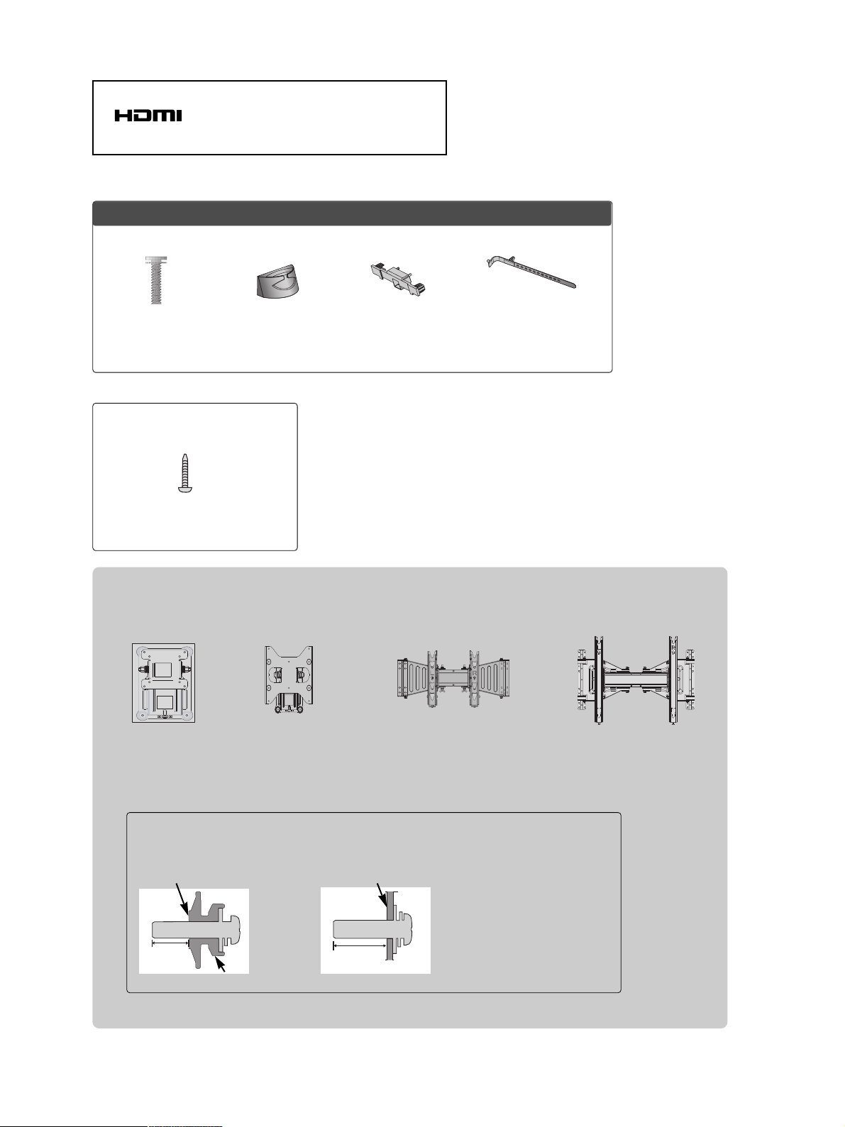
Wall Mounting Bracket(Separate purchase)
RW120
(19/22LH2***,
19/22LU5
***
)
RW230
(26/32LH2***, 32LF2***
26LU5
***, 32LH3***,
32LH6***, 32LH7***,
32SL8***
)
AW-47LG30M
(32/37/42LH2***, 32/42LF2***,
32/37/42/47LH3***,
37/42/47LH5***, 32/42LH6***,
32/37/42/47LH7***, 42/47LH9***,
32/42/47SL8***)
12mm
12mm
Use screws 12mm(+0.5/-0.5) long on the SET assembly side.(Separate purchase)
(
Only 42/47LH7***, 42/47SL8***
)
AW-55LH40M
(55LH5***, 55SL8***)
Set assembly side
(without guide spacer)
Set assembly side
(with guide spacer)
Guide spacer
HDMI, the HDMI logo and High-Definition
Multimedia Interface are trademarks or registered
trademarks of HDMI Licensing LLC.
Only 32/42/47/55SL8***
Cable management
clip
(Refer to p.23)
Protection Cover
(Refer to p.20)
x 8
Bolts for stand
assembly
(Refer to p.19)
(Except 55SL8***)
Cable Holder
(Refer to p.23)
1
ACCESSORIES
ACCESSORIES
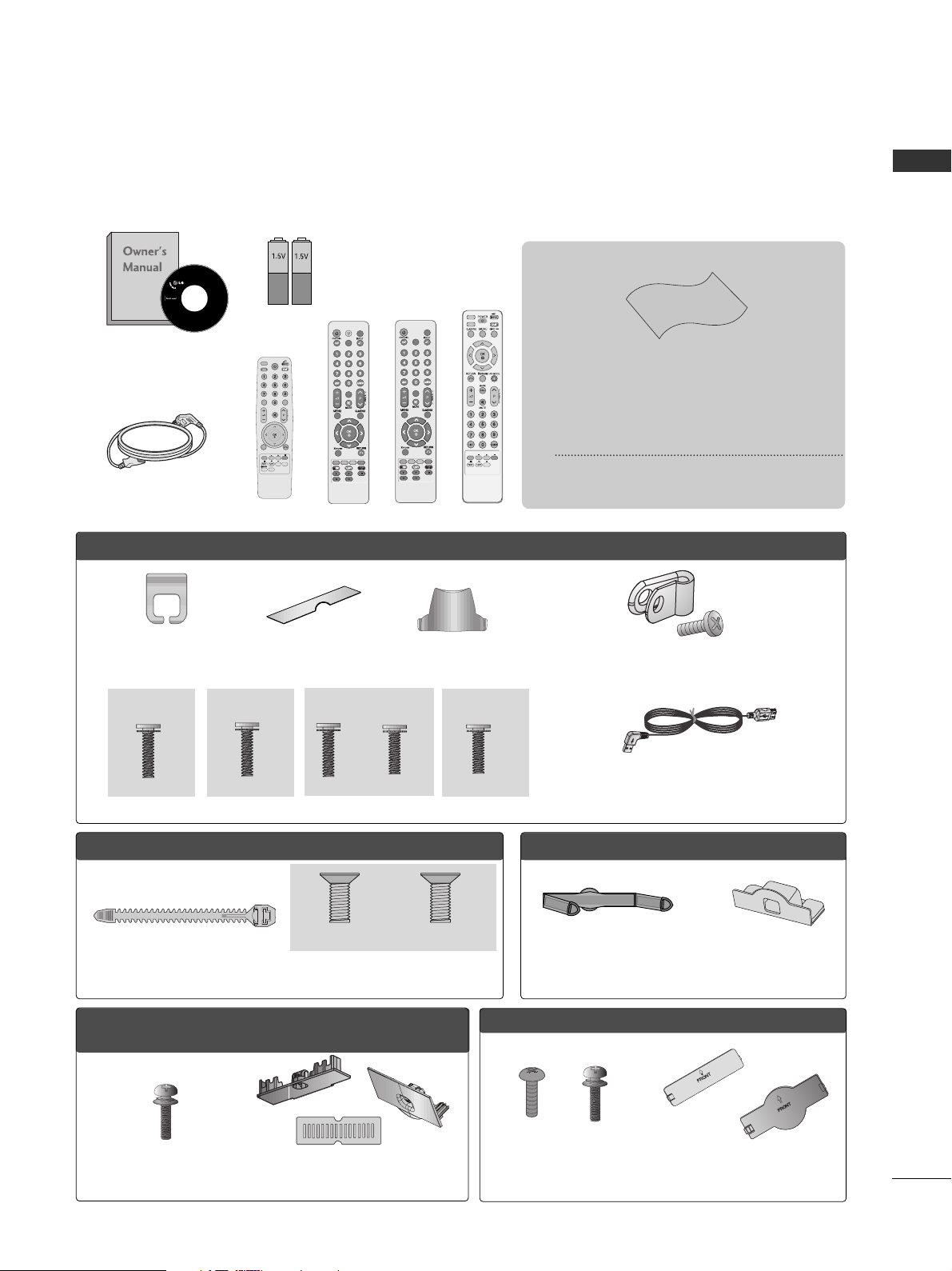
Ensure that the following accessories are included with your TV.
If an accessory is missing, please contact the dealer where you purchased the TV.
■
Here shown may be somewhat different from your TV.
Owner’s Manual
Batteries
Remote Control
Power Cord
Polishing Cloth
Polishing cloth for use on the screen.
This item is not included for all models.
* Lightly wipe any stains or fingerprints on
the surface of the TV with the polishing
cloth.
Do not use excessive force. This may cause
scratching or discolouration.
RARATIOTIO
SLEEPSLEEP
ENERGY SAVING
Cable management clip
(Refer to p.23)
Protection cover
(Refer to p.20)
bolts for stand assembly (Refer to p. 18)
OOnnllyy 1199//2222LLHH22******
Protection cover
(Refer to p.20)
Only 32/37/42/47LH7
***
AV MODEV MODE
ENERGYENERGY SA SAVINGVING
RETURN
MENU
Q.MENU
MARK
MUTEMUTE
POWERPOWER
LISTLIST
Q.VIEWQ.VIEW
RARATIOTIO
FAV
AV MODE
ENERGY SAVING
MUTE
LIST
Q.VIEW
or
Bolts for stand assembly
(Refer to p.17)
Cable Holder
(Refer to p.22)
OO nnllyy 1199 //2222 // 2266LL UU 55
** ****
Bolts for stand assembly
(Refer to p.18)
x 4
OOnnllyy 2266//3322//3377//4422LLHH22******,, 3322//3377//4422//4477LLHH33******,,
3377//4422//4477//5555LLHH55******,, 3322//4422LLHH66******,, 4422//4477LLHH99******
Protection cover
(Refer to p.20)
Cable management clip
(Refer to p.22)
Stand rear cover
(Refer to p.21)
(37LH7
***
only)
x 8
(42LH7
***
only)
x 3 x 4
M4x20 M4x16
M4x20
(32LH7
***
only)
x 7
M4x20
(Only 19/22LU5
***
)
(Only 26LU5
***
,)
x 2 x 3
Protective Bracket and Bolt for Power Cord
(Refer to P.25)
(Only 37/42/47LH7***)
(47LH7
***
only)
x 8
USB extension cable
Bolts for stand assembly
(Refer to p.17)
x 4
x 4
Protection Cover
(Refer to
p
.20)
OO nnllyy 3322 //4422 LL FF22** ****
Make sure to use the provided USB extension cable,
Which is specially designed for a slim fit.
or
M4x16
(Except 55LH5***)
or
POWERPOWER
TVTV
ON/OFFON/OFF
MARKMARK
FAV
AV MODEV MODE
or
POWERPOWER
TVTV
MARKMARK
FAV
AV MODEV MODE
or
CONTENTS
2
CONTENTS
ACCESSORIES
. . . . . . . . . . . . . . . . . . . . . . . . . . . . . . . . . . . . . . . . . . . .
1
PREPARATION
Front Panel Controls..................................................... 4
Back Panel Information .............................................. 12
Stand Installation......................................................... 17
Not Using the desk-type stand.................................19
Attaching the TV to a desk ........................................21
Swivel Stand ................................................................. 21
To Use The Stand Rear Cover...................................21
Positioning your display ............................................ 21
Back Cover for Wire Arrangement.......................... 22
Detaching Stand.......................................................... 24
Kensington Security System ......................................24
Careful Installation Advice .........................................25
How to Secure the Power Cable ............................. 25
Desktop Pedestal Installation................................... 25
Wall Mount: Horizontal Installation........................ 26
Antenna Connection .................................................. 27
EXTERNAL EQUIPMENT SETUP
HD Receiver Setup...................................................... 28
DVD Setup......................................................................31
VCR Setup..................................................................... 33
Other A/V Source Setup............................................35
External Stereo Setup ................................................ 36
AV Output Setup ........................................................ 37
Usb in Setup ..................................................................38
PC Setup........................................................................ 39
- Screen Setup for PC Mode .............................. 42
WATCHING TV / PROGRAMME CONTROL
Remote Control Key Functions.................................46
Turning on the TV....................................................... 52
Programme Selection ................................................ 52
Volume Adjustment ................................................... 52
Quick Menu ................................................................. 53
On-Screen Menus Selection and Adjustment..... 54
Auto Programme Tuning............................................ 55
Manual Programme Tuning ....................................... 56
Programme Edit ........................................................... 58
Selecting the Programme List.................................. 60
Favourite Programme Setup...................................... 61
Input List........................................................................ 62
Input Label......................................................................63
..................................................................64
Key Lock......................................................................... 67
Initializing(Reset to original factory settings) ..... 68
AV Mode........................................................................ 69
TO USE THE BLUETOOTH
Precautions when using the Bluetooth................. 70
Setting the Bluetooth................................................. 71
Set TV PIN......................................................................72
Bluetooth headset
- Connecting a new Bluetooth headset .............73
- Connecting to Bluetooth headset already
registered................................................................... 73
-
Disconnecting the Bluetooth headset during use
....74
- When requesting to connect to TV from the
Bluetooth headset....................................................74
Managing Registered Bluetooth device ................ 75
My Bluetooth Information. ........................................76
Receiving photos from external Bluetooth device .........
77
Listening to the musics from external Bluetooth device
77
TO USE A USB DEVICE
When connecting the USB device.......................... 78
Photo List ...................................................................... 79
Music List........................................................................83
Movie List .......................................................................86
Divx Registration Code ...............................................89
Deactivation...................................................................90

CONTENTS
3
PICTURE CONTROL
Picture Size (Aspect Ratio) Control....................... 91
Energy Saving ................................................... 93
Preset Picture Settings
- Picture Mode-Preset............................................ 94
Manual Picture Adjustment
- Picture Mode-User option................................. 95
Picture Improvement Technology........................... 96
Expert Picture Control............................................... 97
Picture Reset.............................................................. 100
LED Local Dimming ................................................... 101
Power Indicator ...........................................................102
Demo Mode................................................................ 103
Mode Setting ............................................................. 104
SOUND & LANGUAGE CONTROL
Auto Volume Leveler..................................................105
Preset Sound Settings - Sound Mode................. 106
Sound Setting Adjustment - User Mode ............ 107
SRS TruSurround XT ................................................ 107
Ultra Sound ................................................................ 108
Clear Voice ll............................................................... 109
Balance.......................................................................... 110
TV Speakers On/ Off Setup.................................... 111
Selecting Audio Out.................................................. 112
Audio Reset...................................................................113
I/II
- Stereo/Dual Reception...................................... 114
- NICAM Reception ............................................................ 115
- Speaker Sound Output Selection................... 115
On-Screen Menu Language Selection........................ 116
TIME SETTING
Clock Setup ................................................................. 117
Auto On/ Off Timer Setting.....................................118
Sleep Timer Setting ................................................... 118
TELETEXT
Switch on/off .............................................................. 119
SIMPLE Text................................................................. 119
TOP Text....................................................................... 119
FASTEXT.......................................................................120
Special Teletext Functions ...................................... 120
APPENDIX
Troubleshooting......................................................... 121
Maintenance ...............................................................123
Product Specifications............................................. 124
IR Codes ...................................................................... 129
External Control Device Setup .............................. 131
PREPARATION
4
PREPARATION
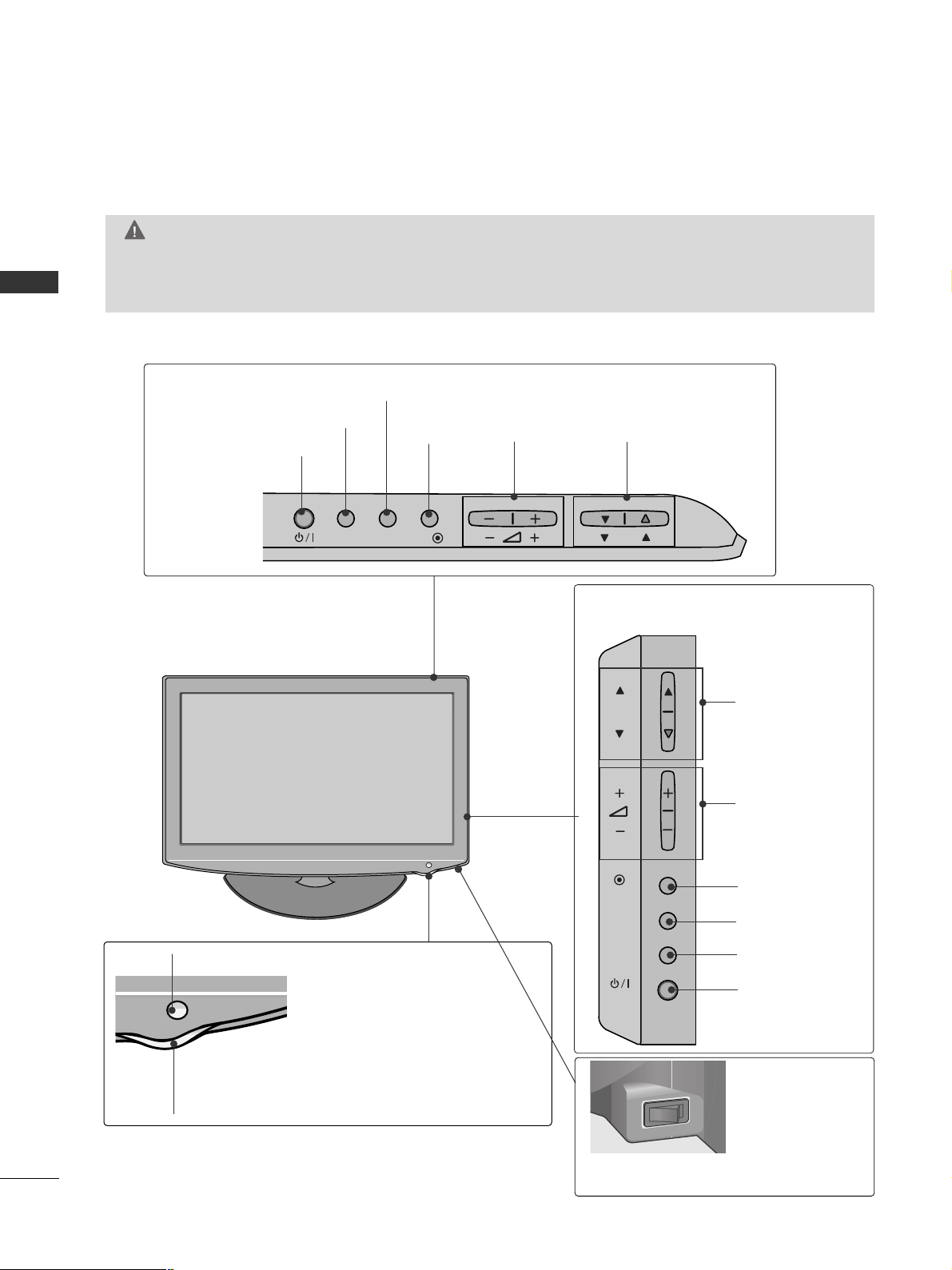
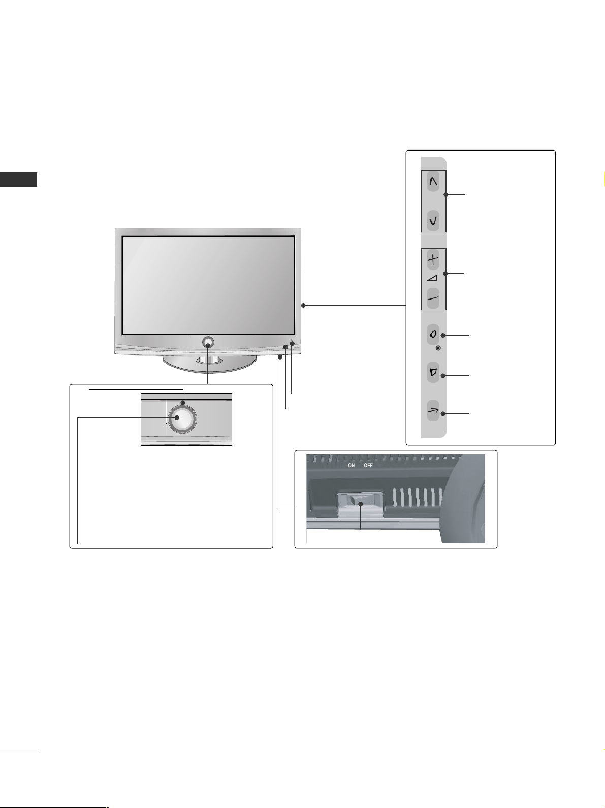
FRONT PANEL CONTROLS
■
Here shown may be somewhat different from your TV.
Only 32/37/42LH2***,
32/37/42/47LH3***
PROGRAMME
VOLUME
OK
Only 19/22/26LH2***
MENU
POWER
INPUT
INPUT
MENU
OK
P
PROGRAMME
VOLUME
OK
MENU
INPUT
POWER
Remote Control Sensor
Power/Standby Indicator
• Illuminates red in standby mode.
• Illuminates blue when the TV is switched on.
ON OFF
Only 19/22/26/32/37/42LH2***, 32/37/42/47LH3***
Main Power Switch
GG
When the TV cannot be turned on with the remote control, press the main power button on the TV.
(When the power is turned off with the main power button on the TV, it will not be turned on with the
remote control.)
CAUTION
Except 19/22LH2***
INPUT
MENU
OK
P
5
PREPARATION
■
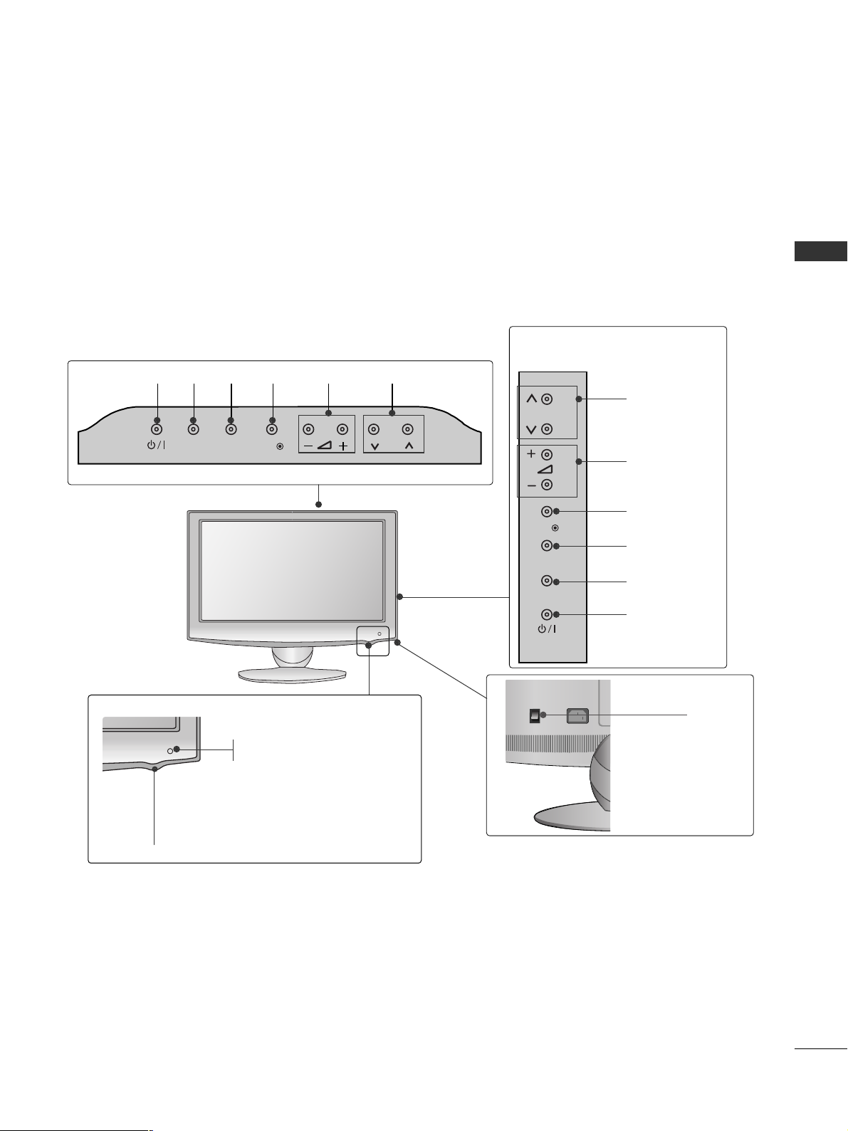
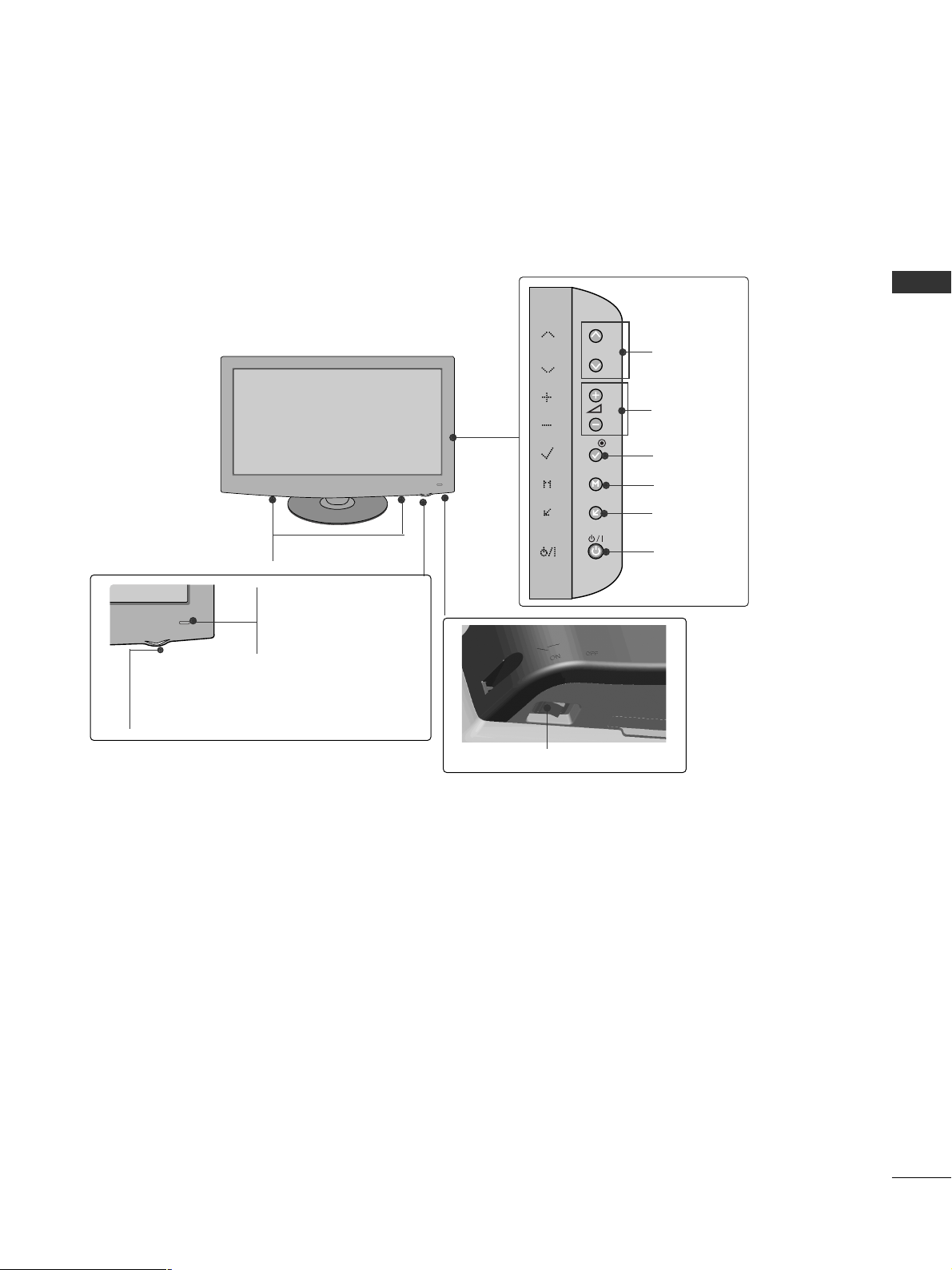
Here shown may be somewhat different from your TV.
Only 19/22/26LU5
***
P
PROGRAMME
VOLUME
OK
MENU
INPUT
POWER
Only 19/22LU5***
Only 26LU5***
VOLUME
POWER
INPUT MENU OK
PROGRAMME
Main
Power
Switch
ON
OFF
P
Remote Control Sensor
Power/Standby Indicator
Illuminates red in standby mode.
Illuminates white when the TV is switched on.
INPUT
MENU
OK
P
P
OK
MENU
INPUT
6
PREPARATION
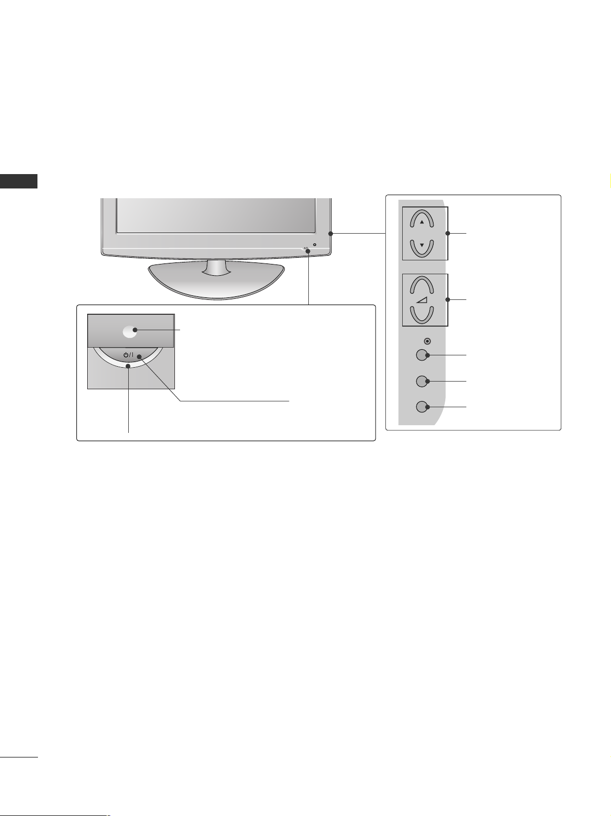
PREPARATION
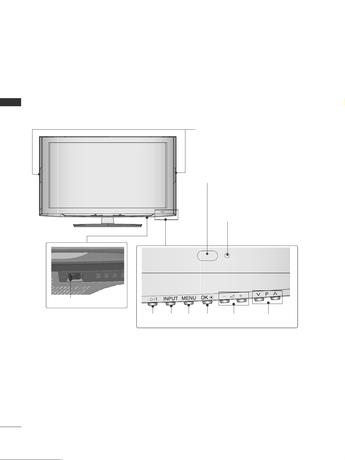
PROGRAMME
VOLUME
OK
MENU
INPUT
POWER Button
Power/Standby Indicator
• illuminates red in standby mode.
• illuminates blue when the TV is switched on.
Remote Control Sensor
Only 32/42LF2
***
■
Here shown may be somewhat different from your TV.
P
+
-
OK
MENU
INPUT
7
PREPARATION
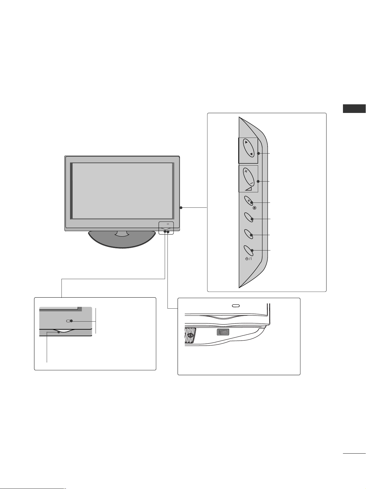
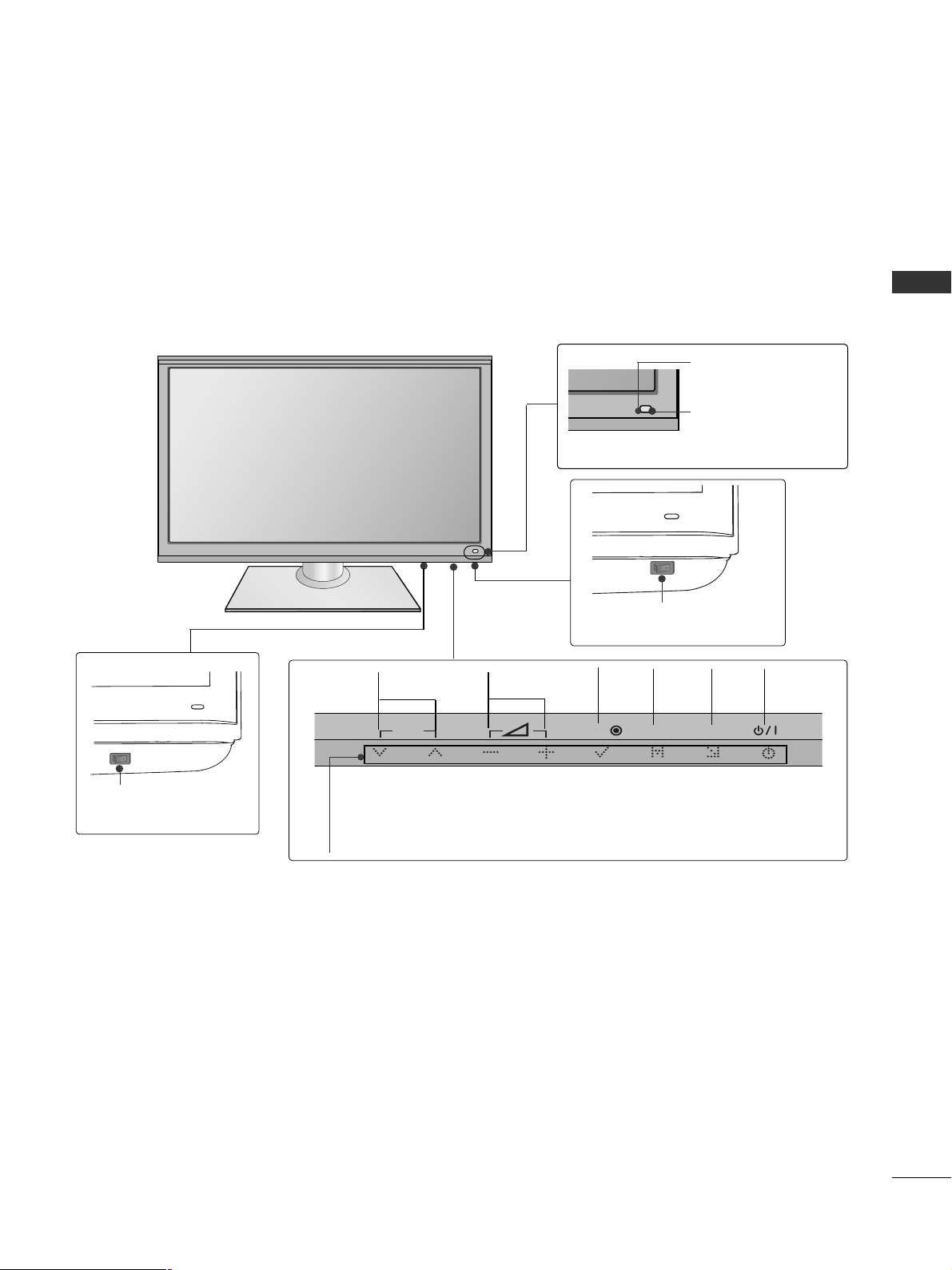
Only 37/42/47/55LH5
***
■
Here shown may be somewhat different from your TV.
PROGRAMME
VOLUME
OK
MENU
INPUT
POWER
Remote Control Sensor
Intelligent Sensor
Adjusts picture according to
the surrounding conditions.
Power/Standby Indicator
• Illuminates red in standby mode.
• Illuminates blue when the TV is switched on.
Main Power Switch
P
OK
MENU
INPUT
OFF ON
8
PREPARATION
PREPARATION
Only 32/37/42/47LH7
***
■
Here shown may be somewhat different from your TV.
P
P
OK
MENU
INPUT
P
PROGRAMME
VOLUME
OK
MENU
INPUT
Intelligent Sensor
Adjusts picture according to
the surrounding conditions
POWER(Touch Sensor)
Power/Standby Indicator
• Illuminates red in standby mode.
• Illuminates Whitish when the TV is switched on.
Note: You can adjust
PP ooww ee rr IInndd ii ccaatt oorr
in the
OPTION menu.
Moving LED
Main Power Switch
Remote Control Sensor
9
PREPARATION
Only 42/47LH9
***
PROGRAMME
VOLUME
OK
MENU
INPUT
POWER
Remote Control Sensor
Intelligent Sensor
Adjusts picture according to
the surrounding conditions.
Power/Standby Indicator
• Illuminates red in standby mode.
•
Illuminates white when the TV is switched on.
SPEAKER
Main Power Switch
■
Here shown may be somewhat different from your TV.
OK
MENU
INPUT
P
10
PREPARATION
PREPARATION
■
Here shown may be somewhat different from your TV.
Only
32/42LH6***
PROGRAMMEVOLUMEMENU OKINPUTPOWER
Remote Control Sensor
Intelligent Sensor
Adjusts picture according to the surrounding conditions.
Power/Standby Indicator
•
Illuminates red in standby mode.
• Illuminates blue when the TV is switched on.
Main Power Switch
Power Indicator(Only 42LH6***)
• Illuminates blue when the TV is switched on.
11
PREPARATION
Only 32/42/47/55SL8***
■
Here shown may be somewhat different from your TV.
Main Power Switch
OFF ON
PROGRAMME VOLUME
MENU
OK
INPUT
POWER
(Only 42/47/55SL8
***
)
Main Power Switch
OFFON
(Only 32SL8
***
)
Intelligent Sensor
Adjusts picture according
to the surrounding
conditions.
Remote Control
Sensor
Power/Standby Indicator
•
Illuminates red in standby mode.
•
Illuminates blue when the TV is switched on.
P
OK
MENU
INPUT
12
PREPARATION
PREPARATION
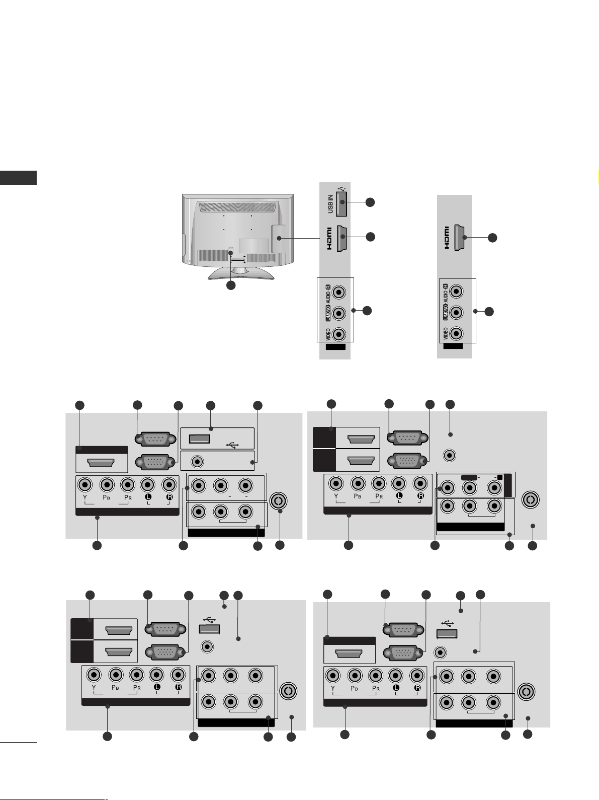
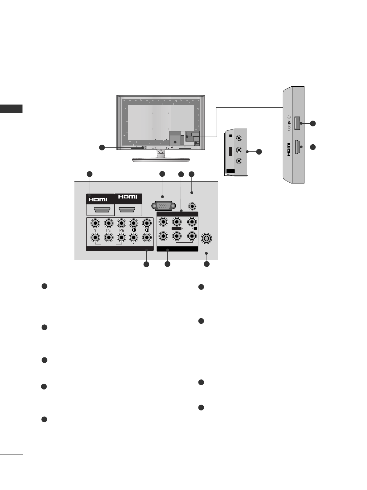
BACK PANEL INFORMATION
■
Here shown may be somewhat different from your TV.
Only 19/22/26/32/37/42LH2***, 32/42LF2
***,
32/37/42/47LH3***
(Refer to p.13)
COMPONENT IN
AUDIO
VIDEO
L(L(MONO)MONO)
R
AUDIOAUDIO
AV IN
VIDEOVIDEO
IN
OUT
VARIABLE AUDIO OUTVARIABLE AUDIO OUT
ANTENNA IN
HDMI/DVI IN
RGB IN
(PC)
RS-232C IN
(CONTROL)
AUDIO IN
(RGB/DVI)
USB IN
SERVICE ONLY
3
2
7
9
L( MONO)
R
AUDIO
VIDEO
VARIABLE AUDIO OUT
ANTENNA IN
AUDIO
VIDEO
L(L(MONO)MONO)
R
AUDIOAUDIO
AV
VIDEOVIDEO
IN
OUT
VARIABLE AUDIO OUTVARIABLE AUDIO OUT
ANTENNA
IN
HDMI
/DVI IN
RGB IN
(PC)
RS-232C IN
(CONTROL)
AUDIO IN
(RGB/DVI)
USB IN
SERVICE ONLY
HDMI
1
2
COMPONENT IN
4
5
6
10
8
Only 26/32/37/42LH20**
Only 19/22LH2***
Only 32/37/42/47LH3***, 32/37/42LH23**
6
3
2
4
5
7
9
10
8
L( MONO)
R
AUDIO
VIDEO
VARIABLE AUDIO OUT
ANTENNA IN
L( MONO)
R
AUDIO
VIDEO
VARIABLE AUDIO OUT
ANTENNA
IN
COMPONENT IN
AUDIO
VIDEO
ANTENNA
IN
HDMI
/DVI IN
RGB IN
(PC)
RS-232C IN
(CONTROL)
AUDIO IN
(RGB/DVI)
HDMI
1
2
AV OUT
L/L/MONOMONO
R
AUDIOAUDIO
VIDEOVIDEO
VARIABLE AUDIO OUTVARIABLE AUDIO OUT
AV IN1
Only 32/37/42/47LH3***, 32/37/42LH23**
6
3
2
4
7
9
10
8
AV IN2
IN 3
2
8
11
1
MONO)
AUDIO
VIDEO
VARIABLE AUDIO OUT
3
2
7
9
4
5
6
10
8
Only 32/42LF2***
Only 32/42LF2***
AV IN2
IN 2
2
8
HDMI/DVI IN
1
VIDEO
COMPONENT IN
RS-232C IN
(CONTROL)
RGB IN
AUDIO
(PC)
USB IN
SERVICE ONLY
VIDEO
AUDIO IN
(RGB/DVI)
AUDIO
L(L(MONO)
VARIABLE AUDIO OUT
R
IN1
OUT
ANTENNA
IN
AV
13
PREPARATION
AV IN2
IN 3
2
8
Only 26LU5***
ON
OFF
1
Power Cord Socket
This TV operates on an AC power. The voltage is
indicated on the Specifications page. Never
attempt to operate the TV on DC power.
HDMI Input
Connect a HDMI signal to HDMI IN.
Or DVI(VIDEO)signal to HDMI/DVI port with DVI
to HDMI cable.
RS-232C IN PORT
Connect to the RS-232C port on a PC.
This port is used for Service or Hotel mode.
RGB IN Input
Connect the output from a PC.
SERVICE ONLY PORT
RGB/DVI Audio Input
Connect the audio from a PC.
Component Input
Connect a component video/audio device to
these jacks.
Audio/Video Input
Connect audio/video output from an external
device to these jacks.
AV Output
Connect second TV or monitor to the AV OUT
socket on the TV.
Variable Audio Output
Connect an external amplifier or add a subwoofer
to your surround sound system.
Antenna Input
Connect RF antenna to this jack.
USB IN Input
Connect USB storage device to this jack.
1
2
3
4
5
6
8
9
10
11
7
11
2
8
1
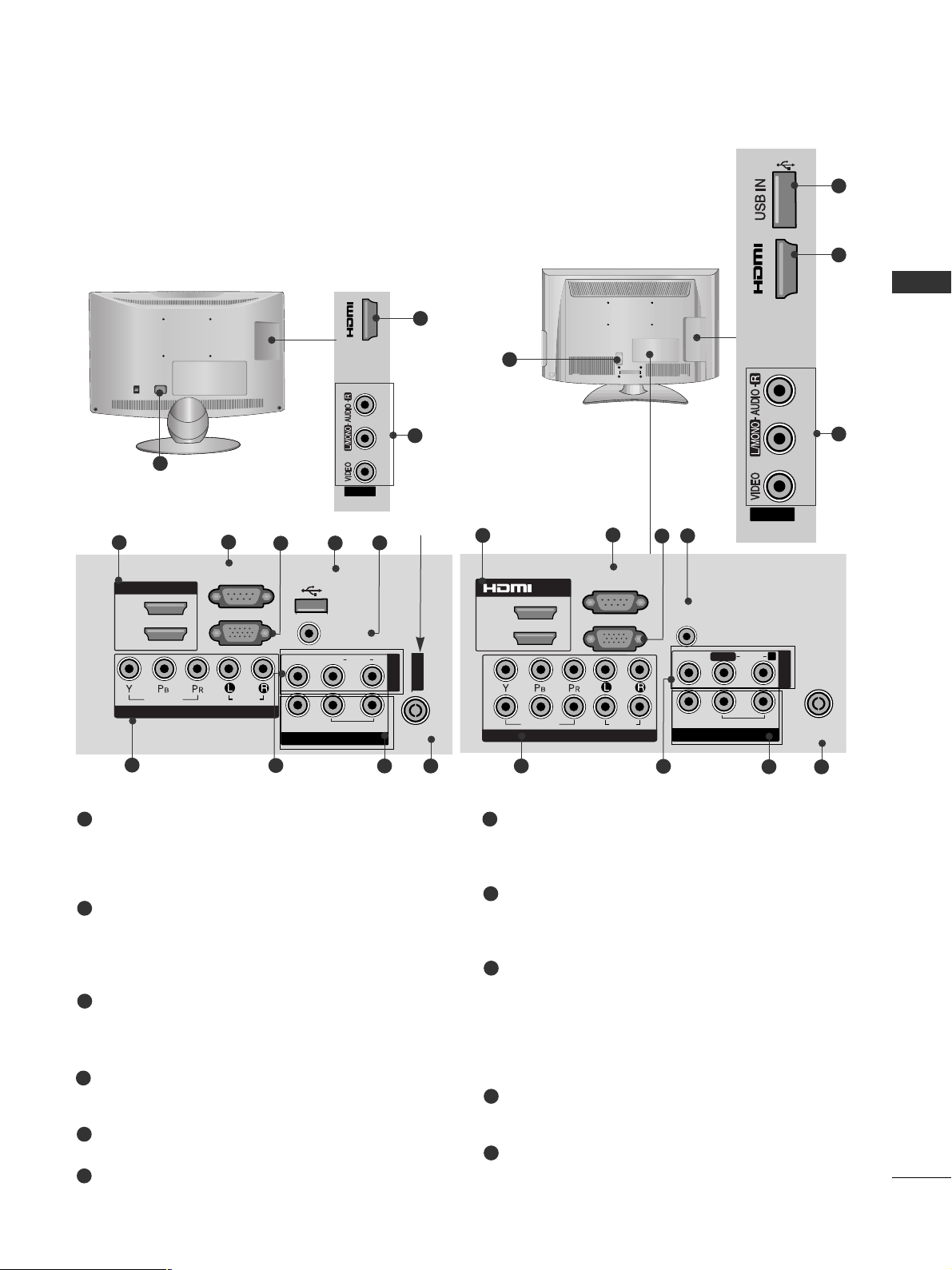
Only 19/22/26LU5***, 37/42/47/55LH5
***
, 42/47LH9***
■
Here shown may be somewhat different from your TV.
AV OUT
L/L/MONOMONO
R
AUDIOAUDIO
VIDEOVIDEO
VARIABLE AUDIO OUTVARIABLE AUDIO OUT
ANTENNA
IN
RGB IN
(PC)
RS-232C IN
(CONTROL)
AUDIO IN
(RGB/DVI)
1
2
COMPONENT IN
AUDIO
VIDEO
1(DVI)
2
AV IN1
/DVI IN
3
2
7
9
4
6
10
8
Only 19/22/26LU5***
COMPONENT IN
AUDIO
VIDEO
HDMI/DVI IN
RGB IN
(PC)
RS-232C IN
(CONTROL)
AUDIO IN
(RGB/DVI)
USB IN
SERVICE ONLY
L(L(MONO)MONO)
R
AUDIOAUDIO
VIDEOVIDEO
1(DVI)
2
ANTENNA
IN
AV OUT
VARIABLE AUDIO OUTVARIABLE AUDIO OUT
AV IN
3
2
7
9
4
5
6
10
8
ANTENNA
IN
AV IN1
Only 26LU5***
IN 3
AV IN2
14
PREPARATION
PREPARATION
1
Only 32/42LH6***
Power Cord Socket
This TV operates on an AC power. The voltage is
indicated on the Specifications page. Never
attempt to operate the TV on DC power.
HDMI Input
Connect a HDMI signal to HDMI IN.
Or DVI(VIDEO)signal to HDMI/DVI port with DVI
to HDMI cable.
RGB IN Input
Connect the output from a PC.
RGB/DVI Audio Input
Connect the audio from a PC.
Component Input
Connect a component video/audio device to
these jacks.
Audio/Video Input
Connect audio/video output from an external
device to these jacks.
AV Output
Connect second TV or monitor to the AV OUT
socket on the TV.
Variable Audio Output
Connect an external amplifier or add a subwoofer
to your surround sound system.
Antenna Input
Connect RF antenna to this jack.
USB IN Input
Connect USB storage device to this jack.
1
2
3
4
5
7
6
8
9
6
MONO
AUDIO
VIDEO
VARIABLE AUDIO OUT
■
Here shown may be somewhat different from your TV.
2
5
7
3
4
8
6
9
2
1(DVI)
2
1
2
/DVI IN
RGB IN
VIDEO
COMPONENT IN
(PC)
AUDIO
AUDIO IN
(RGB/DVI)
VIDEO
R
AUDIO
L/L/MONO
VARIABLE AUDIO OUT
AV OUT
IN 3
AV IN1
ANTENNA
IN
AV IN2
15
PREPARATION
1
2
AUDIO IN
(RGB/DVI)
RGB IN
(PC)
RGB IN
COMPONENT IN
AUDIO
VIDEO
L/L/MONOMONO
R
AUDIOAUDIO
VIDEOVIDEO
VARIABLE AUDIO OUTVARIABLE AUDIO OUT
AV IN1
AV OUT
AV IN2
ANTENNA IN
RS-232C IN
(CONTROL)
2
5
7
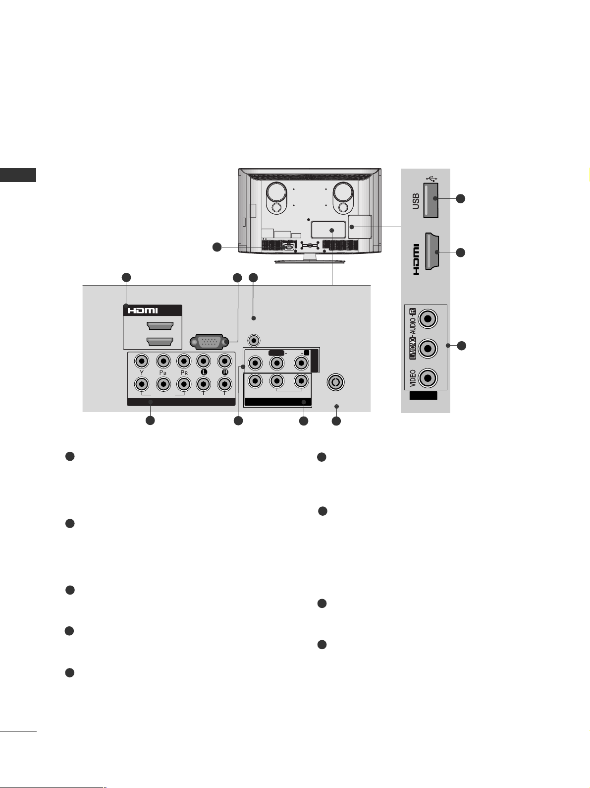
1
Only 32/37/42/47LH7
***
Power Cord Socket
This TV operates on an AC power. The voltage is
indicated on the Specifications page. Never
attempt to operate the TV on DC power.
RGB IN Input
Connect the output from a PC.
RGB/DVI Audio Input
Connect the audio from a PC.
Audio/Video Input
Connect audio/video output from an external
device to these jacks.
RS-232C IN PORT
Connect to the RS-232C port on a PC.
This port is used for Service or Hotel mode.
Component Input
Connect a component video/audio device to
these jacks.
AV Output
Connect second TV or monitor to the AV OUT
socket on the TV.
Variable Audio Output
Connect an external amplifier or add a subwoofer
to your surround sound system.
Antenna Input
Connect RF antenna to this jack.
USB IN Input
Connect USB storage device to this jack.
HDMI Input
Connect a HDMI signal to HDMI IN.
Or DVI(VIDEO)signal to HDMI/DVI port with DVI
to HDMI cable.
1
2
3
4
6
7
8
4
3
6
8
9
5
9
■
Here shown may be somewhat different from your TV.
/DVI IN
3
2
1(DVI)
16
PREPARATION
PREPARATION
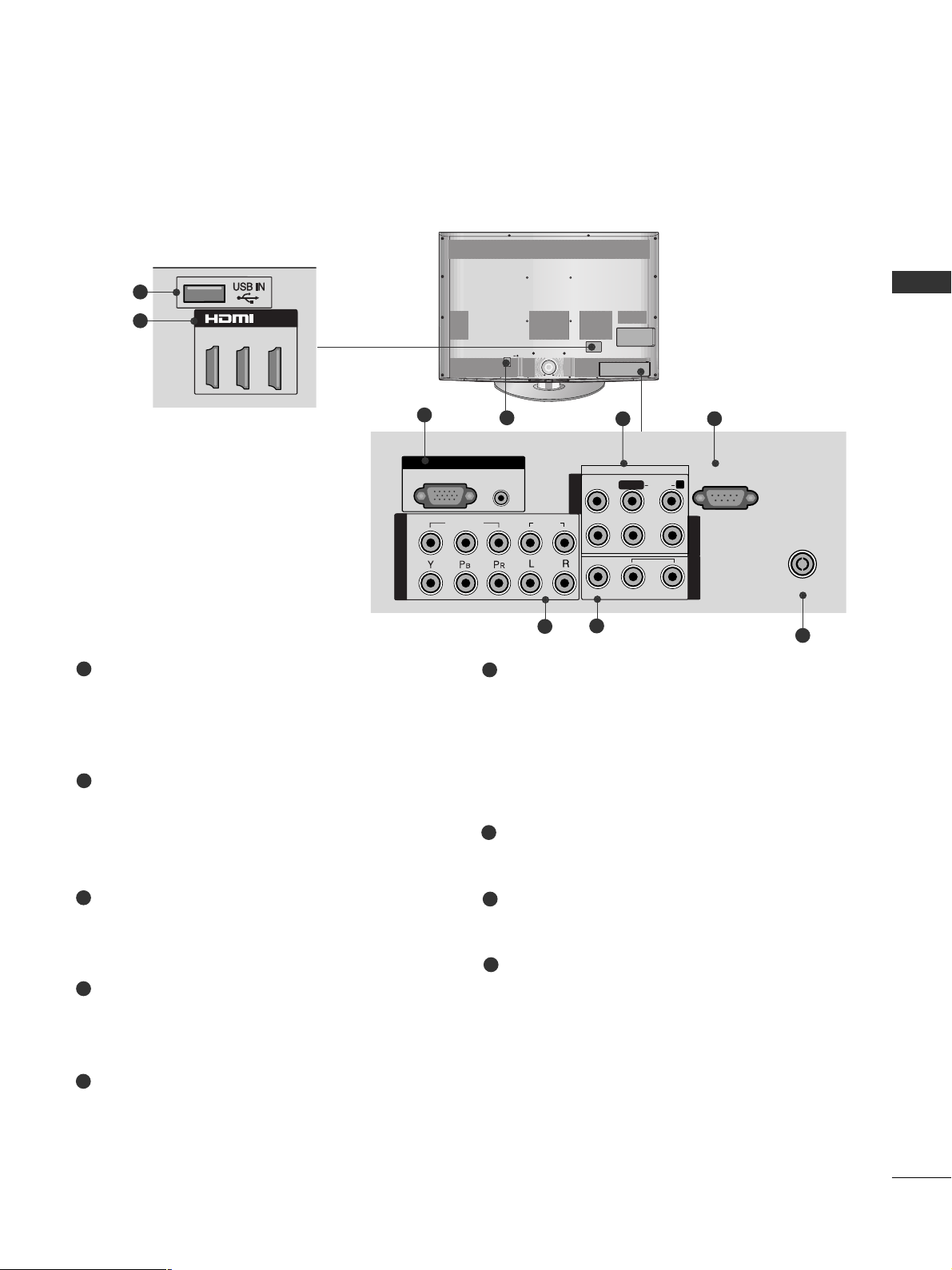
Only
32/42/47/55SL8***
Power Cord Socket
This TV operates on an AC power. The voltage is
indicated on the Specifications page. Never
attempt to operate the TV on DC power.
HDMI IN Input
Connect a HDMI signal to HDMI IN. Or DVI (VIDEO)
signal to HDMI/DVI port with DVI to HDMI cable.
RGB IN Input
Connect the output from a PC.
Audio/Video Input
Connect audio/video output from an external
device to these jacks.
RGB/DVI Audio Input
Connect the audio from a PC or DTV.
Component Input
Connect a component video/audio device to
these jacks.
AV Output
Connect second TV or monitor to the AV OUT
socket on the TV.
Variable Audio Output
Connect an external amplifier or add a subwoofer
to your surround sound system.
Antenna Input
Connect RF antenna to this jack.
USB IN Input
Connect USB storage device to this jack.
1
2
3
4
5
6
7
8
9
■
Here shown may be somewhat different from your TV.
AV IN 2
L/MONO
R
AUDIOAUDIO
VIDEOVIDEO
4
AV IN 2
L/MONO
R
AUDIO
VIDEO
1
AV IN 2
L/MONO
R
AUDIO
VIDEO
IN 3
9
2
AV IN 2
L/ MONO
R
AUDIO
VIDEO
MONO
AUDIO
VIDEO
VARIABLE AUDIO OUT
3
2
5
6
8
4
7
IN
/DVI IN
2
2
1
VIDEO
COMPONENT IN
1
AUDIO
RGB IN
VIDEO
(PC)
AUDIO IN
(RGB/DVI)
AV IN 1
AUDIO
L/L/MONO
VARIABLE AUDIO OUT
AV OUT
R
ANTENNA
IN
17
PREPARATION
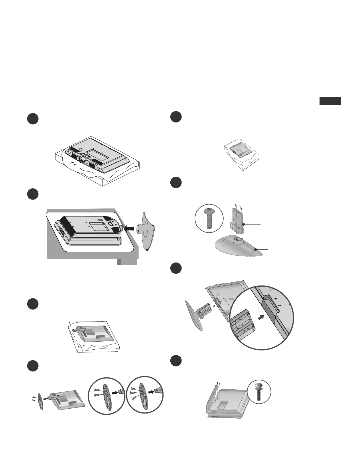
STAND INSTALLATION
■
Here shown may be somewhat different from your TV.
When assembling the desk type stand, check whether the bolt is fully tightened. (If not tightened fully, the product can
tilt forward after the product installation.) If you tighten the bolt with excessive force, the bolt can deviate from abrasion
of the tightening part of the bolt.
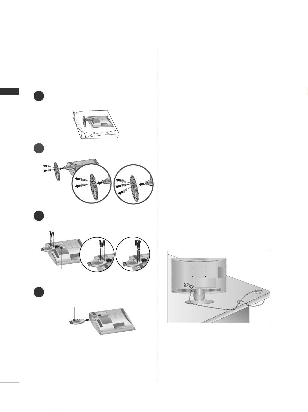
Only 19/22/26LU5
***
1
2
Carefully place the TV screen side down on a cushioned surface to protect the screen from damage.
Fix the 2 or 3 bolts securely using the holes as
shown.
1
Carefully place the TV screen side down on a cushioned surface to protect the screen from damage.
2
Assemble the TV as shown.
Only 19/22LH2
***
Cover Base
(Only 26LU5
***
)
1
3
4
Carefully place the TV screen side down on a
cushioned surface to protect the screen from
damage.
2
Assemble the parts of the
SStt aa nndd BBooddyy
with
the
SStt aa nndd BBaass ee
of the TV.
Assemble the TV as shown.
Fix the 4 bolts securely using the holes in the
back of the TV.
Stand Body
Stand Base
Only 32/42LF2***
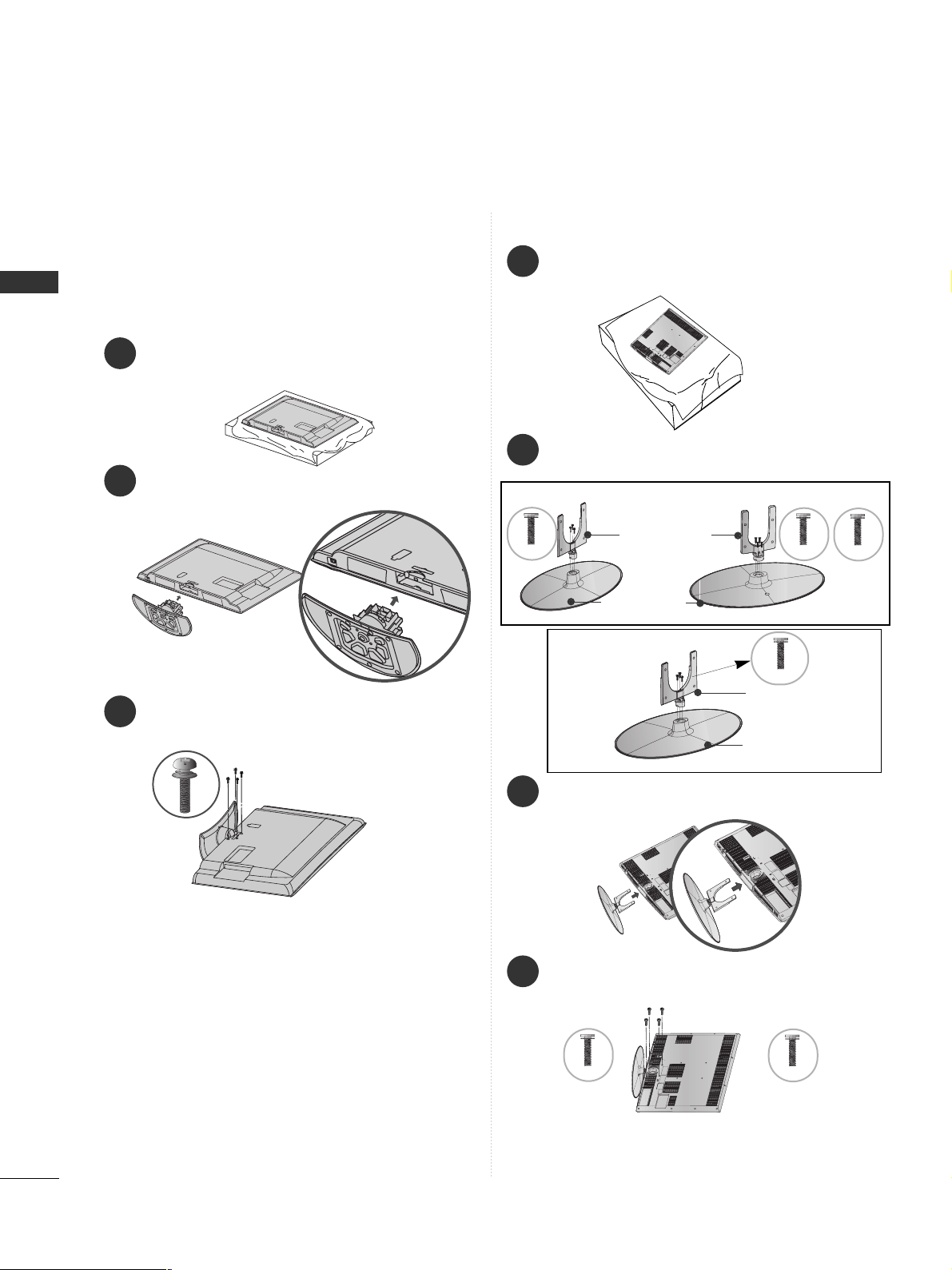
18
PREPARATION
PREPARATION
1
2
3
Carefully place the TV screen side down on a cushioned
surface to protect the screen from damage.
Assemble the TV as shown.
Fix the 4 bolts securely using the holes in the
back of the TV.
Only 26/32/37/42LH2***,
32/37/42/47LH3***,
37/42/47LH5
***
, 32/42LH6
***,
42/47LH9***
Only 32/37/42/47LH7
***
1
3
4
Carefully place the TV screen side down on a cushioned surface to protect the screen from damage.
2
Assemble the parts of the
SStt aa nndd BBooddyy
with
the
SStt aa nndd BBaass ee
of the TV.
Assemble the TV as shown.
Fix the 4 bolts securely using the holes in the
back of the TV.
32LH7
***
Stand Body
Stand Base
42LH7
***
47LH 7
***
Stand Body
Stand Base
32/37LH7
***
42/47LH7
***
M4x20
M4x20
M4x16
M4x20
M4x16
M4x20
37L H7
***
■
Image shown may differ from your TV.
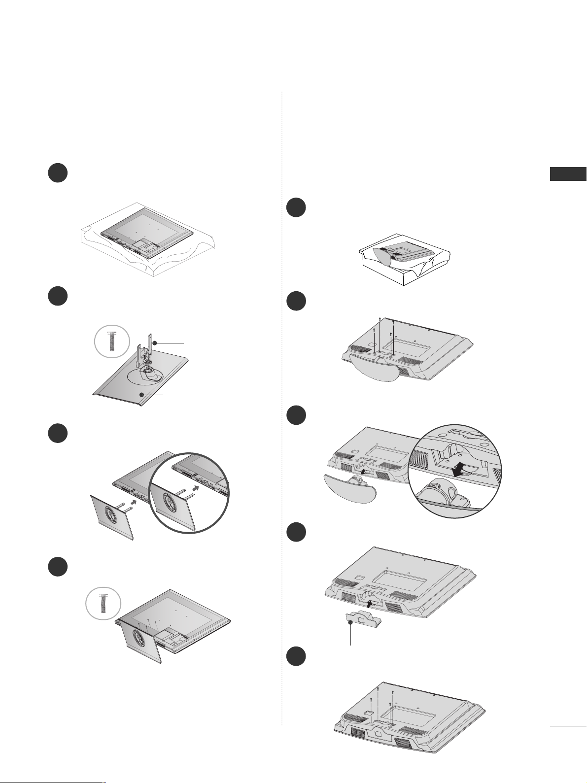
19
PREPARATION
1
3
4
Carefully place the TV screen side down on a cushioned surface to protect the screen from damage.
2
Assemble the parts of the
SStt aa nndd BBooddyy
with
the
SStt aa nndd BBaass ee
of the TV.
Assemble the TV as shown.
Fix the 4 bolts securely using the holes in the
back of the TV.
Stand Body
Stand Base
■
Image shown may differ from your TV.
Only 32/42/47SL8***
■
Here shown may be somewhat different from your TV.
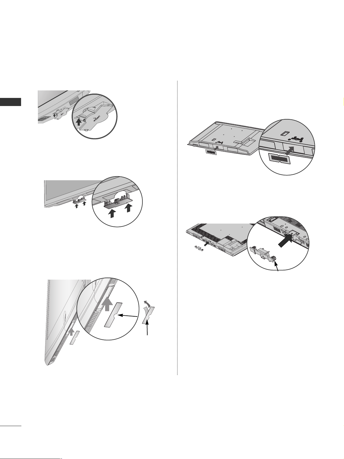
When installing the wall-mounted unit, use the protection cover.
NOT USING THE DESK-TYPE STAND
Loose the bolts from TV.
Insert the
PPrr oo tt eeccttiioonn CCoovveerr
into the TV.
Detach the
SStt aa nndd BBooddyy
from
TT VV
.
Fix the 4 bolts securely using the holes in the
back of the TV.
2
3
4
Only 19/22LH2
***
1
Carefully place the TV screen side down on a cushioned surface to protect the screen from damage.
5
Protection Cover
20
PREPARATION
PREPARATION
Only 26/32/37/42LH2***,
32/37/42/47LH3***, 37/42/47/55LH5***,
32/42LH6***
Only 32/37/42/47LH7
***
Insert the
PPRROOTTEECCTTIIOONN CCOOVVEE RR
into the TV
until clicking sound.
After removing the protection paper
from the protection cover, adhere it
to the TV as shown.
PROTECTION COVER
Insert the
PPRROOTTEECCTTIIOONN
CC OOVV EERR
into the TV
until clicking sound.
Only 32/42LF2***
After removing the protection paper from the protection cover, adhere it to the TV as shown.
Only
42/47LH9***
Insert the
PPRROOTTEECCTTIIOONN
CC OOVV EERR
into the TV until
clicking sound.
PROTECTION COVER
Only 32/42/47/55SL8***
21
PREPARATION
TO USE THE STAND REAR COVER (37/42/47LH7
***
only)
Install the
SSTTAANNDD RREEAARR CCOOVVEERR
as shown.
STAND REAR COVER
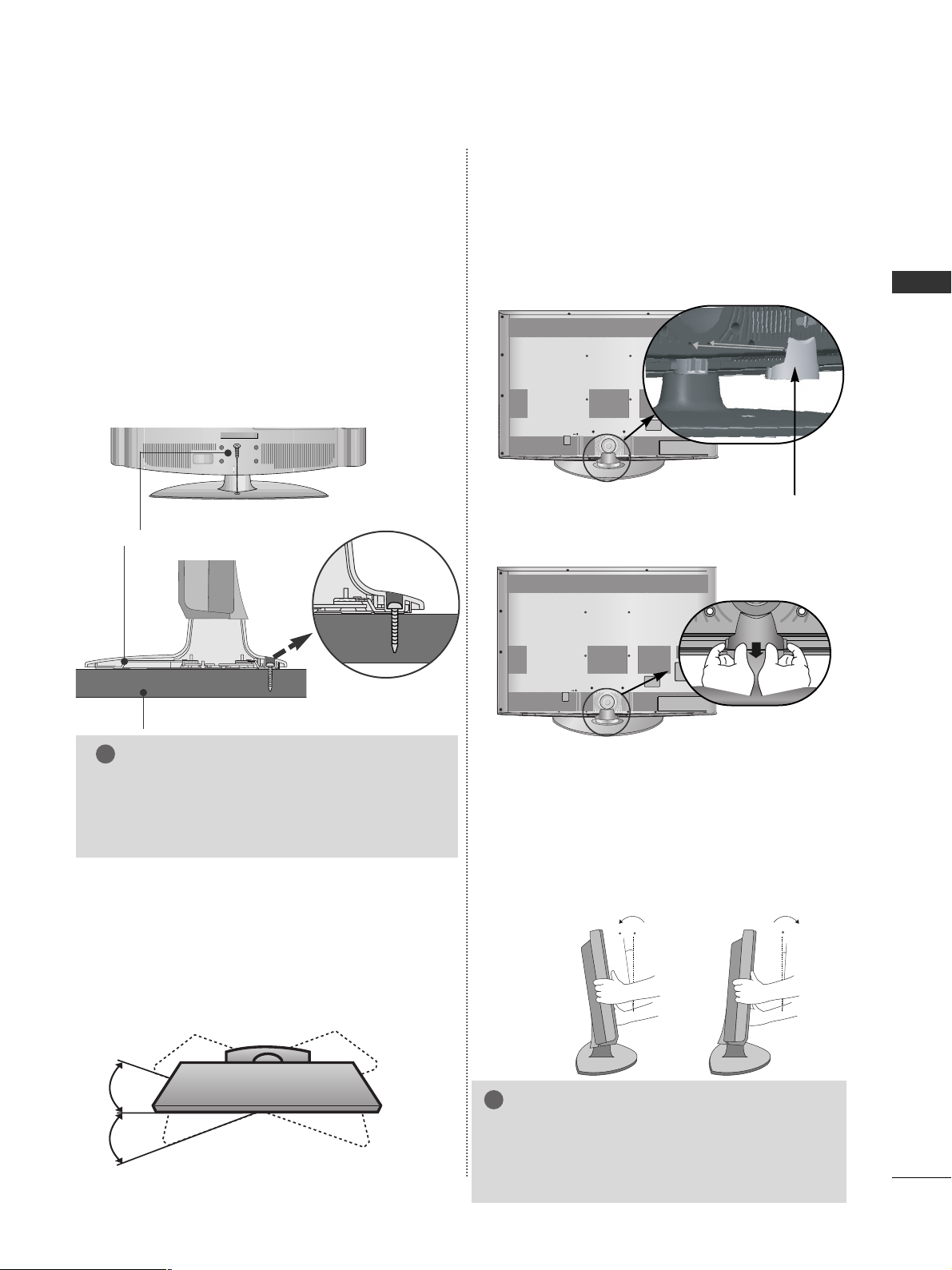
SWIVEL STAND
(Except 19/22/26LU5
***,
19/22LH2***
)
■
This feature is not available for all models.
■
After installing the TV, you can adjust the TV manually
to the left or right direction by 20 degrees to suit your
viewing position.
POSITIONING YOUR DISPLAY
(Only 19/22LH2***)
■
Here shown may be somewhat different from your TV.
■
Adjust the position of the panel in various ways for
maximum comfort.
• Tilt range
12
0
3
0
ATTACHING THE TV TO A DESK
■
Here shown may be somewhat different from your TV.
The TV must be attached to desk so it cannot be pulled
in a forward/backward direction, potentially causing
injury or damaging the product. Use only an attached
screw.
1-Screw (provided as parts of the product)
Desk
Stand
WARNING
!
G
To prevent TV from falling over, the TV should
be securely attached to the floor/wall per installation instructions. Tipping, shaking, or rocking the
machine may cause injury.
Only 26/32/37/42LH2
***,
32/42LF2***, 32/37/42LH3***,
26LU5***, 37/42LH5***,
32/42LH6***, 32/37LH7***,
42LH9***
■
Here shown may be somewhat different from your TV.
Grip the knob in your fingers and pull it.
NOTE
!
G
The following model is a fixed stand type
model without the Tilt and Swivel features so
excessive pressure may damage the set.
- 19/22/26LU5***
22
PREPARATION
PREPARATION
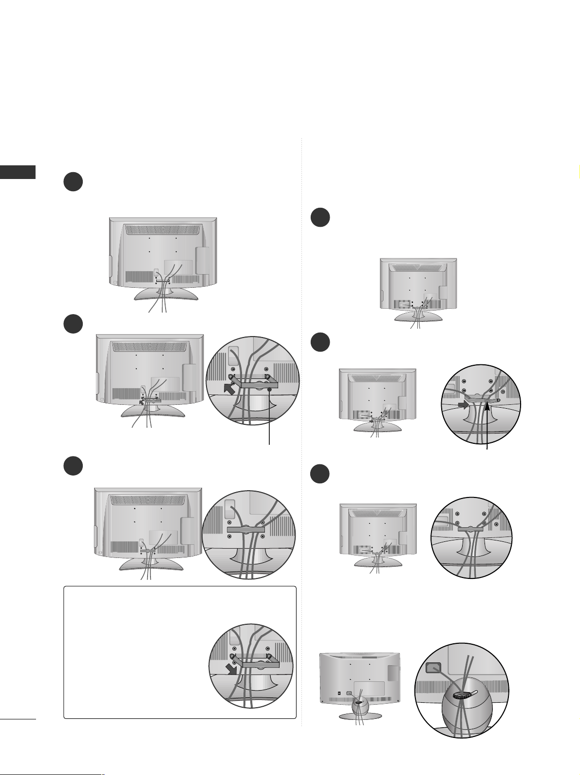
BACK COVER FOR WIRE ARRANGEMENT
■
Here shown may be somewhat different from your TV.
Connect the cables as necessary.
To connect additional equipment, see the
EXTERNAL EQUIPMENT SETUP section.
Fit the CABLE MANAGEMENT CLIP as shown.
Only 19/22LH2
***
How to remove the CABLE MANAGEMENT CLIP(
Only 19/22LH2
***
)
GG
Hold the CABLE MANAGEMENT CLIP with both hands
and pull it backward.
CABLE MANAGEMENT CLIP
Connect the cables as necessary.
To connect additional equipment, see the
External Equipment Setup section of the manual.
1
Open the
CC AABB LLEE MMAANNAAGGEE MMEE NNTT CCLLIIPP
as
shown and manage the cables.
2
CABLE MANAGEMENT CLIP
Fit the
CC AABB LLEE MMAANNAAGGEE MMEE NNTT CCLLIIPP
as
shown.
3
Only 19/22/26/32/37/42LH2***,
32/42LF2***, 32/37/42/47LH3***,
37/42/47/55LH5
***, 32/42LH6***,
42/47LH9***
1
Install the CABLE MANAGEMENT CLIP as shown.
2
3
Only 19/22/26LU5
***
After Connecting the cables as necessary, install
CABLE HOLDER as shown and bundle the cables.
23
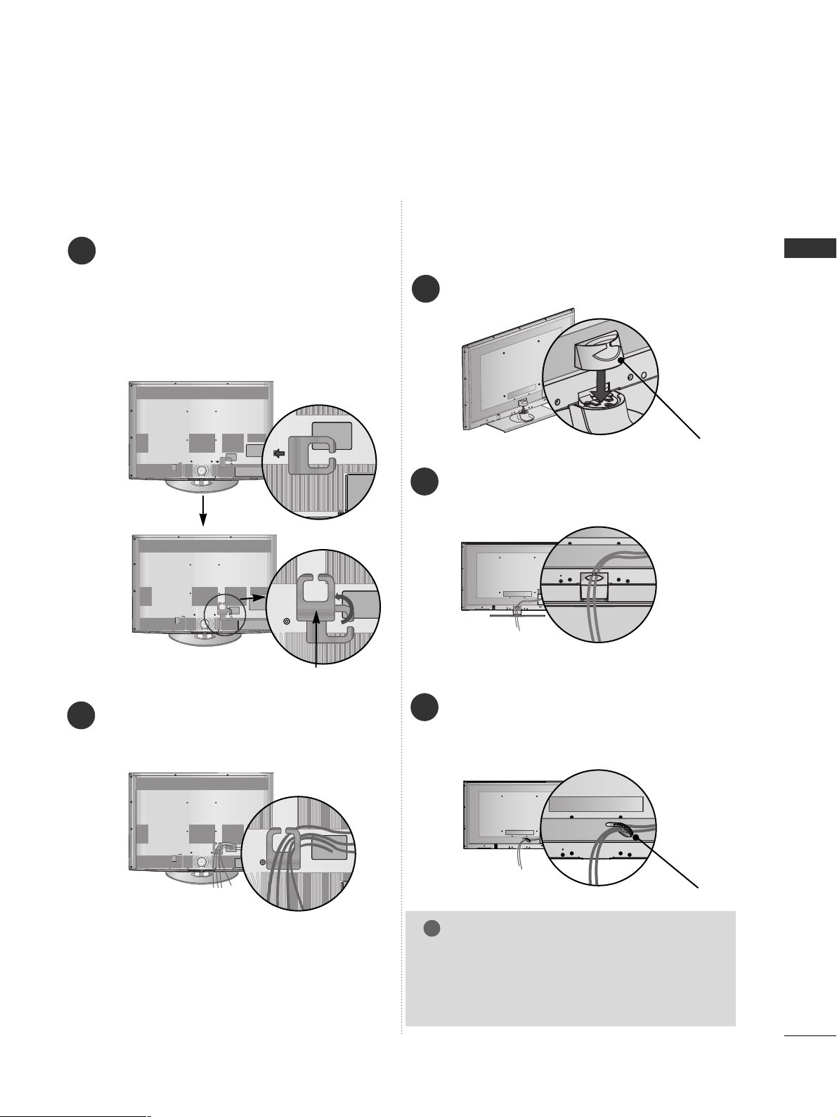
PREPARATION
Only 32/37/42/47LH7
***
1
2
Connect the cables as necessary.
To connect additional equipment, see the
EExxttee rrnnaall ee qquuii pp mm eenntt SSeettuupp
section.
Align the hole with the tab on the
CC AABBLLEE
MMAA NNAA GGEE MMEE NNTT CCLLIIPP
.
Turn the
CC AABB LLEE MMAANNAAGGEE MMEE NNTT CCLLIIPP
as
shown.
Note : that excessive force might cause dam-
age to the product when using Cable
Management clip.
CABLE MANAGEMENT CLIP
Only 32/42/47/55SL8***
Install the CABLE MANAGEMENT CLIP as
shown.
1
CABLE MANAGEMENT CLIP
Connect the cables as necessary. To connect
additional equipment, see the EXTERNAL
EQUIPMENT SETUP section.
2
NOTE
!
GG
Do not use the CABLE MANAGEMENT CLIP to
lift the TV.
- If the TV is dropped, you may be injured or the
TV may be damaged.
After Connecting the cables as necessary,
install CABLE HOLDER as shown and bundle
the cables. To connect additional equipment,
see the
EExxttee rrnnaall ee qquuii pp mm eenntt SSeettuupp
section.
1
CABLE HOLDER
FOR DESK-TYPE STAND
FOR WALL MOUNT
24
PREPARATION
PREPARATION
2
Loose the bolts and then detach the stand from
TV.
3
Loose the bolts and then detach the
CC oovvee rr
BBaass ee
from
TT VV
.
4
Detach the
SStt aa nndd BBooddyy
from
TT VV
.
Stand Body
DETACHING STAND
1
Carefully place the TV screen side down on a cushioned surface to protect the screen from damage.
Cover Base
Only 19/22/26LU5
***
(Only 26LU5
***
)
■
Here shown may be somewhat different from your TV.
(Only 26LU5
***
)
KENSINGTON SECURITY SYSTEM
■
This feature is not available for all models.
■
Here shown may be somewhat different from your TV.
The TV is equipped with a Kensington Security
System connector on the back panel. Connect the
Kensington Security System cable as shown below.
For the detailed installation and use of the
Kensington Security System, refer to the user’s guide
provided with the Kensington Security System.
For further information, contact http://www.kensing-
ton.com, the internet homepage of the Kensington
company. Kensington sells security systems for
expensive electronic equipment such as notebook
PCs and LCD projectors.
NOTE
- The Kensington Security System is an optional accessory.
NOTES
a. If the TV feels cold to the touch, there may be a
small “flicker” when when it is turned on.
This is normal, there is nothing wrong with TV.
b. Some minute dot defects may be visible on the
screen, appearing as tiny red, green, or blue spots.
However, they have no adverse effect on the monitor's performance.
c. Avoid touching the LCD screen or holding your finger(s)
against it for long periods of time.
Doing so may produce some temporary distortion
effects on the screen.
25
PREPARATION
A
The TV can be installed in various ways such as on
a wall, or on a desktop etc.
A
The TV is designed to be mounted horizontally.
Power Supply
Circuit breaker
EARTHING
Ensure that you connect the earth wire to prevent
possible electric shock. If grounding methods are not
possible, have a qualified electrician install a separate
circuit breaker.
Do not try to earth the TV by connecting it to telephone wires, lightening rods or gas pipes.
4 inches
4 inches
4 inches
4 inches
DESKTOP PEDESTAL INSTALLATION
For adequate ventilation allow a clearance of 4”
(10cm) all around the TV.
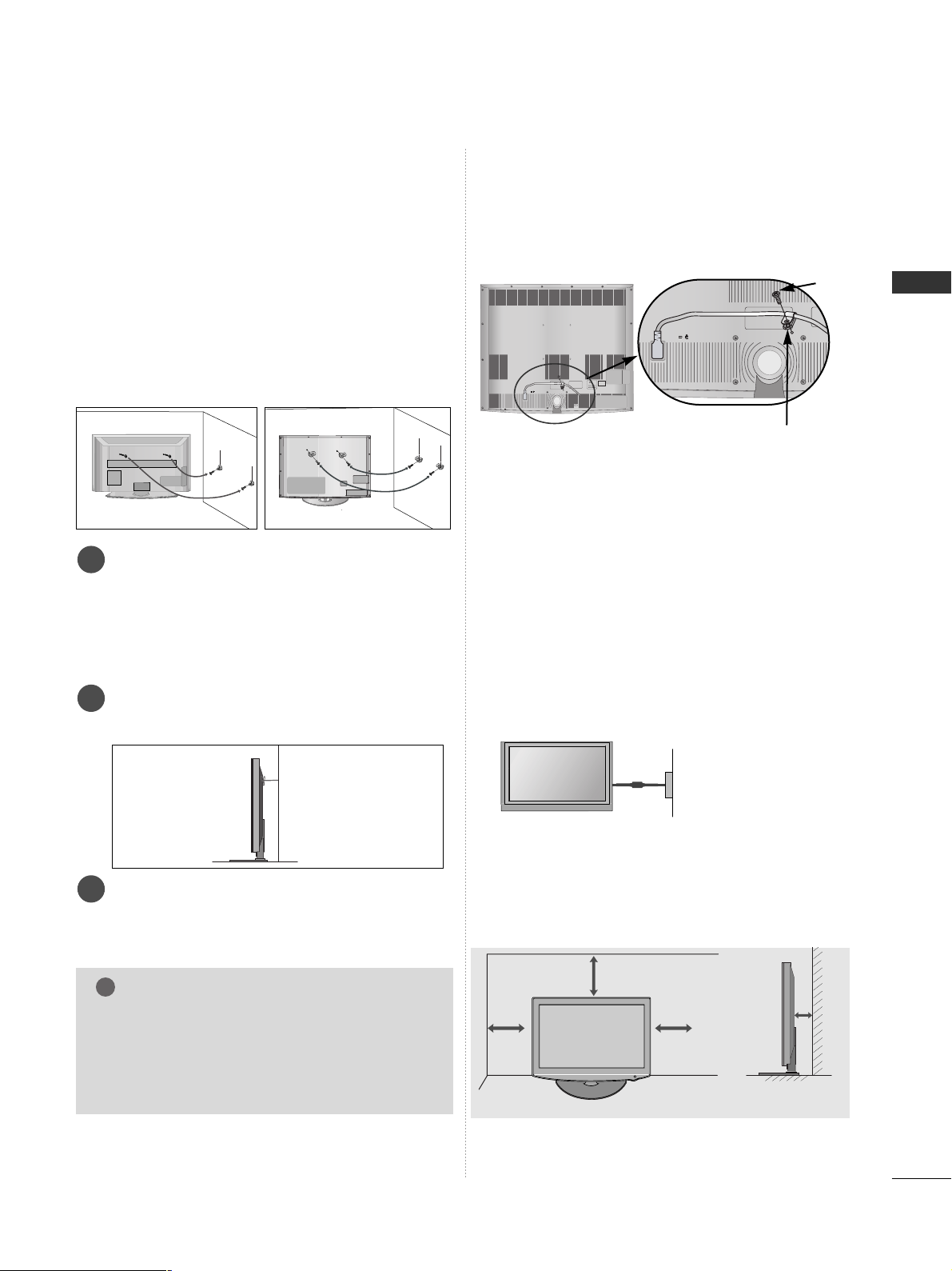
CAREFUL INSTALLATION ADVICE
A
You should purchase necessary components to fix the TV
safety and secure to the wall on the market.
A
Position the TV close to the wall to avoid the possibility
of it falling when pushed.
A
The instructions shown below are a safer way to set up
the TV, by fixing it to the wall, avoiding the possibility of
it falling forwards if pulled. This will prevent the TV from
falling forward and causing injury. This will also prevent
the TV from damage. Ensure that children do not climb
or hang from the TV.
NOTE
!
G
When moving the TV undo the cords first.
G
Use a platform or cabinet strong and large enough
to support the size and weight of the TV.
G
To use the TV safely make sure that the height of the
bracket on the wall and on the TV is the same.
3
1
2
Use the eye-bolts or TV brackets/bolts to fix the
product to the wall as shown in the picture.
(If your TV has bolts in the eyebolts, loosen then
bolts.)
* Insert the eye-bolts or TV brackets/bolts and tight-
en them securely in the upper holes.
Secure the wall brackets with the bolts on the wall.
Match the height of the bracket that is mounted on
the wall.
3
Use a sturdy rope to tie the product for alignment. It
is safer to tie the rope so it becomes horizontal
between the wall and the product.
2
1
2
1
How to secure the power cable
(Only 32/37/42/47LH7
***
)
PROTECTIVE BRACKET
Bolt
Secure the power cable with the PROTECTIVE BRACKET
and the bolt as shown. It will help prevent the power cable
from being removed by accident.
26
PREPARATION
PREPARATION
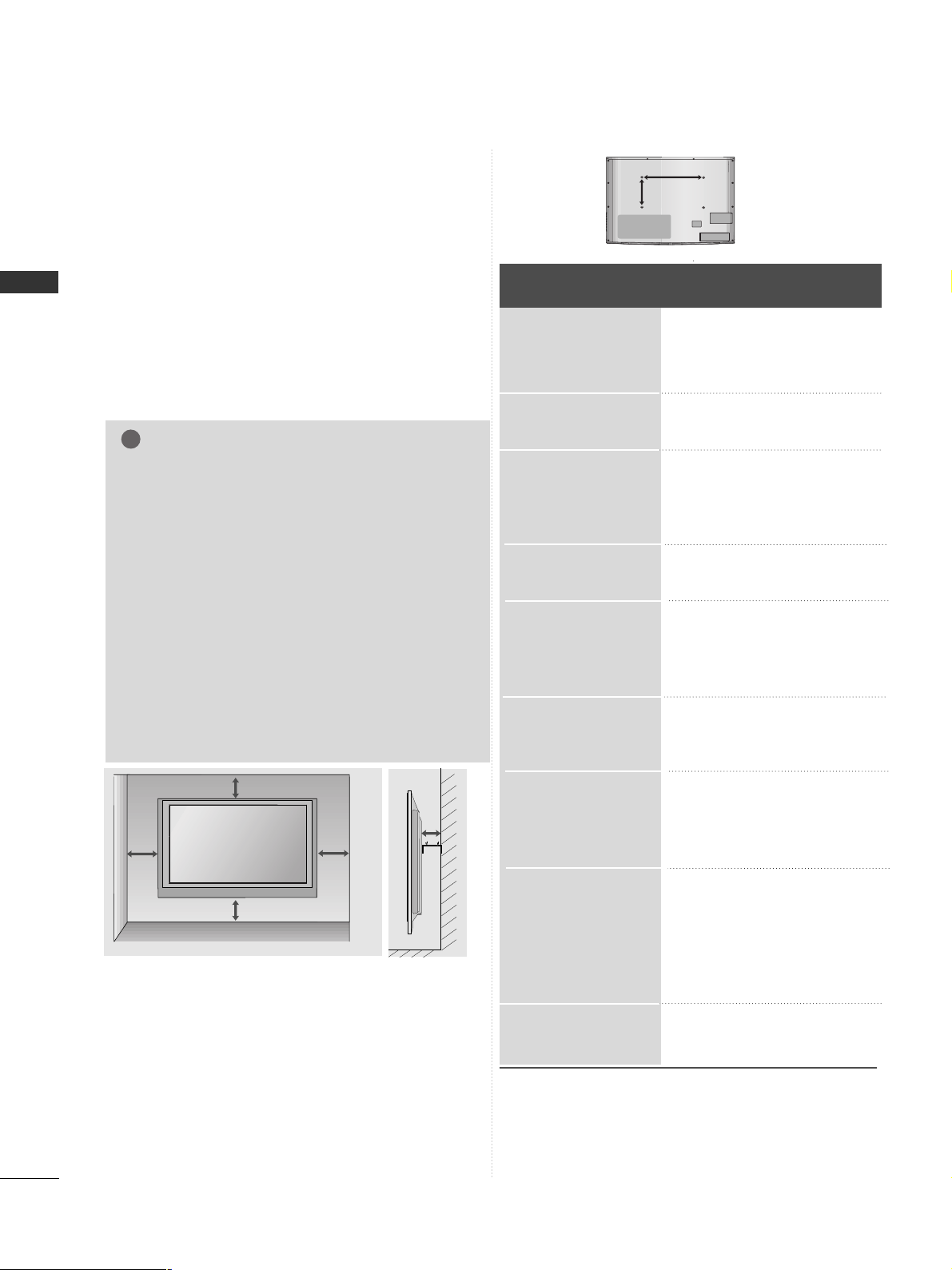
WALL MOUNT: HORIZONTAL INSTALLATION
A
We recommend the use of a LG Brand wall mounting
bracket when mounting the TV to a wall.
A
We recommend that you purchase a wall mounting
bracket which supports VESA standard.
A
LG recommends that wall mounting be performed
by a qualified professional installer.
A
First you connect the USB extension cable to the
USB IN terminal, and then hang it on the wall.(Only
32/37/42/47LH7***)
4 inches
4 inches
4 inches
4 inches
4 inches
NOTE
!
G Should Install wall mount on a solid wall perpendicular to
the floor.
G Should use a special wall mount, if you want to install it to
ceiling or slanted wall.
G The surface that wall mount is to be mounted on should
be of sufficient strength to support the weight of TV set;
e.g. concrete, natural rock, brick and hollow block.
G Installing screw type and length depends on the wall
mount used. Further information, refer to the instructions
included with the mount.
G LG is not liable for any accidents or damage to property or
TV due to incorrect installation:
- Where a non-compliant VESA wall mount is used.
- Incorrect fastening of screws to surface which may cause
TV to fall and cause personal injury.
- Not following the recommended Installation method.
Model
VESA
(A *B)
Standard
Screw
Quantity
55SL8***
47SL8***
42SL8***
32SL8***
47LH9***
42LH9***
47LH7***
42LH7***
37LH7***
32LH7***
42LH6***
32LH6***
55LH5***
47LH5***
42LH5***
37LH5***
26LU5***
22LU5***
19LU5***
47LH3***
42LH3***
37LH3***
32LH3***
42LH2***
37LH2***
32LH2***
26LH2***
22LH2***
19LH2***
42LF2***
32LF2***
400 * 400
200 * 200
200 * 200
200 * 10 0
200 * 200
200 * 200
200 * 200
200 * 200
200 * 200
200 * 10 0
200 * 200
200 * 10 0
400 * 400
200 * 200
200 * 200
200 * 200
200 * 10 0
100 * 10 0
100 * 10 0
200 * 200
200 * 200
200 * 200
200 * 10 0
200 * 200
200 * 200
200 * 10 0
200 * 10 0
100 * 10 0
100 * 10 0
200 * 200
200 * 10 0
M6
M6
M6
M4
M6
M6
M6
M6
M6
M4
M6
M4
M6
M6
M6
M6
M4
M4
M4
M6
M6
M6
M4
M6
M6
M4
M4
M4
M4
M6
M4
4
4
4
4
4
4
4
4
4
4
4
4
4
4
4
4
4
4
4
4
4
4
4
4
4
4
4
4
4
4
4
AA
BB
27
PREPARATION
ANTENNA
IN
ANTENNA
IN
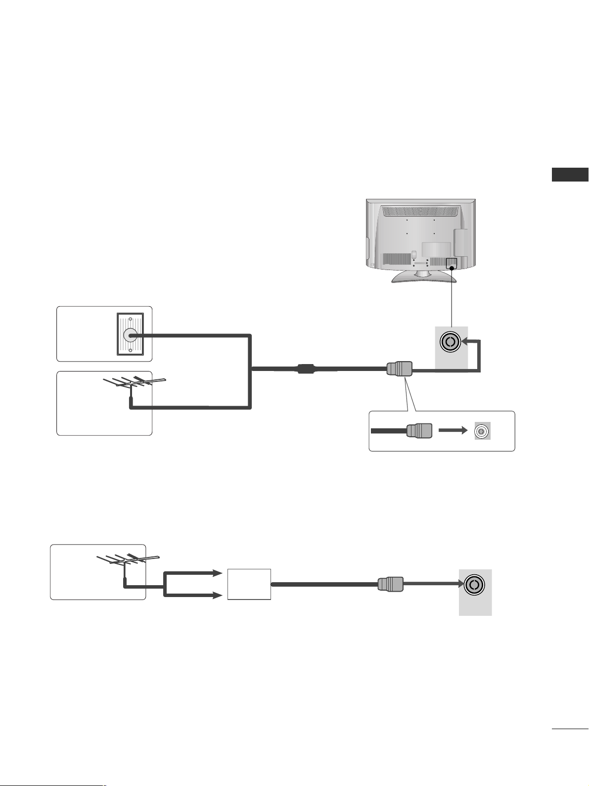
ANTENNA CONNECTION
■
For optimum picture quality, adjust antenna direction.
■
An antenna cable and converter are not supplied.
■
To prevent damage do not connect to the mains outlet until all connections are made between the devices.
Multi-family Dwellings/Apartments
(Connect to wall antenna socket)
Single-family Dwellings /Houses
(Connect to wall jack for outdoor antenna)
Outdoor
Antenna
(VHF, UHF)
Wall
Antenna
Socket
RF Coaxial Wire (75 ohm)
Antenna
UHF
Signal
Amplifier
VHF
■
In poor signal areas, to achieve better picture quality it may be necessary to install a signal amplifier to the
antenna as shown above.
■
If signal needs to be split for two TVs, use an antenna signal splitter for connection.
28
EXTERNAL EQUIPMENT SETUP
EXTERNAL EQUIPMENT SETUP
1
2
COMPONENT IN
AUDIO
VIDEO
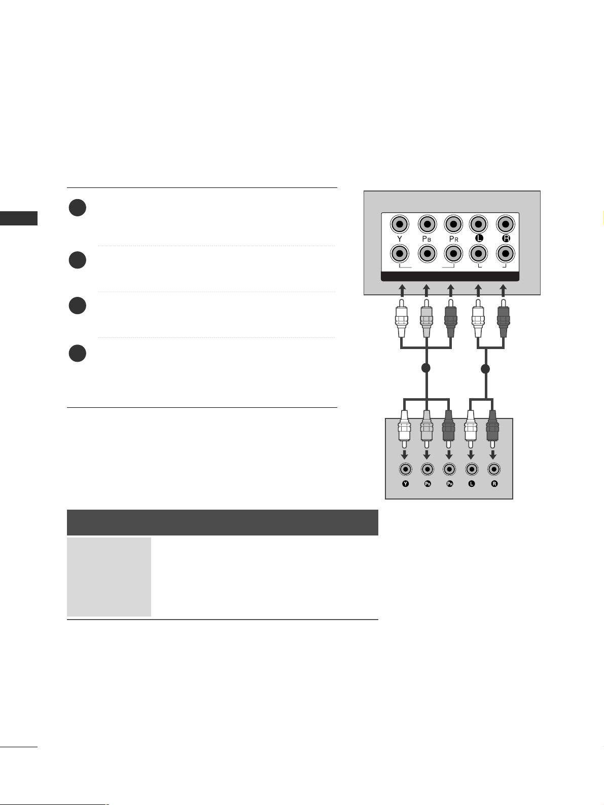
HD RECEIVER SETUP
■
To avoid damaging any equipment, never plug in any power cords until you have finished connecting all equipment.
■
This section on EXTERNAL EQUIPMENT SETUP mainly uses diagrams for the 37/42/47/55LH5*** models.
■
Here shown may be somewhat different from your TV.
Connecting with a component cable
1
2
Signal
480i/576i
480p/576p
720p/1080i
10 8 0 p
Component
O
O
O
O
(50/60Hz only)
HDMI
X
O
O
O
(24Hz/30Hz/50Hz/60Hz)
Connect the video outputs (Y, PB, PR
)
of the digital set
top box to the
CC OOMMPPOO NNEENNTT IINN VVIIDD EE OO
jacks on the
TV.
Connect the audio output of the digital set-top box to
the
CC OOMMPPOO NNEENNTT IINN AA UUDDIIOO
jacks on the TV.
Turn on the digital set-top box.
(
Refer to the owner’s manual for the digital set-top box.
)
Select
CC oo mm ppoonnee nntt11
input source using the
IINN PPUU TT
button on the remote control.
If connected to
CC OOMMPPOO NNEENN TT IINN 22
, select
CC oo mm ppoonnee nntt22
input source.
2
3
4
1
 Loading...