

Page 1

Please read this manual carefully before operating
your set.
Retain it for future reference.
Record model number and serial number of the set.
See the label attached on the back cover and quote
this information to your dealer
when you require service.
LCD TV
OWNER’S MANUAL
20LS7D
20LS7DC
23LS7D
23LS7DC
www.lgusa.com / www.lg.ca / www.lgcommercial.com
As an ENERGY STAR
Partner LGE U. S. A.,Inc.
has determined that this
product meets the
ENERGY STAR guidelines
for energy efficiency.
ENERGY STAR is a set of power-saving
guidelines issued by the U.S.
Environmental Protection Agency(EPA).
Page 2

Page 3
1
WARNING / CAUTION
WARNING / CAUTION
To prevent fire or shock hazards, do not expose
this product to rain or moisture.
FCC NOTICE
Class B digital device
This equipment has been tested and found to comply
with the limits for a Class B digital device, pursuant to
Part 15 of the FCC Rules. These limits are designed
to provide reasonable protection against harmful
interference in a residential installation. This equipment
generates, uses and can radiate radio frequency energy
and, if not installed and used in accordance with the
instructions, may cause harmful interference to radio
communications. However, there is no guarantee that
interference will not occur in a particular installation.
If this equipment does cause harmful interference to
radio or television reception, which can be determined
by turning the equipment off and on, the user is
encouraged to try to correct the interference by one
or more of the following measures:
- Reorient or relocate the receiving antenna.
- Increase the separation between the equipment and
receiver.
- Connect the equipment to an outlet on a circuit
different from that to which the receiver is connected.
- Consult the dealer or an experienced radio/TV
technician for help.
Any changes or modifications not expressly approved
by the party responsible for compliance could void
the user’s authority to operate the equipment.
CAUTION
Do not attempt to modify this product in any way
without written authorization from LG Electronics.
Unauthorized modification could void the user’s
authority to operate this product
The lightning flash with arrowhead
symbol, within an equilateral triangle, is
intended to alert the user to the presence
of uninsulated “dangerous voltage” within the
product’s enclosure that may be of sufficient
magnitude to constitute a risk of electric shock to
persons.
The exclamation point within an equilateral
triangle is intended to alert the user to
the presence of important operating and
maintenance (servicing) instructions in the literature accompanying the appliance.
TO REDUCE THE RISK OF ELECTRIC SHOCK
DO NOT REMOVE COVER (OR BACK). NO
USER SERVICEABLE PARTS INSIDE. REFER TO
QUALIFIED SERVICE PERSONNEL.
WARNING/CAUTION
TO REDUCE THE RISK OF FIRE AND ELECTRIC
SHOCK, DO NOT EXPOSE THIS PRODUCT TO
RAIN OR MOISTURE.
NOTE TO CABLE/TV INSTALLER
This reminder is provided to call the CATV system
installer’s attention to Article 820-40 of the National
Electric Code (U.S.A.). The code provides guidelines for
proper grounding and, in particular, specifies that the
cable ground shall be connected to the grounding system
of the building, as close to the point of the cable entry
as practical.
Page 4
2
IMPORTANT SAFETY INSTRUCTIONS
SAFETY INSTRUCTIONS
Important safety instructions shall be provided with each apparatus. This information shall be given in a separate
booklet or sheet, or be located before any operating instructions in an instruction for installation for use and
supplied with the apparatus.
This information shall be given in a language acceptable to the country where the apparatus is intended to be used.
The important safety instructions shall be entitled “Important Safety Instructions”. The following safety
instructions shall be included where applicable, and, when used, shall be verbatim as follows. Additional safety
information may be included by adding statements after the end of the following safety instruction list. At the
manufacturer’s option, a picture or drawing that illustrates the intent of a specific safety instruction may be
placed immediately adjacent to that safety instruction:
Read these instructions.
Keep these instructions.
Heed all warnings.
Follow all instructions.
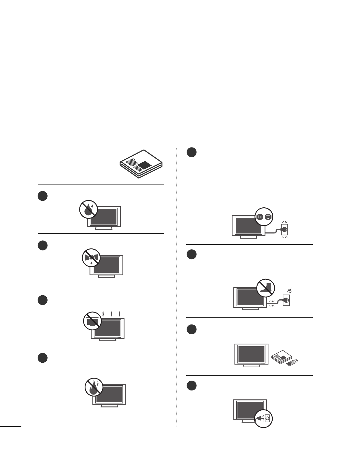
Do not use this apparatus near water.
Clean only with dry cloth.
Do not block any ventilation openings. Install in
accordance with the manufacturer’s instructions.
Do not install near any heat sources such as
radiators, heat registers, stoves, or other apparatus
(including amplifiers)that produce heat.
Do not defeat the safety purpose of the polarized
or grounding-type plug. A polarized plug has
two blades with one wider than the other. A
grounding type plug has two blades and a third
grounding prong, The wide blade or the third
prong are provided for your safety. If the provided
plug does not fit into your outlet, consult an
electrician for replacement of the obsolete outlet.
Protect the power cord from being walked on
or pinched particularly at plugs, convenience
receptacles, and the point where they exit from
the apparatus.
Only use attachments/accessories specified by
the manufacturer.
Unplug this apparatus when unused for long
periods of time.
1
2
3
4
5
6
7
8
Page 5
3
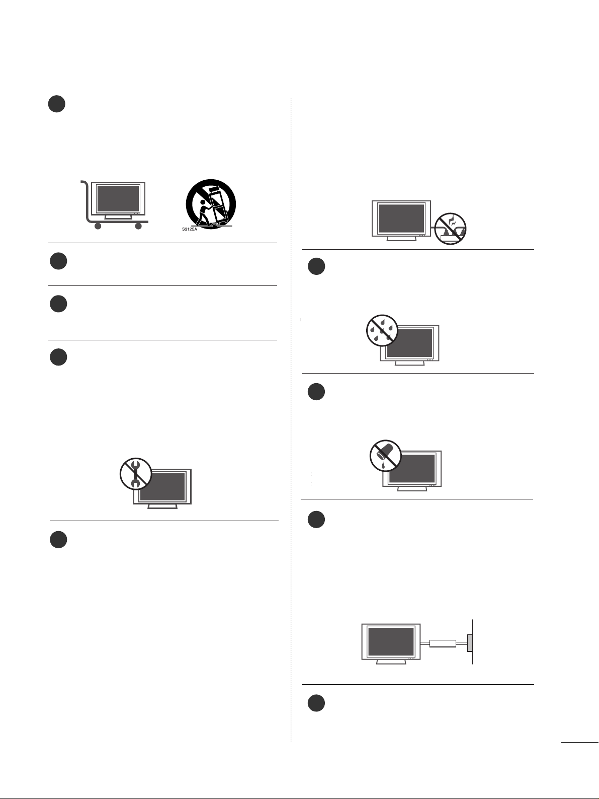
Use only with the cart, stand, tripod, bracket,
or table specified by the manufacturer, or sold
with the apparatus. When a cart is used, use
caution when moving the cart/apparatus
combination to avoid injury from tip-over.
Never touch this apparatus or antenna during
a thunder or lighting storm.
Do not allow a impact shock or any objects to
fall into the product, and do not drop onto the
screen with something.
Refer all servicing to qualified service personnel.
Servicing is required when the apparatus has
been damaged in any way, such as power-supply
cord or plug is damaged, liquid has been
spilled or objects have fallen into the apparatus,
the apparatus has exposed to rain or moisture,
does not operate normally, or has been
dropped.
CAUTION concerning the Power Cord :
Most appliances recommend they be placed
upon a dedicated circuit; that is, a single outlet
circuit which powers only that appliance and
has no additional outlets or branch circuits.
Check the specification page of this owner's
manual to be certain.
Do not overload wall outlets. Overloaded wall
outlets, loose or damaged wall outlets, extension
cords, frayed power cords, or damaged or
cracked wire insulation are dangerous. Any of
these conditions could result in electric shock
or fire. Periodically examine the cord of your
appliance, and if its appearance indicates damage or deterioration, unplug it, discontinue use
of the appliance, and have the cord replaced
with an exact replacement part by an authorized
servicer. Protect the power cord from physical
or mechanical abuse, such as being twisted,
kinked, pinched, closed in a door, or walked
upon. Pay particular attention to plugs, wall
outlets, and the point where the cord exits the
appliance.
Outdoor use marking :
WARNING - To reduce the risk of fire or elec-
tric shock, do not expose this appliance to rain
or moisture.
Wet Location Marking : Apparatus shall not be
exposed to dripping or splashing and no
objects filled with liquids, such as vases, shall
be placed on or over apparatus.
GGRROOUUNN DD IINNGG
Ensure that you connect the earth ground wire
to prevent possible electric shock. If grounding
methods are not possible, have a qualified
electrician install a separate circuit breaker.
Do not try to ground the unit by connecting it
to telephone wires, lightening rods, or gas pipes.
DDIISSCC OO NNNNEE CCTT II NNGG DDEEVVIICCEE FFRROOMM MMAAIINNSS
Mains plug is the disconnecting device. The
plug must remain readily operable.
9
12
10
11
13
14
15
16
17
Power
Supply
Short-circuit
Breaker
Page 6

4
CONTENTS
WARNING / CAUTION
. . . . . . . . . . . . . . . . . . . . . . . . . . . . 1
SAFETY INSTRUCTIONS
. . . . . . . . . . . . . . . . . . . . . . . . . . 2
INTRODUCTION
Feature of this TV
. . . . . . . . . . . . . . . . . . . . . . . . . . . . . . . . . . . . . . . . . . . . . 6
PREPARATION
Accessories
. . . . . . . . . . . . . . . . . . . . . . . . . . . . . . . . . . . . . . . . . . . . . . . . . . . . . .
7
Front Panel Information . . . . . . . . . . . . . . . . . . . . . . . . . . . . . . . . . . . . .8
Back Panel Information
. . . . . . . . . . . . . . . . . . . . . . . . . . . . . . . . . . . . . . 9
Stand Installation . . . . . . . . . . . . . . . . . . . . . . . . . . . . . . . . . . . . . . . . . . . .10
Detaching Stand
. . . . . . . . . . . . . . . . . . . . . . . . . . . . . . . . . . . . . . . . . . . . . .11
Back Cover for Wire Arrangement
. . . . . . . . . . . . . . . . . . . . . 12
Positioning your display
. . . . . . . . . . . . . . . . . . . . . . . . . . . . . . . . . . . 13
VESA Wall Mounting
. . . . . . . . . . . . . . . . . . . . . . . . . . . . . . . . . . . . . . . .
14
Desktop Pedestal Installation
. . . . . . . . . . . . . . . . . . . . . . . . . . . .14
Kensington Security System
. . . . . . . . . . . . . . . . . . . . . . . . . . . . . 15
Attaching the TV to a Desk
. . . . . . . . . . . . . . . . . . . . . . . . . . . . . . 15
Antenna or Cable Connection
. . . . . . . . . . . . . . . . . . . . . . . . . .
16
EXTERNAL EQUIPMENT SETUP
HD Receiver Setup
. . . . . . . . . . . . . . . . . . . . . . . . . . . . . . . . . . . . . . . . . 17
DVD Setup . . . . . . . . . . . . . . . . . . . . . . . . . . . . . . . . . . . . . . . . . . . . . . . . . . . . . 20
VCR Setup
. . . . . . . . . . . . . . . . . . . . . . . . . . . . . . . . . . . . . . . . . . . . . . . . . . . . .
22
Headphone Setup
. . . . . . . . . . . . . . . . . . . . . . . . . . . . . . . . . . . . . . . . . . .
24
PC Setup
. . . . . . . . . . . . . . . . . . . . . . . . . . . . . . . . . . . . . . . . . . . . . . . . . . . . . . . .25
WATCHING TV / CHANNEL CONTROL
Remote Control Functions
. . . . . . . . . . . . . . . . . . . . . . . . . . . . . . . 28
Turning On TV
. . . . . . . . . . . . . . . . . . . . . . . . . . . . . . . . . . . . . . . . . . . . . . . .
30
Channel Selection
. . . . . . . . . . . . . . . . . . . . . . . . . . . . . . . . . . . . . . . . . . .
30
Volume Adjustment
. . . . . . . . . . . . . . . . . . . . . . . . . . . . . . . . . . . . . . . . .
30
On-Screen Menus Selection
. . . . . . . . . . . . . . . . . . . . . . . . . . . . .
31
Channel Search
- Auto Scan (Auto Tuning)
. . . . . . . . . . . . . . . . . . . . . . . . . . . 32
- Add / Delete Channel (Manual Tuning)
. . . . . .
33
- Channel Editing
. . . . . . . . . . . . . . . . . . . . . . . . . . . . . . . . . . . . . . . .
34
Key Lock
. . . . . . . . . . . . . . . . . . . . . . . . . . . . . . . . . . . . . . . . . . . . . . . . . . . . . . . . . 35
PICTURE CONTROL
Picture Size (Aspect Ratio) Control . . . . . . . . . . . . . . . . . . 36
Preset Picture Settings
- Picture Mode - Preset
. . . . . . . . . . . . . . . . . . . . . . . . . . . . . . . 38
- Color Tone - Preset
. . . . . . . . . . . . . . . . . . . . . . . . . . . . . . . . . . .
39
Manual Picture Adjustment
- Picture Mode - User Mode
. . . . . . . . . . . . . . . . . . . . . . . . 40
- Color Tone - User Mode
. . . . . . . . . . . . . . . . . . . . . . . . . . .
41
XD (Picture Improvement Technology)
. . . . . . . . . . . . .
42
Advanced - Black (Darkness) Level
. . . . . . . . . . . . . . . . . . .43
Back Light
. . . . . . . . . . . . . . . . . . . . . . . . . . . . . . . . . . . . . . . . . . . . . . . . . . . . . . 44
Low-Power Picture Mode
. . . . . . . . . . . . . . . . . . . . . . . . . . . . . . . . .45
Picture Reset
. . . . . . . . . . . . . . . . . . . . . . . . . . . . . . . . . . . . . . . . . . . . . . . . . 46
SOUND & LANGUAGE CONTROL
Preset Sound Setting (Sound Mode)
. . . . . . . . . . . . . . . . 47
Sound Setting Adjustment - User Mode
. . . . . . . . . . . 48
Balance
. . . . . . . . . . . . . . . . . . . . . . . . . . . . . . . . . . . . . . . . . . . . . . . . . . . . . . . . . . 49
Stereo/SAP Broadcasts Setup
. . . . . . . . . . . . . . . . . . . . . . . . . . 50
Audio Language
. . . . . . . . . . . . . . . . . . . . . . . . . . . . . . . . . . . . . . . . . . . . . .51
On-Screen Menus Language Selection
. . . . . . . . . . . . . .
52
Caption Mode
. . . . . . . . . . . . . . . . . . . . . . . . . . . . . . . . . . . . . . . . . . . . . . . . 53
- Analog Broadcasting System Captions
. . . . . . . 54
- Digital Broadcasting System Captions
. . . . . . . .
55
- Caption Option
. . . . . . . . . . . . . . . . . . . . . . . . . . . . . . . . . . . . . . . .
56
Page 7

5
TIME SETTING
Clock Setting
- Auto Clock Setup
. . . . . . . . . . . . . . . . . . . . . . . . . . . . . . . . . . . . 57
- Manual Clock Setup
. . . . . . . . . . . . . . . . . . . . . . . . . . . . . . . . .
58
Auto On/Off Time Setting
. . . . . . . . . . . . . . . . . . . . . . . . . . . . . . 59
Sleep Time Setting
. . . . . . . . . . . . . . . . . . . . . . . . . . . . . . . . . . . . . . . . . .
60
Auto Shut-off Setting
. . . . . . . . . . . . . . . . . . . . . . . . . . . . . . . . . . . . . . . 61
PARENTAL CONTROL / RATINGS
Set Password & Lock System
. . . . . . . . . . . . . . . . . . . . . . . . . . .
62
Movie & TV Rating
. . . . . . . . . . . . . . . . . . . . . . . . . . . . . . . . . . . . . . . . . 64
APPENDIX
Troubleshooting
. . . . . . . . . . . . . . . . . . . . . . . . . . . . . . . . . . . . . . . . . . . . . .67
Maintenance
. . . . . . . . . . . . . . . . . . . . . . . . . . . . . . . . . . . . . . . . . . . . . . . . . . .
69
Product Specifications
. . . . . . . . . . . . . . . . . . . . . . . . . . . . . . . . . . . . .70
Page 8
6
FEATURE OF THIS TV
INTRODUCTION
If the TV feels cold to the touch, there may be a small “flicker” when it is turned on. This is normal, there is nothing wrong with TV.
Some minute dot defects may be visible on the screen, appearing as tiny red, green, or blue spots. However, they
have no adverse effect on the monitor's performance.
Avoid touching the LCD screen or holding your finger(s) against it for long periods of time. Doing so may produce
some temporary distortion effects on the screen.
On Disposal
a. The fluorescent lamp used in this product contains a small amount of mercury.
b. Do not dispose of this product with general household waste.
c. Disposal of this product must be carried out in accordance to the regulations of your local authority.
LG's own special digital image generator, consisting
of a full digital image processor, six different main
picture quality factors.
High-definition television. High-resolution digital
television broadcast and playback system composed
of roughly a million or more pixels, 16:9 aspect-ratio
screens, and AC3 digital audio. A subset of digital
television, HDTV formats include 1080i and 720p
resolutions.
Manufactured under license from Dolby Laboratories.
“
Dolby
“and the double-D symbol are trademarks of
Dolby Laboratories.
HDMITM, the HDMI logo and High-Definition
Multimedia Interface are trademarks or registered
trademarks of HDMI Licensing."
Page 9
PREPARATION
7
PREPARATION
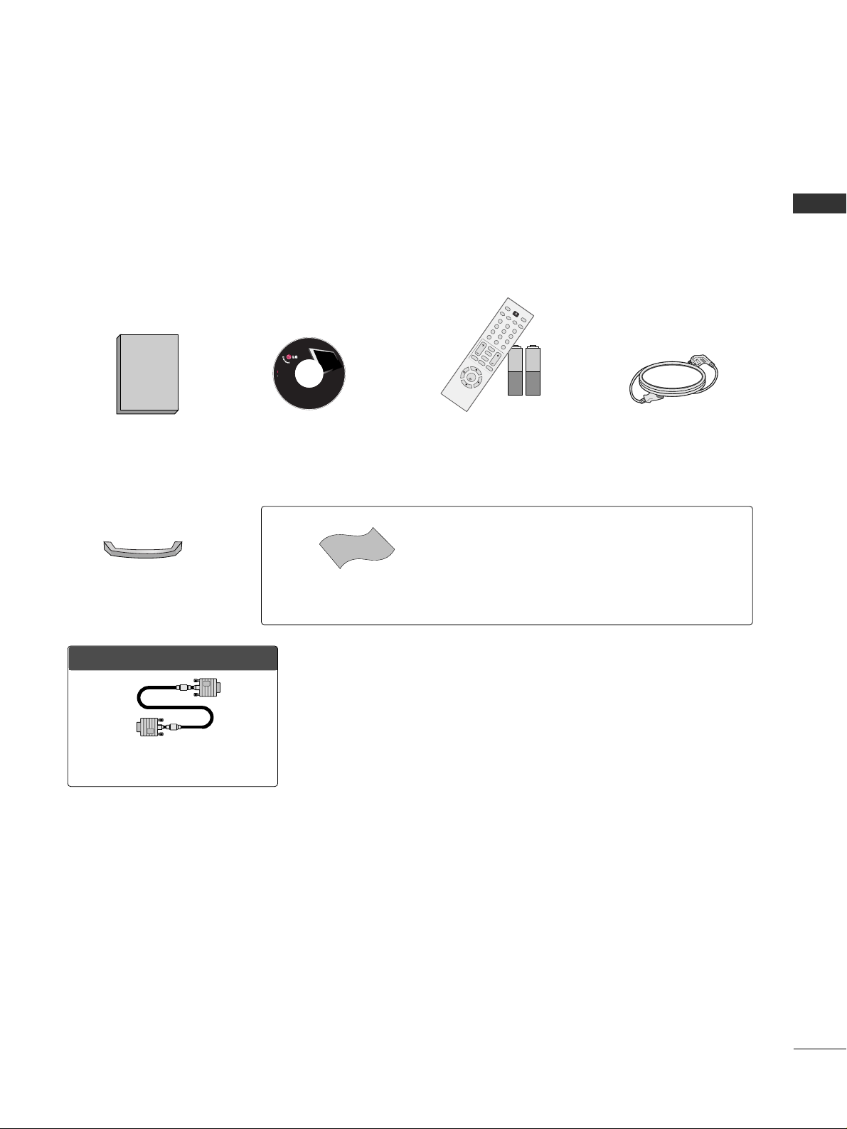
ACCESSORIES
Ensure that the following accessories are included with your product. If an accessory is missing, please contact
the dealer where you purchased the product.
User must use shielded signal interface cables (D-sub 15 pin cable) with ferrite cores to maintain standard
compliance for the product.
OOppttiioonn EExxttrraass
D-sub 15 pin Cable
1.5V 1.5V
Owner’s Manual CD Manual
123
456
78
0-
9
V
O
L
C
H
B
A
C
K
M
U
T
E
A
D
J
U
S
T
E
X
IT
C
C
F
A
V
S
O
U
N
D
T
I
M
E
R
N
P
U
T
123
456
78
0-
9
V
O
L
C
H
E
N
T
E
R
P
O
W
E
R
B
A
C
K
M
U
T
E
M
E
N
U
A
D
J
U
S
T
E
X
I
T
C
C
S
A
P
F
A
V
P
I
C
T
U
R
E
S
O
U
N
D
T
I
M
E
R
T
V
I
N
P
U
T
Remote Control,
Batteries
Power Cord
LCD TV
Owner's Manual
http://www.lgusa.com
www.lg.ca
Copyright© 2007 LGE,
All Rights Reserved.
Cable Management
* Slightly wipe stained spot on the exterior only with the polishing
cloth for the product exterior if there is stain or fingerprint on
surface of the exterior.
* Do not wipe roughly when removing stain. Please be cautions of
that excessive pressure may cause scratch or discoloration.
Polishing Cloth
Page 10
PREPARATION
8
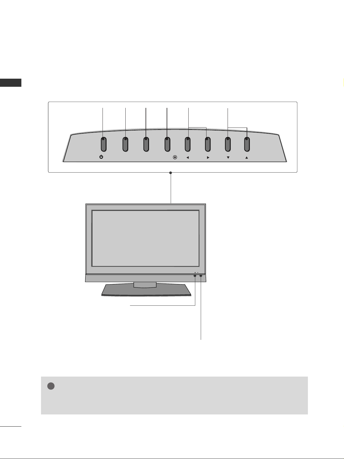
FRONT PANEL INFORMATION
PREPARATION
■
Here shown may be somewhat different from your TV.
Remote Control Sensor
Power/Standby Indicator
Illuminates red in standby mode.
Illuminates green when the set is switched on.
CHANNEL
(
EE,DD
)Buttons
VOLUME
(
FF,GG
)Buttons
MENU
Button
ENTER
Button
INPUT
Button
POWER
Button
GG
If your product has a protection tape attached, remove the tape.
And then wipe the product with a cloth (If a polishing cloth is included with your product, use it).
NOTE
!
/I
INPUT
MENU
ENTER
VOL CH
Page 11
PREPARATION
9
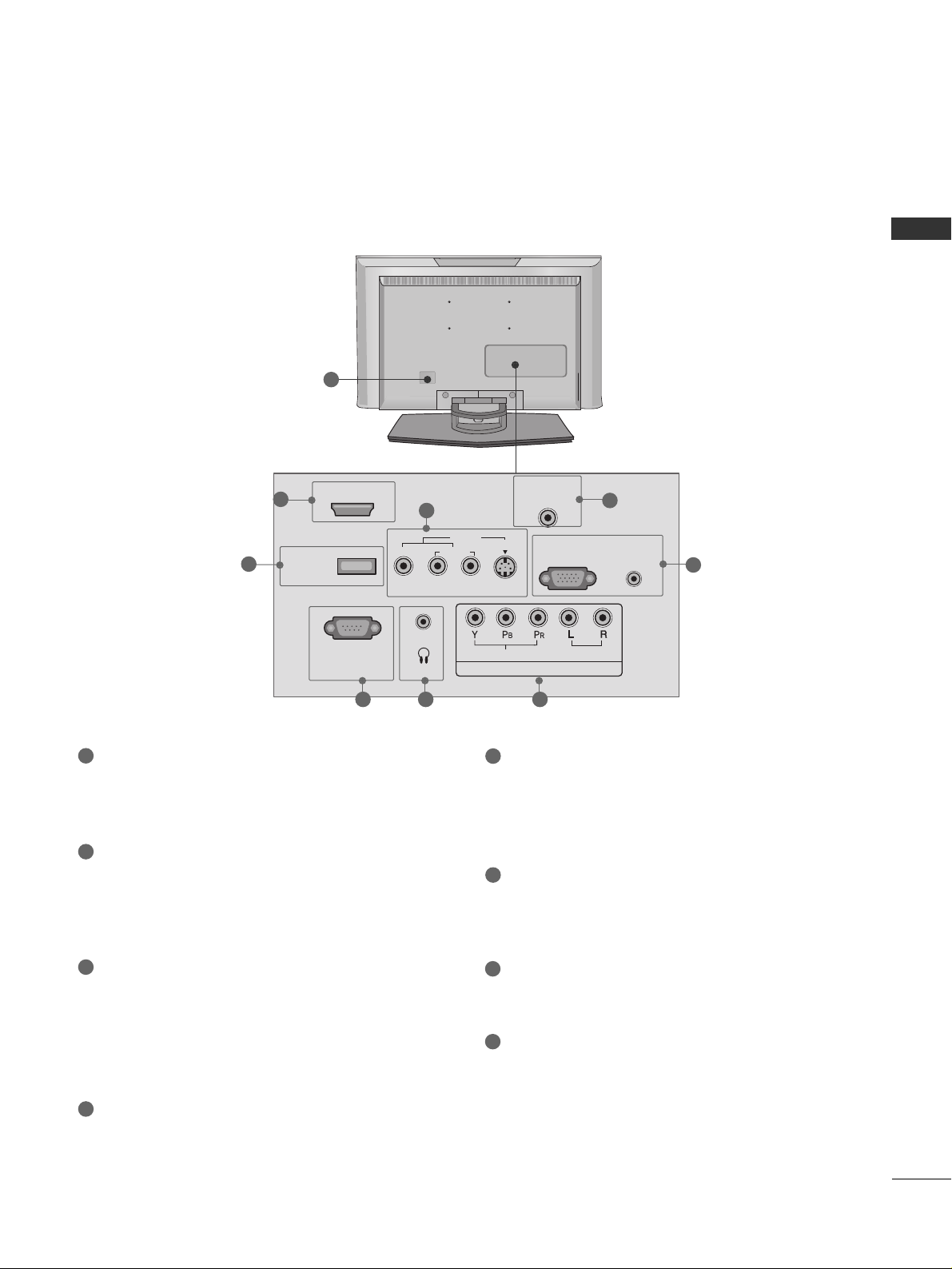
BACK PANEL INFORMATION
■
Here shown may be somewhat different from your TV.
SERVICE ONLY
RS-232C IN (SERVICE ONLY) PORT
For service.
HDMI/DVI IN
Connect a HDMI signal to this jack.
Or DVI (Video) signal to this jack with a HDMI to
DVI cable.
AV IN (Audio/Video)
Connect audio/video output from an external
device to these jacks.
S-VIDEO
Connect S-Video out from an S-VIDEO device.
ANTENNA/CABLE IN
Connect over-the air signals to this jack.
Connect cable signals to this jack.
RGB (PC) IN
Connect the output from a PC.
AUDIO (RGB/DVI) IN
Connect the audio from a PC or DTV.
COMPONENT IN
Connect a component video/audio device to
these jacks.
HEADPHONE INPUT
Plug the headphone into the headphone socket.
Power Cord Socket
For operation with AC power.
Caution: Never attempt to operate the TV on DC
power.
1
2
6
5
7
8
3
4
1 7 6
1
2
3
5
4
8
HDMI/DVI IN
VIDEO
SERVICE
ONLY
(SERVICE ONLY)
RS-232C IN
L
(MONO)
H/P
AV I N
AUDIO
ANTENNA/
S-VIDEO
R
VIDEO
COMPONENT IN
CABLE IN
RGB (PC) IN
AUDIO
AUDIO
(RGB/DVI)
IN
Page 12
PREPARATION
10
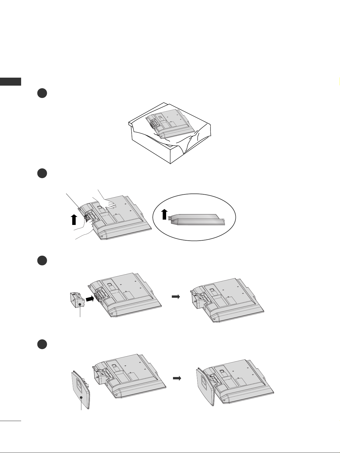
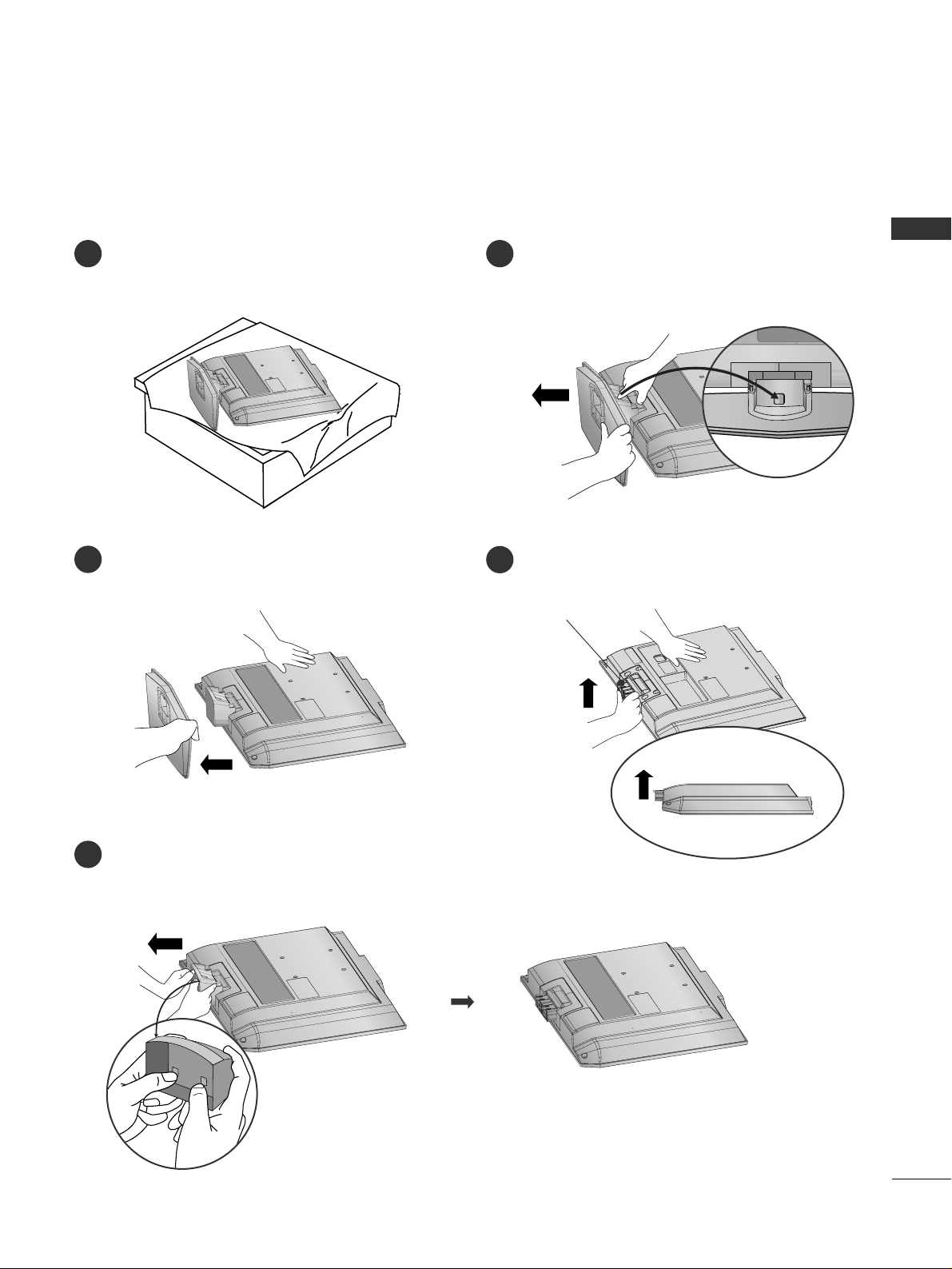
STAND INSTALLATION
PREPARATION
■
Here shown may be somewhat different from your TV.
Insert the
SS TTAANNDD BBOODDYY
into the product until clicking sound.
Carefully place the product screen side down on a cushioned surface that will protect product and screen
from damage.
Assemble the parts of the
SS TTAANNDD BBOODDYY
with
CCOOVVEERR BBAASS EE
of the product.
SS TTAANNDD BBOODDYY
3
1
4
Hold the
HHIINN GGEE BBOODDYY
and bend it upward.
2
HHIINN GGEE BBOODDYY
CCOOVVEERR BBAASS EE
Page 13
PREPARATION
11
DETACHING STAND
Carefully place the product screen side down on
a cushioned surface that will protect product and
screen from damage.
Pull cover base backward while pressing button
on stand body.
Shake the base while pulling, it will separate from
stand body.
Pull stand body to separate from set while pressing the 2 latches.
■
Here shown may be somewhat different from your TV.
1 2
4
3
5
Hold the
HHIINN GGEE BBOODDYY
and bend it upward.
HHIINN GGEE BBOODDYY
Page 14
PREPARATION
12
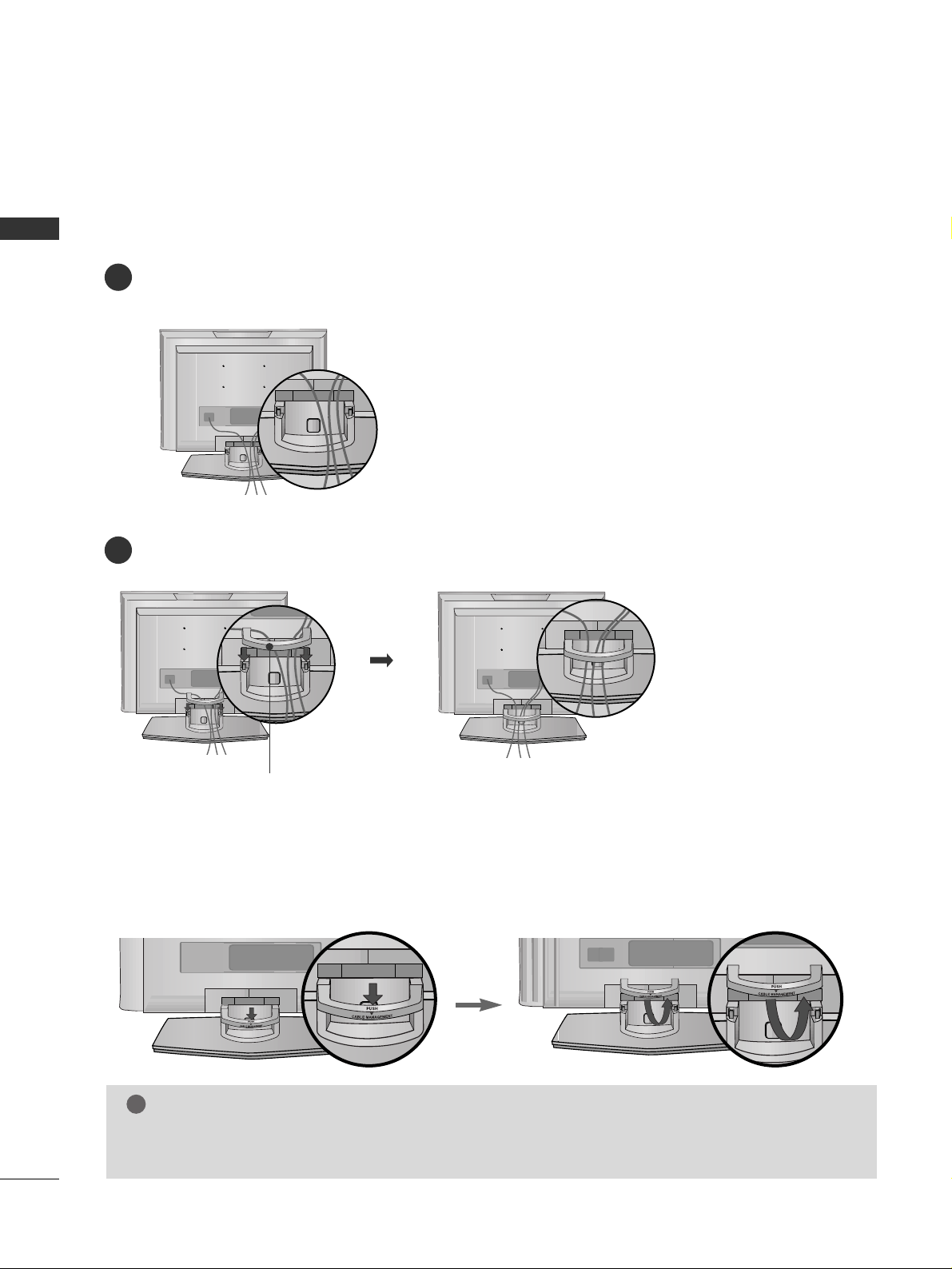
BACK COVER FOR WIRE ARRANGEMENT
PREPARATION
Connect the cables as necessary.
To connect an additional equipment, see the
EEXXTTEERRNNAALL EEQQUUIIPPMMEENNTT SSEETTUUPP
section.
Install the
CCAABBLLEE MMAANNAAGGEEMMEE NNTT
as shown.
First, press the cable management. Hold the
CCAABBLLEE MMAANNAAGGEEMMEE NNTT
with both hands and pull it upward.
NOTE
!
GG
Do not hold the
CCAABBLLEE MMAA NNAAGGEEMMEE NNTT
when moving the product.
- If the product is dropped, you may be injured or the product may be broken.
How to remove the CABLE MANAGEMENT
■
Here shown may be somewhat different from your TV.
1
2
CCAABBLLEE MMAANNAAGGEEMMEE NNTT
Page 15
PREPARATION
13
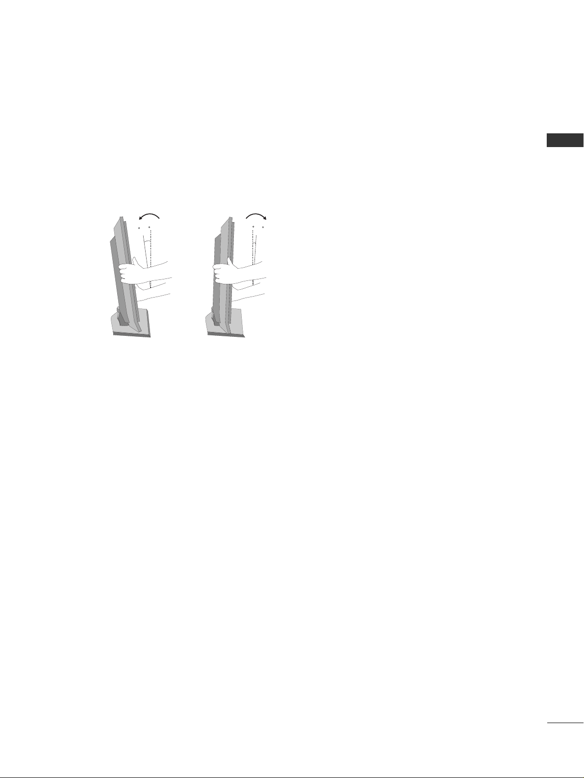
POSITIONING YOUR DISPLAY
■
Here shown may be somewhat different from your TV.
■
Adjust the position of the panel in various ways for maximum comfort.
• Tilt range
1
2~
1
0
3
0
Page 16
PREPARATION
14
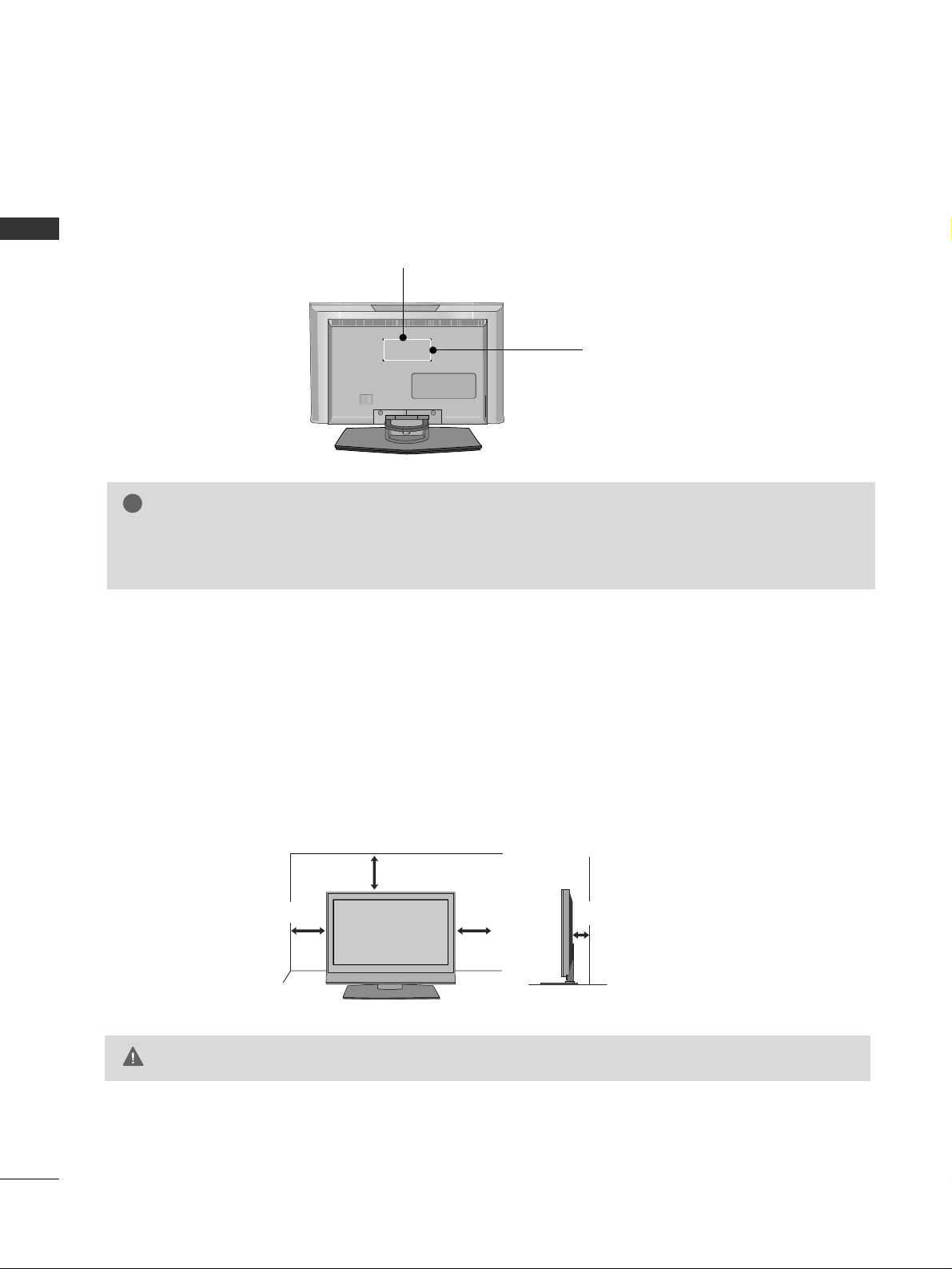
VESA WALL MOUNTING
PREPARATION
For proper ventilation, allow a clearance of 4 inches on all four sides from the wall.
GG
Ensure adequate ventilation by following the clearance recommendations.
CAUTION
DESKTOP PEDESTAL INSTALLATION
This product accepts a VESA-compliant mounting interface pad. (optional)
There 4 threaded holes are available for attaching the bracket.
GG
Screw length needed depends on the wall mount used. For further information, refer to the VESA
Wall Mounting Instruction Guide.
NOTE
!
100 mm
100 mm
4 inches
4 inches
4 inches
4 inches
Page 17
PREPARATION
15
KENSINGTON SECURITY SYSTEM
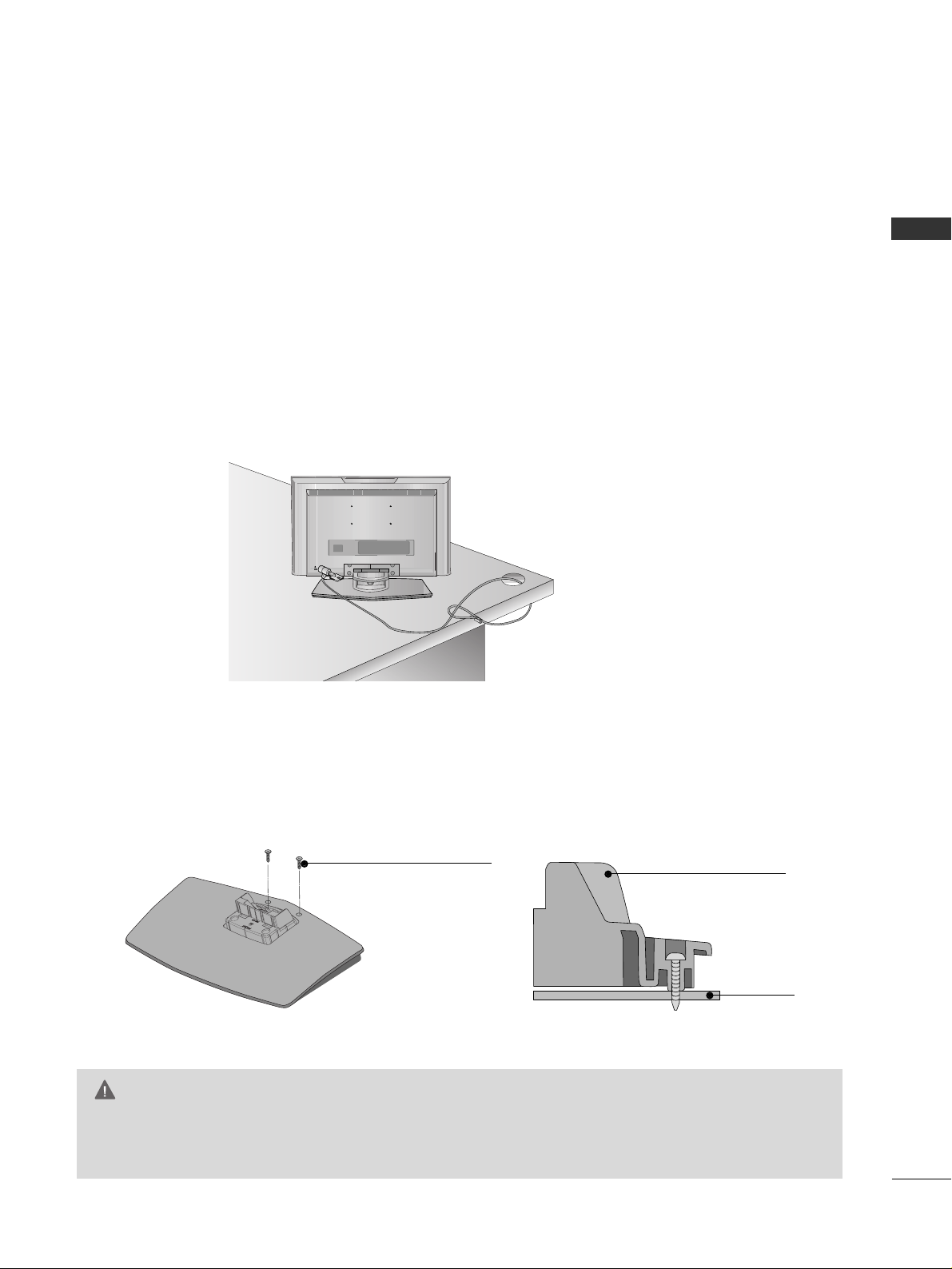
ATTACHING THE TV TO A DESK (Only 23 inches)
- The TV is equipped with a Kensington Security System connector on the back panel. Connect the
Kensington Security System cable as shown below.
- For the detailed installation and use of the Kensington Security System, refer to the user’s guide provided
with the Kensington Security System.
For further information, contact
hh ttttpp::// //ww wwww..kkeenn ssiinn ggttoonn..ccoomm
, the internet homepage of the
Kensington company. Kensington sells security systems for expensive electronic equipment such as notebook PCs and LCD projectors.
NOTE
- The Kensington Security System is an optional accessory.
The TV must be attached to a desk so it cannot be pulled in a forward/backward direction, potentially causing
injury or damaging the product.
GG
This apparatus must be securely attached to the floor/wall per installation instructions. Tipping, shaking, or rocking the machine may cause injury/death.
WARNING
Desk
Stand
2-Screws (M3x25)
(not provided as parts
of the product)
Page 18
PREPARATION
16
ANTENNA OR CABLE CONNECTION
PREPARATION
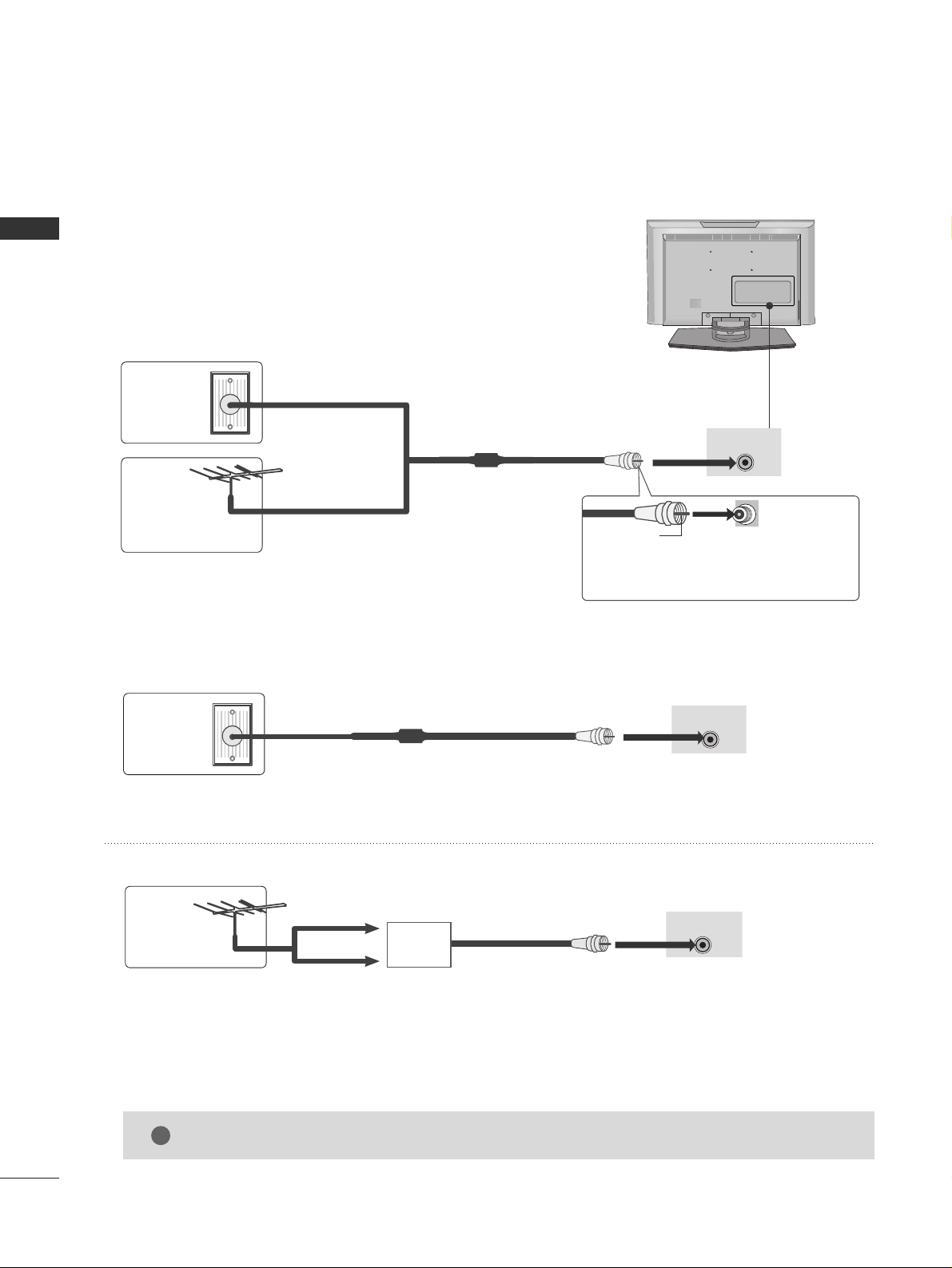
1. Antenna (Analog or Digital)
Wall Antenna Socket or Outdoor Antenna without a Cable Box
Connections.
For optimum picture quality, adjust antenna direction if needed.
2. Cable
Wa ll
Antenna
Socket
Outdoor
Antenna
(VHF, UHF)
Cable TV
Wall Jack
Multi-family Dwellings/Apartments
(Connect to wall antenna socket)
RF Coaxial Wire (75 ohm)
RF Coaxial Wire (75 ohm)
Single-family Dwellings /Houses
(Connect to wall jack for outdoor antenna)
Be careful not to bend the bronze wire
when connecting the antenna.
Copper Wire
ANTENNA/
CABLE IN
ANTENNA/
CABLE IN
ANTENNA/
CABLE IN
GG
The TV will let you know when the analog, cable, and digital channel scans are complete.
NOTE
!
■
To improve the picture quality in a poor signal area, please purchase a signal amplifier and install properly.
■
If the antenna needs to be split for two TV’s, install a 2-Way Signal Splitter.
■
If the antenna is not installed properly, contact your dealer for assistance.
Antenna
UHF
Signal
Amplifier
VHF
Page 19
EXTERNAL EQUIPMENT SETUP
17
HD RECEIVER SETUP
EXTERNAL EQUIPMENT SETUP
This TV can receive Digital Over-the-air/Cable signals without an external digital set-top box. However, if you
do receive digital signals from a digital set-top box or other digital external device, refer to the figure as shown
below.
■
To prevent the equipment damage, never plug in any power cords until you have finished connecting all equipment.
AUDIO
L
(MONO)
R
S-VIDEO
ANTENNA/
CABLE IN
RGB (PC) IN
AUDIO
(RGB/DVI)
IN
AV I N
H/P
VIDEO
AUDIO
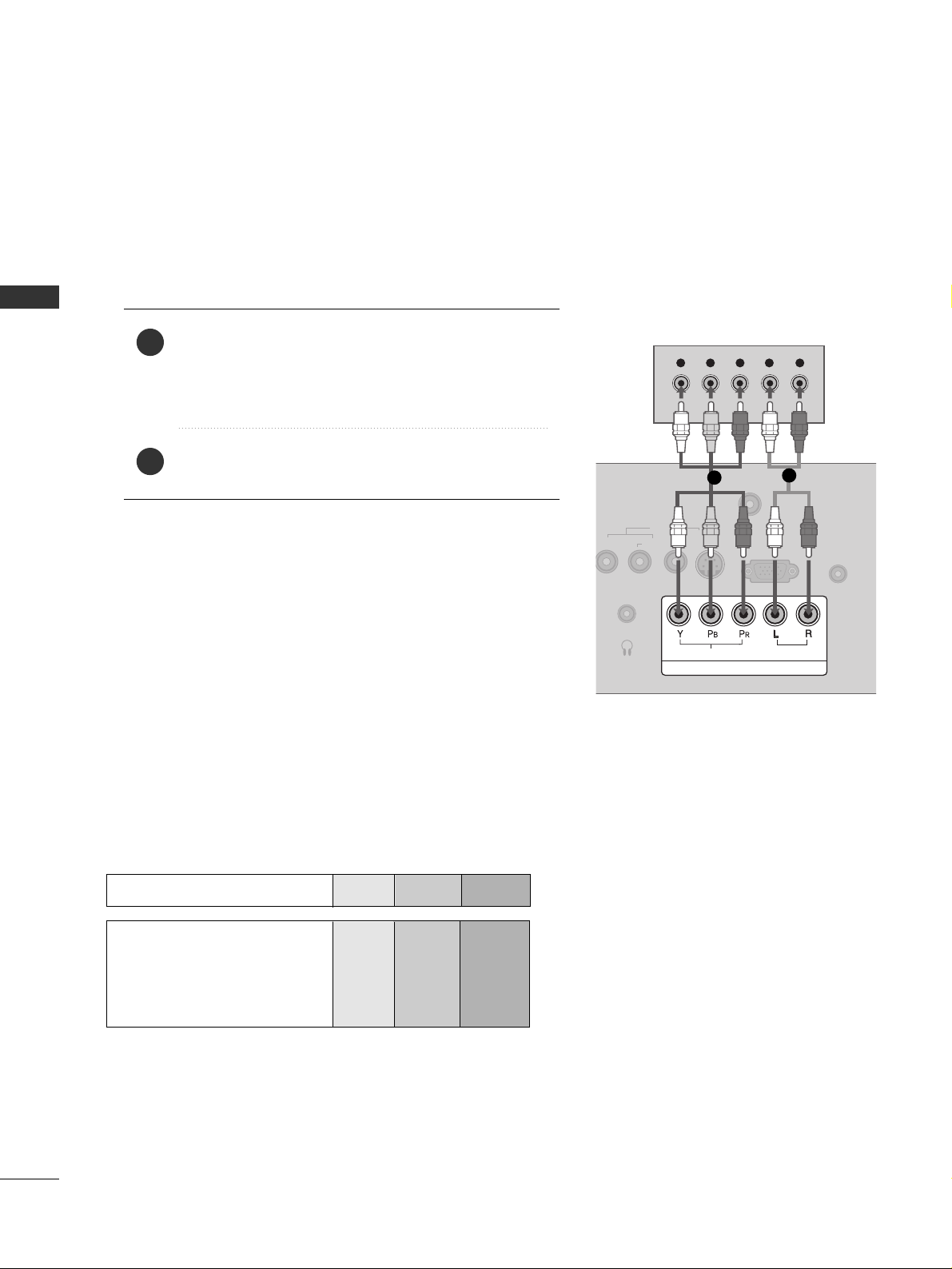
Y L RPB PR
COMPONENT IN
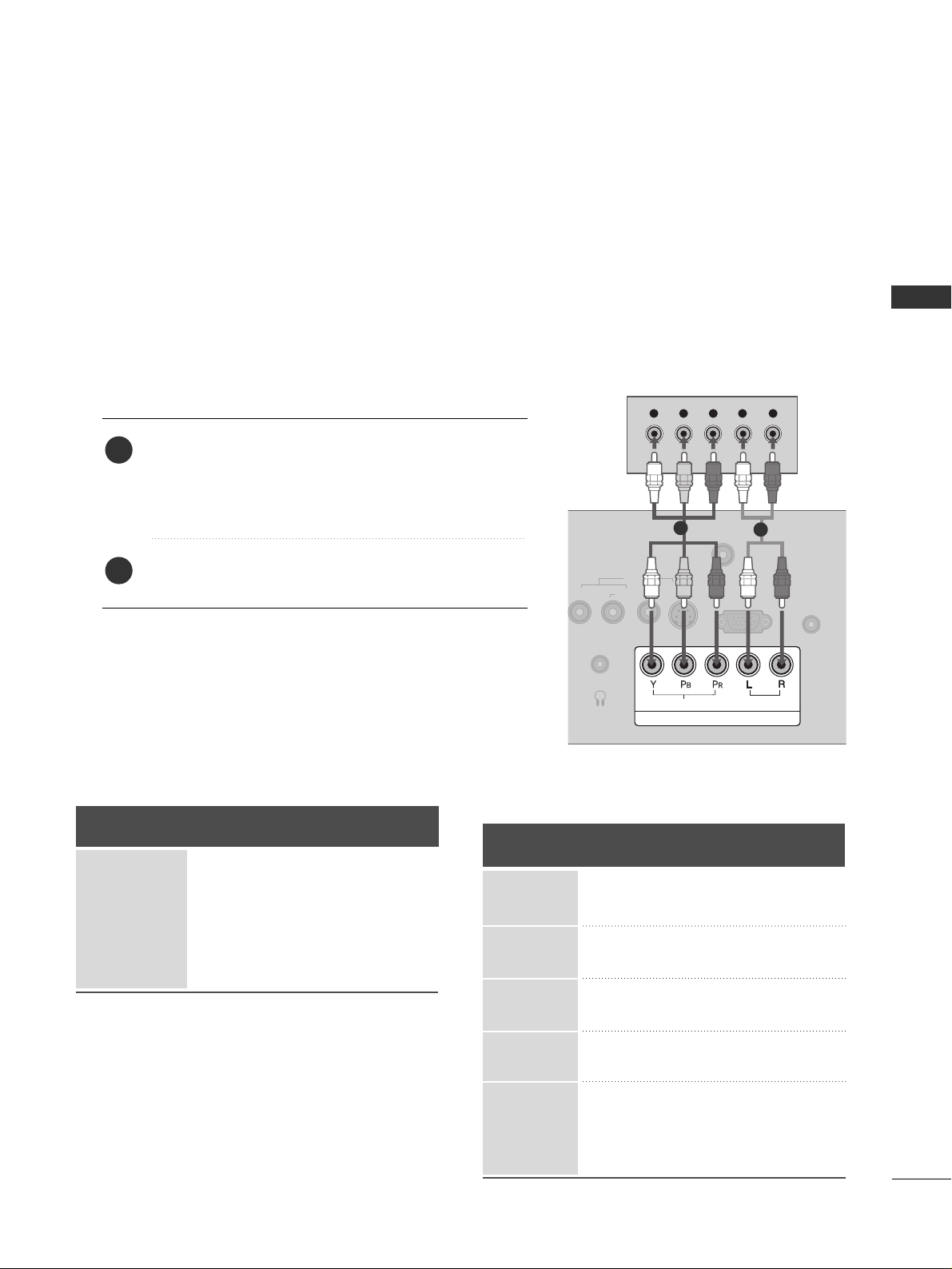
When connecting Component cable
1
2
1. How to connect
Connect the video outputs (Y, PB
, PR
)
of the digital set
top box to the
CCOOMMPPOONNEENN TT IINN VVIIDDEEOO
jacks on
the set. Match the jack colors
(Y = green, P
B
= blue, and PR = red).
Connect the audio output of the digital set-top box to
the
CCOOMMPPOONNEENN TT IINN AAUUDDIIOO
jacks on the set.
2
1
2. How to use
■
Turn on the digital set-top box.
(
Refer to the owner’s manual for the digital set-top box. operation
)
■
Select
CCoo mmppoo nn eenntt
input source by using the
IINNPP UU TT
button on the remote control.
Signal
480i
480p
720p
10 8 0 i
10 8 0 p
Component
Yes
Yes
Yes
Yes
Yes
HDMI
No
Yes
Yes
Yes
Yes
Y, C
B/
PB
, CR/
P
R
Horizontal Vertical
Frequency(KHz)Frequency(Hz
)
15.73 59.94
15.73 60.00
31.47 59.94
31.50 60.00
44.96 59.94
45.00 60.00
33.72 59.94
33.75 60.00
27.00 24.00
33.75 30.00
67.43 59.94
67.50 60.00
Resolution
720x480i
720x480p
1280x720p
1920x1080i
1920x1080p
Page 20
EXTERNAL EQUIPMENT SETUP
18
EXTERNAL EQUIPMENT SETUP
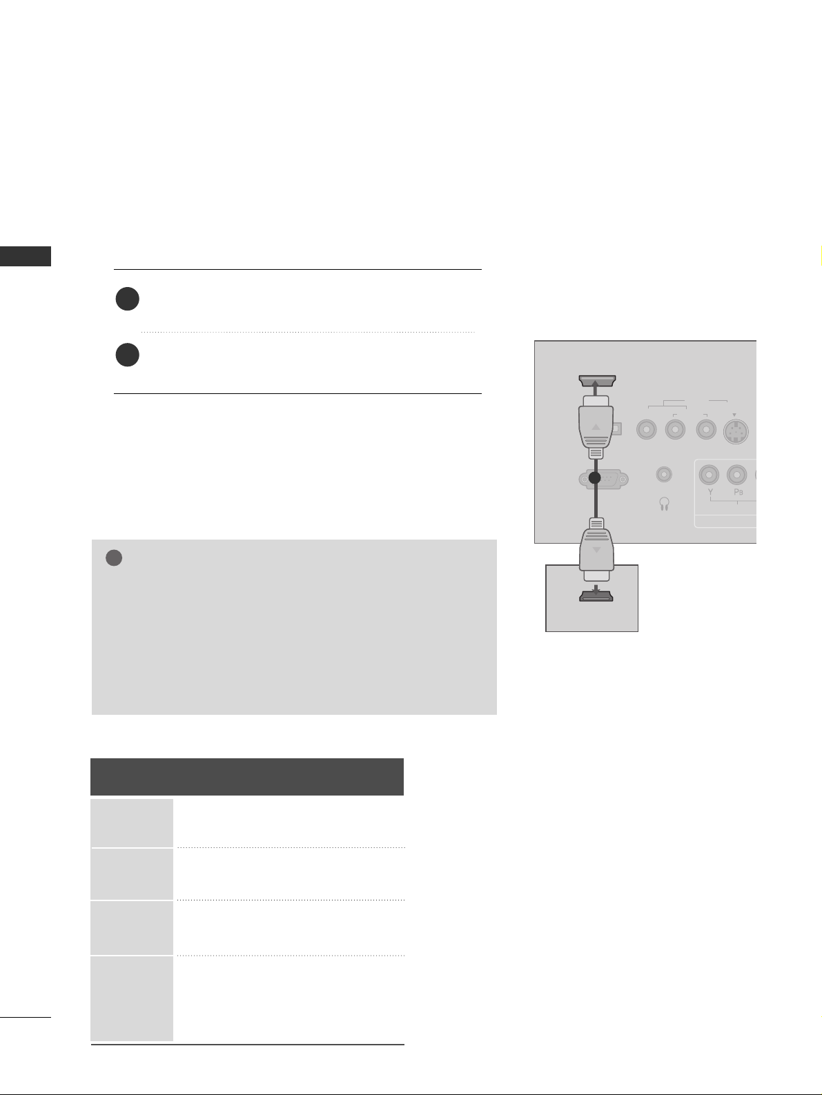
When connecting HDMI cable
Connect the digital set-top box to
HHDDMMII//DDVVII IINN
jack on the set.
No separated audio connection is necessary.
HDMI supports both audio and video.
1. How to connect
2. How to use
■
Turn on the digital set-top box.
(
Refer to the owner’s manual for the digital set-top box.
)
■
Select
HHDDMMII
input source by using the
IINNPPUU TT
button
on the remote control.
2
1
VIDEO
AUDIO
L
(MONO)
R
S-VIDEO
A
C
RS-232C IN
(SERVICE ONLY)
SERVICE
ONLY
HDMI/DVI IN
COMP
AV I N
H/P
VIDEO
HDMI-DTV OUTPUT
1
GG
When connected, the TV will tell a connected device what
resolution it supports and the resolution it prefers. If the
device supports this Auto HDMI function, the player output
resolution will be automatically set to 720p.
GG
If the device does not support Auto HDMI, you need to set
the output resolution appropriately.
NOTE
!
HDMI/DVI-DTV mode
Horizontal Vertical
Frequency(KHz)Frequency(Hz
)
31.469 59.94
31.500 60.00
44.96 59.94
45.00 60.00
33.72 59.94
33.75 60.00
27.00 24.00
33.75 30.00
67.43 59.94
67.50 60.00
Resolution
720x480p
1280x720p
1920x1080i
1920x1080p
Page 21

EXTERNAL EQUIPMENT SETUP
19
When connecting HDMI to DVI cable
VIDEO
AUDIO
L
(MONO)
R
S-VIDEO
ANTENNA/
CABLE IN
RS-232C IN
(SERVICE ONLY)
RGB (PC) IN
AUDIO
(RGB/DVI)
IN
SERVICE
ONLY
HDMI/DVI IN
COMPONENT IN
AV I N
H/P
VIDEO
AUDIO
L R
DVI-DTV OUTPUT
Connect the DVI output of the digital set-top box to the
HHDDMMII//DDVVII IINN
jack on the set.
Connect the audio output of the digital set-top box to the
AAUUDDIIOO
((
RRGGBB// DD VV II
))
IINN
jack on the set.
1. How to connect
■
Turn on the digital set-top box. (Refer to the owner’s manual for the digital set-top box.
)
■
Select
HHDDMM II
input source by using the
IINNPP UU TT
button on the remote control.
2. How to use
2
1
1
2
Page 22
EXTERNAL EQUIPMENT SETUP
20
DVD SETUP
EXTERNAL EQUIPMENT SETUP
When connecting Component cable
AUDIO
L
(MONO)
R
S-VIDEO
ANTENNA/
CABLE IN
RGB (PC) IN
AUDIO
(RGB/DVI)
IN
AV I N
H/P
COMPONENT IN
VIDEO
AUDIO
Y L RPB PR
Component Input ports
To get better picture quality, connect a DVD player to the component input ports as shown below.
Component ports on the TV
YPBP
R
Video output ports
on DVD player
Y
Y
Y
Y
P
B
B-Y
Cb
Pb
P
R
R-Y
Cr
Pr
Connect the video outputs (Y, P
B, P
R
)
of the DVD to the
CCOOMMPPOONNEENN TT IINN VVIIDDEEOO
jacks on the set.
Match the jack colors
(
Y = green, P
B = blue, and P
R = red
)
.
Connect the audio outputs of the DVD to the
CCOOMMPPOONNEENN TT IINN AAUUDDIIOO
jacks on the set.
1. How to connect
2. How to use
■
Turn on the DVD player, insert a DVD.
■
Select
CCoo mmppoo nn eenntt
input source by using the
IINNPP UU TT
button on the remote control.
■
Refer to the DVD player's manual for operating instructions.
2
1
1
2
Page 23
EXTERNAL EQUIPMENT SETUP
21
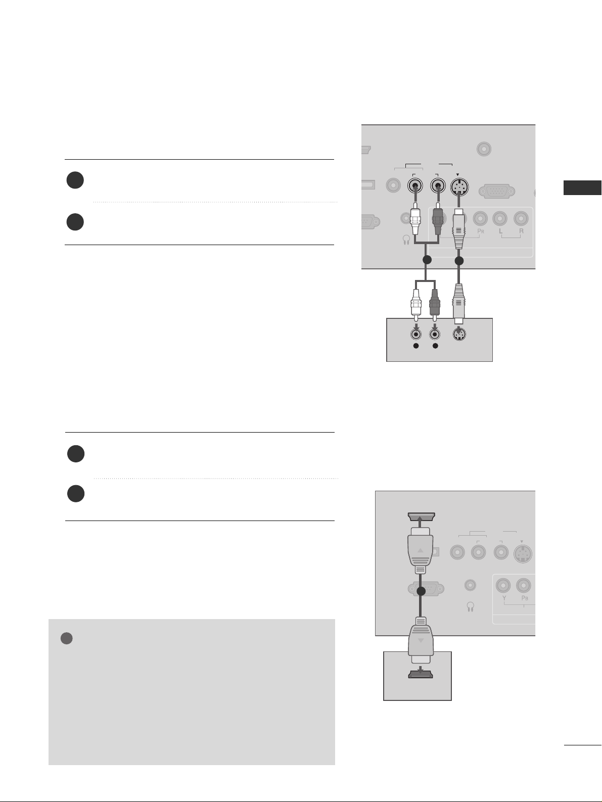
When connecting with an S-Video cable
VIDEO
AUDIO
L
(MONO)
R
S-VIDEO
ANTENNA/
CABLE IN
RGB (PC) IN
AU
(RG
VI IN
COMPONENT IN
AV I N
H/P
VIDEO
AUDIO
L R
S-VIDEO
AUDIO
R
1
2
Connect the S-VIDEO output of the DVD to the
SS --VV II DD EEOO
input on the set.
Connect the audio outputs of the DVD to the
AAUUDDIIOO
input jacks on the set.
1. How to connect
2. How to use
■
Turn on the DVD player, insert a DVD.
■
Select
AAVV
input source by using the
IINNPP UU TT
button on the
remote control.
■
Refer to the DVD player's manual for operating instructions.
2
1
VIDEO
AUDIO
L
(MONO)
R
S-VIDEO
A
C
RS-232C IN
(SERVICE ONLY)
SERVICE
ONLY
HDMI/DVI IN
COM
AV I N
H/P
VIDEO
HDMI-DVD OUTPUT
1
When connecting HDMI cable
Connect the HDMI output of the DVD to the
HHDDMMII//DDVVII IINN
jack on the set.
No separated audio connection is necessary.
HDMI supports both audio and video.
1. How to connect
2. How to use
■
Select
HHDDMMII
input source by using the
IINNPP UUTT
button
on the remote control.
■
Refer to the DVD player's manual for operating instructions.
2
1
GG
When connected, the TV will tell a connected device what
resolution it supports and the resolution it prefers. If the
device supports this Auto HDMI function, the player output resolution will be automatically set to 720p.
GG
If the device does not support Auto HDMI, you need to
set the output resolution appropriately.
To get the best picture quality, adjust the output resolution
of the DVD to 720p.
NOTE
!
Page 24
EXTERNAL EQUIPMENT SETUP
22
VCR SETUP
EXTERNAL EQUIPMENT SETUP
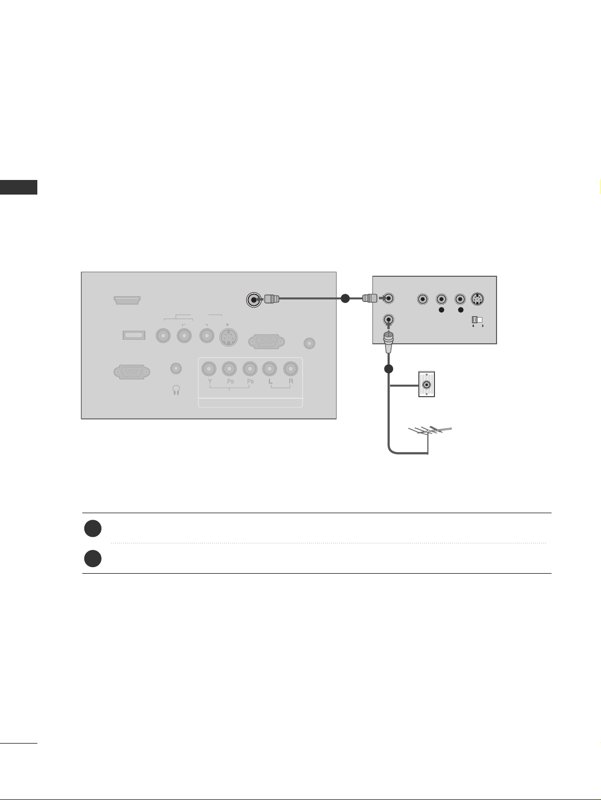
When connecting with an antenna
■
To avoid picture noise (interference), leave an adequate distance between the VCR and TV.
■
If the 4:3 picture format is used; the fixed images on the sides of the screen may remain visible on the
screen. This phenomenon is common to all manufactures and in consequence the manufactures warranty
does not cover the product bearing this phenomenon.
VIDEO
AUDIO
L
(MONO)
R
S-VIDEO
ANTENNA/
CABLE IN
RS-232C IN
(SERVICE ONLY)
RGB (PC) IN
AUDIO
(RGB/DVI)
IN
SERVICE
ONLY
HDMI/DVI IN
COMPONENT IN
AV I N
H/P
VIDEO
AUDIO
L R
S-VIDEOVIDEO
OUTPUT
SWITCH
ANT IN
ANT OUT
Wall Jack
Antenna
1
2
Connect the RF antenna out socket of the VCR to the
AANN TTEENNNNAA //CC AABBLLEE IINN
socket on the set.
Connect the antenna cable to the RF antenna in socket of the VCR.
1. How to connect
■
Set VCR output switch to 3 or 4 and then tune TV to the same channel number.
■
Insert a video tape into the VCR and press PLAY on the VCR. (Refer to the VCR owner’s manual.
)
2. How to use
2
1
Page 25
EXTERNAL EQUIPMENT SETUP
23
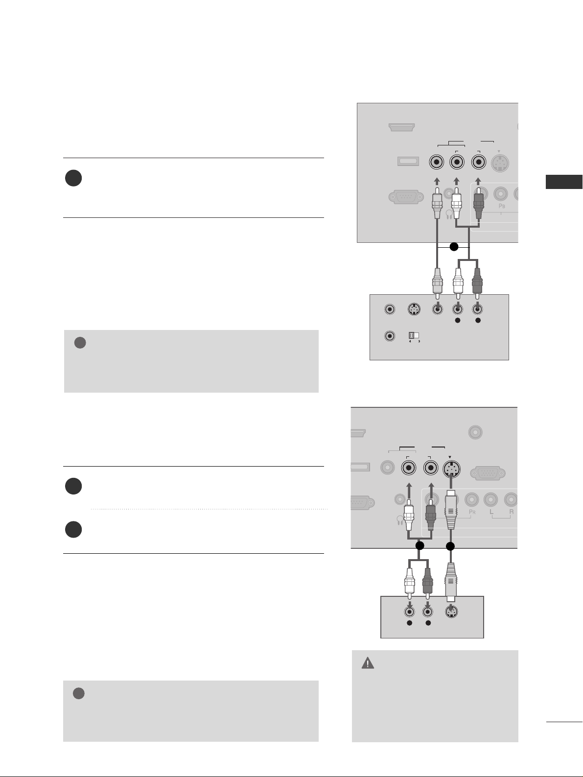
When connecting with a RCA cable
GG
Do not connect to both Video
and S-Video at the same time. In
the event that you connect both
Video and the S-Video cables,
only the S-Video will work.
CAUTION
GG
The picture quality is improved: compared to normal
composite (RCA cable) input.
NOTE
!
VIDEO
AUDIO
L
(MONO)
R
S-VIDEO
ANT
CA
RS-232C IN
(SERVICE ONLY)
SERVICE
ONLY
HDMI/DVI IN
COMPO
AV I N
H/P
VIDEO
L R
S-VIDEO VIDEO
OUTPUT
SWITCH
ANT IN
ANT OUT
VIDEO
AUDIO
L
(MONO)
R
S-VIDEO
ANTENNA/
CABLE IN
RGB (PC) IN
(
COMPONENT IN
AV IN
H/P
VIDEO
AUDIO
L R
S-VIDEO
AUDIO
Connect the
AAUUDDIIOO/VVIIDDEEOO
jacks between TV and
VCR. Match the jack colors (Video = yellow, Audio Left
= white, and Audio Right = red)
1. How to connect
2. How to use
■
Insert a video tape into the VCR and press PLAY on the
VCR. (Refer to the VCR owner’s manual.
)
■
Select
AAVV
input source by using the
IINNPP UU TT
button on the
remote control.
When connecting with an S-Video cable
Connect the S-VIDEO output of the VCR to the
SS --VV II DD EE OO
input on the set.
Connect the audio outputs of the VCR to the
AAUUDDIIOO
input jacks on the set.
1. How to connect
2. How to use
■
Insert a video tape into the VCR and press PLAY on the VCR.
(
Refer to the VCR owner’s manual.
)
■
Select
AAVV
input source by using the
IINNPP UU TT
button on the
remote control.
1
2
1
GG
If you have a mono VCR, connect the audio cable from
the VCR to the
AAUUDDII OO LL// MMOONN OO
jack of the set.
NOTE
!
1
1
2
Page 26

EXTERNAL EQUIPMENT SETUP
24
HEADPHONE SETUP
EXTERNAL EQUIPMENT SETUP
You can listen to the sound through the headphone.
Plug the headphone into the headphone socket.
To adjust the headphone volume, press the
VVOOLL
+ or
- button. If you press the
MM UUTTEE
button, the sound
from the headphone is switched off.
1. How to connect
2
1
VIDEO
A
L
(MON
RS-232C IN
(SERVICE ONLY)
SERVICE
ONLY
HDMI/DVI IN
H/P
Page 27

EXTERNAL EQUIPMENT SETUP
25
PC SETUP
This TV provides Plug and Play capability, meaning that the PC adjusts automatically to the TV's settings.
When connecting D-sub 15pin cable
AUDIO
(MONO)
R
S-VIDEO
RGB (PC) IN
AUDIO
(RGB/DVI)
IN
COMPONENT IN
AV I N
VIDEO
AUDIO
AUDIO
RGB OUTPUT
Connect the RGB output of the PC to the
RRGGBB
((
PP CC
))
II NN
jack on the set.
Connect the PC audio output to the
AAUUDDIIOO
((
RRGGBB// DD VV II
))
IINN
jack on the set.
1. How to connect
2. How to use
■
Turn on the PC and the TV.
■
Select
RRGGBB--PP CC
input source by using the
IINNPP UU TT
button
on the remote control.
2
1
1
2
When connecting HDMI to DVI cable
Connect the DVI output of the PC to the
HHDDMMII// DDVVII
II NN
jack on the set.
Connect the PC audio output to the
AAUU DD IIOO
((
RRGGBB// DD VV II))II NN
jack on the set.
1. How to connect
2. How to use
■
Turn on the PC and the TV.
■
Select
HHDDMM II
input source by using the
IINNPP UU TT
button on
the remote control.
2
1
VIDEO
AUDIO
L
(MONO)
R
RS-232C IN
(SERVICE ONLY)
SERVICE
ONLY
HDMI/DVI IN
AV I N
H/P
DVI-PC OUTPUT
AUDIO
AUDIO
(RGB/DVI)
IN
IO
1
2
Page 28

EXTERNAL EQUIPMENT SETUP
26
EXTERNAL EQUIPMENT SETUP
GG
To get the the best picture quality, adjust the PC
graphics card to 1366x768.
GG
Depending on the graphics card, DOS mode may
not work if a HDMI to DVI Cable is in use.
GG
If the video doesn’t fit the screen, try pressing the
ADJUST button to adjust the screen position of TV.
GG
Check the image on your TV. There may be noise
associated with the resolution, vertical pattern,
contrast or brightness in PC mode. If noise is
present, change the PC output to another resolution, change the refresh rate to another rate or
adjust the brightness and contrast on the PICTURE
menu until the picture is clear. If the refresh rate of
the PC graphic card can not be changed, change
the PC graphic card or consult the manufacturer of
the PC graphic card.
GG
Avoid keeping a fixed image on the screen for a
long period of time. The fixed image may become
permanently imprinted on the screen.
GG
The synchronization input form for Horizontal and
Vertical frequencies is separate.
NOTES
!
RGB-PC, HDMI/DVI-PC mode
Horizontal Vertical
Frequency(KHz)Frequency(Hz
)
31.469 70.08
31.469 70.08
31.469 59.94
37.879 60.31
48.363 60.00
47.776 59.87
47.712 60.01
47.720 59.799
47.13 59.65
Resolution
720x400
1360x768
RGB-PC
1360x768
HDMI-PC
640x480
800x600
1024x768
640x350
1280x768
1366x768
Supported Display Specifications
* RGB-PC mode only
Page 29

EXTERNAL EQUIPMENT SETUP
27
Screen Setup for PC mode
Overview
When the RGB input of the set is connected to a PC output, select
the RGB-PC as the main input mode.
After connecting RGB-PC to PC output and checking the screen quality.
When you change the resolution, select the proper resolution in present input to see the best picture appearance.
Adjustment for screen Resolution, Position, Size,
and Phase
Press the
AADDJJUUSSTT
button and then use
DD
or EEbutton to
select
RReess oolluuttiioo nn, PP ooss iitt iioonn, SS iizz ee
, or
PP hh aassee
.
Press the
EENNTTEERR
button and then use
DD EE FF GG
button to
make appropriate adjustments.
■
The
PPhhaassee
adjustment range is
00 ~++6633
.
■
The
SSiizzee
adjustment range is
--3300 ~++3300
.
Press the
EENNTTEERR
button.
Auto Configuration and Initializing
(Reset to original factory values)
Press the
AADDJJUUSSTT
button and then use
DD
or EEbutton to
select
AAuu ttoo.. CCoonn ffiigg..
or
RRee sseett
.
Press the
EENNTTEERR
button and then use
FF
or
GG
button to
select
YYee ss
.
Press the
EENNTTEERR
button.
0-
VOL
CH
BACK
MUTE
ADJUST
CC
FAV
MENU EXIT
1
2
3
1
2
3
1 2 3
1 2 3
Auto Config.
Resolution
Position
Size
Phase
Reset
Select
Prev
OK
DD
EE
ADJUST
1024 x 768
1280 x 768
1360 x 768
1366 x 768
Initialize Settings
Yes
No
Select
Prev
OK
FF GG
ADJUST
Auto Config.
Resolution
Position
Size
Phase
Reset
Start Auto configuration
Yes
No
Select
Prev
OK
FF GG
ADJUST
Auto Config.
Resolution
Position
Size
Phase
Reset
AAuuttoo CCoonnffiigg..
This function is to adjust picture
position and minimizes image shaking automatically.
RReessoolluuttiioonn
This function allows you select
resolution of XGA/WXGA.
PPoossiittiioonn
This function is to adjust picture to
left/right and up/down as you prefer.
SSiizzee
This function is to minimize any
vertical bars or stripes visible on
the screen background. And the
horizontal screen size will also
change.
PPhhaassee
This function allows you to remove
any horizontal noise and clear or
sharpen the image of characters.
RReesseett
This function is to initialize the
adjusted value.
Page 30

WATCHING TV / CHANNEL CONTROL
28
REMOTE CONTROL FUNCTIONS
WATCHING TV / CHANNEL CONTROL
When using the remote control, aim it at the remote control sensor on the TV.
123
456
780-9
VOL CH
ENTER
POWER
BACK
MUTE
MENU
ADJUST
EXIT
CC
SAP
FAV
PICTURE SOUND
TIMER
TV
INPUT
SAP
PICTURE
SOUND
TIMER
VOLUME UP
/DOWN
ADJUST
MUTE
CC
CHANNEL
UP/DOWN
MENU
BACK
EXIT
THUMBSTICK
(Up/Down/Left
Right/ENTER)
Analog mode: Selects MTS sound (Mono, Stereo, or a
SAP)
GG
pp..5500
DTV mode: Changes the audio language.
Selects the factory preset picture depend on the viewing
environment.
GG
pp..3388
Selects the factory preset sound for type of program.
GG
pp..4477
Select the amount of time before your TV turns off automatically.
GG
pp..6600
Increase/decrease the sound level.
Adjust the screen Auto config., Resolution, Position, Size
Phase and Reset.
GG
pp..2277
Switch the sound on or off.
GG
pp..3300
Select a closed caption.
GG
pp..5533
Select available channels.
Displays the main menu.
Tune to the last channel viewed.
Return to the previous menu.
Clear all on-screen displays and return to TV viewing from
any menu.
Navigate the on-screen menus and adjust the system settings to your preference.
Page 31

WATCHING TV / CHANNEL CONTROL
29
■
Open the battery compartment cover on the back
side and install the batteries matching correct
polarity (+ with +, - with -).
■
Install two 1.5V AAA batteries. Don’t mix old or
used batteries with new ones.
■
Close cover.
■
Use a remote control up to 7 meters distance
and 30 degree (left/right) within the receiving
unit scope.
■
Dispose of used batteries in a recycle bin to
preserve environment.
123
456
780-9
POWER
SAP
FAV
PICTURE SOUND
TIMER
TV
INPUT
Installing Batteries
Remote control effective range
NUMBER button
Turns your TV on or off.
In AV, Component, RGB-PC, and HDMI input sources, screen returns to the last TV channel.
External input modes rotate in regular sequence: TV, AV, Component, RGB-PC, and HDMI.
(AV, Component, RGB-PC, and HDMI input sources are linked automatically, only if a device
is connected.)
Used to enter a program number for multiple program channels such as 2-1, 2-2, etc.
Scroll through the programmed Favorite channels.
GG
pp..3344
POWER
TV
INPUT
— (DASH)
FAV
Page 32

WATCHING TV / CHANNEL CONTROL
30
TURNING ON TV
WATCHING TV / CHANNEL CONTROL
NOTE
!
GG
If you intend to be away on vacation, disconnect the power plug from the wall power outlet.
First, connect power cord correctly.
At this moment, the TV switches to standby mode.
■
In standby mode to turn TV on, press the ,
IINNPPUUTT,CCHH ((
DD
or
EE
))
button on the TV or press the
PPOOWWEERR, IINNPPUUTT, TTVV, CCHH ((
+ or -)),
NNuummbbeerr ((00~99))
button on the remote control.
Select the viewing source by using the
IINNPPUUTT
button on the remote con-
trol.
■
This TV is programmed to remember which power state it was last set
to, even if the power cord is out.
When finished using the TV, press the
PPOOWWEERR
button on the remote
control. The TV reverts to standby mode.
123
456
780-9
VOL
CH
POWER
BACK
MUTE
ADJUST
CC
SAP
FAV
MENU EXIT
PICTURE SOUND
TIMER
TV INPUT
1
2
3
123
456
780-9
VOL
CH
MUTE
ADJUST
CC
FAV
Press the
CCHH ((
+ or -))or
NNUUMMBBEERR
buttons to select a channel number.
1
VOLUME ADJUSTMENT
CHANNEL SELECTION
Press the
VVOOLL ((
+ or -))button to adjust the volume.
If you want to switch the sound off, press the
MMUUTTEE
button.
You can cancel the Mute function by pressing the
MMUUTTEE
or
VVOOLL ((
+ or -
))
button.
0-
VOL
CH
BACK
MUTE
ADJUST
CC
FAV
MENU EXIT
Adjust the volume to suit your personal preference.
1
2
3
Page 33

WATCHING TV / CHANNEL CONTROL
31
ON-SCREEN MENUS SELECTION
Press the
MMEENNUU
button and then use
DD
or
EE
button to select the each menu.
Press the
GG
button and then use
DD EE FF GG
button to display the available menus.
Your TV's OSD (On Screen Display)may differ slightly from what is shown in this manual.
2
1
SETUP
PICTURE
TIME
AUDIO
Sound Mode : Standard
Balance : 0
Clock :
- - - -, - - - -, - - : - - - -
Off Time : Off
On Time : Off
Sleep Time : Off
Auto Sleep : Off
Language : English
Key Lock : Off
Caption : Off
Low Power : Off
OPTION
Auto Tuning
Manual Tuning
Channel Edit
Picture Mode : User
Color Temperature : Cool
XD
Advanced
Aspect Ratio : 16:9
Back Light : 100
Picture Reset
LOCK
Lock System : Off
Set Password
Movie Rating
TV Rating-Children
TV Rating-General
Downloadable Rating
Lock System : Off
Set Password
TV Rating-English
TV Rating-French
Downloadable Rating
For USA
For Canada
Page 34

WATCHING TV / CHANNEL CONTROL
32
CHANNEL SEARCH
WATCHING TV / CHANNEL CONTROL
Press the
MM EENNUU
button and then use
DD
or
EE
button
to select the
SS EETTUUPP
menu.
Press the
GG
button and then use
DD
or
EE
button to
select
AAuu ttoo TTuunn iinn gg
.
Press the
EENNTTEE RR
button to begin the channel search.
Allow
AAuu ttoo TTuunn iinn gg
to complete the channel search
cycle for
AANN TTEENNNNAA
and
CC AABBLLEE
.
Automatically finds all channels available through antenna
or cable inputs, and stores them in memory on the channel
list.
Run Auto Tuning again after any Antenna/Cable connection
changes.
A password is required to gain access to Auto Tuning menu
if the Lock System is turned on.
2
3
1
ENTER
BACK
CC
MENU EXIT
Auto Scan (Auto Tuning)
1
2
3
Auto Tuning
Manual Tuning
Channel Edit
Auto Tuning
G
Manual Tuning
Channel Edit
Selection ( Gor )
leads you to the
Auto Tuning screen.
Auto Tuning
Manual Tuning
Channel Edit
Selection ( Gor )
leads you to the
Auto Tuning screen.
Processing Auto Tuning...
DTV Ch. 23
Found Channel(s) : 16
Press to stop the
current scan and start
TV channel scan.
BACK Prev
Next
Page 35

WATCHING TV / CHANNEL CONTROL
33
A password is required to gain access to Manual Tuning
menu if the Lock System is turned on.
If selecting DTV or CADTV input signal, you can view the
on-screen signal strength monitor to see the quality of the
signal being received.
Press the
MM EENNUU
button and then use
DD
or
EE
button
to select the
SS EETTUUPP
menu.
Press the
GG
button and then use
DD
or
EE
button to
select
MM aannuuaall TTuunniinngg
.
Press the
GG
button and then use
DD
or
EE
button to
select
TT VV, DDTTVV, CC AATTVV
, and
CC AADDTTVV
.
Press the
GG
button and then use
DD
or
EE
button to
select channel you want to add or delete.
Press the
EENNTTEE RR
button to add or delete the channel.
Press the
EEXXIITT
button to return to TV viewing or press
the
BBAACC KK
button to return to the previous menu.
ENTER
BACK
CC
MENU EXIT
2
1
4
3
6
5
Add/Delete Channel (Manual Tuning)
1
2
3 4 5
Auto Tuning
Manual Tuning
G
Channel Edit
Select channel type
and RF-Channel number
DTV 2
Auto Tuning
Manual Tuning
Channel Edit
Select channel type
and RF-Channel number
DTV
GG
12
Press to
delete the channel.
DTV 12-0
DD
EE
Bad Normal Good
Auto Tuning
Manual Tuning
Channel Edit
Page 36

WATCHING TV / CHANNEL CONTROL
34
WATCHING TV / CHANNEL CONTROL
There are two different ways in order to add or delete
scanned channels. One is "Custom List" and the other is
"Favorite List" in the channel list. Both of them are available
after Auto Tuning on the SETUP menu.
A Custom List can be created by toggling each channel on
or off with ENTER button.
You can create your own Favorite List. Use the
FF AAVV
button
on the remote control when a channel is highlighted and
then add or delete the channel to/from your Favorite List.
Press the
MMEENNUU
button and then use
DD
or
EE
button
to select the
SSEETTUUPP
menu.
Press the
GG
button and then use
DD
or
EE
button to
select
CChhaann nn eell EEddii tt
.
Press the
GG
button and then use
DD
or
EE
button to
select
TT VV, DDTTVV, CC AATTVV
, and
CC AADDTTVV
.
Press the
GG
button and then use
DD
or
EE
button to
select channel and then use the
EENNTTEERR
button to add
or delete it.
Press
FFAAVV
button to add the channel to the Favorite List.
The surfing icon will appear in back of that channel
number.
Press the
EEXXIITT
button to return to TV viewing or press
the
BBAACC KK
button to return to the previous menu.
0-
VOL
CH
ENTER
BACK
MUTE
ADJUST
CC
FAV
MENU EXIT
2
1
3
4
5
Channel Editing
1
2
3 4
Auto Tuning
Manual Tuning
Channel Edit
Auto Tuning
Manual Tuning
Channel Edit
G
TV
2-0
4-0
6-0
9-0
11-0
13-0
14-0
Add/Delete
Favorite
FAV
Auto Tuning
Manual Tuning
Channel Edit
DD
EE
G
TV
Add/Delete
Favorite
FAV
2-0
4-0
6-0
9-0
11-0
13-0
14-0
Page 37

WATCHING TV / CHANNEL CONTROL
35
KEY LOCK
ENTER
BACK
CC
MENU EXIT
The TV can be set up so that it can only be used with the
remote control.
This feature can be used to prevent unauthorized viewing
by locking out the front panel controls.
This TV is programmed to remember which option it was
last set to even if you turn the TV off.
Press the
MM EENNUU
button and then use
DD
or
EE
button
to select the
OOPP TT II OO NN
menu.
Press the
GG
button and then use
DD
or
EE
button to
select
KKeeyy LLoo cc kk
.
Press the
GG
button and then use
DD
or
EE
button to
select
OO nn
or
OOffff
.
Press the
EEXXIITT
button to return to TV viewing or press
the
BBAACC KK
button to return to the previous menu.
2
3
4
1
1
2 3
Language : English
Key Lock : Off
Caption : Off
Low Power : Off
Language
Key Lock
G
Caption
Low Power
Off
On
Page 38

PICTURE CONTROL
36
PICTURE SIZE (ASPECT RATIO) CONTROL
PICTURE CONTROL
ENTER
BACK
CC
MENU EXIT
This feature allows an analog picture with a 4:3 aspect ratio is displayed on your TV.
When you receive an analog picture with a 4:3 aspect ratio on your 16:9 TV, you
need to specify how the picture is to be displayed.
■
RGB-PC input source use 4:3 or 16:9 aspect ratio.
NOTE
!
GG
If a fixed image is displayed on the screen for a long time, the image may
become imprinted on the screen and remain visible.
This phenomenon is common to all manufactures and in consequence the
manufactures warranty does not cover the product bearing this phenomenon.
Press the
MM EENNUU
button and then use
DD
or
EE
button
to select the
PP II CCTTUURREE
menu.
Press the
GG
button and then use
DD
or
EE
button to
select
AAssppee cc tt RRaattiioo
.
Press the
GG
button and then use
DD
or
EE
button to
select the desired picture option
((
SS eett BB yy PPrrooggrraamm
,
44::33,1166::99
, or
ZZoooomm
))
.
Press the
EEXXIITT
button to return to TV viewing or press
the
BBAACC KK
button to return to the previous menu.
2
3
4
1
1
32
Picture Mode
Color Temperature
XD
Advanced
Aspect Ratio
G
Back Light
Picture Reset
Set By Program
4:3
16:9
Zoom
Picture Mode : User
Color Temperature : Cool
XD
Advanced
Aspect Ratio : 16:9
Back Light : 100
Picture Reset
Page 39

PICTURE CONTROL
37
Set by program
Selects the proper picture proportion to match
the source’s image.
4:3
Choose 4:3 when you want to view a picture
with an original 4:3 aspect ratio.
16:9
Adjust the picture horizontally, in a linear proportion to fill the entire screen.
Zoom
Choose Zoom when you want to view the picture without any alteration. However, the top
and bottom portions of the picture will be
cropped.
(4:3 4:3)
(16:9 16:9)
Page 40

PICTURE CONTROL
38
PRESET PICTURE SETTINGS
PICTURE CONTROL
123
456
780-9
VOL
CH
POWER
MUTE
ADJUST
SAP
FAV
PICTURE SOUND
TIMER
TV INPUT
Picture Mode - Preset
Press the
PP II CCTTUURREE
button repeatedly to select the picture
appearance setup option as below :
DDyynnaa mmiicc, SS ttaann ddaa rr dd, MM iill dd
, and
UUss eerr
(your own settings).
Press the
EEXXIITT
button to save and return to TV viewing.
Picture Mode adjusts the TV for the best picture appearance.
Select the preset value in the Picture Mode menu based on the
program category.
DDyynnaammiicc,SSttaannddaarrdd,MMiilldd
Settings are preset for the optimum
picture quality at the factory and are not adjustable.
In the
UUss ee rr
mode only, user can directly adjust the contrast,
brightness, color, sharpness, tint.
■
You can also use the
PPIICCTTUURREE
menu to adjust
PP iicc ttuurree MMooddee
.
2
1
Picture Mode : User
Color Temperature : Cool
XD
Advanced
Aspect Ratio : 16:9
Back Light : 100
Picture Reset
Picture Mode
G
Color Temperature
XD
Advanced
Aspect Ratio
Back Light
Picture Reset
Dynamic
Standard
Mild
User
Page 41

PICTURE CONTROL
39
VOL
CH
ENTER
BACK
MUTE
CC
MENU EXIT
Color Tone - Preset
Choose one of three automatic color adjustments. Set to
warm to enhance hotter colors such as red, or set to cool
to see less intense colors with more blue.
When selecting Picture Mode options (Dynamic, Standard
and Mild),
CCoo lloorr TTeemmpp eerraa ttuurree
is automatically change.
When selecting Picture Mode options (User), you can
choose the
CCoo lloorr TTeemmpp eerraa ttuurree
.
Press the
MM EENNUU
button and then use
DD
or
EE
button
to select the
PP II CCTTUURREE
menu.
Press the
GG
button and then use
DD
or
EE
button to
select
CCoo lloorr TT eemmpp eerraattuu rr ee
.
Press the
GG
button and then use
DD
or
EE
button to
select either
CC oooo ll,MM eedd iiuu mm, WWaa rr mm
or
UUss eerr
.
Press the
EEXXIITT
button to return to TV viewing or press
the
BBAACC KK
button to return to the previous menu.
2
3
4
1
1
2 3
Picture Mode
Color Temperature
G
XD
Advanced
Aspect Ratio
Back Light
Picture Reset
Cool
Medium
Warm
User
Picture Mode : User
Color Temperature : Cool
XD
Advanced
Aspect Ratio : 16:9
Back Light : 100
Picture Reset
Page 42

PICTURE CONTROL
40
MANUAL PICTURE ADJUSTMENT
PICTURE CONTROL
VOL
CH
ENTER
BACK
MUTE
CC
MENU EXIT
Picture Mode - User Mode
Adjust the picture appearance to suit your preference and
viewing situations.
Press the
MM EENNUU
button and then use
DD
or
EE
button
to select the
PP II CCTTUURREE
menu.
Press the
GG
button and then use
DD
or
EE
button to
select
PP iicc ttuurree MMooddee
.
Press the
GG
button and then use
DD
or
EE
button to
select
UUss eerr
.
Press the
GG
button and then use
DD
or
EE
button to
select the desired picture option
((
CC oonnttrraass tt
,
BBrriigghhttnn eessss,CCoo lloorr,SS hhaarrppnnee ssss
, or
TTii nn tt
))
.
Press the
GG
button and then useFFor GGbutton to
make appropriate adjustments.
Press the
EEXXIITT
button to return to TV viewing or press
the
BBAACC KK
button to return to the previous menu.
2
3
4
5
6
1
Contrast 85
EE
Picture Mode : User
Color Temperature : Cool
XD
Advanced
Aspect Ratio : 16:9
Back Light : 100
Picture Reset
EE
User
Contrast 85
G
Brightness 50
Color 50
Sharpness 50
Tint 0
R G
Press to confirm.
BACK
Picture Mode
Color Temperature
XD
Advanced
Aspect Ratio
Back Light
Picture Reset
Dynamic
Standard
Mild
User
G
Selection ( Gor )
leads you to the
detailed setting screen.
2 3
1
4
5
Page 43

PICTURE CONTROL
41
VOL
CH
ENTER
BACK
MUTE
CC
MENU EXIT
You can also adjust the detailed settings (Red, Green, Blue)
by selecting the
CCooll oo rr TT ee mm pp ee rraattuurree--UU ssee rr
menu.
This feature operate only if the picture mode set
UUss eerr
.
Color Tone - User Mode
Press the
MM EENNUU
button and then use
DD
or
EE
button
to select the
PP II CCTTUURREE
menu.
Press the
GG
button and then use
DD
or
EE
button to
select
CCoo lloorr TT eemmpp eerraattuu rr ee
.
Press the
GG
button and then use
DD
or
EE
button to
select
UUss eerr
.
Press the
GG
button and then use
DD
or
EE
button to
select
RRee dd, GGrreeee nn
, or
BBll uu ee
.
Press the
GG
button and then use
FF
or
GG
button to
make appropriate adjustments.
■
The adjustment range of
RR eedd, GGrree eenn
, or
BBlluu ee
is -
20
~ +20.
Press the
EEXXIITT
button to return to TV viewing or press
the
BBAACC KK
button to return to the previous menu.
2
3
4
5
6
1
2 3
1
4
5
Picture Mode
Color Temperature
XD
Advanced
Aspect Ratio
Back Light
Picture Reset
Press to confirm.
BACK
Cool
Medium
Warm
User
G
User
Red 0
G
Green 0
Blue 0
Picture Mode : User
Color Temperature : Cool
XD
Advanced
Aspect Ratio : 16:9
Back Light : 100
Picture Reset
Red 0
FF
G
EE
Selection ( Gor )
leads you to the
detailed setting screen.
EE
Page 44

PICTURE CONTROL
42
XD - PICTURE IMPROVEMENT TECHNOLOGY
PICTURE CONTROL
VOL
CH
ENTER
BACK
MUTE
CC
MENU EXIT
Press the
MM EENNUU
button and then use
DD
or
EE
button
to select the
PP II CCTTUURREE
menu.
Press the
GG
button and then use
DD
or
EE
button to
select
XX DD
.
Press the
GG
button and then use
DD
or
EE
button to
select
AAuu tt oo orMM aannuuaall
.
Press the
EEXXIITT
button to return to TV viewing or press
the
BBAACC KK
button to return to the previous menu.
XD is LG’s unique picture improving technology to display
a real HD source through an advanced digital signal processing algorithm.
When selecting Picture Mode options (Dynamic, Standard,
and Mild), XD is automatically changed to Auto.
When selecting Picture Mode option (User), you can
choose the Auto / Manual.
When selecting the Manual, you can adjust the XD Contrast,
XD Color and XD Noise.
2
3
4
1
2 3
1
Picture Mode : User
Color Temperature : Cool
XD
Advanced
Aspect Ratio : 16:9
Back Light : 100
Picture Reset
Picture Mode
Color Temperature
XD
G
Advanced
Aspect Ratio
Back Light
Picture Reset
Manual
XD Contrast On
XD Color On
XD Noise On
SS eellee ccttiinngg tthhee MMaannuuaall
1. Press the
GG
button and then use
FF
or
GG
button to
select
XXDD CCoonnttrraasstt, XXDD CCoolloorr
or
XXDD NNooiissee
.
■
XX DD CCoonnttrraa sstt::
Optimizing the contrast
automatically according to the brightness of
the reflection.
■
XX DD CCoolloorr::
Adjusting the colors of the reflection automatically to reproduce as closely as
possible to the natural colors.
■
XX DD NNooiissee ::
Removing the noise up to the
point where it does not damage the original
picture.
2. Use the
DD
or
EE
button to select
OO nn
or
OOffff
.
Page 45

PICTURE CONTROL
43
ADVANCED - BLACK (DARKNESS) LEVEL
VOL
CH
ENTER
BACK
MUTE
CC
MENU EXIT
Press the
MM EENNUU
button and then use
DD
or
EE
button
to select the
PP II CCTTUURREE
menu.
Press the
GG
button and then use
DD
or
EE
button to
select
AAddvvaa nn ccee dd
.
Press the
GG
button and then use
DD
or
EE
button to
select
BBllaacc kk llee vv eell LLoo ww
or
HHii gg hh
.
■
LLoo ww
The screen gets darker.
■
HHii gg hh
The screen gets brighter.
Press the
EEXXIITT
button to return to TV viewing or press
the
BBAACC KK
button to return to the previous menu.
Adjusting the contrast and the brightness of the screen
using the black level of the screen.
This feature operates only in AV or HDMI mode.
2
3
4
1
2 3
1
Picture Mode
Color Temperature
XD
Advanced
G
Aspect Ratio
Back Light
Picture Reset
Black Level Low
Picture Mode : User
Color Temperature : Cool
XD
Advanced
Aspect Ratio : 16:9
Back Light : 100
Picture Reset
Page 46

PICTURE CONTROL
44
BACK LIGHT
PICTURE CONTROL
VOL
CH
ENTER
BACK
MUTE
CC
MENU EXIT
Press the
MM EENNUU
button and then use
DD
or
EE
button
to select the
PP II CCTTUURREE
menu.
Press the
GG
button and then use
DD
or
EE
button to
select
BBaa cckk LLiigghhtt
.
Press the
GG
button and then use
FF
or
GG
button to
make appropriate adjustments.
Press the
EEXXIITT
button to return to TV viewing or press
the
BBAACC KK
button to return to the previous menu.
Adjust the brightness of LCD panel to control the brightness
of screen.
2
3
4
1
1
2
Picture Mode
Color Temperature
XD
Advanced
Aspect Ratio
Back Light 98
G
Picture Reset
Picture Mode : User
Color Temperature : Cool
XD
Advanced
Aspect Ratio : 16:9
Back Light : 100
Picture Reset
Backlight 98
3
Page 47

PICTURE CONTROL
45
LOW - POWER PICTURE MODE
VOL
CH
ENTER
BACK
MUTE
CC
MENU EXIT
Press the
MM EENNUU
button and then use
DD
or
EE
button
to select the
OOPP TT II OO NN
menu.
Press the
GG
button and then use
DD
or
EE
button to
select
LLooww PPoowweerr
.
Press the
GG
button and then use
DD
or
EE
button to
select
OO nn
or
OOffff
.
■
When you select
OO nn
, the screen darkens.
Press the
EEXXIITT
button to return to TV viewing or press
the
BBAACC KK
button to return to the previous menu.
Low power reduces the display power consumption.
2
3
4
1
1
Language : English
Key Lock : Off
Caption : Off
Low Power : Off
Language
Key Lock
Caption
Low Power
G Off
On
2 3
Page 48

PICTURE CONTROL
46
PICTURE RESET
PICTURE CONTROL
VOL
CH
ENTER
BACK
MUTE
CC
MENU EXIT
Press the
MM EENNUU
button and then use
DD
or
EE
button
to select the
PP II CCTTUURREE
menu.
Press the
GG
button and then use
DD
or
EE
button to
select
PPiiccttuurree RReesseett
.
Press the
GG
button to reset the Picture menu options
to original values.
Use to quickly reset all the Picture menu options to their
original factory preset values.
2
3
1
2 3
1
Picture Mode
Color Temperature
XD
Advanced
Aspect Ratio
Back Light
Picture Reset
G
Picture Mode : User
Color Temperature : Cool
XD
Advanced
Aspect Ratio : 16:9
Back Light : 100
Picture Reset
Selection ( Gor )
resets to the factory
setting (defaults).
Page 49

123
456
780-9
VOL
CH
POWER
MUTE
ADJUST
SAP
FAV
PICTURE SOUND
TIMER
TV INPUT
SOUND & LANGUAGE CONTROL
47
PRESET SOUND SETTINGS (SOUND MODE)
SOUND & LANGUAGE CONTROL
Sound Mode lets you enjoy the best sound without any special
adjustment because the TV sets the appropriate sound options
based on the program content.
Standard, Music, Movie, and Sports are preset for good sound
quality at the factory and are not adjustable.
Press the
SS OO UUNN DD
button repeatedly to select the appropri-
ate sound setup as below :
SS ttaann ddaa rr dd, MM uu ssiicc, MM oovviiee, SS ppoo rr ttss
, and
UUss eerr
(
your own
settings
).
Press the
EEXXIITT
button to save and return to TV viewing.
■
You can also adjust
SS oouunn dd MMooddee
in the
AAUUDDIIOO
menu.
2
1
Sound Mode
G
Balance
Standard
Music
Movie
Sports
User
Sound Mode : Standard
Balance : 0
Page 50

SOUND & LANGUAGE CONTROL
48
SOUND & LANGUAGE CONTROL
SOUND SETTING ADJUSTMENT - USER MODE
VOL
CH
ENTER
BACK
MUTE
CC
MENU EXIT
Press the
MM EENNUU
button and then use
DD
or
EE
button
to select the
AAUUDDIIOO
menu.
Press the
GG
button and then use
DD
or
EE
button to
select
SS oouunn dd MMooddee
.
Press the
GG
button and then use
DD
or
EE
button to
select
UUss eerr
.
Press the
GG
button and then use
DD
or
EE
button to
select the desired sound option (
TTrreebb llee
or
BBaa ssss
).
Press the
GG
button and then use
FF
or
GG
button to
make appropriate adjustments.
Press the
EEXXIITT
button to return to TV viewing or press
the
BBAACC KK
button to return to the previous menu.
Adjust the sound to suit your taste and room situations.
2
3
4
5
6
1
Sound Mode
Balance
Standard
Music
Movie
Sports
User
G
User
Treble 50
G
Bass 50
Press to confirm.
BACK
2 3
4
5
1
Sound Mode : Standard
Balance : 0
Treble 85
FF
G
EE
Selection (
G
or )
leads you to the
detailed setting screen.
EE
Page 51

SOUND & LANGUAGE CONTROL
49
BALANCE
VOL
CH
ENTER
BACK
MUTE
CC
MENU EXIT
Press the
MM EENNUU
button and then use
DD
or
EE
button
to select the
AAUUDDIIOO
menu.
Press the
GG
button and then use
DD
or
EE
button to
select
BBaa llaannccee
.
Press the
GG
button and then use
FF
or
GG
button to
make appropriate adjustments.
Press the
EEXXIITT
button to return to TV viewing or press
the
BBAACC KK
button to return to the previous menu.
Adjust the left/right sound of speaker to suit your taste and
room situations.
L R
Balance 0
2
3
4
1
1
2
3
Sound Mode
Balance 0
L R
Sound Mode : Standard
Balance : 0
Page 52

SOUND & LANGUAGE CONTROL
50
STEREO/SAP BROADCASTS SETUP
SOUND & LANGUAGE CONTROL
123
456
780-9
VOL
CH
POWER
MUTE
ADJUST
SAP
FAV
PICTURE SOUND
TIMER
TV INPUT
This TV can receive MTS stereo programs and any SAP
(
Secondary Audio Program)that accompanies the stereo program
if the station transmits an additional sound signal as well as the
original one and when you select Stereo or SAP on the remote
control.
Mono sound is automatically received if the broadcast is only in
Mono; even though Stereo or SAP has been selected.
Select Mono if you want to listen to the mono sound in remote
areas during stereo/SAP broadcasting.
Stereo or SAP can be received in Analog channel.
Use the
SS AA PP
button to select your desired MTS mode in
analog signal. Each time you press the
SS AA PP
button,
MM oonnoo
,
SS ttee rr eeoo
, or
SS AA PP
appear in turn.
■
If other languages available on the digital signal, select
them with the
SS AA PP
button.
Press
EEXXIITT
button to save and return to TV viewing.
2
1
Page 53

SOUND & LANGUAGE CONTROL
51
AUDIO LANGUAGE
VOL
CH
ENTER
BACK
MUTE
CC
MENU EXIT
Other languages may be available if a digital signal is
provided by the broadcasting station.
This feature operates only in DTV/CADTV mode.
Press the
MM EENNUU
button and then use
DD
or
EE
button
to select the
OOPP TT II OO NN
menu.
Press the
GG
button and then use
DD
or
EE
button to
select
LLaa nngguuaaggee
.
Press the
GG
button and then use
FF
or
GG
button to
select
AAuu ddiioo
.
Use
DD
or
EE
button to select
EEnngglliisshh, SS ppaa nn iisshh
, or
FF rr eenncchh
.
Press the
EEXXIITT
button to return to TV viewing or press
the
BBAACC KK
button to return to the previous menu.
2
3
4
5
1
2 3
1
4
Language : English
Key Lock : Off
Caption : Off
Low Power : Off
Language
G
Key Lock
Caption
Low Power
Menu English
Audio English
Page 54

SOUND & LANGUAGE CONTROL
52
ON-SCREEN MENUS LANGUAGE SELECTION
SOUND & LANGUAGE CONTROL
2 3
4
VOL
CH
ENTER
BACK
MUTE
CC
MENU EXIT
The menus can be shown on the screen in the selected
language. First select your language.
Press the
MM EENNUU
button and then use
DD
or
EE
button
to select the
OOPP TT II OO NN
menu.
Press the
GG
button and then use
DD
or EEbutton to
select
LLaa nngguuaaggee..
Press the
GG
button and then use
FF
or GGbutton to
select
MM eennuu..
Use
DD
or
EE
button to select your desired language.
From this point on, the on-screen menus will be shown
in the selected language.
Press the
EEXXIITT
button to return to TV viewing or press
the
BBAACC KK
button to return to the previous menu.
1
2
3
4
5
1
Language : English
Key Lock : Off
Caption : Off
Low Power : Off
Language
G
Key Lock
Caption
Low Power
Menu English
Audio English
Page 55

SOUND & LANGUAGE CONTROL
53
CAPTION MODE
VOL
CH
ENTER
BACK
MUTE
CC
MENU EXIT
Caption must be provided to help people with hearing loss
watch TV.
Language : English
Key Lock : Off
Caption : Off
Low Power : Off
Language
Key Lock
Caption
G
Low Power
Mode On
Analog Text1
Digital Service3
Digital Option
Use the
CC CC
button to select Caption
OO nn
or
OOffff
.
■
When selecting
OOffff
,
Sub-menus for Analog, DTV, and
Digital Option become disabled.
Press the
EEXXIITT
button to save and return to TV viewing.
2
1
■
You can also adjust
CCaappttii oonn
in the
OOPPTTIIOONN
menu.
Page 56

SOUND & LANGUAGE CONTROL
54
SOUND & LANGUAGE CONTROL
VOL
CH
ENTER
BACK
MUTE
CC
MENU EXIT
Analog Broadcasting System Captions
Select a caption mode for displaying captioning information
if provided on a program. Analog caption displays information at any position on the screen and is usually the program's dialog.
Caption/Text, if provided by the broadcaster, would be
available for both digital and analog channels on the
Antenna/Cable.
This TV is programmed to memorize the caption/text mode
which was last set when you turn the power off.
This function is only available when
CCaa pp ttii oo nn
Mode is set
OO nn
.
Press the
MM EENNUU
button and then use
DD
or
EE
button
to select the
OOPP TT II OO NN
menu.
Press the
GG
button and then use
DD
or EEbutton to
select
CCaappttiioo nn ..
Press the
GG
button and then use
FF
or GGbutton to
select
AAnn aall oogg..
Use
DD
or
EE
button to select
CC CC11~ 44, TTeexx tt11 ~ 44
■
CCAAPPTTIIOONN
The term for the words that scroll across the bottom of
the TV screen; usually the audio portion of the program provided for the hearing impaired.
■
TTEEXX TT
The term for the words that appear in a large black
frame and almost cover the entire screen; usually
messages provided by the broadcaster.
Press the
EEXXIITT
button to return to TV viewing or press
the
BBAACC KK
button to return to the previous menu.
1
2
3
4
5
1
3 42
Language : English
Key Lock : Off
Caption : Off
Low Power : Off
Language
Key Lock
Caption
G
Low Power
Mode On
Analog Text1
Digital Service3
Digital Option
Page 57

SOUND & LANGUAGE CONTROL
55
VOL
CH
ENTER
BACK
MUTE
CC
MENU EXIT
Press the
MM EENNUU
button and then use
DD
or
EE
button
to select the
OOPP TT II OO NN
menu.
Press the
GG
button and then use
DD
or
EE
button to
select
CCaappttii oonn
.
Press the
GG
button and then use
FF
or
GG
button to
select
DDiiggiitt aall
.
Use
DD
or
EE
button to select
SS eerrvvii ccee 11~SS eerrvvii ccee 66
.
Press the
EEXXIITT
button to return to TV viewing or press
the
BBAACC KK
button to return to the previous menu.
Choose the language you want the DTV/CADTV Captions
to appear in.
Other Languages can be chosen for digital sources only if
they are included on the program.
This function in only available when Caption Mode is set
On.
2
3
4
5
1
Digital Broadcasting System Captions
1
3 42
Language : English
Key Lock : Off
Caption : Off
Low Power : Off
Language
Key Lock
Caption
G
Low Power
Mode On
Analog Text1
Digital Service3
Digital Option
Page 58

SOUND & LANGUAGE CONTROL
56
SOUND & LANGUAGE CONTROL
VOL
CH
ENTER
BACK
MUTE
CC
MENU EXIT
Caption Option
Customize the DTV/CADTV captions that appear on your
screen.
This function in only available when Caption Mode is set
On.
Press the
MM EENNUU
button and then use
DD
or
EE
button
to select the
OOPP TT II OO NN
menu.
Press the
GG
button and then use
DD
or
EE
button to
select
CCaappttii oonn
.
Press the
GG
button and then use
FF
or
GG
button to
select
DDiiggii ttaa ll OOppttiioonn
.
Press the
GG
button and then use
DD
or
EE
button to
select
CC uu sstt oomm
.
Use
FF
or
GG
button to customize the
SS tt yy llee, FF oonntt
, etc.,
to your preference.
A preview icon is provided at the bottom of the screen,
use it to see the caption language.
■
SSiizzee
: Set the word size.
■
FFoonntt
: Select a typeface for the text.
■
TTeexxtt CCoolloorr
: Choose a color for the text.
■
TTeexxtt OOppaacciittyy
: Specify the opacity for the text color.
■
BBgg ((BBaacckkggrroouunndd))CCoolloorr
: Select a background color.
■
BBgg ((BBaacckkggrroouunndd))OOppaacciittyy
: Select the opacity for
the background color.
■
EEddggee TTyyppee
: Select an edge type.
■
EEddggee CCoolloorr
: Select a color for the edges.
Press the
EEXXIITT
button to return to TV viewing or press
the
BBAACC KK
button to return to the previous menu.
2
3
4
5
6
1
1
2 3
4 5
Language : English
Key Lock : Off
Caption : Off
Low Power : Off
Language
Key Lock
Caption
Low Power
Mode On
Analog Text1
Digital Service3
Digital Option
G
Selection ( Gor ) leads you
to the Caption Option Screen.
Language
Key Lock
Caption
Low Power
Mode On
Analog Text1
Digital Service3
Digital Option
G
Selection ( Gor ) leads you
to the Caption Option Screen.
Style Custom
Size A Standard
Font Font 1
Text Color White
Text Opacity
Solid
Bg Color Black
Bg Opacity Solid
Edge Type None
Edge Color Black
DD
EE
Page 59

VOL
CH
ENTER
BACK
MUTE
CC
MENU EXIT
TIME SETTING
57
CLOCK SETTING
TIME SETTING
Auto Clock Setup
The time is set automatically from a digital channel signal.
The digital channel signal includes information for the
current time provided by the broadcasting station.
Set the clock manually if the current time is set incorrectly
by the auto clock function.
Press the
MM EENNUU
button and then use
DD
or
EE
button
to select the
TTIIMM EE
menu.
Press the
GG
button and then use
DD
or
EE
button to
select
CC lloocckk
.
Press the
GG
button and then use
DD
or
EE
button to
select
AAuuttoo
.
Press the
GG
button and then use
DD
or
EE
button to
select your viewing area time zone:
U.S.A :
EE aa ssttee rr nn, CC ee nn tt rraa ll, MM oo uu nnttaaii nn, PP aa ccii ff iicc
,
AAllaasskkaa
or
HHaa wwaaiiii
.
Canada :
EEaasstteerr nn, CC ee nn tt rr aa ll, MM oo uu nn tt aa iinn, PP aa cc ii ff iicc
,
NNeeww FF..llaa nn dd
or
AAttllaa nnttii cc
.
Press the
GG
button and then use
DD
or
EE
button to
select
AAuuttoo, OOffff, OO nn
, depending on whether or not
your viewing area observes Daylight Saving time.
Press the
EEXXIITT
button to return to TV viewing or press
the
BBAACC KK
button to return to the previous menu.
2
3
4
5
6
1
1
32
54
Clock
Off Time
On Time
Sleep Time
Auto sleep
Time Zone Eastern
Auto
Daylight
Saving
Clock :
- - - -, - - - -, - - : - - - -
Off Time : Off
On Time : Off
Sleep Time : Off
Auto sleep : Off
Year - - - Date - - / - Time - - : - - - -
Auto
Clock
Off Time
On Time
Sleep Time
Auto sleep
Auto
Year - - - Date - - / - Time - - : - - - -
Auto
Time Zone Eastern
Daylight
Saving
DD
EE
G
DD
EE
G
Page 60

TIME SETTING
58
TIME SETTING
VOL
CH
ENTER
BACK
MUTE
CC
MENU EXIT
Manual Clock Setup
Press the
MM EENNUU
button and then use
DD
or
EE
button
to select the
TTIIMM EE
menu.
Press the
GG
button and then use
DD
or
EE
button to
select
CC lloocckk
.
Press the
GG
button and then use
DD
or
EE
button to
select
MM aannuuaall
.
Press the
GG
button and then use
FF
or
GG
button to
select either the year, date, or time option. Once
selected, use the
DD
or
EE
button to set the year, date,
and time options.
Press the
EEXXIITT
button to return to TV viewing or press
the
BBAACC KK
button to return to the previous menu.
If the current time setting is wrong, reset the clock manually.
2
3
4
5
1
1
32
Clock
Off Time
On Time
Sleep Time
Auto sleep
Clock :
- - - -, - - - -, - - : - - - -
Off Time : Off
On Time : Off
Sleep Time : Off
Auto sleep : Off
Year - - - Date - - / - Time - - : - - - -
Manual
DD
EE
G
Page 61

TIME SETTING
59
AUTO ON/OFF TIME SETTING
VOL
CH
ENTER
BACK
MUTE
CC
MENU EXIT
Press the
MM EENNUU
button and then use
DD
or
EE
button
to select the
TTIIMM EE
menu.
Press the
GG
button and then use
DD
or
EE
button to
select
OOff ff TTiimm ee
or
OOnn TT iimmee
.
Press the
GG
button and then use
DD
or
EE
button to
select
OO nn
.
■
To cancel the
OOnn// OO ffff tt iimmee
function, select
OOffff
.
Press the
GG
button and then use
DD
or
EE
button to set
the hour.
Press the
GG
button and then use
DD
or
EE
button to set
the minutes.
OOnnllyy OOnn TTii mmee
Press the
GG
button and then use
DD
or
EE
button to
select the channel at turn-on.
Press the
GG
button and then use
DD
or
EE
button to set
the sound level at turn-on.
Press the
EEXXIITT
button to return to TV viewing or press
the
BBAACC KK
button to return to the previous menu.
2
3
4
5
6
7
1
This function operates only if the current time has been set.
The
OOffff TT ii mm ee
function overrides the
OOnn TTiimmee
function if
they are both set to the same time.
The TV must be in standby mode for the
OOnn TT iimmee
to work.
If you do not press any button within 2 hours after the TV
turns on with the
OOnn TTiimmee
function, the TV will automati-
cally revert to standby mode.
1
32 54 6
Clock
Off Time
On Time
G
Sleep Time
Auto sleep
Off
On
Time 6 : 30 AM
Ch. TV 2-0
Vol. 17
Clock :
- - - -, - - - -, - - : - - - -
Off Time : Off
On Time : Off
Sleep Time : Off
Auto sleep : Off
Page 62

TIME SETTING
60
TIME SETTING
123
456
780-9
VOL
CH
POWER
MUTE
ADJUST
SAP
FAV
PICTURE SOUND
TIMER
TV INPUT
SLEEP TIME SETTING
Press the
TTIIMM EE RR
button repeatedly to select the number of
minutes. First the
OOffff
option appears on the screen, followed
by the following sleep timer options : 10, 20, 30, 60, 90,
120, 180, and 240 minutes.
When the number of minutes you want is displayed on the
screen, press the
EENNTTEE RR
button. The timer begins to count
down from the number of minutes selected.
To check the remaining minutes before the TV turns off, press
the
TTIIMM EE RR
button once.
To cancel the Sleep Time, press the
TTIIMM EE RR
button repeat-
edly to select
OOffff
.
The Sleep Time turns the TV off at the preset time.
Note that this setting is cleared when the TV is turned off.
■
You can also set up the
SS lleeee pp TTiimm ee
in the
TTIIMMEE
menu.
2
3
4
1
Clock
Off Time
On Time
Sleep Time
G
Auto sleep
Off
10 min
20 min
30 min
60 min
90 min
120 min
180 min
240 min
Clock :
- - - -, - - - -, - - : - - - -
Off Time : Off
On Time : Off
Sleep Time : Off
Auto sleep : Off
Page 63

TIME SETTING
61
AUTO SHUT-OFF SETTING
VOL
CH
ENTER
BACK
MUTE
CC
MENU EXIT
If set to on and there is no input signal, the TV turns off
automatically after 10 minutes.
Press the
MM EENNUU
button and then use
DD
or
EE
button
to select the
TTIIMM EE
menu.
Press the
GG
button and then use
DD
or
EE
button to
select
AAuu ttoo ssll eeeepp
.
Press the
GG
button and then use
DD
or
EE
button to
select
OO nn
or
OOffff
.
Press the
EEXXIITT
button to return to TV viewing or press
the
BBAACC KK
button to return to the previous menu.
2
3
4
1
1
32
Clock
Off Time
On Time
Sleep Time
Auto sleep
G
Off
On
TV will be automatically
turned off, in case of
No Signal for 10 minutes.
Clock : Oct 19, 2007, 03:44 AM
Off Time : Off
On Time : Off
Sleep Time : Off
Auto sleep : Off
Page 64

PARENTAL CONTROL / RATING
62
PARENTAL CONTROL / RATINGS
Parental Control can be used to block specific ratings.
The Parental Control Function (V-Chip) is used to block program viewing based on the ratings
sent by the broadcasting station. The default setting is to allow all programs to be viewed.
Viewing can be blocked by choosing the type of the program and the categories. It is also possible to block all program viewing for a time period. To use this function, the following must be
done :
1. Set ratings and categories to be blocked.
2. Specify a password
3. Enable the lock
V-Chip rating and categories
Rating guidelines are provided by broadcasting stations. Most television programs and television
movies can be blocked by TV Rating and/or Individual Categories. Movies that have been shown
at the theaters or direct-to-video movies use the Movie Rating System (MPAA)only.
Ratings for Television programs including made-for-TV movies :
■
TV-G(General audience
)
■
TV-PG(Parental guidance suggested
)
■
TV-14(Parents strongly cautioned
)
■
TV-MA (Mature audience only
)
■
TV-Y(All children
)
■
TV-Y7(Children 7 years older
)
SET PASSWORD & LOCK SYSTEM
Set up blocking schemes to block specific ratings.
A password is required to gain access to this menu.
Press the
MM EENNUU
button and then use the
DD
or
EE
but-
ton to select the
LLOOCC KK
menu. Then, press the
GG
button.
■
Enter the password as requested.
■
The TV is set up with the initial password “0-0-0-0”.
1
Setting up Your Password
Lock System : Off
Set Password
Movie Rating
TV Rating-Children
TV Rating-General
Downloadable Rating
Lock System : Off
Set Password
TV Rating-English
TV Rating-French
Downloadable Rating
For USA
For Canada
Page 65

PARENTAL CONTROL / RATING
63
After inputting the password, use the
DD
or
EE
button to
choose
SS eett ppaass sswwoorrdd
.
Press the
GG
button and then choose any 4 digits for
your new password.
As soon as the 4 digits are entered, re-enter the same
4 digits on the
CCoo nn ffii rr mm
.
Then your changed password has been memorized.
Press the
EEXXIITT
button to return to TV viewing or press
the
BBAACC KK
button to return to the previous menu.
Change the password by inputting a new password twice.
2
3
1
NOTE
!
GG
If you ever forget your password, key in ‘7’, ‘7’, ‘7’, ‘7’
on the remote control.
After inputting the password, use the
DD
or
EE
button to
choose
LLoocckk SSyy sstt eemm
.
Press the
GG
button and then use the
DD
or
EE
button to
select
OO nn
or
OOffff
.
■
When you select
OO nn
, the Lock System is enable.
Press the
EEXXIITT
button to return to TV viewing or press
the
BBAACC KK
button to return to the previous menu.
Enables or disables the blocking scheme you set up previously.
2
3
1
Set Password
Lock System
Lock System
Set Password
G
Movie Rating
TV Rating-Children
TV Rating-General
Downloadable Rating
New
Confirm
****
****
1
2
Lock System
G
Set Password
Movie Rating
TV Rating-Children
TV Rating-General
Downloadable Rating
Off
On
1
2
Lock System : Off
Set Password
Movie Rating
TV Rating-Children
TV Rating-General
Downloadable Rating
Lock System : Off
Set Password
TV Rating-English
TV Rating-French
Downloadable Rating
For USA
For Canada
Lock System : Off
Set Password
Movie Rating
TV Rating-Children
TV Rating-General
Downloadable Rating
Lock System : Off
Set Password
TV Rating-English
TV Rating-French
Downloadable Rating
For USA
For Canada
Page 66

PARENTAL CONTROL / RATING
64
PARENTAL CONTROL /RATINGS
MOVIE & TV RATING
Lock System
Set Password
Movie Rating
G
TV Rating-Children
TV Rating-General
Downloadable Rating
Blocking off : Permits all
programs
G
PG
PG-13
R
NC-17
X
Blocking Off
1
2
Lock System : Off
Set Password
Movie Rating
TV Rating-Children
TV Rating-General
Downloadable Rating
Movie Rating (MPAA)
-
for USA only
Downloadable Rating
Blocks movies according to the movie ratings limits specified, so children
cannot view certain movies. You can set the ratings limit by blocking out all
the movies with the ratings above a specified level. Keep in mind that the
movie ratings limit only applies to movies shown on TV, not TV programs,
such as soap operas.
After inputting the password, use the
DD
or
EE
button to
choose
MM oovviiee RRaattiinngg
.
Press the
GG
button and then use the
DD
or
EE
button to
select GG,
PP GG, PP GG --1133, RR, NNCC--11 77
or XX.
■
G (General audience)
■
PG (Parental guidance suggested)
■
PG-13 (Parents strongly cautioned)
■
R (Restricted)
■
NC-17 (No one 17 and under admitted)
■
X (Adult only)
■
Blocking Off (Permits all programs)
Press
EEXXIITT
button to return to TV viewing or press
BBAACC KK
button to return to the previous menu.
GG
If you set PG-13 : G and PG movies will be available,
PG-13, R, NC-17 and X will be blocked.
2
3
1
After inputting the password, use the
DD
or
EE
button to
choose
DDooww nnllooaadd aabbllee RRaattiinngg
.
Press the
GG
button and then use the
DD
or
EE
button to
select
DDii mm00, DDii mm11, DDii mm22
, or
DDii mm33
.
Press the
GG
button and then use the
DD
or
EE
button to
select
DD11LL11, DD11LL22
, or
DD11LL33
.
Press
EEXXIITT
button to return to TV viewing or press
BBAACC KK
button to return to the previous menu.
2
3
4
1
Lock System
Set Password
Movie Rating
TV Rating-Children
TV Rating-General
Downloadable Rating
G
Downloadable Rating
1
2
Dim0
Dim1
Dim2
Dim3
GG
This function may become available in the future and
will be available only for digital channel signal.
GG
This function operates only when TV has received
Region5 Rating data.
NOTE
!
GG
Based on rating table, your TV's OSD (On
Screen Display)may differ slightly from what
is shown in this manual.
Lock System : Off
Set Password
Movie Rating
TV Rating-Children
TV Rating-General
Downloadable Rating
Lock System : Off
Set Password
TV Rating-English
TV Rating-French
Downloadable Rating
For USA For Canada
Page 67

PARENTAL CONTROL / RATING
65
TV Rating Children
-
for USA only
After inputting the password, use the
DD
or
EE
button to
choose
TTVV RR aattiinngg --CC hhii llddrreenn
.
Press the
GG
button and then use the
DD
or
EE
button to
select
AAggee
, or
FF aannttaassyy VViioo lleenncc ee
.
Press the
GG
button and then use the
DD
or
EE
button to
select block options.
■
Age(applies to TV-Y, TV-Y7)
■
Fantasy Violence(applies to TV-Y7)
Press the
EEXXIITT
button to return to TV viewing or press
the
BBAACC KK
button to return to the previous menu.
Prevents children from watching certain children's TV programs, according to the ratings limit set. The children rating
does not apply to other TV programs. Unless you block certain TV programs intended for mature audiences in the TV
Rating - sub menu, your children can view those programs.
TV Rating General
-
for USA only
After inputting the password, use the
DD
or
EE
button to
choose
TTVV RR aattiinngg --GGeenneerraa ll
.
Press the
GG
button and then use the
DD
or
EE
button to
select
AAggee, DDiiaalloo gg uu ee, LLaa nngguuaaggee, SS ee xx
or
VViioo lleennccee
.
Press the
GG
button and then use the
DD
or
EE
button to
select block options.
■
Age(applies to TV-G,TV-PG,TV-14,TV-MA)
■
Dialogue-sexual dialogue (applies to TV-PG,TV-14)
■
Language-adult language (applies to TV-PG,TV-14,TV-MA)
■
Sex-sexual situations (applies to TV-PG,TV-14,TV-MA)
■
Violence (applies to TV-PG,TV-14,TV-MA)
Press the
EEXXIITT
button to return to TV viewing or press
the
BBAACC KK
button to return to the previous menu.
Based on the ratings, blocks certain TV programs that you
and your family do not want to view.
Lock System
Set Password
Movie Rating
TV Rating-Children
G
TV Rating-General
Downloadable Rating
Age
Fantasy Violence
Lock System
Set Password
Movie Rating
TV Rating-Children
TV Rating-General
G
Downloadable Rating
Age
Dialogue
Language
Sex
Violence
2
3
1
2
3
1
1
2
1
2
Lock System : Off
Set Password
Movie Rating
TV Rating-Children
TV Rating-General
Downloadable Rating
Lock System : Off
Set Password
Movie Rating
TV Rating-Children
TV Rating-General
Downloadable Rating
Page 68

PARENTAL CONTROL / RATING
66
TV Rating English
-
for CANADA only
PARENTAL CONTROL /RATINGS
After inputting the password, use the
DD
or
EE
button to
choose
TTVV RR aattiinngg --EEnnggllii sshh
.
Press the
GG
button and then use the
DD
or
EE
button to
select EE, CC,
CC 88++, GG, PP GG, 1144 ++, 1188 ++
, or
BBlloo cc kkiinngg OOffff
.
■
E (Exempt)
■
C (Children)
■
C8+ (Children eight years and older)
■
G (General programming, suitable for all audiences)
■
PG (Parental Guidance )
■
14+ (Viewers 14 years and older)
■
18+ (Adult programming)
■
Blocking Off (Permits all programs)
Press
EEXXIITT
button to return to TV viewing or press
BBAACC KK
button to return to the previous menu.
Selecting canadian english language rating system.
TV Rating French
-
for CANADA only
After inputting the password, use the
DD
or
EE
button
to choose
TTVV RR aattiinngg --FFrreenncc hh
.
Press the
GG
button and then use the
DD
or
EE
button
to select EE, GG,
88aa nn ss++, 1133aa nn ss++, 1166aa nn ss++, 1188aa nn ss++
,
or
BBlloo cckkiinngg ooffff
.
■
E(Exempt)
■
G(General)
■
8ans+ (General-Not convenient for little children)
■
13ans+ (Not convenient for children of 13 years
and younger)
■
16ans+ (Not convenient for children of 16 years
and younger)
■
18ans+ (This programs is only for adults)
■
Blocking off (Permits all programs)
Press
EEXXIITT
button to return to TV viewing or press
BBAACC KK
button to return to the previous menu.
Selecting canadian french language rating system.
Lock System
Set Password
TV Rating-English
G
TV Rating-French
Downloadable Rating
Lock System
Set Password
TV Rating-English
TV Rating-French
G
Downloadable Rating
2
3
1
2
3
1
Blocking off : permits all
programs
E
C
C8+
G
PG
14+
18+
Blocking Off
Blocking off : permits all
programs
E
G
8 ans+
13 ans+
16 ans+
18 ans+
Blocking Off
1
2
1
2
Lock System : Off
Set Password
TV Rating-English
TV Rating-French
Downloadable Rating
Lock System : Off
Set Password
TV Rating-English
TV Rating-French
Downloadable Rating
Page 69

APPENDIX
67
TROUBLESHOOTING
APPENDIX
TThhee ooppeerraattiioonn ddooeess nnoott wwoorrkk nnoorrmmaallllyy..
TThhee vviiddeeoo ffuunnccttiioonn ddooeess nnoott wwoorrkk..
No picture &No sound
No or poor color
or poor picture
Poor reception on
some channels
Lines or streaks
in pictures
Horizontal/vertical bars
or picture shaking
Picture appears slowly
after switching on
The remote control
doesn’t work
Power is suddenly
turned off
■
Check to see if there is any object between the product and the remote control
causing obstruction. Ensure you are pointing the remote control directly at the TV.
■
Ensure that the batteries are installed with correct polarity (+ to +, - to -).
■
Ensure that the correct remote operating mode is set: TV, VCR etc.
■
Install new batteries.
■
Is the sleep timer set?
■
Check the power control settings. Power interrupted.
■
No broadcast on station tuned with Auto off activated.
■
Check whether the product is turned on.
■
Try another channel. The problem may be with the broadcast.
■
Is the power cord inserted into wall power outlet?
■
Check your antenna direction and/or location.
■
Test the wall power outlet, plug another product’s power cord into the outlet
where the product’s power cord was plugged in.
■
This is normal, the image is muted during the product startup process. Please
contact your service center, if the picture has not appeared after five minutes.
■
Adjust Color in menu option.
■
Keep a sufficient distance between the product and the VCR.
■
Try another channel. The problem may be with the broadcast.
■
Are the video cables installed properly?
■
Activate any function to restore the brightness of the picture.
■
Check for local interference such as an electrical appliance or power tool.
■
Station or cable product experiencing problems, tune to another station.
■
Station signal is weak, reorient antenna to receive weaker station.
■
Check for sources of possible interference.
■
Check antenna (Change the direction of the antenna).
Page 70

APPENDIX
68
APPENDIX
TThheerree iiss aa pprroobblleemm iinn PPCC mmooddee.. ((OOnnllyy PPCC mmooddee aapppplliieedd))
■
Adjust resolution, horizontal frequency, or vertical frequency.
■
Check the input source.
■
Work the Auto configure or adjust clock, phase, or H/V position. (Option)
■
Check the signal cable.
■
Reinstall the PC video card.
The signal is out of range
Screen color is unstable
or single color
Vertical bar or stripe on
background &
Horizontal Noise &
Incorrect position
■
Press the VOL or VOLUME button.
■
Sound muted? Press MUTE button.
■
Try another channel. The problem may be with the broadcast.
■
Are the audio cables installed properly?
■
Adjust Balance in menu option.
■
A change in ambient humidity or temperature may result in an unusual noise
when the product is turned on or off and does not indicate a fault with the
product.
Picture OK & No sound
Unusual sound from
inside
the product
No output from one
of the speakers
TThhee aauuddiioo ffuunnccttiioonn ddooeess nnoott wwoorrkk..
Page 71

APPENDIX
69
MAINTENANCE
Early malfunctions can be prevented. Careful and regular cleaning can extend the amount of time you can
enjoy your new TV.
Caution: Be sure to turn the power off and unplug the power cord before you begin any cleaning.
Cleaning the Screen
Here’s a great way to keep the dust off your screen for a while. Wet a soft cloth in a mixture of lukewarm
water and a little fabric softener or dish washing detergent. Wring the cloth until it’s almost dry, and then
use it to wipe the screen.
Make sure the excess water is off the screen, and then let it air-dry before you turn on your TV.
Cleaning the Cabinet
■
To remove dirt or dust, wipe the cabinet with a soft, dry, lint-free cloth.
■
Please be sure not to use a wet cloth.
Extended Absence
GG
If you expect to leave your TV dormant for a long time (such as a vacation), it’s a good idea to unplug
the power cord to protect against possible damage from lightning or power surges.
CAUTION
2
1
Page 72

APPENDIX
70
PRODUCT SPECIFICATIONS
APPENDIX
■
The specifications shown above may be changed without prior notice for quality improvement.
20LS7D (20LS7D-UK)
20LS7DC (20LS7DC-UK)
23LS7D (23LS7D-UK)
23LS7DC (23LS7DC-UK)
MODELS
19.7 x 15.8 x 6.9 inches
499.4 x 401.2 x 175.1 mm
19.7 x 14.0 x 2.9 inches
499.4 x 355.0 x 72.9 mm
14.1 pounds / 6.4 kg
13.2 pounds / 6.0 kg
22.9 x 18.1 x 7.8 inches
581.3 x 458.9 x 198.8 mm
22.9 x 16.3 x 3.3 inches
581.3 x 412.9 x 83.9 mm
17.9 pounds / 8.1 kg
16.1 pounds / 7.3 kg
AC100-240V ~ 50/60Hz
NTSC-M, ATSC, 64 & 256 QAM
VHF 2-13, UHF 14-69, CATV 1-135, DTV 2-69, CADTV 1-135
75 ohm
32 ~ 104°F (0 ~ 40°C)
Less than 80%
-4 ~ 140°F (-20 ~ 60°C)
Less than 85%
Dimensions
(Width x Height x Depth)
Weight
Power requirement
Television System
Program Coverage
External Antenna Impedance
Environment condition
Including stand
Excluding stand
including stand
excluding stand
Operating Temperature
Operating Humidity
Storage Temperature
Storage Humidity
Page 73

Page 74

Page 75

1
EXTERNAL CONTROL THROUGH RS-232C
(FOR 20/23LS7DC)
APPENDIX
RS-232C Setup
The RS-232C port allows you connect the RS-232C input jack to an external control device (such as a computer
or an A/V control system) to control the TV’s functions externally.
■
Note: RS-232C on this unit is intended to be used with third party RS-232 control hardware and software.
The instructions below are provided to help with programming software or to test functionality using telenet software.
VIDEO
AUDIO
L
(MONO)
R
S-VIDEO
ANTENNA/
CABLE IN
RS-232C IN
(SERVICE ONLY)
RGB (PC) IN
AUDIO
(RGB/DVI)
IN
SERVICE
ONLY
HDMI/DVI IN
COMPONENT IN
AV IN
H/P
VIDEO
AUDIO
Type of Connector; D-Sub 9-Pin Male
No. Pin Name
1 No connection
2 RXD (Receive data
)
3 TXD (Transmit data
)
4 DTR (DTE side ready
)
5 GND
6 DSR (DCE side ready
)
7RTS
(
Ready to send
)
8 CTS (Clear to send
)
9 No Connection
1
6
5
9
PC
Page 76

2
RS-232C Configurations
APPENDIX
Either cable below can be used.
Communication Parameters
■
Baud rate: 9600 bps (UART
)
■
Data length: 8 bits
■
Parity: None
■
Stop bit: 1 bit
■
Communication code: ASCII code
■
Use a crossed (reverse) cable.
PC TV
RXD 2 3 TXD
TXD 3 2 RXD
GND 5 5 GND
DTR 4 6 DSR
DSR 6 4 DTR
RTS 7 8 CTS
CTS 8 7 RTS
D-Sub 9 D-Sub 9
PC TV
RXD 2 3 TXD
TXD 3 2 RXD
GND 5 5 GND
DTR 4 6 DTR
DSR 6 4 DSR
RTS 7 7 RTS
CTS 8 8 CTS
D-Sub 9 D-Sub 9
7-Wire Configuration
(
Serial female-female NULL modem cable
)
3-Wire Configurations
(
Not standard
)
NOTE
!
GG
This product has command echo back in the RS-232C Command.
Page 77

3
Command Reference List
Transmission / Receiving Protocol
TTrr aann ssmm iissssii oonn
[Command 1]: First command to control the set.
(j, k, m or x)
[Command 2]: Second command to control the set.
[Set ID] : You can adjust the set ID to choose desired TV ID
number in Setup menu. Adjustment range is 1
~ 99.
When selecting Set ID ‘0’, every connected the TV is
controlled. Set ID is indicated as decimal (1
~ 99
)
on
menu and as Hexa decimal (0x0
~ 0x63
)
on transmission
/receiving protocol.
[DATA]: To transmit the command data.
Transmit the ‘FF’ data to read status of command.
[Cr]: Carriage Return
ASCII code ‘0x0D’
[ ]: ASCII code ‘space (0x20)’
* In this model, TV will not send the status during the standby mode.
OOKK AA cckknnooww lleeddggeemm eenn tt
The TV transmits ACK (acknowledgement) based on this format when receiving normal data. At this time, if the data is
data read mode, it indicates present status data. If the data is
data write mode, it returns the data of the PC computer.
* In this model, TV will not send the status during the standby mode.
* Data Format
[Command 2]: Use as command.
[Set ID]: Use the small character, if set ID is 10, it will send the ‘0’, ‘a’.
[DATA]: Use the small character, if data is 0 x ab, it will send the ‘a’, ‘b’.
[OK]: Use the large character.
EErr rroorr AAcckknn oowwll eeddggeemm ee nn tt
The TV transmits ACK (acknowledgement) based on this format when receiving abnormal data from non-viable functions
or communication errors.
Data1: Illegal Code
Data2: Not supported function
Data3: Wait more time
* In this model, TV will not send the status during the standby mode.
* Data Format
[Command 2]: Use as command.
[Set ID]: Use the small character, if set ID is 10, it will send the ‘0’, ‘a’.
[DATA]: Use the small character, if data is 0 x ab, it will send the ‘a’, ‘b’.
[NG]: Use the large character
[[CCoommmmaann dd11]][[CCoomm mmaann dd22]][[ ]] [[ SSeett IIDD]][[ ]] [[ DDaattaa ]] [[CCrr ]]
[[CCoommmmaann dd22]][[ ]][[SSeett II DD]][[ ]][[OOKK]][[DDaattaa]][[xx]]
[[CCoommmmaann dd22]][[ ]][[SSeett II DD]][[ ]][[NN GG]][[DD aattaa]][[xx]]
CCOOMMMM AA NN DD 11 CCOOMMMM AA NN DD 22
26. Channel Tuning
DATA
(Hexadecimal)
CCOOMMMM AA NN DD 11 CCOOMMMM AA NN DD 22
DATA
(Hexadecimal)
CCOOMMMM AANNDD11 CCOO MMMMAA NNDD22
DATA0
(Hexadecimal)
DATA1
(Hexadecimal)
DATA2
(Hexadecimal)
DATA3
(Hexadecimal)
DATA4
(Hexadecimal)
DATA5
(Hexadecimal)
physical major major low minor high minor low attribute
program high program low
ma
01. Power k a 0 ~ 1
02. Input Select k b (
GG
p.4)
03. Input Select x b (
GG
p.4)
04. Aspect Ratio k c (
GG
p.4)
05. Screen Mute k d 0 ~ 1
06. Volume Mute k e 0 ~ 1
07. Volume Control k f 0 ~ 64
08. Contrast k g 0 ~ 64
09. Brightness k h 0 ~ 64
10. Color k i 0 ~ 64
11. Tint k j 0 ~ 64
12. Sharpness k k 0 ~ 64
13. Remote Control
Lock Mode
14. Treble k r 0 ~ 64
15. Bass k s 0 ~ 64
16. Balance k t 0 ~ 64
17.
Color Temperature
k u 0 ~ 3
18. Red Adjustment k v 0 ~ 28
19. Green Adjustment k w 0 ~ 28
20. Blue Adjustment k $ 0 ~ 28
21 . L o w P o w e r j q 0 ~ 1
22.Auto Configurationju(
GG
p.5)
23. Channel Add/Del m b 0 ~ 1
24 . Ke y m c (
GG
p.6)
25. Back Light m g 0 ~ 64
0 ~ 1
k m
Page 78

4
APPENDIX
00 11 .. PPoo ww eerr ((CCoommmmaanndd:: kk aa ))
To control Power On/Off of the TV.
Transmission [k][a][ ][Set ID][ ][Data][Cr]
Data 0: Power Off Data 1: Power On
Acknowledgement [a][ ][Set ID][ ][OK/NG][Data][x]
* In a like manner, if other functions transmit ‘FF’ data
based on this format, Acknowledgement data feedback
presents status about each function.
* Note: In this model, TV will send the Acknowledge after
power on processing completion.
* There might be a time delay between command and
acknowledge.
00 22.. II nn pp uu tt SS eellee cctt ((CCoomm mmaanndd:: kk bb))
To select input source for the TV.
Transmission [k][b][ ][Set ID][ ][Data][Cr]
Data 0: DTV Data 1: Analog
Data 2: AV Data 4: Component
Data 7: RGB-PC Data 8: HDMI
Acknowledgement [b][ ][Set ID][ ][OK/NG][Data][x]
* If you select input source, we recommend “
ccoommmmaanndd xx bb
”.
00 33.. II nn pp uu tt SS eellee cctt ((CCoomm mmaanndd:: xx bb))
To select input source for TV.
Transmission [x][b][ ][Set ID][ ][Data][Cr]
Data 00: DTV (Antenna) Data 01: DTV (Cable)
Data 10: Analog (Antenna) Data 11: Analog (Cable)
Data 20: AV Data 40: Component
Data 60: RGB-PC Data 90: HDMI
Acknowledgement [b][ ][Set ID][ ][OK/NG][Data][x]
00 44.. AAssppee cctt RRaattii oo ((CCoomm mmaanndd:: kk cc))
To adjust the screen format.
Transmission [k][c][ ][Set ID][ ][Data][Cr]
Data 1: 4:3 4: Zoom
2: 16:9 6: Set by program
Reserved
Acknowledgement [c][ ][Set ID][ ][OK/NG][Data][x]
00 55 .. SScc rreeeenn MM uu tt ee (( CC oomm mmaann dd:: kk dd))
To select screen mute on/off.
Transmission [k][d][ ][Set ID][ ][Data][Cr]
Data 0: Screen mute off (Picture on)
Data 1: Screen mute on (Picture off)
Acknowledgement [d][ ][Set ID][ ][OK/NG][Data][x]
00 66.. VVoolluu mmee MM uutt ee (( CC oo mmmmaa nndd :: kk ee ))
To control volume mute on/off.
You can also adjust mute using the MUTE button on
remote control.
Transmission [k][e][ ][Set ID][ ][Data][Cr]
Data 0: Volume mute on (Volume off)
Data 1: Volume mute off (Volume on)
Acknowledgement [e][ ][Set ID][ ][OK/NG][Data][x]
00 77.. VVoolluu mmee CCoo nntt rroo ll (( CC oomm mmaann dd:: kk ff))
To adjust volume.
You can also adjust volume with the volume buttons on
remote control.
Transmission [k][f][ ][Set ID][ ][Data][Cr]
Data Min: 0 ~ Max: 64 (*transmit by Hexadecimal code)
*Refer to ‘Real data mapping 1’.
GG
p.5.
Acknowledgement [f][ ][Set ID][ ][OK/NG][Data][x]
00 88.. CC oonn ttrr aa sstt ((CCoo mmmmaa nndd :: kk gg))
To adjust screen contrast.
You can also adjust contrast in the Picture menu.
Transmission [k][g][ ][Set ID][ ][Data][Cr]
Data Min: 0 ~ Max: 64 (*transmit by Hexadecimal code)
*Refer to ‘Real data mapping 1’.
GG
p.5.
Acknowledgement [g][ ][Set ID][ ][OK/NG][Data][x]
00 99.. BBrr iigghh tt nn ee ssss (( CC oommmmaann dd:: kk hh))
To adjust screen brightness.
You can also adjust brightness in the Picture menu.
Transmission [k][h][ ][Set ID][ ][Data][Cr]
Data Min: 0 ~ Max: 64 (*transmit by Hexadecimal code)
*Refer to ‘Real data mapping 1’.
GG
p.
5.
Acknowledgement [h][ ][Set ID][ ][OK/NG][Data][x]
11 00.. CC ooll oorr ((CCoo mmmmaa nndd :: kk ii ))
To adjust screen color.
You can also adjust color in the Picture menu.
Transmission [k][i][ ][Set ID][ ][Data][Cr]
Data Min: 0 ~ Max: 64 (*transmit by Hexadecimal code)
*Refer to ‘Real data mapping 1’.
GG
p.
5.
Acknowledgement [i][ ][Set ID][ ][OK/NG][Data][x]
11 11.. TTii nn tt (( CC oo mmmmaa nndd :: kk jj ))
To adjust screen tint.
You can also adjust tint in the Picture menu.
Transmission [k][j][ ][Set ID][ ][Data][Cr]
Data Red: 0 ~ Green: 64 (*transmit by Hexadecimal code)
*Refer to ‘Real data mapping 1’
GG
p.
5.
Acknowledgement [ j ][ ][Set ID][ ][OK/NG][Data][x]
Page 79

5
11 22.. SS hh aarrpp nneessss ((CCoommmmaanndd:: kk kk))
To adjust screen sharpness.
You can also adjust sharpness in the Picture menu.
Transmission [k][k][ ][Set ID][ ][Data][Cr]
Data Min: 0 ~ Max: 64 (*transmit by Hexadecimal code)
*Refer to ‘Real data mapping 1’ as shown below.
Acknowledgement [k][ ][Set ID][ ][OK/NG][Data][x]
11 33.. RReemm oottee CCoo nntt rroo ll LLoocckk MM ooddee ((CCoo mmmmaa nndd :: kk mm))
To lock the remote control and the front panel controls
on the set.
Transmission [k][m][ ][Set ID][ ][Data][Cr]
Data 0: Lock off Data 1: Lock on
Acknowledgement [m][ ][Set ID][ ][OK/NG][Data][x]
If you’re not using the remote control and front panel
controls on the TV, use this mode. When main power is
on/off, remote control lock is released.
11 44.. TTrree bbll ee (( CC oomm mmaann dd:: kk rr))
To adjust treble.
You can also adjust treble in the Audio menu.
Transmission [k][r][ ][Set ID][ ][Data][Cr]
Data Min: 0 ~ Max: 64 (*transmit by Hexadecimal code)
*Refer to ‘Real data mapping 1’ as shown below.
Acknowledgement [r][ ][Set ID][ ][OK/NG][Data][x]
11 55 .. BBaa ssss (( CC oomm mmaann dd:: kk ss ))
To adjust bass.
You can also adjust bass in the Audio menu.
Transmission [k][s][ ][Set ID][ ][Data][Cr]
Data Min: 0 ~ Max: 64 (*transmit by Hexadecimal code)
*Refer to ‘Real data mapping 1’ as shown below.
Acknowledgement [s][ ][Set ID][ ][OK/NG][Data][x]
11 66.. BBaa llaanncc ee (( CC oommmmaann dd:: kk tt ))
To adjust balance.
You can also adjust balance in the Audio menu.
Transmission [k][t][ ][Set ID][ ][Data][Cr]
Data Min: 0 ~ Max: 64 (*transmit by Hexadecimal code)
*Refer to ‘Real data mapping 1’ as shown.
Acknowledgement [t][ ][Set ID][ ][OK/NG][Data][x]
11 77.. CC ooll oorr TTeemmpp eerraa tt uu rree (( CC oomm mmaann dd:: kk uu))
To adjust color temperature.
You can also adjust color temperature in the Picture menu.
Transmission [k][u][ ][Set ID][ ][Data][Cr]
Data 0: Medium 1: Cool 2: Warm 3: User
Acknowledgement [u][ ][Set ID][ ][OK/NG][Data][x]
11 88.. RReedd AAddjjuuss tt mmeenn tt (( CC oommmmaann dd:: kk vv))
To adjust red in color temperature
Transmission [k][v][ ][Set ID][ ][Data][Cr]
Data Min: 0 ~ Max: 28
*Refer to ‘Real data mapping 2’ as shown below.
Acknowledgement [v][ ][Set ID][ ][OK/NG][Data][x]
11 99.. GGrr ee eenn AAddjjuuss tt mmeenn tt (( CC oommmmaann dd:: kk ww))
To adjust green in color temperature.
Transmission [k][w][ ][Set ID][ ][Data][Cr]
Data Min: 0 ~ Max: 28
*Refer to ‘Real data mapping 2’ as shown below.
Acknowledgement [w][ ][Set ID][ ][OK/NG][Data][x]
22 00.. BBlluuee AAdd jjuussttmm ee nntt ((CCoo mmmmaanndd :: kk $$))
To adjust blue in color temperature.
Transmission [k][$][ ][Set ID][ ][Data][Cr]
Data Min: 0 ~ Max: 28
*Refer to ‘Real data mapping 2’ as shown below.
Acknowledgement [$][ ][Set ID][ ][OK/NG][Data][x]
22 11.. LLooww PP oo wweerr (( CC oo mmmmaa nndd :: jj qq))
To control the low power function on/off.
Transmission [ j ][q][ ][Set ID][ ][Data][Cr]
Data 0: Low Power off
1: Low Power on
Acknowledgement [q][ ][Set ID][ ][OK/NG][Data][x]
22 22.. AAuu ttoo CC oo nn ffiigg uurraattiioonn ((CCoomm mmaanndd:: jj uu ))
To adjust picture position and minimize image shaking
automatically. Auto configuration only works in RGB-PC
mode.
Transmission [ j ][u][ ][Set ID][ ][Data][Cr]
Data 1: To set
Acknowledgement [u][ ][Set ID][ ][OK/NG][Data][x]
*Real data mapping 1
0: Step 0
A: Step 10 (SET ID 10)
F: Step 15 (SET ID 15)
10: Step 16 (SET ID 16)
63: Step 99 (SET ID 99)
64: Step 100
*Real data mapping 2
0: -20
1: -19
3 : -18
13: -1
14: 0
15: +1
27: +19
28: +20
Page 80

6
APPENDIX
Code
(Hexa)
Remote control
Code
(Hexa)
Remote control
0F TV
0B INPUT
08 POWER
0E TIMER
10-19 Number Key 0-9
4C - (Dash)
1A ADJUST
09 MUTE
02 VOL +
03 VOL -
00 CH +
01 CH -
1E FAV
39 CC
40
DD
41
EE
07
FF
06
GG
44 ENTER
43 MENU
52 SOUND
4D PICTURE
5B EXIT
0A SAP
CB BACK
22 33.. CC hh aa nn nneell AA dddd// DDeell (( CC oommmmaann dd :: mm bb))
To add and delete the channels.
Transmission [m][b][ ][Set ID][ ][Data][Cr]
Data 0: Channel Delete Data 1: Channel Add
Acknowledgement [b][ ][Set ID][ ][OK/NG][Data][x]
2244.. KKeeyy ((CCoommmmaanndd:: mm cc))
To send IR remote key code.
Transmission [m][c][ ][Set ID][ ][Data][Cr]
Acknowledgement [c][ ][Set ID][ ][OK/NG][Data][x]
22 55.. BBaa cckk LL iigg hhtt (( CCoo mmmmaa nndd :: mm gg ))
To adjust screen back light.
Transmission [m][g][ ][Set ID][ ][Data][Cr]
Data Min: 0 ~ Max: 64 (*transmit by Hexadecimal code)
*Refer to ‘Real data mapping 1’.
GG
p.
5.
Acknowledgement [g][ ][Set ID][ ][OK/NG][Data][x]
22 66.. CC hh aa nn nneell TT uunniinngg (( CC oommmmaann dd:: mm aa))
To tune channel to following physical/major/minor number.
Transmission [m][a][ ][Set ID][ ][Data0][ ][Data1]
[ ][Data2][ ][Data3][ ][Data4][ ][Data5][Cr]
Digital channels have a Physical, Major, and Minor channel
number. The Physical number is the actual digital channel
number, the Major is the number that the channel should
be mapped to, and the Minor is the sub-channel. Since
the ATSC tuner automatically maps the channel to the
Major number, the Physical number is not required when
sending a command.
Data 0: Physical Channel Number
NTSC air: 02~45, NTSC cable: 01, 0E~7D
ATSC air: 01~45, ATSC cable: 01~87
Data1 & 2: Major Channel Number
Data1: High byte Data2: Low byte
Two bytes are available for the Major and Minor, normally only the second byte is used.
Data3 & 4: Minor Channel Number
Not needed for NTSC.
Page 81

7
Data5:
The table above lists the binary code which must be
converted to Hexadecimal before sending. For example:
The binary code to tune the sub source to an NTSC
cable channel is “1000 0001”, which translates to “81”
in Hex.
* 7th bit: For which source do you want to change the
channel.
* 6th bit: Use a two part or one part channel. Most cases
just use 0 since it’s ignored when using NTSC.
* 5th bit: Use 0 with NTSC since it can only use the phys-
ical channel number. Normally use 1 for ATSC since most
times it doesn’t matter what the physical number is.
* 4th bit: Set to 0.
* 3-0 bits: Choose signal type.
* Tune Command Examples:
1. Tune to the analog (NTSC) cable channel 35.
Data 0 = Physical of 35 = 23
Data 1 & 2 = No Major = 00 00
Data 3 & 4 = No Minor = 00 00
Data 5 = 0000 0001 in binary = 01
Total = ma 00 23 00 00 00 00 01
2. Tune to the digital (ATSC) local channel 30-3.
Data 0 = Don’t know Physical = 00
Data 1 & 2 = Major is 30 = 00 1E
Data 3 & 4 = Minor is 3 = 00 03
Data 5 = 0010 0010 in binary = 22
Total = ma 00 00 00 1E 00 03 22
Acknowledgement[a][ ][Set ID][ ][OK][Data0][Data1]
[Data2][Data3][Data4][x][a][ ][Set ID]
[ ][NG][Data0][x]
Step
NTSC Air
NTSC Cable
ATSC Air
ATSC Cable_std
ATSC Cable_hrc
ATSC Cable_irc
ATSC cable_auto
Reserved
...
Reserved
1
0
0
1
1
0
0
1
1
x
1
2
0
0
0
0
1
1
1
1
x
1
3
0
0
0
0
0
0
0
0
x
1
4
x
x
x
x
x
x
x
x
x
x
Reserved
5
01Use
No Use
Using Physical
Channel
6
01Tw o
One
Two/One
Part Channel
7
01Main
Sub
Main/Sub
Picture
0
0
1
0
1
0
1
0
1
x
1
 Loading...