

Page 1

LCD TV
SERVICE MANUAL
CAUTION
BEFORE SERVICING THE CHASSIS,
READ THE SAFETY PRECAUTIONS IN THIS MANUAL.
CHASSIS : LP68F
MODEL : 20LS5RC 20LS5RC-ZA
website:http://biz.LGservice.com
Internal Use Only
Page 2

- 2 -
LGE Internal Use OnlyCopyright © 2007 LG Electronics. Inc. All right reserved.
Only for training and service purposes
CONTENTS
CONTENTS .............................................................................................. 2
PRODUCT SAFETY ..................................................................................3
SPECIFICATION ........................................................................................6
ADJUSTMENT INSTRUCTION .................................................................9
TROUBLE SHOOTING ............................................................................13
BLOCK DIAGRAM...................................................................................17
EXPLODED VIEW .................................................................................. 20
REPLACEMENT PARTS LIST ............................................................... 22
SVC. SHEET ...............................................................................................
Page 3
- 3 -
LGE Internal Use OnlyCopyright © 2007 LG Electronics. Inc. All right reserved.
Only for training and service purposes
SAFETY PRECAUTIONS
Many electrical and mechanical parts in this chassis have special safety-related characteristics. These parts are identified by in the
Schematic Diagram and Replacement Parts List.
It is essential that these special safety parts should be replaced with the same components as recommended in this manual to prevent
Shock, Fire, or other Hazards.
Do not modify the original design without permission of manufacturer.
General Guidance
An isolation Transformer should always be used during the
servicing of a receiver whose chassis is not isolated from the AC
power line. Use a transformer of adequate power rating as this
protects the technician from accidents resulting in personal injury
from electrical shocks.
It will also protect the receiver and it's components from being
damaged by accidental shorts of the circuitry that may be
inadvertently introduced during the service operation.
If any fuse (or Fusible Resistor) in this TV receiver is blown,
replace it with the specified.
When replacing a high wattage resistor (Oxide Metal Film Resistor,
over 1W), keep the resistor 10mm away from PCB.
Keep wires away from high voltage or high temperature parts.
Before returning the receiver to the customer,
always perform an AC leakage current check on the exposed
metallic parts of the cabinet, such as antennas, terminals, etc., to
be sure the set is safe to operate without damage of electrical
shock.
Leakage Current Cold Check(Antenna Cold Check)
With the instrument AC plug removed from AC source, connect an
electrical jumper across the two AC plug prongs. Place the AC
switch in the on position, connect one lead of ohm-meter to the AC
plug prongs tied together and touch other ohm-meter lead in turn to
each exposed metallic parts such as antenna terminals, phone
jacks, etc.
If the exposed metallic part has a return path to the chassis, the
measured resistance should be between 1MΩ and 5.2MΩ.
When the exposed metal has no return path to the chassis the
reading must be infinite.
An other abnormality exists that must be corrected before the
receiver is returned to the customer.
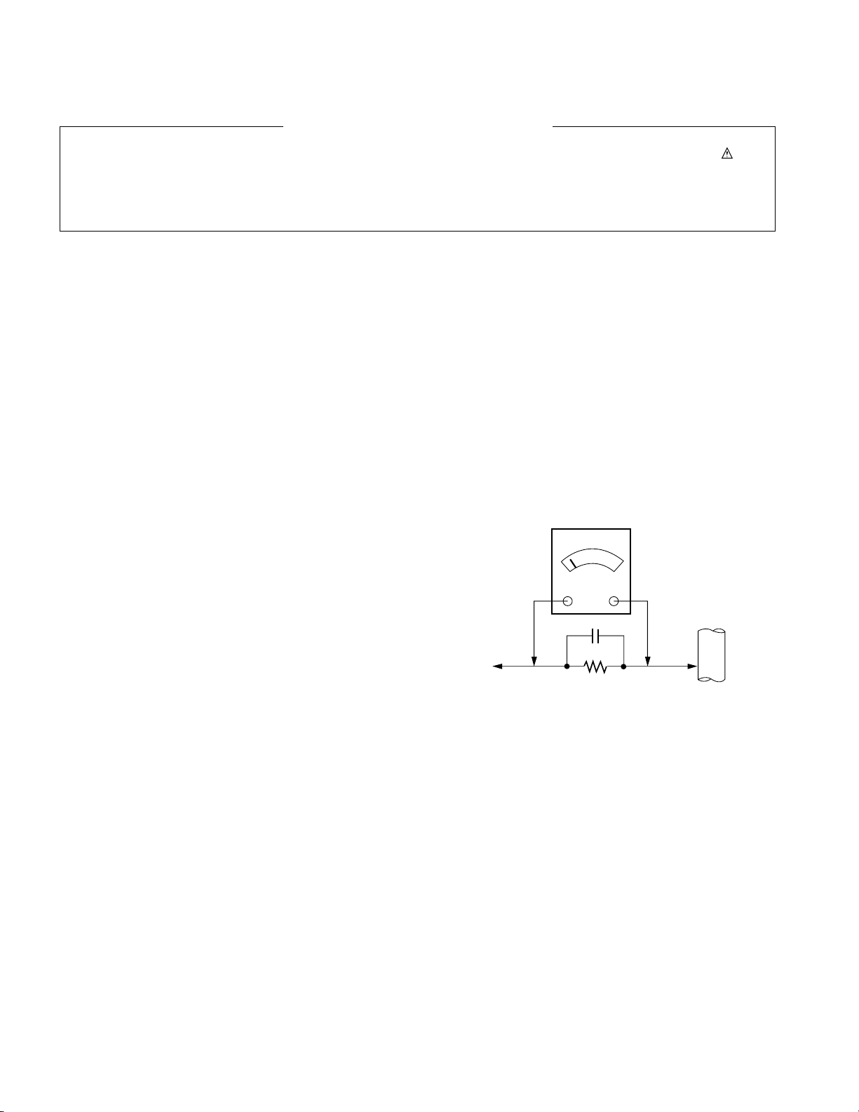
Leakage Current Hot Check (See below Figure)
Plug the AC cord directly into the AC outlet.
Do not use a line Isolation Transformer during this check.
Connect 1.5K/10watt resistor in parallel with a 0.15uF capacitor
between a known good earth ground (Water Pipe, Conduit, etc.)
and the exposed metallic parts.
Measure the AC voltage across the resistor using AC voltmeter
with 1000 ohms/volt or more sensitivity.
Reverse plug the AC cord into the AC outlet and repeat AC voltage
measurements for each exposed metallic part. Any voltage
measured must not exceed 0.75 volt RMS which is corresponds to
0.5mA.
In case any measurement is out of the limits specified, there is
possibility of shock hazard and the set must be checked and
repaired before it is returned to the customer.
Leakage Current Hot Check circuit
1.5 Kohm/10W
To Instrument’s
exposed
METALLIC PARTS
Good Earth Ground
such as WATER PIPE,
CONDUIT etc.
AC Volt-meter
IMPORTANT SAFETY NOTICE
0.15uF
Page 4

- 4 -
LGE Internal Use OnlyCopyright © 2007 LG Electronics. Inc. All right reserved.
Only for training and service purposes
CAUTION: Before servicing receivers covered by this service
manual and its supplements and addenda, read and follow the
SAFETY PRECAUTIONS on page 3 of this publication.
NOTE: If unforeseen circumstances create conflict between the
following servicing precautions and any of the safety precautions on
page 3 of this publication, always follow the safety precautions.
Remember: Safety First.
General Servicing Precautions
1. Always unplug the receiver AC power cord from the AC power
source before;
a. Removing or reinstalling any component, circuit board
module or any other receiver assembly.
b. Disconnecting or reconnecting any receiver electrical plug or
other electrical connection.
c. Connecting a test substitute in parallel with an electrolytic
capacitor in the receiver.
CAUTION: A wrong part substitution or incorrect polarity
installation of electrolytic capacitors may result in an
explosion hazard.
2. Test high voltage only by measuring it with an appropriate high
voltage meter or other voltage measuring device (DVM,
FETVOM, etc) equipped with a suitable high voltage probe.
Do not test high voltage by "drawing an arc".
3. Do not spray chemicals on or near this receiver or any of its
assemblies.
4. Unless specified otherwise in this service manual, clean
electrical contacts only by applying the following mixture to the
contacts with a pipe cleaner, cotton-tipped stick or comparable
non-abrasive applicator; 10% (by volume) Acetone and 90% (by
volume) isopropyl alcohol (90%-99% strength)
CAUTION: This is a flammable mixture.
Unless specified otherwise in this service manual, lubrication of
contacts in not required.
5. Do not defeat any plug/socket B+ voltage interlocks with which
receivers covered by this service manual might be equipped.
6. Do not apply AC power to this instrument and/or any of its
electrical assemblies unless all solid-state device heat sinks are
correctly installed.
7. Always connect the test receiver ground lead to the receiver
chassis ground before connecting the test receiver positive
lead.
Always remove the test receiver ground lead last.
8. Use with this receiver only the test fixtures specified in this
service manual.
CAUTION: Do not connect the test fixture ground strap to any
heat sink in this receiver.
Electrostatically Sensitive (ES) Devices
Some semiconductor (solid-state) devices can be damaged easily
by static electricity. Such components commonly are called
Electrostatically Sensitive (ES) Devices. Examples of typical ES
devices are integrated circuits and some field-effect transistors and
semiconductor "chip" components. The following techniques
should be used to help reduce the incidence of component
damage caused by static by static electricity.
1. Immediately before handling any semiconductor component or
semiconductor-equipped assembly, drain off any electrostatic
charge on your body by touching a known earth ground.
Alternatively, obtain and wear a commercially available
discharging wrist strap device, which should be removed to
prevent potential shock reasons prior to applying power to the
unit under test.
2. After removing an electrical assembly equipped with ES
devices, place the assembly on a conductive surface such as
aluminum foil, to prevent electrostatic charge buildup or
exposure of the assembly.
3. Use only a grounded-tip soldering iron to solder or unsolder ES
devices.
4. Use only an anti-static type solder removal device. Some solder
removal devices not classified as "anti-static" can generate
electrical charges sufficient to damage ES devices.
5. Do not use freon-propelled chemicals. These can generate
electrical charges sufficient to damage ES devices.
6. Do not remove a replacement ES device from its protective
package until immediately before you are ready to install it.
(Most replacement ES devices are packaged with leads
electrically shorted together by conductive foam, aluminum foil
or comparable conductive material).
7. Immediately before removing the protective material from the
leads of a replacement ES device, touch the protective material
to the chassis or circuit assembly into which the device will be
installed.
CAUTION: Be sure no power is applied to the chassis or circuit,
and observe all other safety precautions.
8. Minimize bodily motions when handling unpackaged
replacement ES devices. (Otherwise harmless motion such as
the brushing together of your clothes fabric or the lifting of your
foot from a carpeted floor can generate static electricity
sufficient to damage an ES device.)
General Soldering Guidelines
1. Use a grounded-tip, low-wattage soldering iron and appropriate
tip size and shape that will maintain tip temperature within the
range or 500
o
F to 600oF.
2. Use an appropriate gauge of RMA resin-core solder composed
of 60 parts tin/40 parts lead.
3. Keep the soldering iron tip clean and well tinned.
4. Thoroughly clean the surfaces to be soldered. Use a mall wirebristle (0.5 inch, or 1.25cm) brush with a metal handle.
Do not use freon-propelled spray-on cleaners.
5. Use the following unsoldering technique
a. Allow the soldering iron tip to reach normal temperature.
(500
o
F to 600oF)
b. Heat the component lead until the solder melts.
c. Quickly draw the melted solder with an anti-static, suction-
type solder removal device or with solder braid.
CAUTION: Work quickly to avoid overheating the circuit
borad printed foil.
6. Use the following soldering technique.
a. Allow the soldering iron tip to reach a normal temperature
(500
o
F to 600oF)
b. First, hold the soldering iron tip and solder the strand against
the component lead until the solder melts.
c. Quickly move the soldering iron tip to the junction of the
component lead and the printed circuit foil, and hold it there
only until the solder flows onto and around both the
component lead and the foil.
CAUTION: Work quickly to avoid overheating the circuit
board printed foil.
d. Closely inspect the solder area and remove any excess or
splashed solder with a small wire-bristle brush.
SERVICING PRECAUTIONS
Page 5

- 5 -
LGE Internal Use OnlyCopyright © 2007 LG Electronics. Inc. All right reserved.
Only for training and service purposes
IC Remove/Replacement
Some chassis circuit boards have slotted holes (oblong) through
which the IC leads are inserted and then bent flat against the
circuit foil. When holes are the slotted type, the following technique
should be used to remove and replace the IC. When working with
boards using the familiar round hole, use the standard technique
as outlined in paragraphs 5 and 6 above.
Removal
1. Desolder and straighten each IC lead in one operation by gently
prying up on the lead with the soldering iron tip as the solder
melts.
2. Draw away the melted solder with an anti-static suction-type
solder removal device (or with solder braid) before removing the
IC.
Replacement
1. Carefully insert the replacement IC in the circuit board.
2. Carefully bend each IC lead against the circuit foil pad and
solder it.
3. Clean the soldered areas with a small wire-bristle brush.
(It is not necessary to reapply acrylic coating to the areas).
"Small-Signal" Discrete Transistor
Removal/Replacement
1. Remove the defective transistor by clipping its leads as close as
possible to the component body.
2. Bend into a "U" shape the end of each of three leads remaining
on the circuit board.
3. Bend into a "U" shape the replacement transistor leads.
4. Connect the replacement transistor leads to the corresponding
leads extending from the circuit board and crimp the "U" with
long nose pliers to insure metal to metal contact then solder
each connection.
Power Output, Transistor Device
Removal/Replacement
1. Heat and remove all solder from around the transistor leads.
2. Remove the heat sink mounting screw (if so equipped).
3. Carefully remove the transistor from the heat sink of the circuit
board.
4. Insert new transistor in the circuit board.
5. Solder each transistor lead, and clip off excess lead.
6. Replace heat sink.
Diode Removal/Replacement
1. Remove defective diode by clipping its leads as close as
possible to diode body.
2. Bend the two remaining leads perpendicular y to the circuit
board.
3. Observing diode polarity, wrap each lead of the new diode
around the corresponding lead on the circuit board.
4. Securely crimp each connection and solder it.
5. Inspect (on the circuit board copper side) the solder joints of
the two "original" leads. If they are not shiny, reheat them and if
necessary, apply additional solder.
Fuse and Conventional Resistor
Removal/Replacement
1. Clip each fuse or resistor lead at top of the circuit board hollow
stake.
2. Securely crimp the leads of replacement component around
notch at stake top.
3. Solder the connections.
CAUTION: Maintain original spacing between the replaced
component and adjacent components and the circuit board to
prevent excessive component temperatures.
Circuit Board Foil Repair
Excessive heat applied to the copper foil of any printed circuit
board will weaken the adhesive that bonds the foil to the circuit
board causing the foil to separate from or "lift-off" the board. The
following guidelines and procedures should be followed whenever
this condition is encountered.
At IC Connections
To repair a defective copper pattern at IC connections use the
following procedure to install a jumper wire on the copper pattern
side of the circuit board. (Use this technique only on IC
connections).
1. Carefully remove the damaged copper pattern with a sharp
knife. (Remove only as much copper as absolutely necessary).
2. carefully scratch away the solder resist and acrylic coating (if
used) from the end of the remaining copper pattern.
3. Bend a small "U" in one end of a small gauge jumper wire and
carefully crimp it around the IC pin. Solder the IC connection.
4. Route the jumper wire along the path of the out-away copper
pattern and let it overlap the previously scraped end of the good
copper pattern. Solder the overlapped area and clip off any
excess jumper wire.
At Other Connections
Use the following technique to repair the defective copper pattern
at connections other than IC Pins. This technique involves the
installation of a jumper wire on the component side of the circuit
board.
1. Remove the defective copper pattern with a sharp knife.
Remove at least 1/4 inch of copper, to ensure that a hazardous
condition will not exist if the jumper wire opens.
2. Trace along the copper pattern from both sides of the pattern
break and locate the nearest component that is directly
connected to the affected copper pattern.
3. Connect insulated 20-gauge jumper wire from the lead of the
nearest component on one side of the pattern break to the lead
of the nearest component on the other side.
Carefully crimp and solder the connections.
CAUTION: Be sure the insulated jumper wire is dressed so the
it does not touch components or sharp edges.
Page 6
- 6 -
SPECIFICATION
LGE Internal Use OnlyCopyright © 2007 LG Electronics. Inc. All right reserved.
Only for training and service purposes
1. General Specification
NOTE : Specifications and others are subject to change without notice for improvement
.
NO Item Content Remark
1 User Model Name 20LS5RC-ZA : PAL/SECAM (EU)
2 Feature 20.1” LCD TV
3 Chassis Name LP68F
4 General Scope External SW PR(
D/E), VOL(F/G), OK, MENU, INPUT, POWER 8Keys
& Adj.
5 Power Cord Length : 1.87±0.04 M NATION
Shape : Wall-out,
Color : BLACK
6 Power Adapter No
7 LCD Module Feature Type TFT Color LCD Module
Active Display Area 640(H) x 480(V)
Pixel Pitch [mm] 0.6375mm(H) x 0.2125mm(V) x RGB
Electrical interface TTL LPL
Color Depth 8 bit, 16.7M colors P/N :
Size [mm] 432(W) x 331.5(H) x 25.0(D) EAJ30338001
Surface Treatment Hard Coating(3H) & Anti Glare (HAZE 3%)
treatment of the front polarizer
Operating Mode Normally Black
Back light Unit 6 CCFL (6 lamps)
R/T Typ 25ms(R.T : 12ms + F.T. : 13ms)
No.
1 Product Dimension Width (W) Length (D) Height (H)
Before Packing 474.1 184.3 464.6
After Packing 537 173 483
2 Product Weight Only SET 6.45kg (LPL)
With BOX 8.3kg (LPL)
3 Container Individual or Palletizing 20ft 40ft
Loading Indi. Wooden Indi. Wooden
Quantity 624 576 1248 1152
4 Stand Assy Type Base detachable
Size (W x D x H) 343.9(W) x 184.3(D) x 76.2(H)
Tilt Degree -3(-0/+3) ~ +10(±2) dgree
Tilt force Target 1.5Kgf (0.8Kgf ~ 2.0Kgf)
Swivel Degree - NON
Swivel Force - NON
5 Appearance General Refer to Standard of LG(55)G1-1020
Item Content
Remark
2. Mechanical specification
Page 7
- 7 -
LGE Internal Use OnlyCopyright © 2007 LG Electronics. Inc. All right reserved.
Only for training and service purposes
3. Engineering Specification
No. ITEM Specification Remark
1 ENERGY VIDEO POWER CONSUMPTION LED COLOR
Normal Active ≤ 60W Green
Stand by Off ≤ 1W(110V) Red
≤ 1W(220V)
2 D-SUB 1 : RED 2 : Green For service only
Pin configuration 3 : Blue 4 : ID2 (GND)
5 : S.T (GND) 6 : RED GND
7 : Green GND 8 : Blue GND
9 : N.C 10 : D-GND
11: ID0(GND) 12 :SDA
13: H-Sync 14 : V-Sync
15: SCL Shell : GND
3 Control Function 1) Contrast/ Brightness/ Colour/ Sharpness/(Tint)
2) Power On/Off, Input select, Menu, OK, Volume(
F,G), PR(D,E)
4. Optical Characteristic
No Item Specification Remark
Min Tpy Max
1 Viewing Angle R/L 89/89
<CR≥10> U/D 89/89
2 Luminance Luminance (cd/m
2
) 320 400 PSM : Dynamic, CSM: Cool
White luminance uniformity 75% 80% White (100 IRE)
3 Contrast Ratio CR 2400 3000 All white/ All black
4 CIE Color Coordinates White Wx 0.298 0.313 0.328 In AV input
(Warm) Wy 0.314 0.329 0.344 PSM : Dynamic
White Wx 0.270 0.285 0.300 White (85 IRE)
(Normal) Wy 0.278 0.293 0.308
White Wx 0.261 0.276 0.291
(Cool) Wy 0.268 0.283 0.298
Page 8

- 8 -
5. Outgoing Condition
LGE Internal Use OnlyCopyright © 2007 LG Electronics. Inc. All right reserved.
Only for training and service purposes
No Item Condition Remark
1 Power Off
2 Volume Level 30
3 Main Picture Input TV
4 Main Last Channel Pr 01
5 Mute Off
6 STATION Auto Programme To set System
Storage from
Search
Manual Programme To set Storage
System
Band
Channel
Fine
Search
Name
Programme Edit To set
Favourite Programme Off
7 PICTURE PSM Dynamic
Standard
Mild
Game
User Contrast 100
Brightness 50
Colour 60
Sharpness 50
Tint 0
CSM Cool
Normal
Warm
User Red 0
Green 0
Blue 0
Reset To set
8 SOUND SSM Flat
Music
Movie
Sports
User
AVL Off
Balance 0
9 TIME Clock -- : --
Off time -- : -- Off
On time -- : --
Pr.1
Vol. 30
Off
Auto sleep Off
10 SPECIAL Language English 16 Language
Country Others 30 Teletext Language
Child Lock Off
Page 9
- 9 -
LGE Internal Use OnlyCopyright © 2007 LG Electronics. Inc. All right reserved.
Only for training and service purposes
1. Application Range
These documents is applied to 20" LCD TV(chassis : LP68F)
2. Designation
1) The adjustment is according to the order which is
designated and which must be followed, according to the
plan which can be changed only on agreeing.
2) Power Adjustment : Free Voltage
3) Magnetic Field Condition : Nil.
4) Input signal Unit : Product Specification Standard
5) Reserve after operation : Above 30 Minutes
6) Adjustment equipments: Color Analyzer(CA-210 or CA-
110), Pattern Generator (MSPG-925L or Equivalent), DDC
Adjustment Jig equipment, SVC remote controller
* Download
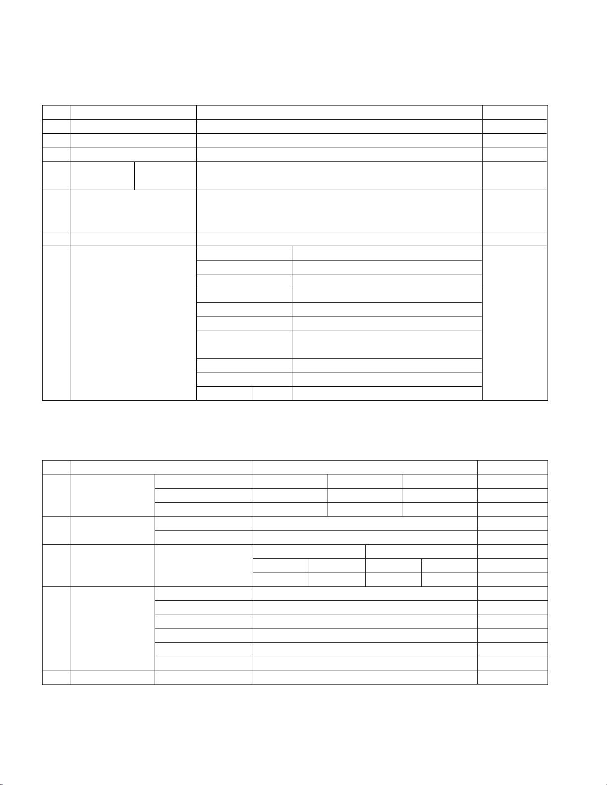
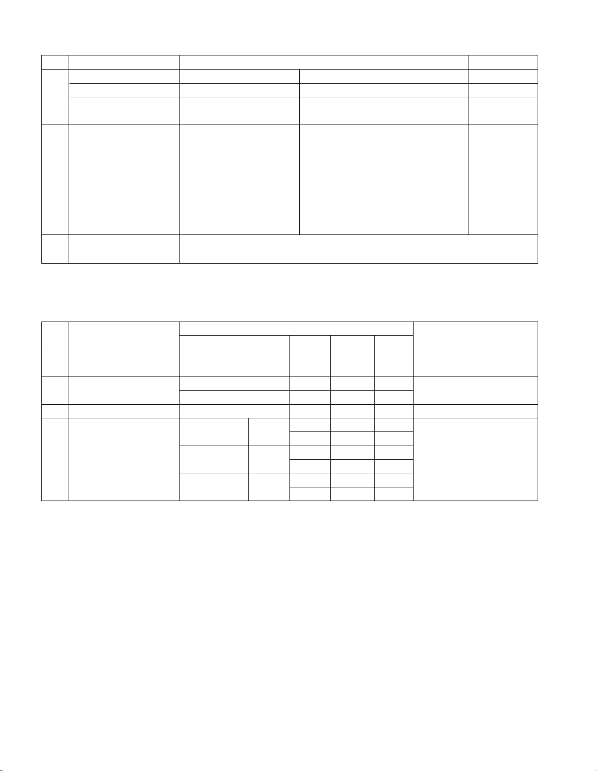
1) Execute ISP program “Mstar ISP Utility” and then click
“Config” tab.
2) Set as below, and check “Auto Detect” and check “OK”
message. If display “ERROR”, check connect computer,
jig, and set.
3) Click “Connect”tab. If flash memory is detected normally,
Flash memory type will be displayed.
MX25L4005 (Flash Memory)
4) Click “Read” tab, and then load download file(XXXX.bin) by
clicking “Read”.
5) Click “Auto” tab and set as below, and then click “Run”.
6) After downloading, check “OK” message.
3. Main PCB check process
* APC - After Manual - Insert, executing APC
3.1. ADC Process
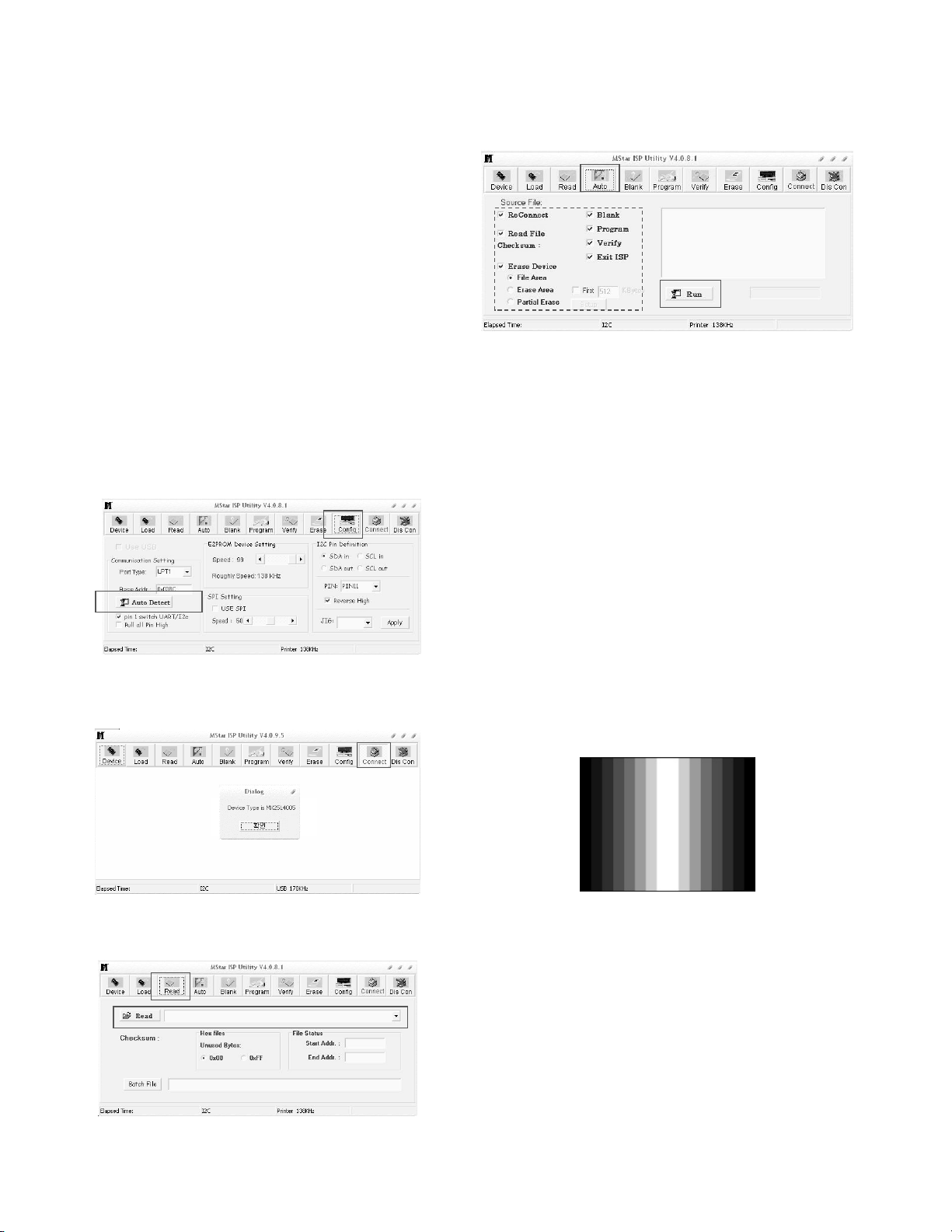
(1) PC input ADC
1) Auto RGB Gain/Offset Adjustment
(a) Convert to PC in Input-source
(b) Signal equipment displays.
Output Voltage : 730 mVp-p
Impress Resolution XGA(1024x768@60Hz)
Pattern : gray pattern that left & right is black and
center is white signal(Refer below picture)
(Model:60, Pattern:28 at MSPG925L)
(c) Adjust by commanding AUTO_COLOR_ADJUST
(0xF1) 0x00 0x02 instruction.
2) Confirmation
(a) We confirm whether “0x8C” address of EEPROM
“0xB4” is “0xAA” or not.
(b) If “0x8C” address of EEPROM “0xB4” isn’t “0xAA”,
we adjust once more.
(c) We can confirm the ADC values from “0x00~0x05”
addresses in a page “0xB4”.
3.2. Function Check
: Check display and sound (cf. work instruction)
(1) TV
(2) AV1 (SCART)
(3) AV2 (CVBS/ S-Video)
(4) RGB (PC : 1024 x768 @ 60Hz)
(5) PC Audio In and H/P Sound Output
* Display and Sound check is executed by Remote control.
ADJUSTMENT INSTRUCTION
(2) OK
(1)
(5)
(5)
(6)
..........
OK
(4)
filexxx.bin
3)
Page 10
3.3. RS-232 check
- Check RS-232 communication
1) Connect “RS-232 Check Jig” to RS-232 Jack in rear input.
* RS-232 Check Jig : Jig which has a wired connection
between Pin2 ~ Pin3 in D-sub 9pin
2) Press “OP1” on SVC remote.
3) If RS-232 interface check is done successfully, “OK” OSD
will appear.
4) If failed, “NG” OSD will appear.
4. Total Assembly line process
4.1. Adjustment Preparation
(1) Above 30 minutes Heat-run in RF no signal
(2)15 Pin D-Sub Jack is connected to the signal of Pattern
Generator.
4.2. Confirm color coordinate of AV2
(1) Set Input to AV2.
(2) Input signal : CVBS, PAL @ 50Hz
Full White 216/255 gray level (85 IRE, Model : 202
Patter : 78 at MSPG925L)
(3) Set PSM : Dynamic / CSM : Cool
(4) Confirm whether x = 0.276
±0.03, y = 0.283±0.03, Y ≥ 250
or not.
4.3. Other quality
(1) Confirm that each items satisfy under standard condition
that was written product spec.
(2) Confirm Video and Sound at each source.
1) AV
(a) Select input AV1 and check whether picture is
displayed or not. - Check whether SCART output
picture is displayed or not.
(b) Select input AV2(S-video) and check whether picture
is displayed or not.
(c) Select input AV2(CVBS) and check whether picture
is displayed or not.
2) TV : Select input TV and check below item.(In Gumi factory)
C05(E05) – Check TELETEXT Function (Applicable
to the model that has Teletext code set-up item in
Product spec)
C07(E07) – Check Nicam DUAL
C52 (E52) – Check Nicam Stereo
4.4. Power Consumption confirmation
- Check if Power LED Color and Power Consumption operate
as standard.
1) Measurement Condition : 230V@ 50Hz (Analog)
2) Confirm Stand-by operation
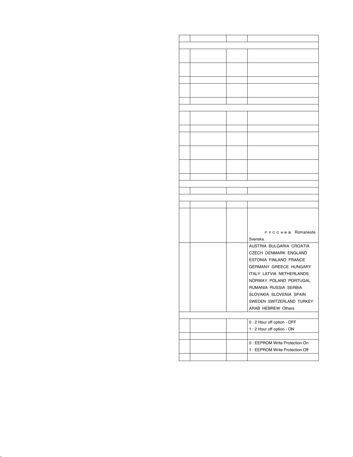
4.5. Option data setting (SVC OSD setting)
- 10 -
LGE Internal Use OnlyCopyright © 2007 LG Electronics. Inc. All right reserved.
Only for training and service purposes
No.
1
2
3
4
5
1
2
3
4
5
6
1
1
2
3
1
2
3
4
Item
Option 1
200R
ACMS
Text
CH+AU
BOOSTER
Option 2
SYS
A2ST
I II SAVE
HDEV
V-Curve
MONO
Option 3
KEY-TYPE
Option 4
Default Language
Lang
T-Lang
Option 5
2HR-OFF
TV-LINK-TUNER
FACTORY-MODE
CHANNEL-MUTE
Condition
0
1
1
0
0
0
1
0
0
0
0
2
3
1
0
1
0
0
1
Remark
0 : 200 PR Off
1 : 200 PR On
0 : ACMS Off
1 : ACMS On
0 : TOP, 1: FOLF
0 : Except below area
1 : China, Australia
0 : BG/I/DK/L
1 : BG/I/DK/M
Acting FM-ST after checking Nicam
0 : I II SAVE Off
1 : I II SAVE On
0 : Except below area
1 : China
0 : Turbo Volume Off
1 : Turbo Volume On
2 : 8Key
Chesky Dansk Deutsch English
Español Italiano Français Magyar
Norsk
Nederlands Polski Português
Suomi
@@@@@@@6K?g
N@@@eI'@@g
?@@@e?V'@g
J@@5fN@g
7@@Hf?@g
@@5?fJ@g
@@H?e?W&5g
?J@@fO&(Yg
?7@@@@@@@0Y?g
J@@?hg
7@5?hg
@@H?hg
@5
?J@?
?@@@
@@@@f?@@@g
3@@Hf?N@5g
N@@Lf?J@Hg
?3@1f?75?g
?V'@L?eJ@H?g
N@)Xe75h
?3@1?J@Hh
?N@@W&5?h
3@@(Y?h
N@@Hhe
?@@?he
?@@?he
?@@?he
?@@?he
?@@?he
?@@@@@@?h
W2@@@6KO@?h
7@(MI'@@@?h
@(Y??V'@@?h
?J@HfN@@?h
?7@?f?@@?h
?@@?f?@@?h
?@@?
?@@?
?@@?
?@@?g?@h
?3@?gJ@h
?N@Lf?W&@h
@)X?eW&@@h
3@)K?O&@@@h
V4@@@@0?4@h
W2@@@6KO@?h
7@(MI'@@@?h
@(Y??V'@@?h
?J@HfN@@?h
?7@?f?@@?h
?@@?f?@@?h
?@@?
?@@?
?@@?
?@@?g?@h
?3@?gJ@h
?N@Lf?W&@h
@)X?eW&@@h
3@)K?O&@@@h
V4@@@@0?4@h
@@@@fW2@@g
@@@Hf7Y@@g
@@@?f@?3@g
@@@?f@?V'g
@@@?e?J@?h
@@@?eW&5?h
@@@??O&@Y?h
@@@@@@@@@6X?g
@@@?f@@1?g
@@@?f@@@?g
@@@?f3@@?g
@@@?fN@@Lg
@@@Lf?3@)X?f
@@@@f?V4@)?f
@@@@@?e@@@@g
N@@@H?eN@@@g
?@@@fJ@@@g
?@@@f7@@@g
?@@@e?J@@@@g
?@@@e?7Y@@@g
?@@@eJ5?@@@g
?@@@?W.Y?@@@g
?@@@?7H??@@@g
?@@@W5e?@@@g
?@@@@He?@@@g
?@@@@?e?@@@g
J@@@@?eJ@@@g
@@@@@?e@@@@g
?/X?eW.h
?V/K?O.Yh
V4@0Y?h
@@@@@?e@@@@g
N@@@H?e?@@@g
?@@@f7@@@g
?@@@e?J@@@@g
?@@@e?7Y@@@g
?@@@eJ5?@@@g
?@@@?W.Y?@@@g
?@@@?7H??@@@g
?@@@W5e?@@@g
?@@@@He?@@@g
?@@@@?e?@@@g
?@@@5?e?@@@g
J@@@fJ@@@g
@@@@@?e@@@@g
Romaneste
Svenska
AUSTRIA BULGARIA CROATIA
CZECH DENMARK ENGLAND
ESTONIA FINLAND FRANCE
GERMANY GREECE HUNGARY
ITALY LATVIA NETHERLANDS
NORWAY POLAND PORTUGAL
RUMANIA RUSSIA SERBIA
SLOVAKIA SLOVENIA SPAIN
SWEDEN SWITZERLAND TURKEY
ARAB HEBREW Others
0 : 2 Hour off option - OFF
1 : 2 Hour off option - ON
0 : EEPROM Write Protection On
1 : EEPROM Write Protection Off
Page 11

LGE Internal Use OnlyCopyright © 2007 LG Electronics. Inc. All right reserved.
Only for training and service purposes
5. Adjustment Command
5.1. Adjustment Command (LENGTH=84)
5.2. EEPROM DATA READ
(1) Signal Table
(2) Command Set
Purpose : To read the appointment Address of E2PROM by
128(80h)-byte
5.3. E2PROM Data Write
(1) Signal Table
LEN : 84h+Bytes
CMD : 8Eh
ADH : E2PROM Slave Address(A0,A2,A4,A6,A8),
Not 00h(Reserved by BufferToEEPROM)
ADL : E2PROM Sub Address(00~FF)
Data : Write data
(2) Command Set
<Purpose>
1) EDID write : 16-byte by 16-byte, 8 order (128-byte) write
(TO “00 – 7F” of “EEPROM Page A4”)
2)FOS Default write : 16-mode data (HFh, HFl, VF, STD,
HP, VP, Clk, ClkPh, PhFine) write
3) Random Data write : write the appointment Address of
E2PROM
5.4. VRAM Read
1) Send CMD(70h) to read Video RAM value from MICOM
And save its value to 128-Bytes Buffer(Common Buffer for
the use of EDID).
2) Delay 500ms(Time to wait and read vZideo RAM from
MICOM)
3) Be transmitted the contents of MICOM’s 128-bytes Buffer to
PC.(128th Data is the CheckSum of 127-bytes data : That’s
OK if the value of adding 128-bytes Data is Zero)
- 11 -
VAL
00
00
data
00
00 – 100
00 – 100
00 – 100
00 – 100
00 – FF
00 – FF
00 – FF
00 – 7F
00 – 7F
00 – 7F
00 – 3F
00 - 64
02
0, 1, 2, 3
00, FF
0, 1, 2
Description
EEPROM all clear
EEPROM Read
EEPROM Write by
some values
Color Save
They have different
range each mode,
FOS Adjustment
Drive adjustment
Offset adjustment
Bright adjustment
Luminance adjustment
Auto COLOR
Adjustment
0: COOL
1: NORMAL
2: WARM
3: USER
00: Factory mode Off
FF:Factory mode On
0 : TV
1 : AV1
2 : AV2
3 : Component
4 : RGB
5 : DVI
No.
1
2
3
4
5
6
7
8
9
10
11
12
13
14
15
16
17
18
19
20
Adjustment Contents
EEPROM ALL INIT.
EEPROM Read
EEPROM Write
COLOR SAVE
(R/G/B cutoff, Drive,
Contrast, Bright)
H POSITION
V POSITION
CLOCK
PHASE
R DRIVE
G DRIVE
B DRIVE
R CUTOFF
G CUTOFF
B CUTOFF
BRIGHT
CONTRAST
AUTO_COLOR_
ADJUST
CHANGE_COLOR_
TEMP
FACTORY_
DEFAULT
AUTO_
INPUTCHANGE
CMD(hex)
E4
E7
E8
EB
20
30
90
92
16
18
1A
80
82
84
10
12
F1
F2
F3
F4
ADR
00
00
00
00
00
00
00
00
00
00
00
00
00
00
00
00
00
00
00
00
ST OP
A
AA 506E 03 CMD ADH84+ n
ADL
A
CSAA
Data_1
A
. . . Data_n
A
No.
1
2
Adjustment contents
EEPROM WRITE
CMD(hex)E8LEN
94
84+n
Details
16-Byte Write
n-byte Write
ADL(hex)
0
80
0
80
0
80
0
80
Details
0-Page 0~7F Read
0-Page 80~FF Read
1-Page 0~7F Read
1-Page 80~FF Read
2-Page 0~7F Read
2-Page 80~FF Read
3-Page 0~7F Read
3-Page 80~FF Read
Adjustment Contents
EEPROM READ
CMD(hex)E7ADR(hex)
A0
A2
A4
A6
A
A D1 6F
ST OP
ST ART
A
A
A
A
A 50 6E 03 CM D ADH
ST ART
A
A ADL A CS
128 Bytes
Delay 100ms
CS
6F
ST ART
84
ST ART
AA
ST ART
A 50
6E
A
A
84
03 70 00
A
A
A
A 00
A Data1
. . . Data12
A
NA
ST OP
A CS
ST OP
Page 12

LGE Internal Use OnlyCopyright © 2007 LG Electronics. Inc. All right reserved.
Only for training and service purposes
PR 0
PR 1
PR 2
PR 3
PR 4
PR 5
PR 6
PR 7
PR 8
PR 9
PR 10
PR 11
PR 12
PR 13
PR 14
PR 15
PR 16
PR 17
PR 18
PR 19
PR 20
PR 21
PR 22
PR 23
PR 24
PR 25
PR 26
PR 27
PR 28
PR 29
PR 30
PR 31
PR 32
PR 33
PR 34
PR 35
PR36
PR 37
PR 38
PR 39
PR 40
PR 41
C 34
C 01
C 05
S 11
C 04
C 07
C 50
C 52
C 41
C 63
C 02
S 07
C 36
C 05
C 51
C41
C 05
C 04
C 31
C 21
C 69
C 08
C 45
C 25
C 07
S 24
C 39
C 29
C 01
C 34
C 04
S 11
C 04
C 50
C 52
C 36
C 05
C 25
C 40
C 01
C 10
C 36
FLOF
FLOF
FLOF
FLOF
FLOF
TOP
FLOF
FLOF
FLOF
FLOF
FLOF
FLOF
FLOF
FLOF
FLOF
DUAL
MONO
STEREO
MONO
DUAL
DUAL
MONO
STEREO
STEREO
STEREO
MONO
DUAL
STEREO
DUAL
STEREO
STEREO
MONO
STEREO
DUAL
STEREO
MONO
MONO
DUAL
MONO
STEREO
STEREO
STEREO
STEREO
MONO
STEREO
MONO
DUAL
MONO
MONO
MONO
STEREO
NICAM
NICAM
NICAM
NICAM
NICAM
NICAM
NICAM
NICAM
A2
A2
NICAM
A2
NICAM
NICAM
NICAM
NICAM
NICAM
DIGITAL
PHILIPS
PHILIPS
FUBK
PHILIPS
Crosshatch
RGB, WHITE
MATRIX C/B
PHILIPS
Crosshatch
Crosshatch
PHILIPS
Colorbar
Crosshatch+Circle
DIGITAL
Crosshatch
DIGITAL
Crosshatch
Colorbar
DIGITAL
DIGITAL
DIGITAL
DIGITAL
Crosshatch(16:9)
Monoscope
Monoscope
SMPTE
Colorbar
White Raster
White Raster
Crosshatch+Circle
Colorbar
Philips
Color Bar (2)
Monoscope
Color Bar(2)
Color Bar
Philips
SECAM-DK
PAL-BG
PAL-BG
PAL-I
SECAM-BG
PAL-BG
PAL-BG
PAL-BG
PAL-I
PAL-I
PAL-L
PAL-L
PAL-L
PAL-B
PAL-G
PAL-I
SECAM-D
PAL-B
PAL-G
PAL-I
PAL-I
NTSC-M
SECAM-L
SECAM-L
PAL-B
NTSC-M
PAL-B
PAL-BG
PAL-BG
PAL-DK
PAL-BG
PAL-I
PAL-BG
SECAM-DK
PAL-BG
SECAM-L
PAL-B/G
PAL-B/G
PAL-B/G
SECAM D/K
PAL-D/K
PAL-D/K
LGE Gumi
LGEMA
LGEWA
LGENT
1Khz
Ger, Stereo 1K,3Khz
Sweep
400Hz
Sweep
CHI Dual 1K, 3Khz
575.25
45.25
175.25
231.25
62.25
189.25
703.25
719.25
631.25
807.25
55.75
152.75
591.25
175.25
711.25
631.25
93.25
62.25
551.25
471.25
855.25
687.25
200.25
663.25
189.25
327.25
615.25
535.25
45.25
575.25
175.25
231.25
62.25
703.25
719.25
591.25
175.25
503.25
623.25
49.75
200.25
695.25
- 12 -
6. Preset CH information
PIF[MHz] SYSTEM VIDEO TXT NAME
SOUND
System Mode
Page 13

- 13 -
LGE Internal Use OnlyCopyright © 2007 LG Electronics. Inc. All right reserved.
Only for training and service purposes
TROUBLESHOOTING
No power
(LED indicator off)
Check short of main B/D
or Change Lips.
Change IC903.
Change LED Assy.
Check 15V or 5V
of Lips.
Check Output of
IC903.
Check LED Assy.
Check P901, P270, Connector.
Fail
Fail
Change Q904.
Check Output of
Q904.
Fail
Pass
Fail
Pass
Pass
Pass
:[A]Process
Page 14

LGE Internal Use OnlyCopyright © 2007 LG Electronics. Inc. All right reserved.
Only for training and service purposes
- 14 -
No Raster
Check LED Status
on display unit.
Check the input/
Output of IC100.
Check
IC900, IC901, IC906, IC908,
IC909, IC910.
Check inverter
connector or inverter.
Check inputting source cable
and jack.
Repeat [A] PROCESS.
Fail
Change IC900, IC901, IC906,
IC908, IC909, IC910.
Fail
Change IC100.
Fail
Change inverter connector or
inverter.
Fail
Change panel link cable or
module.
Fail
Check panel link
cable or module.
Pass
Pass
Pass
Pass
Pass
:[B]Process
Page 15

- 15 -
LGE Internal Use OnlyCopyright © 2007 LG Electronics. Inc. All right reserved.
Only for training and service purposes
No Raster on AV Signal
(Component, CVBS, S-VHS)
No Raster on TV(RF) signal
Change R104, R106, R108,
R131, L822, L800, L801.
Check the signal of
R104, R106, R108, R131
L822, L800, L801.
Repeat
[A] Process .
Check the output
of TU500.
Check the
input/ output of IC100.
Check inputting source cable
and jack.
Fail
Fail
Fail
Fail
Re-solder or change the defect part.
Check X101.
Check 5V of TU500.
Re-solder or change the
defect part.
Pass
Pass
Pass
Page 16

- 16 -
LGE Internal Use OnlyCopyright © 2007 LG Electronics. Inc. All right reserved.
Only for training and service purposes
No Sound
Check the speaker wire
Change source input.
Check the
input source.
Fail
Pass
Re-solder or Change the
defect part.
Check X301.
Check the input/output
of IC100
Fail
Pass
Re-solder or change the
defect part.
Check the input/output
of IC400
Fail
Pass
Change the speaker
Check the speaker
Fail
Pass
Page 17

- 17 -
LGE Internal Use OnlyCopyright © 2007 LG Electronics. Inc. All right reserved.
Only for training and service purposes
BLOCK DIAGRAM
IR detector
5V
LVDS M ODULE
MX25L4005A
(Serial Flash)
Control Board(Tact Switch)
LED
Speaker Left
Speaker Right
TTL MODULE
15V
5V
15V
12V_Panel
5V
5V
15V
LIPS
RGB in
Audio out
Audio in
CVBS in
Video in
Audio in
Y in
C in
CVBS out
Control in/out
EEPROM
(24C64)
CVBS
Jack
S-Video
Jack
Stereo-In
(Optio n)
H/P
Output
LED / IR / Contro l
Power
Video
Audio
Dat a
Address
Data
CLK,DQM,
WEZ,CASZ,RASZ
EEPROM
(24C02)
M12L1 6161A -5T G
(SD RAM )
CVBS TunerCVBS Tuner
SCL /SDA
SCL /SDA
SCL /SDA
SIF_OU T
CVBS OUT
MST96585
(Scaler + Video Decoder)
SCART
Jack
D-Sub
(Optio n)
RS-232C
(Optio n)
Rx/Tx
CS4352
(DAC)
3.3V
12V
Regulator
Regulator
Regulator
Regulator
Regulator
5V
1.8V
LED/IR Board
Control
MX232A
(RS-232C)
ON/OFF
PWM_DIM
DIM _ CTL
YDA1 38
(Audio amp)
Rx/Tx
FET Switch
(SI4925BDY)
5V
12V
IF_Video
Page 18

- 18 -
LGE Internal Use OnlyCopyright © 2007 LG Electronics. Inc. All right reserved.
Only for training and service purposes
BLOCK DIAGRAM DESCRIPTION
Power Supply Block (LIPS)
This Block Generates DC Voltage (5V,15V) to Main Control system from AC Power (100-240 V, 50/60 Hz, 1.0A)
Also it has the inverter function that converts input voltage to AC Rms value for the LCD lamp.
Voltage Regulator
Voltage regulator convert the input 5V,15V to proper 1.8V, 3.3V, 5V, 12V for
Main control system.
For shooting heat trouble, we use the voltage regulator IC.
Digital Audio Amplifier
This block is composed of YDA138-EZ and peripheral device
The function of the audio amplifier is that to amplify audio L / R signal transmitted from audio decoder. The audio
signal is amplified according to pre-defined DC volume control curve.
Audio / Video Decoder / Scaler
This block is composed of LGE9655 and peripheral devices.
1) Video Decoder
This Block Selects input Video signals (like CVBS, Y/C, SCART RGB) and output LVDS/ TTL signal through
Scaler.
On decoding, We can control signal like Contrast, Brightness, Sharpness, Color, tint signals including
Adaptive Comb Filter.
2) Audio Decoder
This block analyzes audio input signal through A/V Jack (and PC audio) and Tuner SIF.
The analyzed signals transmitted to audio amplifier.
On decoding, We can control signal like Bass, treble.
3) Scaler
This IC includes A/D Converter and LVDS Transmitter
This IC is directly Inputted Analog Signal and transmits it to LCD Module
4) Micom
This block controls each IC through IIC communication line.
DAC IC (CS4352)
It is composed of CS4352.
The CS4352 is a complete stereo digital-to-analog system including digital interpolation, fifth-order multi-bit
delta-sigma digital-to-analog conversion, digital de-emphasis, analog filtering, and on-chip 2 Vrms line-level
driver.
TUNER
Micom controls this through IIC Line.
TUNER makes CVBS/SIF and transmits CVBS/SIF signal to LGE9655.
Page 19

- 19 -
MEMO
LGE Internal Use OnlyCopyright © 2007 LG Electronics. Inc. All right reserved.
Only for training and service purposes
Page 20

LGE Internal Use OnlyCopyright © 2007 LG Electronics. Inc. All right reserved.
Only for training and service purposes
- 20 -
450
300
200
220
591
590
120
520
580
800
581
210
531
530
400
900
920
910
550
150
EXPLODED VIEW
A21
A2
Page 21

- 21 -
LGE Internal Use OnlyCopyright © 2007 LG Electronics. Inc. All right reserved.
Only for training and service purposes
EXPLODED VIEW PARTS LIST
No. PART NO. DESCRIPTION
120 EAB35995501 Speaker,Full Range A11 EN1227C-6710 3W 8OHM 80DB 300HZ 31 X 78.5 X 21 LUG
150 MCK36017402 Cover MOLD ABS 380 17LS5R/20LS5R ABS, HF-380 CABLE MANAGEMENT_CKD
200 EAJ30338001
LCD,Module-TFT LC201V02-SDA1 VGA 4/3 800 P7 Module(0RT-Pol., NEC D-IC TTL/Mini LVDS) LPL
210 MCK36815003
Cover MOLD HIPS 51SF 20LS5R HIPS 51SF 20LS5R MODULE FIX BRACKET (LPL) RIGHT_CKD
220 MCK36815004
Cover MOLD HIPS 51SF 20LS5R HIPS 51SF 20LS5R MODULE FIX BRACKET (LPL) LEFT_CKD
300 ABJ32624702 Cabinet Assembly 20LS5R LP68A(BB3) 20” 20LS5R Cabinet Assy_CKD
400 ACQ32625206 Cover Assembly 20LS5RC LP68F(BB3) 20” Back Cover Assy ,RS-232C(Hotel)_CKD
450 ADV30635231 Frame Assembly 20LS5RC LP68F 20”” REAR SHIELD ASSY_BB3_RS-232C(Hotel)_CKD
520 EBU38773802 Main Total Assembly 20LS5RC-ZA BRAND LP68F commercial lite SKD
530 EBR31760603 PCB Assembly CONTROL T.T LP68A LS1R-ZK SKD LS1R-ZK SKD
531 MEY30552601 Knob MOLD HIPS 405AF SUB CONTROL KNOB LS1R LS1R CONTROL KNOB
550 EBR35712603 PCB Assembly,Interface INTERFACE T.T LP68A 20LS1R-ZK SKD 20LS1R-ZK SKD (LPL)
580 EAY32636401
Power Supply Assembly AIV-P0032 FREE 20LS1R LCD Lien Chang Electroic Enterprise Co.Ltd
581 EBT36118901 Chassis Assembly POWER(SMPS) - LP68A CORE AC SOCKET C/SKD ASS’Y
590 EBR32541801 PCB Assembly SUB T.T CL81 Mx21A BZF LED+IR
591 MES36625301 Indicator MOLD PMMA LED 20LS5R PMMA 7 PHY .
800 MGJ32259302 Plate,Shield PRESS SPTE 0.3t SHIELD SPTE LAMP 20LS1R CSKD OF 01
900 ACQ32300802 Cover Assembly 20LS5R LP68A(BB3) 20” STAND BASE ASSY,CKD
910 ACQ32300504 Cover Assembly 20LS5R LP68A 20” HINGE BODY COVER ASSY,CKD
920 MCK36017202 Cover MOLD ABS 380 17LS5R/20LS5R ABS, HF-380 STAND BODY,CKD
A2 MKJ37815701 Remote Controller COMPLEX LP69B LS5R W/TXT, W/O PIP , ZA(EUROPE)
A21 MCK36759201 Cover MOLD ABS HF-380 MKJ339814 ABS, HF-380 TX BATTERY COVER
* Note: Safety mark
Page 22

- 22 -
LGE Internal Use OnlyCopyright © 2007 LG Electronics. Inc. All right reserved.
Only for training and service purposes
C100 0CK104CK56A 0603B104K500CT 100nF 10% 50V X7R -55TO+125
C102 0CK104CK56A 0603B104K500CT 100nF 10% 50V X7R -55TO+125
C103 0CK104CK56A 0603B104K500CT 100nF 10% 50V X7R -55TO+125
C104 0CK104CK56A 0603B104K500CT 100nF 10% 50V X7R -55TO+125
C105 0CK104CK56A 0603B104K500CT 100nF 10% 50V X7R -55TO+125
C106 0CK473CK56A C1608X7R1H473KT 47nF 10% 50V X7R -55TO+125
C107 0CK473CK56A C1608X7R1H473KT 47nF 10% 50V X7R -55TO+125
C108 0CK473CK56A C1608X7R1H473KT 47nF 10% 50V X7R -55TO+125
C1089 0CK104CK56A 0603B104K500CT 100nF 10% 50V X7R -55TO+125
C109 0CK473CK56A C1608X7R1H473KT 47nF 10% 50V X7R -55TO+125
C1090 0CK104CK56A 0603B104K500CT 100nF 10% 50V X7R -55TO+125
C1091 0CK105CD56A C1608X7R1A105KT 1uF 10% 10V X7R -55TO+125C
C1092 0CK104CK56A 0603B104K500CT 100nF 10% 50V X7R -55TO+125
C1093 0CK104CK56A 0603B104K500CT 100nF 10% 50V X7R -55TO+125
C110 0CK473CK56A C1608X7R1H473KT 47nF 10% 50V X7R -55TO+125
C111 0CK473CK56A C1608X7R1H473KT 47nF 10% 50V X7R -55TO+125
C112 0CK473CK56A C1608X7R1H473KT 47nF 10% 50V X7R -55TO+125
C113 0CK473CK56A C1608X7R1H473KT 47nF 10% 50V X7R -55TO+125
C114 0CK473CK56A C1608X7R1H473KT 47nF 10% 50V X7R -55TO+125
C115 0CK473CK56A C1608X7R1H473KT 47nF 10% 50V X7R -55TO+125
C116 0CK473CK56A C1608X7R1H473KT 47nF 10% 50V X7R -55TO+125
C117 0CK104CK56A 0603B104K500CT 100nF 10% 50V X7R -55TO+125
C118 0CE106WFKDC MVK4.0TP16VC10M 10uF 20% 16V 16MA -40TO+10
C121 0CK104CK56A 0603B104K500CT 100nF 10% 50V X7R -55TO+125
C122 0CK104CK56A 0603B104K500CT 100nF 10% 50V X7R -55TO+125
C123 0CK225DH94A C2012Y5V225ZFT 2.2uF -20TO+80% 25V Y5V -30
C124 0CK104CK56A 0603B104K500CT 100nF 10% 50V X7R -55TO+125
C127 0CK473CK56A C1608X7R1H473KT 47nF 10% 50V X7R -55TO+125
C128 0CK473CK56A C1608X7R1H473KT 47nF 10% 50V X7R -55TO+125
C129 0CK473CK56A C1608X7R1H473KT 47nF 10% 50V X7R -55TO+125
C131 0CK473CK56A C1608X7R1H473KT 47nF 10% 50V X7R -55TO+125
C132 0CK473CK56A C1608X7R1H473KT 47nF 10% 50V X7R -55TO+125
C133 0CK473CK56A C1608X7R1H473KT 47nF 10% 50V X7R -55TO+125
C134 0CK473CK56A C1608X7R1H473KT 47nF 10% 50V X7R -55TO+125
C135 0CK473CK56A C1608X7R1H473KT 47nF 10% 50V X7R -55TO+125
C137 0CE106WFKDC MVK4.0TP16VC10M 10uF 20% 16V 16MA -40TO+10
C138 0CE106WFKDC MVK4.0TP16VC10M 10uF 20% 16V 16MA -40TO+10
C139 0CE106WFKDC MVK4.0TP16VC10M 10uF 20% 16V 16MA -40TO+10
C140 0CE106WFKDC MVK4.0TP16VC10M 10uF 20% 16V 16MA -40TO+10
C142 0CK104CK56A 0603B104K500CT 100nF 10% 50V X7R -55TO+125
C143 0CK104CK56A 0603B104K500CT 100nF 10% 50V X7R -55TO+125
C144 0CK104CK56A 0603B104K500CT 100nF 10% 50V X7R -55TO+125
C145 0CK104CK56A 0603B104K500CT 100nF 10% 50V X7R -55TO+125
C146 0CE106WFKDC MVK4.0TP16VC10M 10uF 20% 16V 16MA -40TO+10
C148 0CE106WFKDC MVK4.0TP16VC10M 10uF 20% 16V 16MA -40TO+10
C149 0CK104CK56A 0603B104K500CT 100nF 10% 50V X7R -55TO+125
C150 0CK475CC94A C1608Y5V0J475ZT 4.7uF -20TO+80% 6.3V Y5V -
C151 0CC102CK41A C1608C0G1H102JT 1nF 5% 50V C0G -55TO+125C
C152 0CK104CK56A 0603B104K500CT 100nF 10% 50V X7R -55TO+125
C154 0CK105CD56A C1608X7R1A105KT 1uF 10% 10V X7R -55TO+125C
C155 0CK224DK46A 0805B224J500CT 220nF 5% 50V X7R -55TO+125C
C156 0CK104CK56A 0603B104K500CT 100nF 10% 50V X7R -55TO+125
C157 0CK473CK56A C1608X7R1H473KT 47nF 10% 50V X7R -55TO+125
C158 0CK473CK56A C1608X7R1H473KT 47nF 10% 50V X7R -55TO+125
C159 0CK104CK56A 0603B104K500CT 100nF 10% 50V X7R -55TO+125
C161 0CH5200K416 0805N200J500LT 20pF 5% 50V C0G -55TO+125C
C162 0CH5200K416 0805N200J500LT 20pF 5% 50V C0G -55TO+125C
C164 0CE106WFKDC MVK4.0TP16VC10M 10uF 20% 16V 16MA -40TO+10
C168 0CK225DH94A C2012Y5V225ZFT 2.2uF -20TO+80% 25V Y5V -30
C169 0CK225DH94A C2012Y5V225ZFT 2.2uF -20TO+80% 25V Y5V -30
C170 0CK225DH94A C2012Y5V225ZFT 2.2uF -20TO+80% 25V Y5V -30
C171 0CK225DH94A C2012Y5V225ZFT 2.2uF -20TO+80% 25V Y5V -30
C172 0CK104CK56A 0603B104K500CT 100nF 10% 50V X7R -55TO+125
C173 0CK225DH94A C2012Y5V225ZFT 2.2uF -20TO+80% 25V Y5V -30
C174 0CK225DH94A C2012Y5V225ZFT 2.2uF -20TO+80% 25V Y5V -30
C176 0CK104CK56A 0603B104K500CT 100nF 10% 50V X7R -55TO+125
C179 0CK104CK56A 0603B104K500CT 100nF 10% 50V X7R -55TO+125
C180 0CK153CK56A 0603B153K500CT 15nF 10% 50V X7R -55TO+125C
C181 0CK153CK56A 0603B153K500CT 15nF 10% 50V X7R -55TO+125C
C183 0CK104CK56A 0603B104K500CT 100nF 10% 50V X7R -55TO+125
C184 0CK104CK56A 0603B104K500CT 100nF 10% 50V X7R -55TO+125
C185 0CK104CK56A 0603B104K500CT 100nF 10% 50V X7R -55TO+125
C186 0CK104CK56A 0603B104K500CT 100nF 10% 50V X7R -55TO+125
C187 0CK104CK56A 0603B104K500CT 100nF 10% 50V X7R -55TO+125
C188 0CK104CK56A 0603B104K500CT 100nF 10% 50V X7R -55TO+125
C190 0CK104CK56A 0603B104K500CT 100nF 10% 50V X7R -55TO+125
C191 0CK104CK56A 0603B104K500CT 100nF 10% 50V X7R -55TO+125
C192 0CK104CK56A 0603B104K500CT 100nF 10% 50V X7R -55TO+125
C194 0CK104CK56A 0603B104K500CT 100nF 10% 50V X7R -55TO+125
C195 0CK104CK56A 0603B104K500CT 100nF 10% 50V X7R -55TO+125
C196 0CK104CK56A 0603B104K500CT 100nF 10% 50V X7R -55TO+125
C197 0CK104CK56A 0603B104K500CT 100nF 10% 50V X7R -55TO+125
C199 0CE106WFKDC MVK4.0TP16VC10M 10uF 20% 16V 16MA -40TO+10
C250 0CK104CK56A 0603B104K500CT 100nF 10% 50V X7R -55TO+125
C251 0CE107WF6DC MVK6.3TP16VC100M 100uF 20% 16V 110MA -40TO
C252 0CC220CK41A C1608C0G1H220JT 22pF 5% 50V C0G -55TO+125C
C253 0CK104CK56A 0603B104K500CT 100nF 10% 50V X7R -55TO+125
C255 0CC101CK41A C1608C0G1H101JT 100pF 5% 50V C0G -55TO+125
C261 0CC101CK41A C1608C0G1H101JT 100pF 5% 50V C0G -55TO+125
C262 0CC101CK41A C1608C0G1H101JT 100pF 5% 50V C0G -55TO+125
C270 0CC101CK41A C1608C0G1H101JT 100pF 5% 50V C0G -55TO+125
C271 0CC101CK41A C1608C0G1H101JT 100pF 5% 50V C0G -55TO+125
C272 0CC101CK41A C1608C0G1H101JT 100pF 5% 50V C0G -55TO+125
C273 0CE107WF6DC MVK6.3TP16VC100M 100uF 20% 16V 110MA -40TO
C274 0CK104CK56A 0603B104K500CT 100nF 10% 50V X7R -55TO+125
C275 0CE475WJ6DC MVK4.0TP35VC4.7M 4.7uF 20% 35V 15MA -40TO+
C300 0CK104CK56A 0603B104K500CT 100nF 10% 50V X7R -55TO+125
C301 0CK104CK56A 0603B104K500CT 100nF 10% 50V X7R -55TO+125
C303 0CK104CK56A 0603B104K500CT 100nF 10% 50V X7R -55TO+125
LOC. NO. PART NO. DESCRIPTION / SPECIFICATION LOC. NO. PART NO. DESCRIPTION / SPECIFICATION
REPLACEMENT PARTS LIST
DATE: 2007. 08. 17.
CAPACITORs
Page 23

- 23 -
C304 0CK104CK56A 0603B104K500CT 100nF 10% 50V X7R -55TO+125
C306 0CK104CK56A 0603B104K500CT 100nF 10% 50V X7R -55TO+125
C308 0CK104CK56A 0603B104K500CT 100nF 10% 50V X7R -55TO+125
C400 0CK225DH94A C2012Y5V225ZFT 2.2uF -20TO+80% 25V Y5V -30
C4000 0CN1040K949 CH UP050 F104Z-B-B Z 100nF -20TO+80% 50V Y
C4001 0CN1040K949 CH UP050 F104Z-B-B Z 100nF -20TO+80% 50V Y
C401 0CE107WF6DC MVK6.3TP16VC100M 100uF 20% 16V 110MA -40TO
C402 0CK224DH56A 0805B224K250CT 220nF 10% 25V X7R -55TO+125
C403 0CK474DK56A UMK212BJ474KG-T 470nF 10% 50V X7R -40TO+10
C404 0CK224DH56A 0805B224K250CT 220nF 10% 25V X7R -55TO+125
C405 0CK105CF94A 0603F105Z160CT 1uF -20TO+80% 16V Y5V -30TO
C406 0CE107WF6DC MVK6.3TP16VC100M 100uF 20% 16V 110MA -40TO
C407 0CK475EF67A C3216X5R1C475MT 4.7uF 20% 16V X5R -55TO+85
C408 0CK475EF67A C3216X5R1C475MT 4.7uF 20% 16V X5R -55TO+85
C409 0CE227WF6DC MVK8.0TP16VC220M 220uF 20% 16V 80MA -40TO+
C410 0CK105CF94A 0603F105Z160CT 1uF -20TO+80% 16V Y5V -30TO
C411 0CK105CF94A 0603F105Z160CT 1uF -20TO+80% 16V Y5V -30TO
C412 0CE227WF6DC MVK8.0TP16VC220M 220uF 20% 16V 80MA -40TO+
C413 0CK475EF67A C3216X5R1C475MT 4.7uF 20% 16V X5R -55TO+85
C414 0CK104CK56A 0603B104K500CT 100nF 10% 50V X7R -55TO+125
C415 0CK475EF67A C3216X5R1C475MT 4.7uF 20% 16V X5R -55TO+85
C416 0CE106WFKDC MVK4.0TP16VC10M 10uF 20% 16V 16MA -40TO+10
C417 0CK474DK56A UMK212BJ474KG-T 470nF 10% 50V X7R -40TO+10
C418 0CK224DH56A 0805B224K250CT 220nF 10% 25V X7R -55TO+125
C419 0CK105CF94A 0603F105Z160CT 1uF -20TO+80% 16V Y5V -30TO
C420 0CK224DH56A 0805B224K250CT 220nF 10% 25V X7R -55TO+125
C421 0CC102CK41A C1608C0G1H102JT 1nF 5% 50V C0G -55TO+125C
C422 0CC102CK41A C1608C0G1H102JT 1nF 5% 50V C0G -55TO+125C
C423 0CC102CK41A C1608C0G1H102JT 1nF 5% 50V C0G -55TO+125C
C424 0CC102CK41A C1608C0G1H102JT 1nF 5% 50V C0G -55TO+125C
C425 0CC102CK41A C1608C0G1H102JT 1nF 5% 50V C0G -55TO+125C
C426 0CC102CK41A C1608C0G1H102JT 1nF 5% 50V C0G -55TO+125C
C427 0CC102CK41A C1608C0G1H102JT 1nF 5% 50V C0G -55TO+125C
C428 0CC102CK41A C1608C0G1H102JT 1nF 5% 50V C0G -55TO+125C
C5000 0CH5101K416 C2012C0G1H101JT 100pF 5% 50V C0G -55TO+125
C5001 0CH5101K416 C2012C0G1H101JT 100pF 5% 50V C0G -55TO+125
C5002 0CH5470K416 0805N470J500LT 47pF 5% 50V C0G -55TO+125C
C5003 0CK104DK56A 0805B104K500CT 100nF 10% 50V X7R -55TO+125
C501 0CK103CK56A 0603B103K500CT 10nF 10% 50V X7R -55TO+125C
C503 0CE107WF6DC MVK6.3TP16VC100M 100uF 20% 16V 110MA -40TO
C504 0CK103CK56A 0603B103K500CT 10nF 10% 50V X7R -55TO+125C
C505 0CE107WF6DC MVK6.3TP16VC100M 100uF 20% 16V 110MA -40TO
C506 0CC390CK41A C1608C0G1H390JT 39pF 5% 50V C0G -55TO+125C
C507 0CC390CK41A C1608C0G1H390JT 39pF 5% 50V C0G -55TO+125C
C508 0CK103CK56A 0603B103K500CT 10nF 10% 50V X7R -55TO+125C
C510 0CK104CK56A 0603B104K500CT 100nF 10% 50V X7R -55TO+125
C658 0CC330CK41A C1608C0G1H330JT 33pF 5% 50V C0G -55TO+125C
C659 0CC330CK41A C1608C0G1H330JT 33pF 5% 50V C0G -55TO+125C
C660 0CC330CK41A C1608C0G1H330JT 33pF 5% 50V C0G -55TO+125C
C661 0CC220CK41A C1608C0G1H220JT 22pF 5% 50V C0G -55TO+125C
C662 0CC220CK41A C1608C0G1H220JT 22pF 5% 50V C0G -55TO+125C
C701 0CK104CK56A 0603B104K500CT 100nF 10% 50V X7R -55TO+125
C702 0CK104CK56A 0603B104K500CT 100nF 10% 50V X7R -55TO+125
C706 0CK104CK56A 0603B104K500CT 100nF 10% 50V X7R -55TO+125
C710 0CC331CK41A C1608C0G1H331JT 330pF 5% 50V C0G -55TO+125
C711 0CC331CK41A C1608C0G1H331JT 330pF 5% 50V C0G -55TO+125
C712 0CC102CK41A C1608C0G1H102JT 1nF 5% 50V C0G -55TO+125C
C713 0CC102CK41A C1608C0G1H102JT 1nF 5% 50V C0G -55TO+125C
C718 0CE107WF6DC MVK6.3TP16VC100M 100uF 20% 16V 110MA -40TO
C720 0CC220CK41A C1608C0G1H220JT 22pF 5% 50V C0G -55TO+125C
C721 0CC220CK41A C1608C0G1H220JT 22pF 5% 50V C0G -55TO+125C
C722 0CC220CK41A C1608C0G1H220JT 22pF 5% 50V C0G -55TO+125C
C723 0CC220CK41A C1608C0G1H220JT 22pF 5% 50V C0G -55TO+125C
C724 0CK104CK56A 0603B104K500CT 100nF 10% 50V X7R -55TO+125
C725 0CK104CK56A 0603B104K500CT 100nF 10% 50V X7R -55TO+125
C726 0CK104CK56A 0603B104K500CT 100nF 10% 50V X7R -55TO+125
C727 0CE106WFKDC MVK4.0TP16VC10M 10uF 20% 16V 16MA -40TO+10
C728 0CC331CK41A C1608C0G1H331JT 330pF 5% 50V C0G -55TO+125
C731 0CK222CK51A 0603B222K500CT 2.2nF 10% 50V Y5P -30TO+85C
C732 0CK222CK51A 0603B222K500CT 2.2nF 10% 50V Y5P -30TO+85C
C738 0CE106WFKDC MVK4.0TP16VC10M 10uF 20% 16V 16MA -40TO+10
C740 0CK104CK56A 0603B104K500CT 100nF 10% 50V X7R -55TO+125
C741 0CE335WK6D8 MVK4.0TP50VC3.3M 3.3uF 20% 50V 14MA -40TO+
C742 0CE335WK6D8 MVK4.0TP50VC3.3M 3.3uF 20% 50V 14MA -40TO+
C743 0CK104CK56A 0603B104K500CT 100nF 10% 50V X7R -55TO+125
C744 0CE106WFKDC MVK4.0TP16VC10M 10uF 20% 16V 16MA -40TO+10
C745 0CE106WFKDC MVK4.0TP16VC10M 10uF 20% 16V 16MA -40TO+10
C746 0CC561CK41A C1608C0G1H561JT 560pF 5% 50V C0G -55TO+125
C747 0CC561CK41A C1608C0G1H561JT 560pF 5% 50V C0G -55TO+125
C748 0CE335WK6D8 MVK4.0TP50VC3.3M 3.3uF 20% 50V 14MA -40TO+
C749 0CE335WK6D8 MVK4.0TP50VC3.3M 3.3uF 20% 50V 14MA -40TO+
C804 0CC561CK41A C1608C0G1H561JT 560pF 5% 50V C0G -55TO+125
C805 0CC561CK41A C1608C0G1H561JT 560pF 5% 50V C0G -55TO+125
C810 0CK473CK56A C1608X7R1H473KT 47nF 10% 50V X7R -55TO+125
C821 0CC331CK41A C1608C0G1H331JT 330pF 5% 50V C0G -55TO+125
C822 0CC331CK41A C1608C0G1H331JT 330pF 5% 50V C0G -55TO+125
C823 0CC331CK41A C1608C0G1H331JT 330pF 5% 50V C0G -55TO+125
C860 0CH2474F566 0805B474K160CT 470nF 10% 16V X7R -55TO+125
C861 0CK474DF51A C2012Y5P1C474KT 470nF 10% 16V Y5P -30TO+85
C862 0CK474DF51A C2012Y5P1C474KT 470nF 10% 16V Y5P -30TO+85
C863 0CK474DF51A C2012Y5P1C474KT 470nF 10% 16V Y5P -30TO+85
C865 0CE106WFKDC MVK4.0TP16VC10M 10uF 20% 16V 16MA -40TO+10
C880 0CK473CK56A C1608X7R1H473KT 47nF 10% 50V X7R -55TO+125
C881 0CK473CK56A C1608X7R1H473KT 47nF 10% 50V X7R -55TO+125
C900 0CE477WF6DC MVK10TP16VC470M 470uF 20% 16V 80MA -40TO+1
C901 0CE477EH618 KMG5.0TP25VB470M 470uF 20% 25V 471MA -55TO
C902 0CE477EH618 KMG5.0TP25VB470M 470uF 20% 25V 471MA -55TO
C903 0CE107WF6DC MVK6.3TP16VC100M 100uF 20% 16V 110MA -40TO
C904 0CE107WF6DC MVK6.3TP16VC100M 100uF 20% 16V 110MA -40TO
C906 0CK105CD56A C1608X7R1A105KT 1uF 10% 10V X7R -55TO+125C
C907 0CE107WF6DC MVK6.3TP16VC100M 100uF 20% 16V 110MA -40TO
C908 0CK104CK56A 0603B104K500CT 100nF 10% 50V X7R -55TO+125
C909 0CK104CK56A 0603B104K500CT 100nF 10% 50V X7R -55TO+125
C911 0CK105DH56A C2012X7R105KFT 1uF 10% 25V X7R -55TO+125C
C912 0CE226WF6DC MVK5.0TP16VC22M 22uF 20% 16V 30MA -40TO+10
C913 0CK105DH56A C2012X7R105KFT 1uF 10% 25V X7R -55TO+125C
C914 0CK104CK56A 0603B104K500CT 100nF 10% 50V X7R -55TO+125
C915 0CK104CK56A 0603B104K500CT 100nF 10% 50V X7R -55TO+125
C916 0CE107WF6DC MVK6.3TP16VC100M 100uF 20% 16V 110MA -40TO
C918 0CE107WF6DC MVK6.3TP16VC100M 100uF 20% 16V 110MA -40TO
LOC. NO. PART NO. DESCRIPTION / SPECIFICATION LOC. NO. PART NO. DESCRIPTION / SPECIFICATION
LGE Internal Use OnlyCopyright © 2007 LG Electronics. Inc. All right reserved.
Only for training and service purposes
Page 24

LGE Internal Use OnlyCopyright © 2007 LG Electronics. Inc. All right reserved.
Only for training and service purposes
- 24 -
C919 0CK105CD56A C1608X7R1A105KT 1uF 10% 10V X7R -55TO+125C
C920 0CE107WF6DC MVK6.3TP16VC100M 100uF 20% 16V 110MA -40TO
C921 0CK105CD56A C1608X7R1A105KT 1uF 10% 10V X7R -55TO+125C
C926 0CE107WF6DC MVK6.3TP16VC100M 100uF 20% 16V 110MA -40TO
C927 0CC101CK41A C1608C0G1H101JT 100pF 5% 50V C0G -55TO+125
C928 0CK104CK56A 0603B104K500CT 100nF 10% 50V X7R -55TO+125
C934 0CK104CK56A 0603B104K500CT 100nF 10% 50V X7R -55TO+125
C935 0CE477WF6DC MVK10TP16VC470M 470uF 20% 16V 80MA -40TO+1
R273 0CC101CK41A C1608C0G1H101JT 100pF 5% 50V C0G -55TO+125
D400 0DS181009AA KDS181 1.2V 85V 300MA 2A 4NSEC 150MW SOT23
D401 0DS181009AA KDS181 1.2V 85V 300MA 2A 4NSEC 150MW SOT23
D402 0DS181009AA KDS181 1.2V 85V 300MA 2A 4NSEC 150MW SOT23
D600 0DS226009AA KDS226 1.2V 85V 300MA 2A 4NSEC 150MW SOT23
D601 0DS226009AA KDS226 1.2V 85V 300MA 2A 4NSEC 150MW SOT23
D602 0DS226009AA KDS226 1.2V 85V 300MA 2A 4NSEC 150MW SOT23
ZD4000 0DZ560009CF MTZJ5.6B 5.6V 5.45TO5.73V 40OHM 500MW DO34
ZD4001 0DZ560009CF MTZJ5.6B 5.6V 5.45TO5.73V 40OHM 500MW DO34
ZD5000 0DZRM00178A UDZS5.1B 5.1V 4.98TO5.2V 80OHM 200MW SOD32
ZD651 0DZ560009DA UDZS5.6B 5.6V 5.49TO5.73V 60OHM 200MW SOD3
ZD653 0DZ560009DA UDZS5.6B 5.6V 5.49TO5.73V 60OHM 200MW SOD3
ZD655 0DZ560009DA UDZS5.6B 5.6V 5.49TO5.73V 60OHM 200MW SOD3
ZD656 0DZ560009DA UDZS5.6B 5.6V 5.49TO5.73V 60OHM 200MW SOD3
ZD657 0DZ560009DA UDZS5.6B 5.6V 5.49TO5.73V 60OHM 200MW SOD3
ZD700 0DZ560009DA UDZS5.6B 5.6V 5.49TO5.73V 60OHM 200MW SOD3
ZD701 0DZ560009DA UDZS5.6B 5.6V 5.49TO5.73V 60OHM 200MW SOD3
ZD702 0DZ560009DA UDZS5.6B 5.6V 5.49TO5.73V 60OHM 200MW SOD3
ZD703 0DZ560009DA UDZS5.6B 5.6V 5.49TO5.73V 60OHM 200MW SOD3
ZD704 0DZ560009DA UDZS5.6B 5.6V 5.49TO5.73V 60OHM 200MW SOD3
ZD705 0DZ560009DA UDZS5.6B 5.6V 5.49TO5.73V 60OHM 200MW SOD3
ZD706 0DZ560009DA UDZS5.6B 5.6V 5.49TO5.73V 60OHM 200MW SOD3
ZD707 0DZ560009DA UDZS5.6B 5.6V 5.49TO5.73V 60OHM 200MW SOD3
ZD708 0DZ560009DA UDZS5.6B 5.6V 5.49TO5.73V 60OHM 200MW SOD3
ZD709 0DZ560009DA UDZS5.6B 5.6V 5.49TO5.73V 60OHM 200MW SOD3
ZD710 0DZ560009DA UDZS5.6B 5.6V 5.49TO5.73V 60OHM 200MW SOD3
ZD711 0DZ560009DA UDZS5.6B 5.6V 5.49TO5.73V 60OHM 200MW SOD3
ZD712 0DZ560009DA UDZS5.6B 5.6V 5.49TO5.73V 60OHM 200MW SOD3
ZD713 0DZ560009DA UDZS5.6B 5.6V 5.49TO5.73V 60OHM 200MW SOD3
ZD714 0DZ560009DA UDZS5.6B 5.6V 5.49TO5.73V 60OHM 200MW SOD3
ZD800 0DZ560009DA UDZS5.6B 5.6V 5.49TO5.73V 60OHM 200MW SOD3
ZD801 0DZ560009DA UDZS5.6B 5.6V 5.49TO5.73V 60OHM 200MW SOD3
ZD802 0DZ560009DA UDZS5.6B 5.6V 5.49TO5.73V 60OHM 200MW SOD3
ZD803 0DZ560009DA UDZS5.6B 5.6V 5.49TO5.73V 60OHM 200MW SOD3
ZD804 0DZ560009DA UDZS5.6B 5.6V 5.49TO5.73V 60OHM 200MW SOD3
ZD805 0DZ560009DA UDZS5.6B 5.6V 5.49TO5.73V 60OHM 200MW SOD3
ZD806 0DZ560009DA UDZS5.6B 5.6V 5.49TO5.73V 60OHM 200MW SOD3
ZD807 0DZKE00228A KDZ24V 24V 22.8TO25.6V 40OHM 200MW USC R/T
ZD808 0DZKE00228A KDZ24V 24V 22.8TO25.6V 40OHM 200MW USC R/T
ZD809 0DZKE00228A KDZ24V 24V 22.8TO25.6V 40OHM 200MW USC R/T
ZD810 0DZKE00228A KDZ24V 24V 22.8TO25.6V 40OHM 200MW USC R/T
ZD811 0DZ560009DA UDZS5.6B 5.6V 5.49TO5.73V 60OHM 200MW SOD3
ZD820 0DZ560009DA UDZS5.6B 5.6V 5.49TO5.73V 60OHM 200MW SOD3
ZD821 0DZ560009DA UDZS5.6B 5.6V 5.49TO5.73V 60OHM 200MW SOD3
ZD822 0DZ560009DA UDZS5.6B 5.6V 5.49TO5.73V 60OHM 200MW SOD3
ZD823 0DZ560009DA UDZS5.6B 5.6V 5.49TO5.73V 60OHM 200MW SOD3
ZD824 0DZ560009DA UDZS5.6B 5.6V 5.49TO5.73V 60OHM 200MW SOD3
ZD844 0DZ560009DA UDZS5.6B 5.6V 5.49TO5.73V 60OHM 200MW SOD3
ZD845 0DZ560009DA UDZS5.6B 5.6V 5.49TO5.73V 60OHM 200MW SOD3
IC100 EAN33715801 LGE9655-LF(MST96585) 300MVTO3.6V,300MVTO1.
IC101 0IMMRAL026C AT24C64AN-10SU-2.7 64KBIT 8192x8bit 2.7VTO
IC103 0IMCRKE004A KIA7427F -0.3TO7.5V 2.7V 500MW SOT89 R/TP
IC300 EAN32236001 M12L16161A-5TG[Shrink 0.11um] 16MBIT 512K
IC400 EAN33643401 YDA138-EZ(D-3) 9TO13.5V 7mV 0.02% 10W 1.45
IC700 EAN33594801 CS4352-CZZR 8.55TO12.6 3.13TO3.47 192KHZ 2
IC860 0IPRP00009A ICL3232CBNZ 3VTO5.5V - SSOP R/TP 16P INTE
IC900 0IMCRAU004A S1117-33PIC 4.8TO12V 3.3V 2W TO220 ST 3P
IC901 0IPMGSG016A LD1086D2T18TR 3.4TO30V 1.8V 0W D2PAK R/TP
IC906 0ISS780500H KA78M05RTM 7TO20V 5V - DPAK R/TP 3P FAIRC
IC907 0IMCRKE010A KIA7812AF 14.5TO27V 12V 1.3W DPAK R/TP 3P
IC908 0IMCRKE014A KIA278R12PI 13TO29V 12V 1.5W TO220IS ST 4P
IC909 0IPMGRH001G BA33BC0FP-E2 4.3TO16V 3.3V 1.2W TO252 ST 3
IC910 0IPMGRH001G BA33BC0FP-E2 4.3TO16V 3.3V 1.2W TO252 ST 3
IC903 EBK32753101 SI4925BDY P-CHANNEL MOSFET -30V +-20 -7.1A
Q250 0TR387500AA 2SC3875S(ALY) NPN 5V 60V 50V 150MA 100NA 7
Q251 0TFIR80017B IRLML5203TRPBF P-CHANNEL MOSFET -30V +-20V
Q252 0TR387500AA 2SC3875S(ALY) NPN 5V 60V 50V 150MA 100NA 7
Q253 0TR390609FA KST3906-MTF PNP -5V -40V -40V -0.2A -0.000
Q254 0TR390609FA KST3906-MTF PNP -5V -40V -40V -0.2A -0.000
Q400 0TR150400BA 2SA1504S(ASY) PNP -5V -50V -50V -0.15A -0.
Q402 0TR387500AA 2SC3875S(ALY) NPN 5V 60V 50V 150MA 100NA 7
Q500 0TR387500AA 2SC3875S(ALY) NPN 5V 60V 50V 150MA 100NA 7
Q5001 0TR387500AA 2SC3875S(ALY) NPN 5V 60V 50V 150MA 100NA 7
Q5002 0TR387500AA 2SC3875S(ALY) NPN 5V 60V 50V 150MA 100NA 7
Q501 0TR150400BA 2SA1504S(ASY) PNP -5V -50V -50V -0.15A -0.
Q504 0TR150400BA 2SA1504S(ASY) PNP -5V -50V -50V -0.15A -0.
Q507 0TR150400BA 2SA1504S(ASY) PNP -5V -50V -50V -0.15A -0.
Q508 0TR387500AA 2SC3875S(ALY) NPN 5V 60V 50V 150MA 100NA 7
Q900 0TR387500AA 2SC3875S(ALY) NPN 5V 60V 50V 150MA 100NA 7
Q904 0TR390409AE KST3904 NPN 6V 60V 40V 200MA 50NA 100TO300
AR100 0RJ1000C687 RCA86TRJ100R 100OHM 5% 1/16W 4 SMD R/TP 8P
AR101 0RJ1000C687 RCA86TRJ100R 100OHM 5% 1/16W 4 SMD R/TP 8P
AR102 0RJ1000C687 RCA86TRJ100R 100OHM 5% 1/16W 4 SMD R/TP 8P
AR300 0RJ1000C687 RCA86TRJ100R 100OHM 5% 1/16W 4 SMD R/TP 8P
AR301 0RJ1000C687 RCA86TRJ100R 100OHM 5% 1/16W 4 SMD R/TP 8P
AR310 0RJ1000C687 RCA86TRJ100R 100OHM 5% 1/16W 4 SMD R/TP 8P
AR311 0RJ1000C687 RCA86TRJ100R 100OHM 5% 1/16W 4 SMD R/TP 8P
R1008 0RJ4701D677 MCR03EZPJ472 4.7KOHM 5% 1/10W 1608 R/TP PL
R1010 0RJ1002D677 MCR03EZPJ103 10KOHM 5% 1/10W 1608 R/TP RO
R1011 0RJ1002D677 MCR03EZPJ103 10KOHM 5% 1/10W 1608 R/TP RO
LOC. NO. PART NO. DESCRIPTION / SPECIFICATION LOC. NO. PART NO. DESCRIPTION / SPECIFICATION
RESISTORs
ICs
TRANSISTORs & FETs
DIODEs
Page 25

- 25 -
R1012 0RJ1002D677 MCR03EZPJ103 10KOHM 5% 1/10W 1608 R/TP RO
R104 0RJ0472D677 MCR03EZPJ470 47OHM 5% 1/10W 1608 R/TP ROH
R1041 0RJ0000D677 MCR03EZPJ000 0OHM 5% 1/10W 1608 R/TP ROHM
R1042 0RJ0000D677 MCR03EZPJ000 0OHM 5% 1/10W 1608 R/TP ROHM
R1048 0RJ2202D677 MCR03EZPJ223 22KOHM 5% 1/10W 1608 R/TP RO
R1049 0RJ2202D677 MCR03EZPJ223 22KOHM 5% 1/10W 1608 R/TP RO
R105 0RJ0472D677 MCR03EZPJ470 47OHM 5% 1/10W 1608 R/TP ROH
R1050 0RJ4701D677 MCR03EZPJ472 4.7KOHM 5% 1/10W 1608 R/TP PL
R1051 0RJ4701D677 MCR03EZPJ472 4.7KOHM 5% 1/10W 1608 R/TP PL
R1052 0RJ0222D677 MCR03EZPJ220 22OHM 5% 1/10W 1608 R/TP ROH
R1053 0RJ0222D677 MCR03EZPJ220 22OHM 5% 1/10W 1608 R/TP ROH
R1054 0RJ0222D677 MCR03EZPJ220 22OHM 5% 1/10W 1608 R/TP ROH
R1055 0RJ0222D677 MCR03EZPJ220 22OHM 5% 1/10W 1608 R/TP ROH
R1057 0RJ0472D677 MCR03EZPJ470 47OHM 5% 1/10W 1608 R/TP ROH
R1059 0RJ0222D677 MCR03EZPJ220 22OHM 5% 1/10W 1608 R/TP ROH
R106 0RJ0472D677 MCR03EZPJ470 47OHM 5% 1/10W 1608 R/TP ROH
R1060 0RJ0222D677 MCR03EZPJ220 22OHM 5% 1/10W 1608 R/TP ROH
R1063 0RJ1000D677 MCR03EZPJ101 100OHM 5% 1/10W 1608 R/TP RO
R1064 0RJ1000D677 MCR03EZPJ101 100OHM 5% 1/10W 1608 R/TP RO
R1065 0RJ3301D677 MCR03EZPJ332 3.3KOHM 5% 1/10W 1608 R/TP R
R1067 0RJ0000D677 MCR03EZPJ000 0OHM 5% 1/10W 1608 R/TP ROHM
R1068 0RJ0000D677 MCR03EZPJ000 0OHM 5% 1/10W 1608 R/TP ROHM
R1069 0RJ1000D677 MCR03EZPJ101 100OHM 5% 1/10W 1608 R/TP RO
R107 0RJ0472D677 MCR03EZPJ470 47OHM 5% 1/10W 1608 R/TP ROH
R1070 0RJ1000D677 MCR03EZPJ101 100OHM 5% 1/10W 1608 R/TP RO
R1071 0RJ1002D677 MCR03EZPJ103 10KOHM 5% 1/10W 1608 R/TP RO
R1072 0RJ4701D677 MCR03EZPJ472 4.7KOHM 5% 1/10W 1608 R/TP PL
R1075 0RJ1001D677 MCR03EZPJ102 1KOHM 5% 1/10W 1608 R/TP ROH
R1076 0RJ4701D677 MCR03EZPJ472 4.7KOHM 5% 1/10W 1608 R/TP PL
R1078 0RJ4701D677 MCR03EZPJ472 4.7KOHM 5% 1/10W 1608 R/TP PL
R108 0RJ0472D677 MCR03EZPJ470 47OHM 5% 1/10W 1608 R/TP ROH
R1081 0RJ1001D677 MCR03EZPJ102 1KOHM 5% 1/10W 1608 R/TP ROH
R1086 0RJ0000D677 MCR03EZPJ000 0OHM 5% 1/10W 1608 R/TP ROHM
R109 0RJ0472D677 MCR03EZPJ470 47OHM 5% 1/10W 1608 R/TP ROH
R110 0RJ0472D677 MCR03EZPJ470 47OHM 5% 1/10W 1608 R/TP ROH
R111 0RJ0472D677 MCR03EZPJ470 47OHM 5% 1/10W 1608 R/TP ROH
R112 0RJ0472D677 MCR03EZPJ470 47OHM 5% 1/10W 1608 R/TP ROH
R113 0RJ0472D677 MCR03EZPJ470 47OHM 5% 1/10W 1608 R/TP ROH
R114 0RJ0472D677 MCR03EZPJ470 47OHM 5% 1/10W 1608 R/TP ROH
R115 0RJ0472D677 MCR03EZPJ470 47OHM 5% 1/10W 1608 R/TP ROH
R116 0RJ0472D677 MCR03EZPJ470 47OHM 5% 1/10W 1608 R/TP ROH
R118 0RJ4701D677 MCR03EZPJ472 4.7KOHM 5% 1/10W 1608 R/TP PL
R120 0RJ3301D477 MCR03EZPF332 3.3KOHM 1% 1/10W 1608 R/TP
R121 0RJ3301D477 MCR03EZPF332 3.3KOHM 1% 1/10W 1608 R/TP
R127 0RJ0472D677 MCR03EZPJ470 47OHM 5% 1/10W 1608 R/TP ROH
R128 0RJ0472D677 MCR03EZPJ470 47OHM 5% 1/10W 1608 R/TP ROH
R129 0RJ0472D677 MCR03EZPJ470 47OHM 5% 1/10W 1608 R/TP ROH
R131 0RJ0472D677 MCR03EZPJ470 47OHM 5% 1/10W 1608 R/TP ROH
R132 0RJ0472D677 MCR03EZPJ470 47OHM 5% 1/10W 1608 R/TP ROH
R133 0RJ0472D677 MCR03EZPJ470 47OHM 5% 1/10W 1608 R/TP ROH
R134 0RJ0472D677 MCR03EZPJ470 47OHM 5% 1/10W 1608 R/TP ROH
R135 0RJ0472D677 MCR03EZPJ470 47OHM 5% 1/10W 1608 R/TP ROH
R139 0RJ0000D677 MCR03EZPJ000 0OHM 5% 1/10W 1608 R/TP ROHM
R140 0RJ0000D677 MCR03EZPJ000 0OHM 5% 1/10W 1608 R/TP ROHM
R141 0RJ0000D677 MCR03EZPJ000 0OHM 5% 1/10W 1608 R/TP ROHM
R143 0RJ0000D677 MCR03EZPJ000 0OHM 5% 1/10W 1608 R/TP ROHM
R144 0RJ0000D677 MCR03EZPJ000 0OHM 5% 1/10W 1608 R/TP ROHM
R146 0RJ3900D677 MCR03EZPJ391 390OHM 5% 1/10W 1608 R/TP RO
R147 0RJ4701D677 MCR03EZPJ472 4.7KOHM 5% 1/10W 1608 R/TP PL
R149 0RJ1002D677 MCR03EZPJ103 10KOHM 5% 1/10W 1608 R/TP RO
R150 0RJ1002D677 MCR03EZPJ103 10KOHM 5% 1/10W 1608 R/TP RO
R151 0RJ1000D677 MCR03EZPJ101 100OHM 5% 1/10W 1608 R/TP RO
R152 0RJ1004D477 MCR03EZPF105 1MOHM 1% 1/10W 1608 R/TP ROH
R155 0RJ1000D677 MCR03EZPJ101 100OHM 5% 1/10W 1608 R/TP RO
R156 0RJ1000D677 MCR03EZPJ101 100OHM 5% 1/10W 1608 R/TP RO
R157 0RJ1000D677 MCR03EZPJ101 100OHM 5% 1/10W 1608 R/TP RO
R158 0RJ1000D677 MCR03EZPJ101 100OHM 5% 1/10W 1608 R/TP RO
R160 0RJ0332D677 MCR03EZPJ330 33OHM 5% 1/10W 1608 R/TP ROH
R162 0RJ0332D677 MCR03EZPJ330 33OHM 5% 1/10W 1608 R/TP ROH
R163 0RJ0000D677 MCR03EZPJ000 0OHM 5% 1/10W 1608 R/TP ROHM
R164 0RJ1000D677 MCR03EZPJ101 100OHM 5% 1/10W 1608 R/TP RO
R166 0RJ0332D677 MCR03EZPJ330 33OHM 5% 1/10W 1608 R/TP ROH
R167 0RJ0332D677 MCR03EZPJ330 33OHM 5% 1/10W 1608 R/TP ROH
R169 0RJ1000D677 MCR03EZPJ101 100OHM 5% 1/10W 1608 R/TP RO
R171 0RJ1000D677 MCR03EZPJ101 100OHM 5% 1/10W 1608 R/TP RO
R172 0RJ1000D677 MCR03EZPJ101 100OHM 5% 1/10W 1608 R/TP RO
R173 0RJ1000D677 MCR03EZPJ101 100OHM 5% 1/10W 1608 R/TP RO
R174 0RJ1000D677 MCR03EZPJ101 100OHM 5% 1/10W 1608 R/TP RO
R175 0RJ1000D677 MCR03EZPJ101 100OHM 5% 1/10W 1608 R/TP RO
R176 0RJ1000D677 MCR03EZPJ101 100OHM 5% 1/10W 1608 R/TP RO
R180 0RJ1000D677 MCR03EZPJ101 100OHM 5% 1/10W 1608 R/TP RO
R181 0RJ0000D677 MCR03EZPJ000 0OHM 5% 1/10W 1608 R/TP ROHM
R183 0RJ1002D677 MCR03EZPJ103 10KOHM 5% 1/10W 1608 R/TP RO
R184 0RJ0332D677 MCR03EZPJ330 33OHM 5% 1/10W 1608 R/TP ROH
R185 0RJ0332D677 MCR03EZPJ330 33OHM 5% 1/10W 1608 R/TP ROH
R186 0RJ0332D677 MCR03EZPJ330 33OHM 5% 1/10W 1608 R/TP ROH
R187 0RJ0332D677 MCR03EZPJ330 33OHM 5% 1/10W 1608 R/TP ROH
R188 0RJ1000D677 MCR03EZPJ101 100OHM 5% 1/10W 1608 R/TP RO
R190 0RJ1000D477 MCR03EZPF101 100OHM 1% 1/10W 1608 R/TP RO
R191 0RJ1000D677 MCR03EZPJ101 100OHM 5% 1/10W 1608 R/TP RO
R192 0RJ1000D677 MCR03EZPJ101 100OHM 5% 1/10W 1608 R/TP RO
R193 0RJ0000D677 MCR03EZPJ000 0OHM 5% 1/10W 1608 R/TP ROHM
R194 0RJ0000D677 MCR03EZPJ000 0OHM 5% 1/10W 1608 R/TP ROHM
R195 0RJ0000D677 MCR03EZPJ000 0OHM 5% 1/10W 1608 R/TP ROHM
R196 0RJ1000D677 MCR03EZPJ101 100OHM 5% 1/10W 1608 R/TP RO
R197 0RJ1000D477 MCR03EZPF101 100OHM 1% 1/10W 1608 R/TP RO
R199 0RJ1000D477 MCR03EZPF101 100OHM 1% 1/10W 1608 R/TP RO
R250 0RJ1002D677 MCR03EZPJ103 10KOHM 5% 1/10W 1608 R/TP RO
R251 0RJ4701D677 MCR03EZPJ472 4.7KOHM 5% 1/10W 1608 R/TP PL
R256 0RJ3000D677 MCR03EZPJ301 300OHM 5% 1/10W 1608 R/TP RO
R258 0RJ0222D677 MCR03EZPJ220 22OHM 5% 1/10W 1608 R/TP ROH
R259 0RJ0222D677 MCR03EZPJ220 22OHM 5% 1/10W 1608 R/TP ROH
R260 0RJ0222D677 MCR03EZPJ220 22OHM 5% 1/10W 1608 R/TP ROH
R261 0RJ0222D677 MCR03EZPJ220 22OHM 5% 1/10W 1608 R/TP ROH
R262 0RJ0000D677 MCR03EZPJ000 0OHM 5% 1/10W 1608 R/TP ROHM
R264 0RJ1002D677 MCR03EZPJ103 10KOHM 5% 1/10W 1608 R/TP RO
R265 0RJ0000D677 MCR03EZPJ000 0OHM 5% 1/10W 1608 R/TP ROHM
R267 0RJ1002D677 MCR03EZPJ103 10KOHM 5% 1/10W 1608 R/TP RO
R268 0RJ4701D677 MCR03EZPJ472 4.7KOHM 5% 1/10W 1608 R/TP PL
R269 0RJ1002D677 MCR03EZPJ103 10KOHM 5% 1/10W 1608 R/TP RO
LOC. NO. PART NO. DESCRIPTION / SPECIFICATION LOC. NO. PART NO. DESCRIPTION / SPECIFICATION
LGE Internal Use OnlyCopyright © 2007 LG Electronics. Inc. All right reserved.
Only for training and service purposes
Page 26

- 26 -
R270 0RJ4701D677 MCR03EZPJ472 4.7KOHM 5% 1/10W 1608 R/TP PL
R271 0RJ1002D677 MCR03EZPJ103 10KOHM 5% 1/10W 1608 R/TP RO
R274 0RJ0000D677 MCR03EZPJ000 0OHM 5% 1/10W 1608 R/TP ROHM
R275 0RJ0000D677 MCR03EZPJ000 0OHM 5% 1/10W 1608 R/TP ROHM
R276 0RJ0000D677 MCR03EZPJ000 0OHM 5% 1/10W 1608 R/TP ROHM
R3204 0RJ4701D677 MCR03EZPJ472 4.7KOHM 5% 1/10W 1608 R/TP PL
R4000 0RN6801F409 RN-96T1F6K80 6.8KOHM 1% 1/6W 3.2X1.8MM NON
R4001 0RN2201F409 RN-96T1F2K20 2.2KOHM 1% 1/6W 3.2X1.8MM NON
R4002 0RN1001F409 RN-96T1F1K00 1KOHM 1% 1/6W 3.2X1.8MM 5.0MM
R4003 0RN6801F409 RN-96T1F6K80 6.8KOHM 1% 1/6W 3.2X1.8MM NON
R4004 0RN2201F409 RN-96T1F2K20 2.2KOHM 1% 1/6W 3.2X1.8MM NON
R4005 0RN1001F409 RN-96T1F1K00 1KOHM 1% 1/6W 3.2X1.8MM 5.0MM
R401 0RJ0000D677 MCR03EZPJ000 0OHM 5% 1/10W 1608 R/TP ROHM
R402 0RJ1001D677 MCR03EZPJ102 1KOHM 5% 1/10W 1608 R/TP ROH
R403 0RJ1003D677 MCR03EZPJ104 100KOHM 5% 1/10W 1608 R/TP R
R407 0RJ1500D677 MCR03EZPJ151 150OHM 5% 1/10W 1608 R/TP RO
R408 0RJ4701D677 MCR03EZPJ472 4.7KOHM 5% 1/10W 1608 R/TP PL
R410 0RJ4701D677 MCR03EZPJ472 4.7KOHM 5% 1/10W 1608 R/TP PL
R412 0RJ1000D677 MCR03EZPJ101 100OHM 5% 1/10W 1608 R/TP RO
R413 0RJ0000D677 MCR03EZPJ000 0OHM 5% 1/10W 1608 R/TP ROHM
R414 0RJ1003D477 MCR03EZPF104 100KOHM 1% 1/10W 1608 R/TP R
R415 0RJ1000D677 MCR03EZPJ101 100OHM 5% 1/10W 1608 R/TP RO
R418 0RJ0000D677 MCR03EZPJ000 0OHM 5% 1/10W 1608 R/TP ROHM
R419 0RJ1001D677 MCR03EZPJ102 1KOHM 5% 1/10W 1608 R/TP ROH
R420 0RJ1003D477 MCR03EZPF104 100KOHM 1% 1/10W 1608 R/TP R
R421 0RJ1001D677 MCR03EZPJ102 1KOHM 5% 1/10W 1608 R/TP ROH
R500 0RJ1002D677 MCR03EZPJ103 10KOHM 5% 1/10W 1608 R/TP RO
R5001 0RH1501D622 MCR10EZHJ152 1.5KOHM 5% 1/8W 2012 R/TP RO
R5002 0RH1001D622 MCR10EZHJ102 1KOHM 5% 1/8W 2012 R/TP ROHM
R5003 0RH1001D622 MCR10EZHJ102 1KOHM 5% 1/8W 2012 R/TP ROHM
R5004 0RH1001D622 MCR10EZHJ102 1KOHM 5% 1/8W 2012 R/TP ROHM
R5005 0RH1001D622 MCR10EZHJ102 1KOHM 5% 1/8W 2012 R/TP ROHM
R5005 0RH2001D622 MCR10EZHJ202 2KOHM 5% 1/8W 2012 R/TP ROHM
R501 0RJ0332D677 MCR03EZPJ330 33OHM 5% 1/10W 1608 R/TP ROH
R502 0RJ0332D677 MCR03EZPJ330 33OHM 5% 1/10W 1608 R/TP ROH
R506 0RJ2700D677 MCR03EZPJ271 270OHM 5% 1/10W 1608 R/TP RO
R507 0RJ1000D677 MCR03EZPJ101 100OHM 5% 1/10W 1608 R/TP RO
R508 0RJ2700D677 MCR03EZPJ271 270OHM 5% 1/10W 1608 R/TP RO
R509 0RJ1000D677 MCR03EZPJ101 100OHM 5% 1/10W 1608 R/TP RO
R512 0RJ1500D677 MCR03EZPJ151 150OHM 5% 1/10W 1608 R/TP RO
R513 0RJ1002D677 MCR03EZPJ103 10KOHM 5% 1/10W 1608 R/TP RO
R514 0RJ1002D677 MCR03EZPJ103 10KOHM 5% 1/10W 1608 R/TP RO
R515 0RJ4700D677 MCR03EZPJ471 470OHM 5% 1/10W 1608 R/TP RO
R517 0RJ1500D677 MCR03EZPJ151 150OHM 5% 1/10W 1608 R/TP RO
R518 0RJ3300D677 MCR03EZPJ331 330OHM 5% 1/10W 1608 R/TP RO
R519 0RJ4701D677 MCR03EZPJ472 4.7KOHM 5% 1/10W 1608 R/TP PL
R520 0RJ4701D677 MCR03EZPJ472 4.7KOHM 5% 1/10W 1608 R/TP PL
R652 0RJ2201D677 MCR03EZPJ222 2.2KOHM 5% 1/10W 1608 R/TP R
R653 0RJ2201D677 MCR03EZPJ222 2.2KOHM 5% 1/10W 1608 R/TP R
R654 0RJ0752D677 MCR03EZPJ750 75OHM 5% 1/10W 1608 R/TP ROH
R655 0RJ0752D677 MCR03EZPJ750 75OHM 5% 1/10W 1608 R/TP ROH
R656 0RJ0000D677 MCR03EZPJ000 0OHM 5% 1/10W 1608 R/TP ROHM
R657 0RJ0000D677 MCR03EZPJ000 0OHM 5% 1/10W 1608 R/TP ROHM
R658 0RJ1000D677 MCR03EZPJ101 100OHM 5% 1/10W 1608 R/TP RO
R659 0RJ1000D677 MCR03EZPJ101 100OHM 5% 1/10W 1608 R/TP RO
R660 0RJ1001D677 MCR03EZPJ102 1KOHM 5% 1/10W 1608 R/TP ROH
R661 0RJ0752D677 MCR03EZPJ750 75OHM 5% 1/10W 1608 R/TP ROH
R702 0RJ1500D677 MCR03EZPJ151 150OHM 5% 1/10W 1608 R/TP RO
R703 0RJ0752D477 MCR03EZPF750 75OHM 1% 1/10W 1608 R/TP ROH
R704 0RJ0752D477 MCR03EZPF750 75OHM 1% 1/10W 1608 R/TP ROH
R705 0RJ0752D677 MCR03EZPJ750 75OHM 5% 1/10W 1608 R/TP ROH
R706 0RJ0752D477 MCR03EZPF750 75OHM 1% 1/10W 1608 R/TP ROH
R707 0RJ1500D677 MCR03EZPJ151 150OHM 5% 1/10W 1608 R/TP RO
R709 0RJ5602D477 MCR03EZPF563 56KOHM 1% 1/10W 1608 R/TP RO
R710 0RJ2402D677 MCR03EZPJ243 24KOHM 5% 1/10W 1608 R/TP RO
R712 0RJ0000D677 MCR03EZPJ000 0OHM 5% 1/10W 1608 R/TP ROHM
R715 0RJ4703D677 MCR03EZPJ474 470KOHM 5% 1/10W 1608 R/TP R
R716 0RJ4703D677 MCR03EZPJ474 470KOHM 5% 1/10W 1608 R/TP R
R723 0RJ0682D677 MCR03EZPJ680 68OHM 5% 1/10W 1608 R/TP ROH
R724 0RJ4701D677 MCR03EZPJ472 4.7KOHM 5% 1/10W 1608 R/TP PL
R728 0RH0222D622 MCR10EZHJ220 22OHM 5% 1/8W 2012 R/TP ROHM
R729 0RH0222D622 MCR10EZHJ220 22OHM 5% 1/8W 2012 R/TP ROHM
R730 0RH0222D622 MCR10EZHJ220 22OHM 5% 1/8W 2012 R/TP ROHM
R731 0RH0222D622 MCR10EZHJ220 22OHM 5% 1/8W 2012 R/TP ROHM
R737 0RJ5600D677 MCR03EZPJ561 560OHM 5% 1/10W 1608 R/TP RO
R738 0RJ5600D677 MCR03EZPJ561 560OHM 5% 1/10W 1608 R/TP RO
R739 0RJ1002D677 MCR03EZPJ103 10KOHM 5% 1/10W 1608 R/TP RO
R740 0RJ1002D677 MCR03EZPJ103 10KOHM 5% 1/10W 1608 R/TP RO
R741 0RJ1002D677 MCR03EZPJ103 10KOHM 5% 1/10W 1608 R/TP RO
R742 0RJ9101D677 MCR03EZPJ912 9.1KOHM 5% 1/10W 1608 R/TP R
R743 0RJ9101D677 MCR03EZPJ912 9.1KOHM 5% 1/10W 1608 R/TP R
R744 0RJ0222D677 MCR03EZPJ220 22OHM 5% 1/10W 1608 R/TP ROH
R745 0RJ0000D677 MCR03EZPJ000 0OHM 5% 1/10W 1608 R/TP ROHM
R748 0RJ1002D677 MCR03EZPJ103 10KOHM 5% 1/10W 1608 R/TP RO
R749 0RJ0000D677 MCR03EZPJ000 0OHM 5% 1/10W 1608 R/TP ROHM
R750 0RJ1001D677 MCR03EZPJ102 1KOHM 5% 1/10W 1608 R/TP ROH
R751 0RJ1001D677 MCR03EZPJ102 1KOHM 5% 1/10W 1608 R/TP ROH
R800 0RJ0752D677 MCR03EZPJ750 75OHM 5% 1/10W 1608 R/TP ROH
R801 0RJ0752D677 MCR03EZPJ750 75OHM 5% 1/10W 1608 R/TP ROH
R802 0RJ0000D677 MCR03EZPJ000 0OHM 5% 1/10W 1608 R/TP ROHM
R803 0RJ0000D677 MCR03EZPJ000 0OHM 5% 1/10W 1608 R/TP ROHM
R823 0RJ4703D677 MCR03EZPJ474 470KOHM 5% 1/10W 1608 R/TP R
R824 0RJ4703D677 MCR03EZPJ474 470KOHM 5% 1/10W 1608 R/TP R
R825 0RJ1002D677 MCR03EZPJ103 10KOHM 5% 1/10W 1608 R/TP RO
R826 0RJ0752D677 MCR03EZPJ750 75OHM 5% 1/10W 1608 R/TP ROH
R827 0RJ1002D677 MCR03EZPJ103 10KOHM 5% 1/10W 1608 R/TP RO
R834 0RJ9101D677 MCR03EZPJ912 9.1KOHM 5% 1/10W 1608 R/TP R
R835 0RJ9101D677 MCR03EZPJ912 9.1KOHM 5% 1/10W 1608 R/TP R
R836 0RJ1000D677 MCR03EZPJ101 100OHM 5% 1/10W 1608 R/TP RO
R837 0RJ0152D677 MCR03EZPJ150 15OHM 5% 1/10W 1608 R/TP
R838 0RJ0152D677 MCR03EZPJ150 15OHM 5% 1/10W 1608 R/TP
R860 0RJ1000D677 MCR03EZPJ101 100OHM 5% 1/10W 1608 R/TP RO
R863 0RJ1000D677 MCR03EZPJ101 100OHM 5% 1/10W 1608 R/TP RO
R866 0RJ0000D677 MCR03EZPJ000 0OHM 5% 1/10W 1608 R/TP ROHM
R880 0RJ0152D677 MCR03EZPJ150 15OHM 5% 1/10W 1608 R/TP
R881 0RJ0152D677 MCR03EZPJ150 15OHM 5% 1/10W 1608 R/TP
R887 0RJ4701D677 MCR03EZPJ472 4.7KOHM 5% 1/10W 1608 R/TP PL
R888 0RJ4701D677 MCR03EZPJ472 4.7KOHM 5% 1/10W 1608 R/TP PL
R889 0RJ1000D677 MCR03EZPJ101 100OHM 5% 1/10W 1608 R/TP RO
R902 0RJ1000D677 MCR03EZPJ101 100OHM 5% 1/10W 1608 R/TP RO
LOC. NO. PART NO. DESCRIPTION / SPECIFICATION LOC. NO. PART NO. DESCRIPTION / SPECIFICATION
LGE Internal Use OnlyCopyright © 2007 LG Electronics. Inc. All right reserved.
Only for training and service purposes
Page 27

LGE Internal Use OnlyCopyright © 2007 LG Electronics. Inc. All right reserved.
Only for training and service purposes
- 27 -
R904 0RJ4701D677 MCR03EZPJ472 4.7KOHM 5% 1/10W 1608 R/TP PL
R906 0RJ3301D677 MCR03EZPJ332 3.3KOHM 5% 1/10W 1608 R/TP R
R907 0RJ1002D677 MCR03EZPJ103 10KOHM 5% 1/10W 1608 R/TP RO
R909 0RJ3301D677 MCR03EZPJ332 3.3KOHM 5% 1/10W 1608 R/TP R
R915 0RJ1002D677 MCR03EZPJ103 10KOHM 5% 1/10W 1608 R/TP RO
R916 0RJ4702D677 MCR03EZPJ473 47KOHM 5% 1/10W 1608 R/TP RO
R929 0RX0912K665 RSD02F4J91R0 91OHM 5% 2W 12.0X4.0MM 20.0MM
R931 0RX0912K665 RSD02F4J91R0 91OHM 5% 2W 12.0X4.0MM 20.0MM
R932 0RX0912K665 RSD02F4J91R0 91OHM 5% 2W 12.0X4.0MM 20.0MM
RA100 0RJ1000C687 RCA86TRJ100R 100OHM 5% 1/16W 4 SMD R/TP 8P
RA101 0RJ1000C687 RCA86TRJ100R 100OHM 5% 1/16W 4 SMD R/TP 8P
RA102 0RJ1000C687 RCA86TRJ100R 100OHM 5% 1/16W 4 SMD R/TP 8P
RA300 0RJ1000C687 RCA86TRJ100R 100OHM 5% 1/16W 4 SMD R/TP 8P
RA301 0RJ1000C687 RCA86TRJ100R 100OHM 5% 1/16W 4 SMD R/TP 8P
RA310 0RJ1000C687 RCA86TRJ100R 100OHM 5% 1/16W 4 SMD R/TP 8P
RA311 0RJ1000C687 RCA86TRJ100R 100OHM 5% 1/16W 4 SMD R/TP 8P
L101 6210TCE001G Filter,Bead HH-1M3216-501JT 500OHM
L102 6210TCE001G Filter,Bead HH-1M3216-501JT 500OHM
L103 6210TCE001G Filter,Bead HH-1M3216-501JT 500OHM
L106 6210TCE001G Filter,Bead HH-1M3216-501JT 500OHM
L107 6210TCE001G Filter,Bead HH-1M3216-501JT 500OHM
L109 6210TCE001G Filter,Bead HH-1M3216-501JT 500OHM
L110 6210TCE001G Filter,Bead HH-1M3216-501JT 500OHM
L111 6200J00005E Filter,Bead HH-1M2012-601JT 600OHM 2X1.25X1MM
L252 6210TCE001G Filter,Bead HH-1M3216-501JT 500OHM
L261 6210TCE001A Filter,Bead HB-1S2012-080JT 8OHM 2X1.25X1MM
L262 6210TCE001A Filter,Bead HB-1S2012-080JT 8OHM 2X1.25X1MM
L270 6210TCE001G Filter,Bead HH-1M3216-501JT 500OHM
L271 6210TCE001A Filter,Bead HB-1S2012-080JT 8OHM 2X1.25X1MM
L400 6210TCE001G Filter,Bead HH-1M3216-501JT 500OHM
L401 61409B0002A Coil,Choke DBF-1030A 30uH - 2.5A 10.8X10MM
L402 61409B0002A Coil,Choke DBF-1030A 30uH - 2.5A 10.8X10MM
L403 61409B0002A Coil,Choke DBF-1030A 30uH - 2.5A 10.8X10MM
L404 61409B0002A Coil,Choke DBF-1030A 30uH - 2.5A 10.8X10MM
L405 6210TCE001G Filter,Bead HH-1M3216-501JT 500OHM
L406 6210TCE001G Filter,Bead HH-1M3216-501JT 500OHM
L407 6210TCE001G Filter,Bead HH-1M3216-501JT 500OHM
L408 6210TCE001G Filter,Bead HH-1M3216-501JT 500OHM
L409 6210TCE001G Filter,Bead HH-1M3216-501JT 500OHM
L410 6210TCE001G Filter,Bead HH-1M3216-501JT 500OHM
L411 6210TCE001G Filter,Bead HH-1M3216-501JT 500OHM
L412 6210TCE001G Filter,Bead HH-1M3216-501JT 500OHM
L501 6210TCE001G Filter,Bead HH-1M3216-501JT 500OHM
L700 6210TCE001A Filter,Bead HB-1S2012-080JT 8OHM 2X1.25X1MM
L701 6210TCE001A Filter,Bead HB-1S2012-080JT 8OHM 2X1.25X1MM
L702 6210TCE001A Filter,Bead HB-1S2012-080JT 8OHM 2X1.25X1MM
L703 6210TCE001A Filter,Bead HB-1S2012-080JT 8OHM 2X1.25X1MM
L704 6210TCE001A Filter,Bead HB-1S2012-080JT 8OHM 2X1.25X1MM
L706 6200J00005E Filter,Bead HH-1M2012-601JT 600OHM 2X1.25X1MM
L707 6200J00005E Filter,Bead HH-1M2012-601JT 600OHM 2X1.25X1MM
L708 6200J00005E Filter,Bead HH-1M2012-601JT 600OHM 2X1.25X1MM
L800 0LC0233002A Inductor,Multilayer,Chip FI-B2012-332KJT 3.3UH
L801 0LC0233002A Inductor,Multilayer,Chip FI-B2012-332KJT 3.3UH
L820 6210TCE001A Filter,Bead HB-1S2012-080JT 8OHM 2X1.25X1MM
L821 6210TCE001A Filter,Bead HB-1S2012-080JT 8OHM 2X1.25X1MM
L822 0LC0233002A Inductor,Multilayer,Chip FI-B2012-332KJT 3.3UH
L860 6210TCE001G Filter,Bead HH-1M3216-501JT 500OHM
L880 6210TCE001A Filter,Bead HB-1S2012-080JT 8OHM 2X1.25X1MM
L881 6210TCE001A Filter,Bead HB-1S2012-080JT 8OHM 2X1.25X1MM
L882 6210TCE001A Filter,Bead HB-1S2012-080JT 8OHM 2X1.25X1MM
L900 6210TCE001A Filter,Bead HB-1S2012-080JT 8OHM 2X1.25X1MM
L901 6210TCE001G Filter,Bead HH-1M3216-501JT 500OHM
J805 6602T10002E DF9B-41S-1V 41P 1.00MM STRAIGHT FEMALE SMD
J806 6602T10002F FH12K1-50S-0.5SH 50P 0.50MM FFC/FPC ANGLE
JA650 6630TGA004H KCN-DS-0-0089 D-SUB 15P 2.29MM STRAIGHT FE
JA860 6630G00001A KCN-DS-0-0088 D-SUB 9P 2.77MM STRAIGHT MAL
LB2 6631T20038G SMH200 SMH200 600mM 2.00MM 5P UL1061 AWG26
P253 6602T10002F FH12K1-50S-0.5SH 50P 0.50MM FFC/FPC ANGLE
P260 6602T20009B SMAW200-03P 3P 2.00MM 1R ANGLE DIP ST NATU
P270 6602T20009D SMAW200-05P 5P 2.00MM 1R ANGLE DIP ST NATU
P280 6602V12001C 53261-0490 4P 1.25MM 1R ANGLE BEIGE
P400 6602T20009C SMAW200-04P 4P 2.00MM 1R ANGLE DIP ST NATU
P4000 6602T20009B SMAW200-03P 3P 2.00MM 1R ANGLE DIP ST NATU
P5000 6602T20009D SMAW200-05P 5P 2.00MM 1R ANGLE DIP ST NATU
P901 6602T20008K SMW200-11P 11P 2.00MM 1R STRAIGHT DIP ST N
6631900024D SMH200 SMH200 250mM 2.00MM 3P UL1061 AWG26
6631900026A SPK CONN(600/300MM) SMH200 35098-9702 3509
6631900042B SMH200 SMH200 150mM 2.00MM 11P UL1061 AWG2
JA700 6612M00010A PSC003-01 21P 21P/1C 3.81MM STRAIGHT DIP T
JA800 6612F00024C PSJ014-01 SOCKET 4P ANGLE DIP ST 15X15X10m
JA820 6612J10003K PPJ148-07 14.0MM 1RX3C STRAIGHT TR 3PORTS_
JA880 6612F00099A PEJ024-01 1P 4P STRAIGHT TR 3.6MM BLACK DI
SW4000 6600R00001B JTP1289 1C1P 15VDC 0.02A VERTICAL 160GF R/
SW4001 6600R00001B JTP1289 1C1P 15VDC 0.02A VERTICAL 160GF R/
SW4002 6600R00001B JTP1289 1C1P 15VDC 0.02A VERTICAL 160GF R/
SW4003 6600R00001B JTP1289 1C1P 15VDC 0.02A VERTICAL 160GF R/
SW4004 6600R00001B JTP1289 1C1P 15VDC 0.02A VERTICAL 160GF R/
SW4005 6600R00001B JTP1289 1C1P 15VDC 0.02A VERTICAL 160GF R/
SW4006 6600R00001B JTP1289 1C1P 15VDC 0.02A VERTICAL 160GF R/
SW4007 6600R00001B JTP1289 1C1P 15VDC 0.02A VERTICAL 160GF R/
IC102 SAA31006402 S/W,Firmware V3.02 BBE6 EUROPE FLASH ROM
LED500 0DLBE0138AA LED,DIP BL-BUBGE301 ROUND 3MM
PA5000 6712SCA232A Receiver Module TSOP34838SO1 2.7TO5.5V 1.5MA
TU500 EBL35311207 Tuner,Tuner/Modulator TAFT-W005D PAL-B/G+I+D/K
X100 6202VDT002B Crystal SX-1 14.31818MHZ 30PPM(16PF)
6631900037A Cable,FFC 150MM 0.50MM 50P WHITE UL2896
LOC. NO. PART NO. DESCRIPTION / SPECIFICATION LOC. NO. PART NO. DESCRIPTION / SPECIFICATION
OTHERs
JACKs
SWITCHes
CONNECTOR
COILs & FILTERs & INDUCTORs
Page 28

LGE Internal Use OnlyCopyright © 2007 LG Electronics. Inc. All right reserved.
Only for training and service purposes
- 28 -
A1 MFL33997821 Manual,Owners USER BRAND BB3 CONSUMER EN
A3 6410TBW004A Power Cord LP-61L+GFC18N+<B90A+LS-60_1.87M
A4 SAC30033604 Title CD MANUAL
LOC. NO. PART NO. DESCRIPTION / SPECIFICATION LOC. NO. PART NO. DESCRIPTION / SPECIFICATION
ACCESSORY
Page 29

LGE Internal Use OnlyCopyright © 2007 LG Electronics. Inc. All right reserved.
Only for training and service purposes
Page 30

LGE Internal Use OnlyCopyright © 2007 LG Electronics. Inc. All right reserved.
Only for training and service purposes
Page 31

Aug., 2007
Printed in KoreaP/NO : MFL37159904
 Loading...