

Page 1
- 1 -
V Safety Precautions
1. It is safe to adjust after using insulating transformer between
the power supply line and chassis input to prevent the risk of
electric shock and protect the instrument.
2. Never disconnect leads while the TV receiver is on.
3. Don't short any portion of circuits while power is on.
4. The adjustment must be done by the correct appliances.
5. Unless otherwise noted, set the line voltage to 230Vac
!10%,
50Hz.
V
Test Equipment required
1. RF signal generator (with pattern generator)
2. DC Power Supply
3. Multimeter (volt meter)
4. Oscilloscope
5. Color analyzer
O
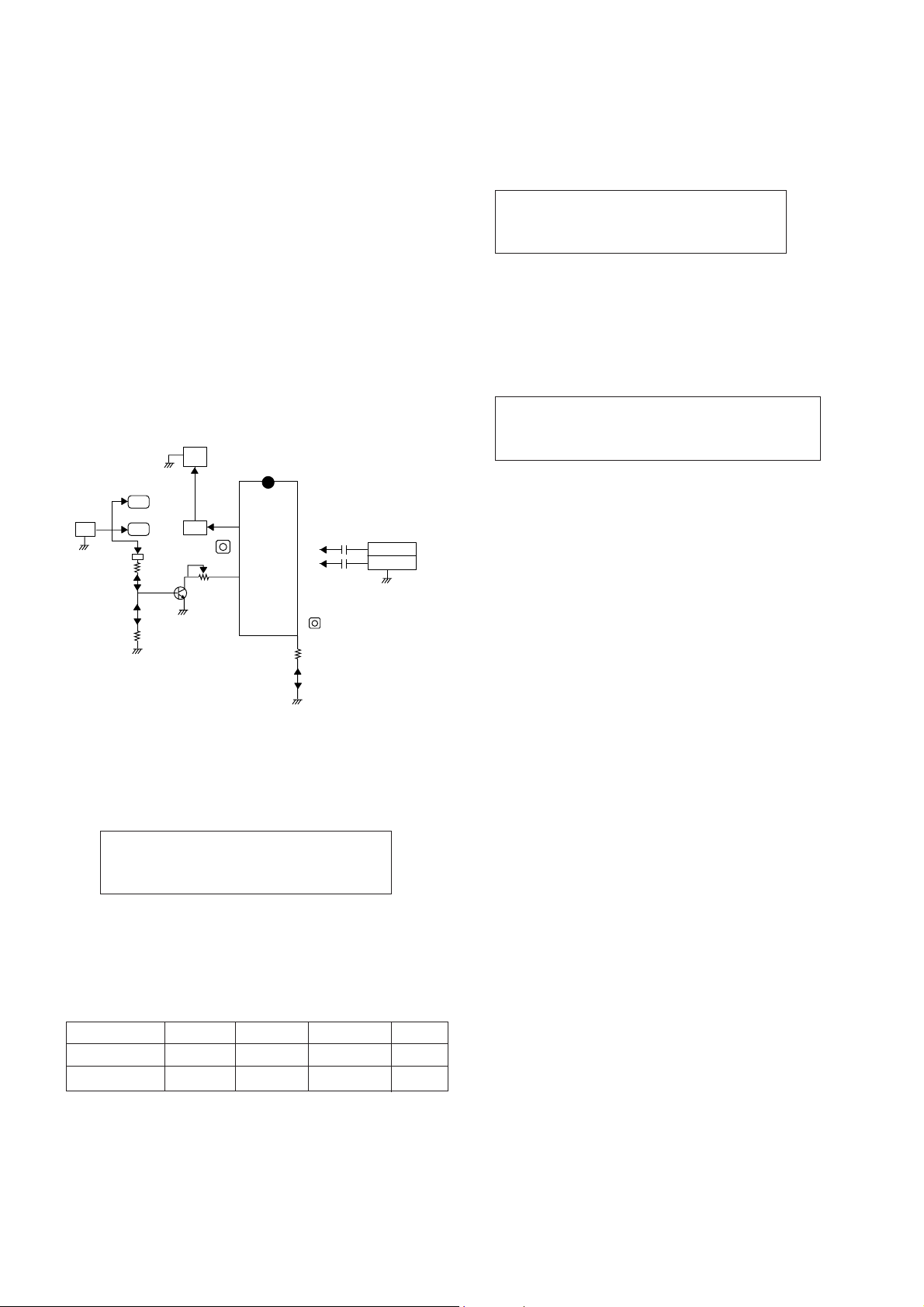
PIF (Picture Intermediate Frequency) Adjustment
1) Connect the measuring equipment to the Main Board as
shown in Fig.1.
2) Set RF frequency and output level of RF SIGNAL
GENERATOR as shown Table 1.
3) Turn off S1 and S3 and on S2.
4) Adjust L107 so that the DC voltage may be 2.5!0.1Vdc.
(Table 1)
O
SECAM-L' Adjustment
NOTE : This adjustment should be performed after PIF
adjustment.
1) Turn on S1 and S3 and off S2.
2) Adjust VR102 so that the DC voltage may be indicated
2.5!0.1Vdc.
O
RF AGC (Automatic Gain Control) Adjustment
The RF AGC control (VR101) was aligned at the time of
manufacture for optimum performance over a wide range
conditions. Readjustment of VR101 should not be necessary
unless unusual local conditions exist, such as ;
1) Channel interference in a CATV system.
2) Picture bending and/or color beats, which are unusually due
to excessive RF signal input when the receiver is too close
to a transmitting tower or when the receiver is connected to
an antenna distribution system where the RF signal has
been amplified. In this case, the input signal should be
attenuated (with pad or filter) to a satisfactory level.
3) Picture noise caused by "broadcast noise" or weak signal.
If the broadcast is "clean" and the RF signal is at least 1mV
(60dBu), the picture will be noise free in any area.
Adjusting the VR101(RF AGC) control to one end of rotation
will usually cause a relatively poor signal to noise ratio;
Adjusting to the other end of rotation will usually cause a
degradation of over load capabilities resulting in color beats or
adjacent channel interference. For best results, adjust the
VR101 control while performing on all over local channels, or
the voltage at TP2 will be 2.3!0.1Vdc in RF level 65!1dBuV.
IC101
TDA4474
TP1
JP7 IC05
IC102
5V
JP3
S1
S3
S2
JP5
Q106
4.7kΩ
100Ω
100Ω
24
7
11
15
VR102
1
0.01pF
SignalGenerator
(B/G,D/K,I,L)
(SECAM-L')
JP1
L107
16
VR102
38.9MHz
34.25MHz
5V
PowerSupply
V Multimeter or Oscilloscope
JP2
JP4
Test Point : TP1
Adjust : L107
Test Point : TP1
Adjust : VR102
Frequency
38.9MHz
34.25MHz
System
B/G,D/K/I,SECAM-L
SECAM-L'
Modulation
OFF
OFF
Output level
10mVp-p
10mVp-p
Adjust
L107
VR102
Main Board(Component side view)
Fig. 1 : Connection Diagram of Equipment for PIF Adjustment
ADJUSTMENT INSTRUCTIONS
Test Point : TP2 (J8) or Observing Display
Adjust : VR101
Page 2
- 2 -
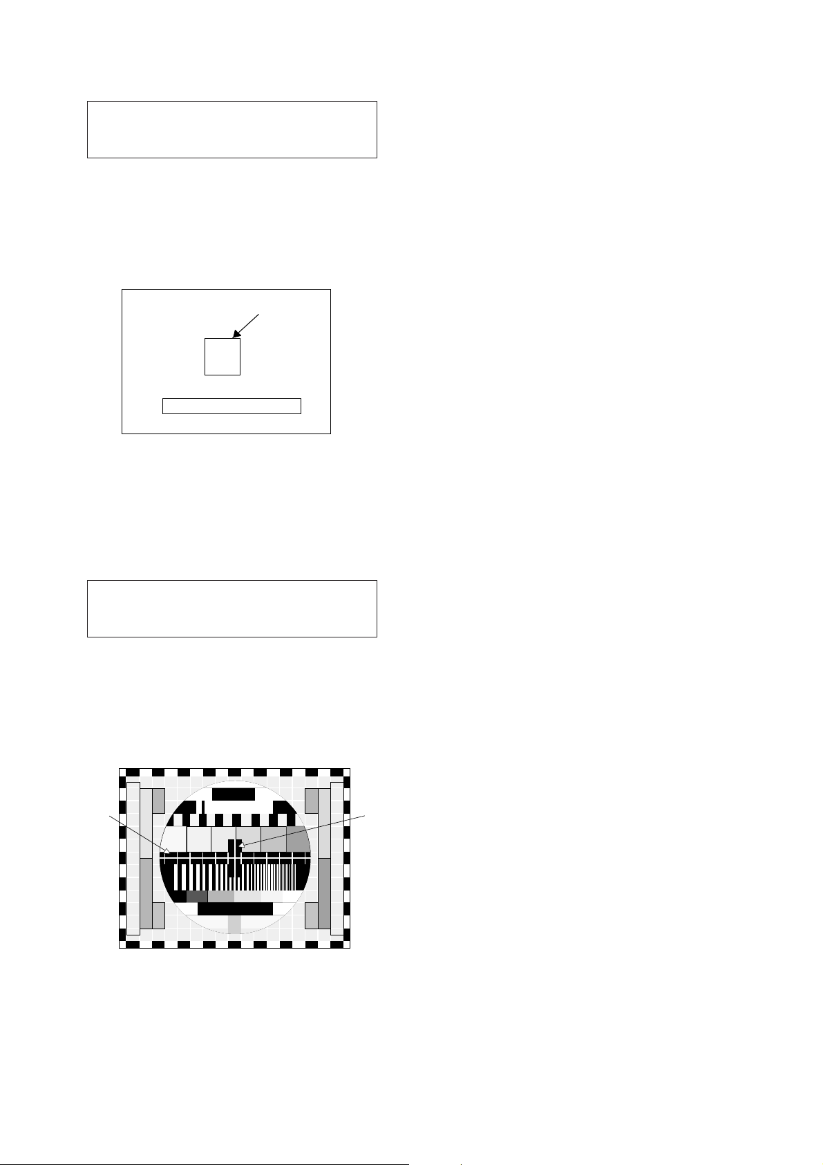
O Screen Voltage Adjustment
1) Tune the TV set to receive a digital pattern.
2) Press MIX button on remote controller for Service to get
into the Screen Adjust Mode.
3) Adhere the Color Analyzer on the White window of CPT
face.
4) Adjust Screen Volume of FBT so that the luminance of
White window is 40!1ft/L.
O
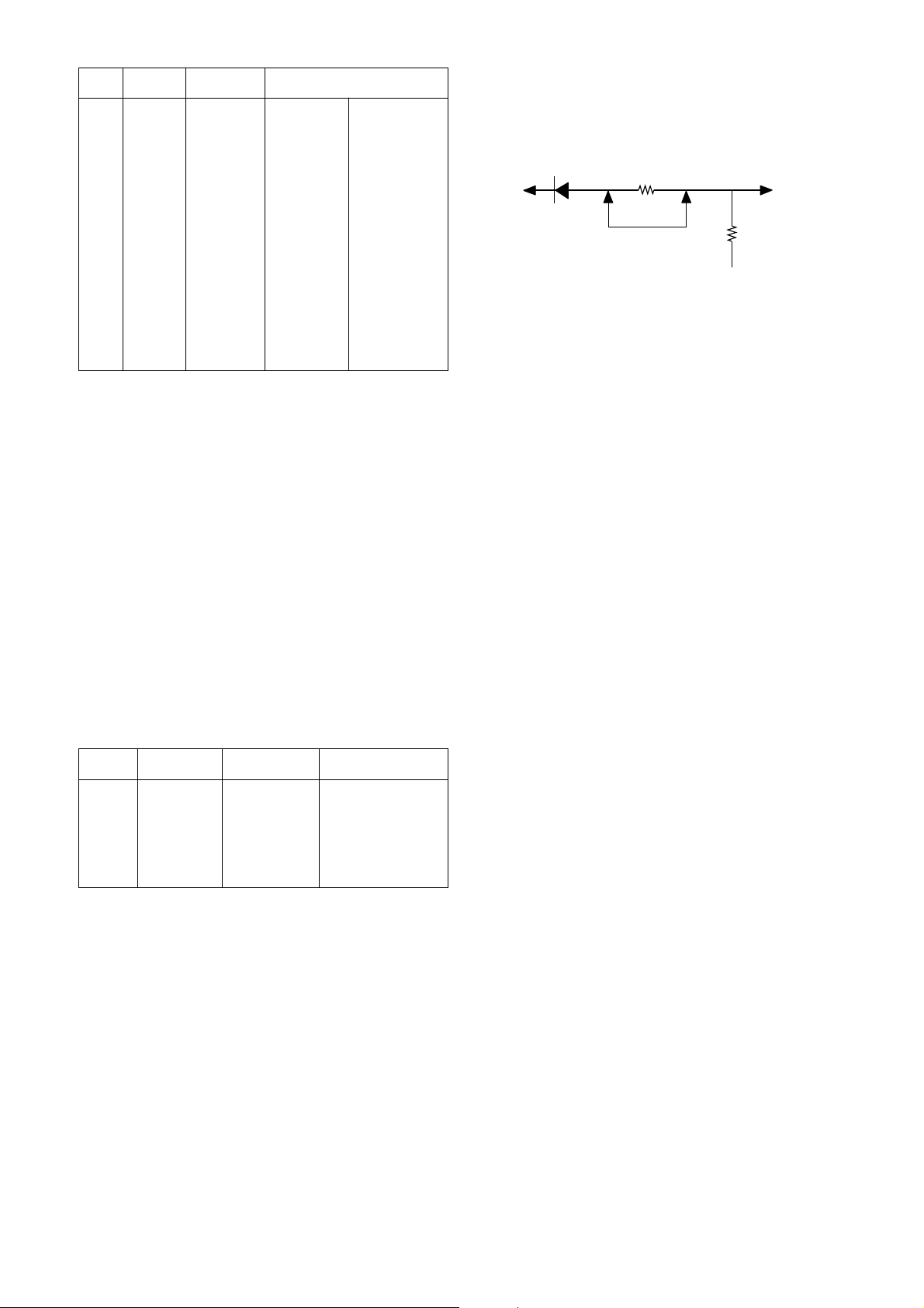
Focus Adjustment
NOTE: This adjustment should be performed after warming
up for 10 minutes.
1) Tune the TV set to receive a digital pattern.
2) Adjust the lower Focus control of FBT for the best focus of
vertical line B.
3) Adjust the upper Focus control of FBT for the best focus of
area A.
4) Repeat above step 2) and 3) for the best overall focus.
O
Deflection Data Adjustment (Line SVC-1)
NOTE: To enter SVC mode, press "OK" buttons on both TV
set and the Remote control at the same time.
1. Preparation for Deflection Adjustment
1) At SVC mode, press the Yellow colored button.
If the Remote Controller doesn't have the Yellow button,
use the button under the Channel Down(PR
U) button.
And then, deflection data adjustment OSD (SVC1 mode)
will be displayed.
2) Press Channel UP/DOWN button for desirous function
Adjustment.
3) Press Volume UP/DOWN button to adjust the data.
VL--(Vertical Linearity)
Adjust so that the boundary line between upper and lower half is
in accord with geometric horizontal center of the CPT.
VH--(Vertical Height)
Adjust so that the circle of a digital circle pattern may be located
within the effective screen of the CPT.
SC--(Vertical "S" correction)
Adjust so that all distance between each horizontal lines are to
be the same.
VS--(Vertical Shift)
Adjust so that the horizontal center line of a digital circle pattern
is in accord with geometric horizontal center of the CPT.
HS--(Horizontal Shift)
Adjust so that the vertical center line of a digital circle pattern is
in accord with geometric vertical center of the CPT.
EW--(Horizontal Width)
Adjust to that a digital circle pattern looks like exact circle.
EP--(East-west Parabola)
Adjust so that middle portion of the outermost left and right
vertical line looks like parallel with vertical lines of the CPT.
EC--(East-west Corner)
Adjust so that the vertical line at every 4 corners of the screen
looks like parallel with the vertical lines of the CPT.
ET--(East-west Trapezium)
Adjust to make the length of top horizontal line same with it of the
bottom horizontal line.
Test Point : RK (Red Cathode of CPT Board)
Adjust : Screen Control of FBT
Test Point : Observing Display
Adjust : Focus control of FBT
Fig. 3
White window OSD
SCREEN ADJUST MODE
Fig. 2 SVC MODE for SCREEN Adjust
A
b
B
Page 3
- 3 -
(Table 2)
O
White Balance Adjustment.(LINE SVC 0)
NOTE : This adjustment should be performed after screen
voltage adjustment.
1) Tune the TV set to receive an 100% white pattern.
2) Press the Yellow button on remote controller in the SVC
Mode (press OK buttons on both TV set and remote
controller at the same time) then you can find On Screen
Display.
3) Press PSM (RED) button on remote controller. (Standard
picture)
4) Press PR+ or PR- button for desirous function adjustment.
5) Adjust VOL+ or VOL- button for Gg31.
6)
Adjust VOL+ or VOL-button in each status of "Rg--"/"Bg--" for
X=272
!
8, Y=295!8 with color analyzer (color temperature
11,000
o
K).
(Table 3)
O
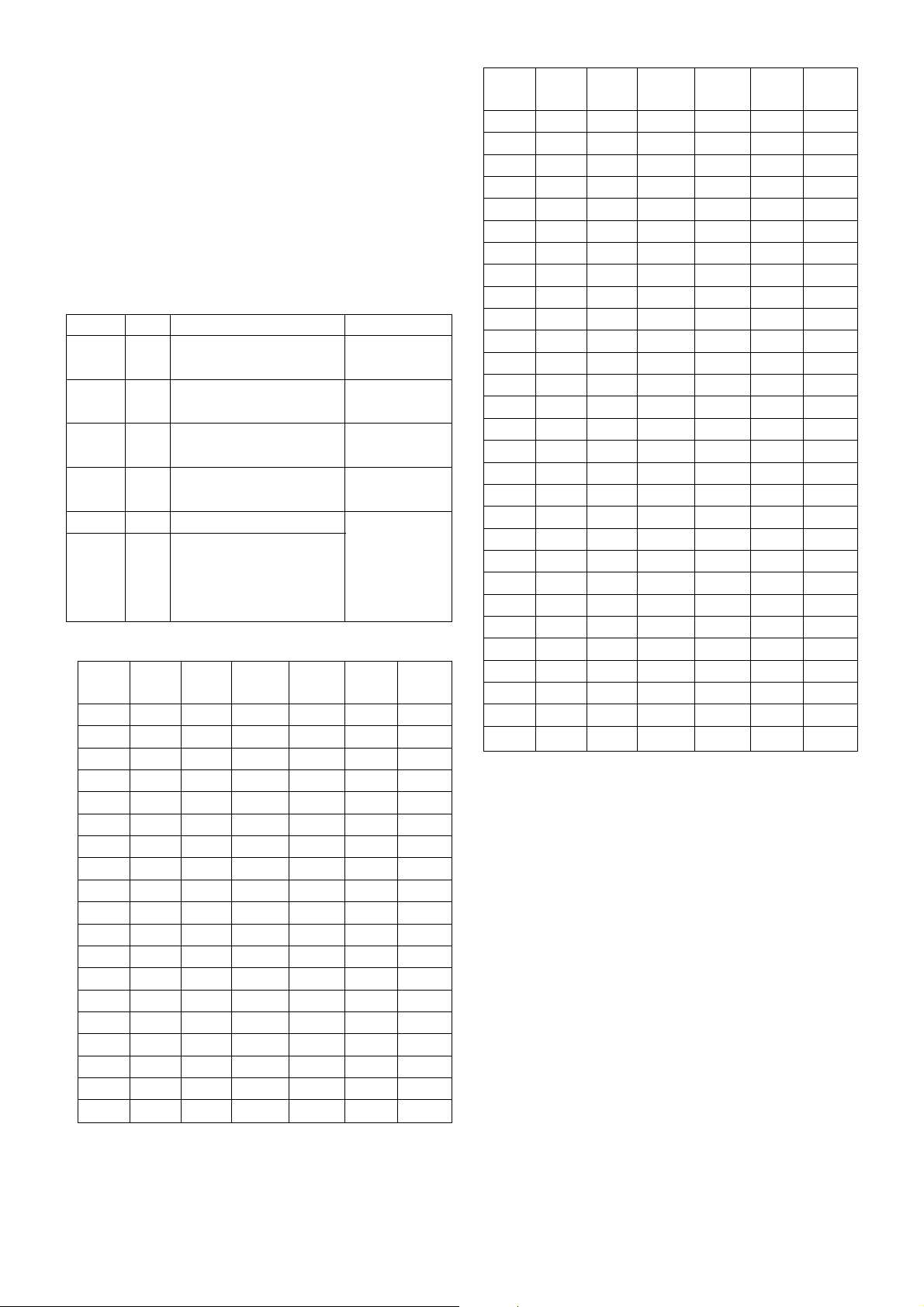
Hold Down Check(X-ray Protection)
1) Short the both terminal of R430 on the Main2 Board and
check if the TV set turns into Stand-by.
Abnormal
D407
R430
Short
FR401
To CPT(HT)
Fig. 4
Menu
VL
VA
SC
VS
HS
EW
EP
EC
ET
VZ
0~63
0~63
0~63
0~63
0~63
0~63
0~63
0~63
0~63
0~63
28
27
16
29
18
37
29
32
30
31
-1
+12
28
26
16
29
30
37
29
32
30
31
Range LG 29” Flat REMARKS(n60Hz)
Menu
RG
GG
BG
Y-dly
0~63
0~63
0~63
0~15
31
31
31
12 15(D/K, I)
Range LG 29” Flat REMARKS
Page 4
O OPTION Adjustment (SVC MODE:OPTION-1,
OPTION-2, OPTION-3)
NOTE: When the EEPROM has been replaced, the Option data
should be restored as the function of individual system
and specification.
1) Press OK buttons on both TV set and Remote Controller at
the same time to get into SVC mode.
2) Press the Yellow button several times to find OPTION-1,
OPTION-2 and OPTION-3.
3) Input the correspond OPTION data referring to Table below
with the numeric buttons 0~9.
Table 1. OPTION 1 Function
Table 2. Specifications for OPTION-1 data
- 4 -
Not available with
SECAM-L/L’
Not available with
NTSC-M
RGB input/Auto AV
Lang1
0
1
0
1
SCART
China
+AU
L-sys
M-sys
Option Code
0
1
0
1
0
1
0
1
Lang0
0
0
1
1
Function Remark
Without NTSC-M
With NTSC-M
Without SECAM-L/L’
With SECAM-L/L’
CCIR CH. Table
China CH. Table
Phono jack(AV1)
Scart jack(AV1)
OSD Language
English Only
English or Arabic/Parsi/
English or Chines
English or Deutsch/Franch/Italiano.Spanish
OPTION
Data
M-sys
L-sys China
SCART
Lang0
0
1
2
3
4
5
6
7
8
9
10
11
12
13
14
15
16
17
18
0
0
0
0
0
0
0
0
0
0
0
0
0
0
0
0
0
0
0
0
0
0
0
0
0
0
0
0
0
0
0
0
0
0
0
1
1
1
0
0
0
0
0
0
0
0
1
1
1
1
1
1
1
1
0
0
0
0
0
0
0
1
1
1
1
0
0
0
0
1
1
1
1
0
0
0
0
1
0
1
0
1
0
1
0
1
0
1
0
1
0
1
0
1
0
Lang1
0
0
1
1
0
0
1
1
0
0
1
1
0
0
1
1
0
0
1
OPTION
Data
M-sys
L-sys China
SCART
Lang0
19
20
21
22
23
24
25
26
27
28
29
30
31
32
33
34
35
36
37
38
39
40
41
42
43
44
45
46
47
0
0
0
0
0
0
0
0
0
0
0
0
0
1
1
1
1
1
1
1
1
1
1
1
1
1
1
1
1
1
1
1
1
1
1
1
1
1
1
1
1
1
0
0
0
0
0
0
0
0
0
0
0
0
0
0
0
0
0
0
0
0
0
1
1
1
1
1
1
1
1
0
0
0
0
0
0
0
0
1
1
1
1
1
1
1
1
0
1
1
1
1
0
0
0
0
1
1
1
1
0
0
0
0
1
1
1
1
0
0
0
0
1
1
1
1
1
0
1
0
1
0
1
0
1
0
1
0
1
0
1
0
1
0
1
0
1
0
1
0
1
0
1
0
1
Lang1
1
0
0
1
1
0
0
1
1
0
0
1
1
0
0
1
1
0
0
1
1
0
0
1
1
0
0
1
1
Page 5
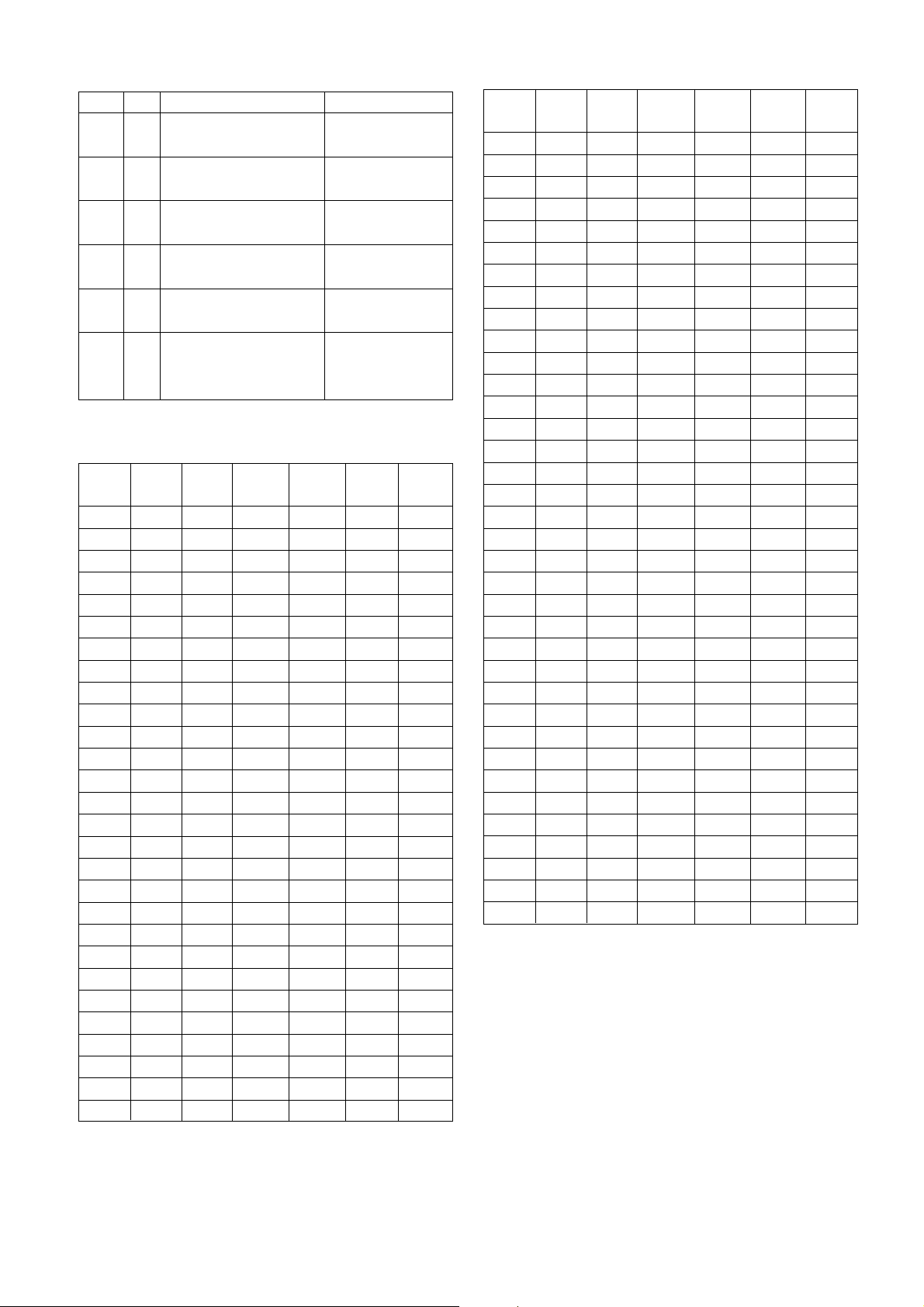
Table 3. OPTION 2 Function
Table 4. Specifications for OPTION-2 data
- 5 -
OPTION
Data
TOP
DCF TILT
EYE
V-curve
0
1
2
3
4
5
6
7
8
9
10
11
12
13
14
15
16
17
18
19
20
21
22
23
24
25
26
27
0
0
0
0
0
0
0
0
0
0
0
0
0
0
0
0
0
0
0
0
0
0
0
0
0
0
0
0
0
0
0
0
0
0
0
0
0
0
0
0
0
0
0
0
1
1
1
1
1
1
1
1
1
1
1
1
0
0
0
0
0
0
0
0
1
1
1
1
1
1
1
1
0
0
0
0
0
0
0
0
1
1
1
1
0
0
0
0
1
1
1
1
0
0
0
0
1
1
1
1
0
0
0
0
1
1
1
1
0
0
0
0
0
1
0
1
0
1
0
1
0
1
0
1
0
1
0
1
0
1
0
1
0
1
0
1
0
1
0
1
Woofer
0
0
1
1
0
0
1
1
0
0
1
1
0
0
1
1
0
0
1
1
0
0
1
1
0
0
1
1
OPTION
Data
TOP
DCF TILT
EYE
V-curve
28
29
30
31
32
33
34
35
36
37
38
39
40
41
42
43
44
45
46
47
48
49
50
51
52
53
54
55
56
57
58
59
60
61
62
63
0
0
0
0
1
1
1
1
1
1
1
1
1
1
1
1
1
1
1
1
1
1
1
1
1
1
1
1
1
1
1
1
1
1
1
1
1
1
1
1
0
0
0
0
0
0
0
0
0
0
0
0
0
0
0
0
1
1
1
1
1
1
1
1
1
1
1
1
1
1
1
1
1
1
1
1
0
0
0
0
0
0
0
0
1
1
1
1
1
1
1
1
0
0
0
0
0
0
0
0
1
1
1
1
1
1
1
1
1
1
1
1
0
0
0
0
1
1
1
1
0
0
0
0
1
1
1
1
0
0
0
0
1
1
1
1
0
0
0
0
1
1
1
1
0
1
0
1
0
1
0
1
0
1
0
1
0
1
0
1
0
1
0
1
0
1
0
1
0
1
0
1
0
1
0
1
0
1
0
1
Woofer
0
0
1
1
0
0
1
1
0
0
1
1
0
0
1
1
0
0
1
1
0
0
1
1
0
0
1
1
0
0
1
1
0
0
1
1
Set to 0 for no TXT
Set to 1 for DCF board
Set to 1 for Degaussing
Coil with TILT
Set to 1 for EYE
module
Set to 0 for Squitter
AMP
Set to 1 for South East
Asia and China
Woofer
EYE
TILT
DCF
TOP
Option Code
0
1
0
1
0
1
0
1
0
1
0
1
Function Remark
Without TOP Teletext
With TOP Teletext
Without DCF(Digital Comb-Filter)
With DCF
Without TILT circuit
With TILT circuit
Without EYE
With EYE
Without Woofer
With Woofer
Normal Volume curve(Europe, CIS)
Rapid Volume curve(South
East Asia, China)
V-
curve
Page 6
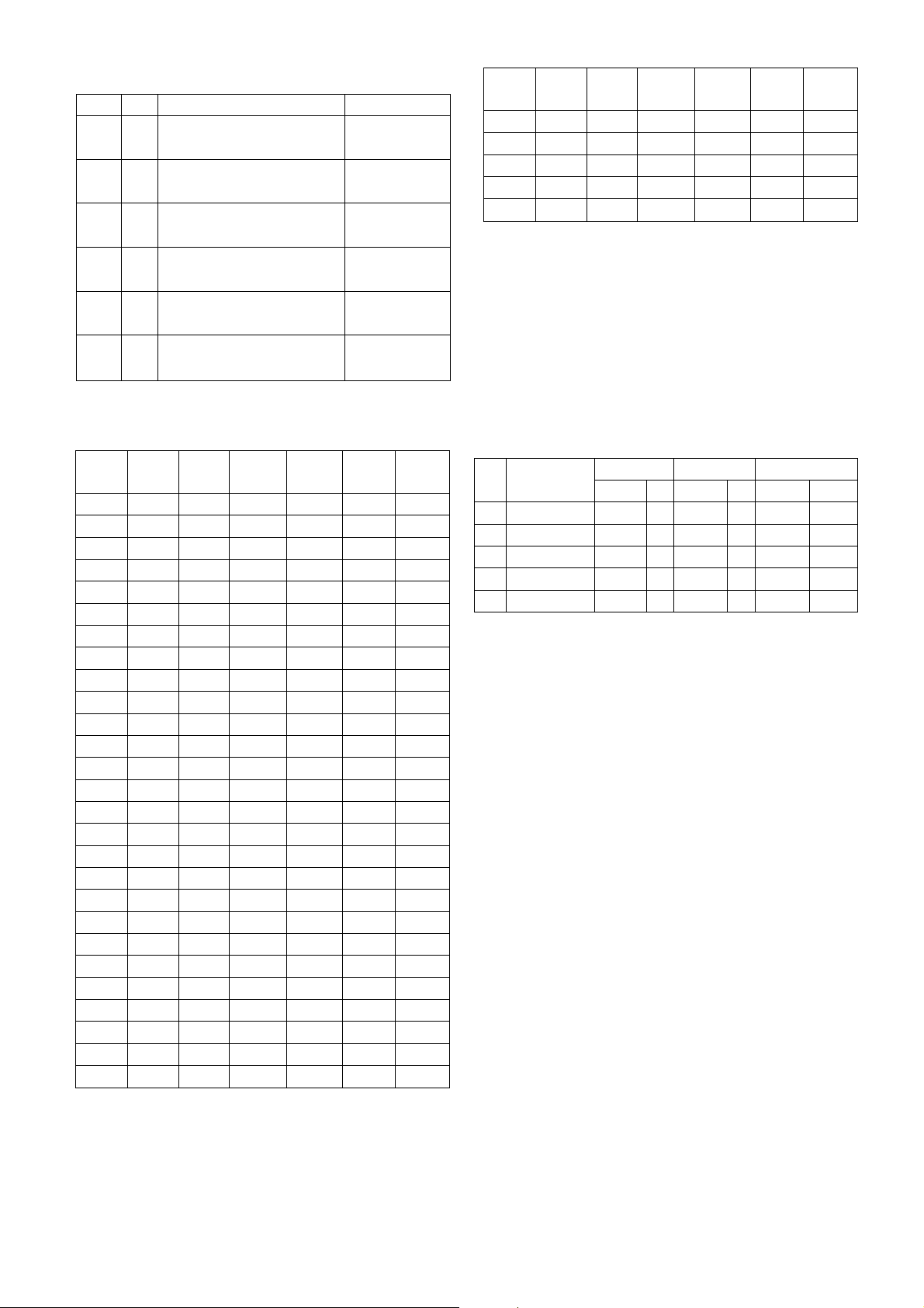
Table 5. OPTION 3 Function
Table 6. Specifications for OPTION-3 data
O Sound Pre scaler
1) Set to Scart when one of AV1 or AV2 is Scart jack.
Audio out level : 500mVrms at 54% modulation ratio
2) Set to Phono when both of AV1 and AV2 is RCA Phono jack.
Audio out level : 500mVrms at 100% modulation ratio.
(NTSC-M : 400mVrms)
[ MSP3410(3400) Pre-scaler setting
- 6 -
OPTION
Data
ACMS
DKNica
m
H-phone
VM
Max.
vol
0, 1
2, 3
4, 5
6, 7
8, 9
10, 11
12, 13
14, 15
16, 17
18, 19
20, 21
22, 23
24, 25
26, 27
28, 29
30, 31
32, 33
34, 35
36, 37
38, 39
40, 41
42, 43
44, 45
46, 47
48, 49
50, 51
52, 53
0
0
0
0
0
0
0
0
0
0
0
0
0
0
0
0
1
1
1
1
1
1
1
1
1
1
1
0
0
0
0
0
0
0
0
1
1
1
1
1
1
1
1
0
0
0
0
0
0
0
0
1
1
1
0
0
0
0
1
1
1
1
0
0
0
0
1
1
1
1
0
0
0
0
1
1
1
1
0
0
0
0
0
1
1
0
0
1
1
0
0
1
1
0
0
1
1
0
0
1
1
0
0
1
1
0
0
1
*
*
*
*
*
*
*
*
*
*
*
*
*
*
*
*
*
*
*
*
*
*
*
*
*
*
*
Hotel
0
1
0
1
0
1
0
1
0
1
0
1
0
1
0
1
0
1
0
1
0
1
0
1
0
1
0
OPTION
Data
ACMS
DKNica
m
H-phone
VM
Max.
vol
54, 55
56, 57
58, 59
60, 61
62, 63
1
1
1
1
1
0
0
1
1
1
1
1
0
0
0
1
1
0
0
1
*
*
*
*
*
Hotel
0
1
0
1
0
Menu
FP
NP
SP
S1 vol
S2 vol
20
85
20
110
110
40
85
20
110
110
FM Pre-scaler
Nicam Pre-scaler
Scart Pre-scaler
Scart1 Pre-scaler
Scart2 Pre-scaler
Description
B/G,D/K,I
Scart Phono SECAM-L/L’ model
M
20
85
47
50
50
40
85
47
50
50
B/G,D/K,I M
20
85
20
110
110
20
85
25
80
80
B/G,D/K,I L/L’
Set to 0 for no
TXT
Set to 1 for
Chinese Model
Set to 1 for H/P jack
Set to 1 for VM
coil magnet
Buyer option
Defalt
Hotel
VM
H-
Phone
DKNic
am
ACMS
Option Code
0
1
0
1
0
1
0
1
0
1
0~
100
Function Remark
Without Auto Channel Memory System
With Auto Channel Memory System
D/K stereo
Without DK stereo
Without H/P jack
With H/P jack
Without VM
With VM
Without Hotel mode
With Hotel mode
Maximum volume level for Hotel
mode data(Normal=36steps)
Max.
vol
Page 7
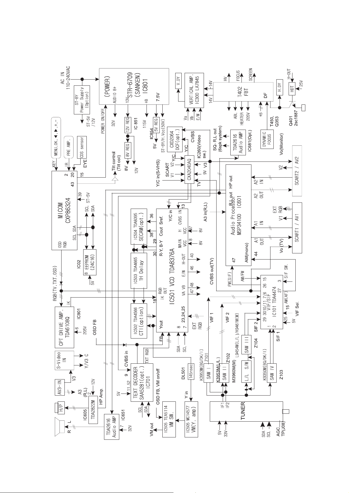
BLOCK DIAGRAM
Page 8

Service Sheet of MC-991A
P/No : 3854VA0052A-S1
Date : 1999.4 .15
Video
Sound
C
Y
Page 9

Service Sheet of MC-991A
P/No : 3854VA0052A-S2
Date : 1999.4 .15
Page 10

PRINTED CIRCUIT BOARD
MAIN
Page 11

MAIN 2
Page 12

CPT
SIDE A/V
DCF
CONTROL
Page 13

- 18 -
REPLACEMENT PARTS LIST
LOCA. NO PART NO DESCRIPTION
D408
D409
D410
D450
D451
D502
D503
D504
D505
D531
D651
D652
D653
D681
D682
D683
D801
D802
D803
D807
D808
D810
D850
D852
D853
D854
D858
D860
D861
D880
D881
D882
D883
D884
D901
D902
D921
D922
D923
D924
D928
D930
D931
D951
D952
D954
D956
D957
D958
D969
D970
D971
LD1101
ZD01
ZD103
0DD414809ED
0DD150009CC
0DD414809ED
0DD100009AQ
0DD100009AQ
0DD414809ED
0DD414809ED
0DD414809ED
0DD181009AB
0DD414809ED
0DD414809ED
0DD181009AB
0DD414809ED
0DD414809ED
0DD414809ED
0DD181009AB
0DD560000AA
0DD150009CE
0DD100009AL
0DD060009AC
0DD100009AM
0DD060009AC
0DD060009AC
0DD060009AC
0DD200009AH
0DD060009AC
0DD414809ED
0DD414809ED
0DD414809ED
0DD060009AC
0DD060009AC
0DD060009AC
0DD060009AC
0DD414809ED
0DD414809ED
0DD414809ED
0DD400309AD
0DR210009AA
0DR210009AA
0DR210009AA
0DD247109AA
0DD247109AA
0DD247109AA
0DD247109AA
0DD247109AA
0DD247109AA
0DD247109AA
0DD247109AA
0DD247109AA
0DD247109AA
0DD150009CC
0DD150009CC
162-002B
0DZ750009AA
0DZ330009BA
DIODE,1N4148 TA
DIODE,RECTIFIER RGP15G,TP(52MM),GI
DIODE,1N4148 TA
DIODE,RP1HV(1)
DIODE,RP1HV(1)
DIODE,1N4148 TA
DIODE,1N4148 TA
DIODE,1N4148 TA
DIODE,SWITCHING CHIP KDS181 85V 300MA KEC
DIODE, 1N4148 TA
DIODE, 1N4148 TA
DIODE,SWITCHING CHIP KDS181 85V 300MA
KEC
DIODE, 1N4148 TA
DIODE, 1N4148 TA
DIODE, 1N4148 TA
DIODE,SWITCHING CHIP KDS181 85V 300MA
DIODE,RECTIFIER D5SB60 BRIDGE (5A/600V)
DIODE,GP15J TP (1.5A/600V) GI
DIODE,EH-1ZV(1)
DIODE,TVR06J 0.6A/600V 250NS TP G.I
DIODE,RECTIFIER EU1ZV(1) TP SANKEN
DIODE,TVR06J 0.6A/600V 250NS TP G.I
DIODE,TVR06J 0.6A/600V 250NS TP G.I
DIODE,TVR06J 0.6A/600V 250NS TP G.I
DIODE,RECTIFIER RU2AMV(1) TP SANKEN
DIODE,TVR06J 0.6A/600V 250NS TP G.I
DIODE,1N4148 TA
DIODE,1N4148 TA
DIODE,1N4148 TA
DIODE,TVR06J 0.6A/600V
DIODE,TVR06J 0.6A/600V
DIODE,TVR06J 0.6A/600V
DIODE,TVR06J 0.6A/600V
DIODE,1N4148 TA
DIODE,1N4148 TA
DIODE,1N4148 TA
DIODE,RECTIFIER IN4003A
DIODE,RECTIFIER BAV21 TP DO-35 200V .
DIODE,RECTIFIER BAV21 TP DO-35 200V .
DIODE,RECTIFIER BAV21 TP DO-35 200V .
DIODE,DETECTOR 1S2471DETECT SW TP
DIODE,DETECTOR 1S2471DETECT SW TP
DIODE,DETECTOR 1S2471DETECT SW TP
DIODE,DETECTOR 1S2471DETECT SW TP
DIODE,DETECTOR 1S2471DETECT SW TP
DIODE,DETECTOR 1S2471DETECT SW TP
DIODE,DETECTOR 1S2471DETECT SW TP
DIODE,DETECTOR 1S2471DETECT SW TP
DIODE,DETECTOR 1S2471DETECT SW TP
DIODE,DETECTOR 1S2471DETECT SW TP
DIODE,RECTIFIER RGP15G,TP(52MM),GI
DIODE,RECTIFIER RGP15G,TP(52MM),GI
DIODE LED ASSY
DIODE ZENER MTZ7.5B,TP(52MM),ROHM
DIODE,ZENER HZT33(TP) HITACHI
LOCA. NO PART NO DESCRIPTION
D851
IC01
IC01
IC01
IC02
ICD02
IC03
IC101
IC260
IC261
IC300
IC330
IC501
IC502
IC503
IC504
IC505
IC506
IC601
IC605
IC606
IC651
IC701
“
“
IC801
IC802
IC850
IC851
IC852
IC853
IC854
IC901
D04
D05
D06
D07
D104
D107
D109
D110
D111
D300
D330
D350
D351
D400
D402
D403
D404
D405
0ISK100300A
0ISO899316B
0ISO899321A
0ISO899324A
0ISG241600A
0ISO206400A
0ISS753300A
0ITF447400A
0ISO204000A
0IKE780900H
0ISA784500A
0IKE455800E
0IPH837600B
0IPH456620A
0IPH466550A
0IPH839520A
0IMO145770E
0ISG511400A
0IIT341000H
0ISG282200A
0ISS753300A
0IPH261600A
0IPH528100F
0IPH528100K
0IPH528100H
0ISK670900A
0ISH123200B
0ISK115000A
0ISH122100A
0IKE780500K
0IKE780800A
0IKE780500K
0IPH610800A
0DD414809ED
0DD414809ED
0DD414809ED
0DD414809ED
0DD414809ED
0DD414809ED
0DD414809ED
0DD859009AA
0DD859009AA
0DD150009CE
0DD247109AA
0DD414809ED
0DD414809ED
0DD011150AA
0DD150009CC
0DD150009CC
0DD150009CC
0DD100009AE
IC,SLA1003 SIP12 BK DIODE MODULE(
IC,LG8993-16B(CXP86441-567S) *ASIA
IC,LG8993-21A(CXP86441-569S) *ASIA
IC,LG8993-24A(CXP86441-571S) *EU
IC,ST24C16 8D EEPROM(16K)
IC,CXD2064Q 48P,QFP BK 4H MULTI D
IC,KA7533Z RESET T0-92 TP 3.3V
IC,TDA4474(VIF)
IC,CXA2040AQ 32P,QFP BK IIC BUS V
IC,KIA78L09BP(AT) 3P 9V,150MA
IC,LA7845 7SIP V/OUT(1.5A)
IC,KIA4558 8DIP DUAL OP AMP
IC,TDA8376A 52P,SDIP BK MULTI VID
IC,TDA4566/V2 18D CTI
IC,TDA4665/V5 16DIP BK 1H DELAY L
IC,TDA8395P/N2 16D SECAM DETECT.
IC,MC14577CP 8D DUAL VIDEO AMP
IC,TEA5114A 16D RGB S/W
IC,MSP3410D 52P,SDIP BK B4-VERSIO
IC,TDA2822M 8D DUAL AUDIO AMP(1W)
IC,KA7533Z RESET T0-92 TP 3.3V
IC,TDA2616 STEREO AMP(20+20W)
IC,SAA5281ZP/E 52P,SDIP BK WEST
IC,SAA5281ZP/K 52P,SDIP BK EAST
IC,SAA5281ZP/H 52P,SDIP BK EAST
IC,STR/S6709 9S SMPS-CNTR
IC,PC123 FY2PHOTO COUPLER
IC,SE115N(LF12) 3P 115V ERROR AMP
IC,PQ12RF21 4P(TO-220) 12V S/W RE
IC,KIA7805PI 3P(TO-220IS) 5V,1A
IC,KIA7808PI 3P(TO-220IS) 1A,8V
IC,KIA7805PI 3P(TO-220IS) 5V,1A
IC,TDA6108JF 9SIP BK VIDEO OUT AM
DIODE,1N4148 TA
DIODE,1N4148 TA
DIODE,1N4148 TA
DIODE,1N4148 TA
DIODE,1N4148 TA
DIODE,1N4148 TA
DIODE,1N4148 TA
DIODE,MA859
DIODE,MA859
DIODE,GP15J TP (1.5A/600V) GI
DIODE,DETECTOR 1S2471DETECT SW TP
DIODE,1N4148 TA
DIODE,1N4148 TA
DIODE,ESC011M-15
DIODE,RECTIFIER RGP15G,TP(52MM),GI
DIODE,RECTIFIER RGP15G,TP(52MM),GI
DIODE,RECTIFIER RGP15G,TP(52MM),GI
DIODE,RECTIFIER RU1A V(1) TP SANKEN
IC
DIODE
The components identified by mark are
critical for safety.
Replace only with part number specified.
Page 14

- 19 -
LOCA. NO PART NO DESCRIPTION
ZD300
ZD301
ZD350
ZD400
ZD501
ZD503
ZD541
ZD564
ZD801
ZD850
ZD921
ZD951
ZD1201
ZD1202
ZD1203
ZD1204
Q01
Q02
Q03
Q04
Q11
Q102
Q103
Q105
Q106
Q107
Q108
Q109
Q150
Q151
Q201
Q203
Q231
Q232
Q242
Q300
Q330
Q331
Q353
Q350
Q351
Q352
Q354
Q400
Q401
Q530
Q531
Q532
Q533
Q534
Q535
Q536
0DZ180009AA
0DZ180009AA
0DZ120009AA
0DZ750009AA
0DZ240009BC
0DZ750009AA
0DZ510009AB
0DZ750009AA
0DZ750009AA
0DZ110009AA
0DZ750009AA
0DZ180009AA
0DZ620009AA
0DZ620009AA
0DZ620009AA
0DZ620009AA
0TR387500AA
0TR102009AG
0TR102009AG
0TR387500AA
0TR150400BA
0TR388109AA
0TR387500AA
0TR103009AG
0TR387500AA
0TR387500AA
0TR387500AA
0TR103009AG
0TR103009AG
0TR103009AG
0TR387500AA
0TR733009AA
0TR150400BA
0TR150400BA
0TR150400BA
0TR945009AA
0TR127409AB
0TR205900AB
0TR471000AA
0TR945009AA
0TR733009AA
0TR945009AA
0TR945009AA
0TR223800AA
0TR188700AA
0TR387500AA
0TR150400BA
0TR102009AG
0TR150400BA
0TR733009AA
0TR733009AA
0TR733009AA
DIODE,ZENER MTZ18B,TP(52MM),ROHM
DIODE,ZENER MTZ18B,TP(52MM),ROHM
DIODE,ZENER MTZ12B 12V 10MA 0.5W
DIODE ZENER MTZ7.5B,TP(52MM),ROHM
DIODE,ZENER MTZ2.4B 2.4V K-ROHM TP
DIODE ZENER MTZ7.5B,TP(52MM),ROHM
DIODE,ZENER MTZ5.1B,TP(52MM),ROHM
DIODE ZENER MTZ7.5B,TP(52MM),ROHM
DIODE ZENER MTZ7.5B,TP(52MM),ROHM
DIODE,ZENER MTZ 11B,TP(52MM),ROHM
DIODE ZENER MTZ7.5B,TP(52MM),ROHM
DIODE,ZENER MTZ18B,TP(52MM),ROHM
DIODE,ZENER MTZ6.2B,TP(52MM),ROHM
DIODE,ZENER MTZ6.2B,TP(52MM),ROHM
DIODE,ZENER MTZ6.2B,TP(52MM),ROHM
DIODE,ZENER MTZ6.2B,TP(52MM),ROHM
CHIP 2SC3875S(ALY) KEC
CHIP KRC102S SOT-23 TP KEC
CHIP KRC102S SOT-23 TP KEC
CHIP 2SC3875S(ALY) KEC
CHIP 2SA1504S(ASY) KEC
KTC3881 CHIP KEC
CHIP 2SC3875S(ALY) KEC
CHIP KRC103S SOT-23
CHIP 2SC3875S(ALY) KEC
CHIP 2SC3875S(ALY) KEC
CHIP 2SC3875S(ALY) KEC
CHIP KRC103S SOT-23 TP KEC
CHIP KRC103S SOT-23 TP KEC
CHIP KRC103S SOT-23 TP KEC
CHIP 2SC3875S(ALY) KEC
KSA733C-Y
CHIP 2SA1504S(ASY) KEC
CHIP 2SA1504S(ASY) KEC
CHIP 2SA1504S(ASY) KEC
KSC945C-Y
KTA1274-Y TO-92L TP KEC
KTD2059-Y TO-220IS KEC
2SC4710 SANYO OTOROLA IBA
KSC945C-Y
KSA733C-Y
KSC945C-Y
KSC945C-Y
KTC2238A-Y
2SD1887 TO-3PML SANYO
CHIP 2SC3875S(ALY) KEC
CHIP 2SA1504S(ASY) KEC
CHIP KRC102S SOT-23 TP KEC
CHIP 2SA1504S(ASY) KEC
KSA733C-Y
KSA733C-Y
KSA733C-Y
LOCA. NO PART NO DESCRIPTION
Q601
Q602
Q603
Q604
Q641
Q642
Q651
Q660
Q661
Q681
Q800
Q850
Q851
Q852
Q853
Q880
Q881
Q901
Q902
Q903
Q904
Q905
Q906
Q907
Q908
Q952
Q953
Q957
Q958
Q1101
Q2909
Q2910
QD1
QD2
QD3
QD4
QD5
QD6
QD6
QD7
QD8
C09
C10
C11
C11
C15
C16
C20
C22
C23
C24
C25
0TR150400BA
0TR150400BA
0TR150400BA
0TR150400BA
0TR387500AA
0TR387500AA
0TR387500AA
0TR150400BA
0TR150400BA
0TR387500AA
0TR209200AB
0TR968000AA
0TR322809AA
0TR945009AA
0TR320209AA
0TR319809AA
0TR322709AA
0TR945009AA
0TR387500AA
0TR150400BA
0TR150400BA
0TR387500AA
0TR387500AA
0TR150400BA
0TR150400BA
0TR320209AA
0TR320209AA
0TR127009AA
0TR322709AA
0TR733009AA
0TR968000AA
0TR223800AA
0TR150400BA
0TR103009AG
0TR150400BA
0TR150400BA
0TR150400BA
0TR150400BA
0TR387500AA
0TR150400BA
0TR387500AA
0CE106DF618
0CE335DK618
0CE476DF618
0CE476DF618
0CE107DD618
0CE227DF618
0CE476DF618
0CC1500K415
0CC1500K415
0CN1010K519
0CN1010K519
CHIP 2SA1504S(ASY) KEC
CHIP 2SA1504S(ASY) KEC
CHIP 2SA1504S(ASY) KEC
CHIP 2SA1504S(ASY) KEC
CHIP 2SC3875S(ALY) KEC
CHIP 2SC3875S(ALY) KEC
CHIP 2SC3875S(ALY) KEC
CHIP 2SA1504S(ASY) KEC
CHIP 2SA1504S(ASY) KEC
CHIP 2SC3875S(ALY) KEC
KTD2092(CU-STICK) TO-220IS KEC
KTA968A-Y KEC
KTC3228-0 TP(KTC2383),KEC
KSC945C-Y
KTC3202-TP-Y (KTC1959)KEC
KTC3198-TP-Y (KTC1815)KEC
KTC3227-Y
KSC945C-Y
CHIP 2SC3875S(ALY) KEC
CHIP 2SA1504S(ASY) KEC
CHIP 2SA1504S(ASY) KEC
CHIP 2SC3875S(ALY) KEC
CHIP 2SC3875S(ALY) KEC
CHIP 2SA1504S(ASY) KEC
CHIP 2SA1504S(ASY) KEC
KTC3202-TP-Y (KTC1959)KEC
KTC3202-TP-Y (KTC1959)KEC
KTA1270-Y (KTA562TM) TP KEC
KTC3227-Y,TP(KTC1627A),KEC
KSA733C-Y
KTA968A-Y KEC
KTC2238A-Y
CHIP 2SA1504S(ASY) KEC
CHIP KRC103S SOT-23 TP KEC
CHIP 2SA1504S(ASY) KEC
CHIP 2SA1504S(ASY) KEC
CHIP 2SA1504S(ASY) KEC
CHIP 2SA1504S(ASY) KEC
CHIP 2SC3875S(ALY) KEC
CHIP 2SA1504S(ASY) KEC
CHIP 2SC3875S(ALY) KEC
10UF STD 16V M
3.3000UF STD 50V M
47UF STD 16V M
47UF STD 16V M
100UF STD 10V M
220UF STD 16V M
47UF STD 16V M
15P 50V J
15P 50V J
100P 50V K
100P 50V K
For Capacitor & Resistors,
the charactors at 2nd and 3rd
digit in the P/No. means as
follows;
CC, CX, CK, CN : Ceramic
CQ : Polyestor
CE : Electrolytic
RD : Carbon Film
RS : Metal Oxide Film
RN : Metal Film
RF : Fusible
TRANSISTOR
CAPACITOR
Page 15

- 20 -
LOCA. NO PART NO DESCRIPTION
C26
C27
C28
C29
C31
C102
C103
C105
C108
C108
C110
C113
C114
C114
C118
C119
C120
C122
C123
C125
C126
C130
C131
C137
C141
C210
C215
C216
C217
C218
C219
C220
C230
C232
C238
C239
C246
C252
C253
C256
C260
C261
C263
C264
C269
C274
C301
C302
C303
C304
C305
C306
C307
C330
0CN1010K519
0CN1010K519
0CN1010K519
0CN1010K519
0CX6200K409
0CE227DD618
0CE476DK618
0CE225DK618
0CE225DK618
0CE476DF618
0CE476DF618
0CE106DF618
0CSZVTA001F
0CSZVTA001C
0CE225DK618
0CQ4742K439
0CE227DD618
0CE107DD618
0CE104DK618
0CN1030F679
0CX4700K409
0CE106DF618
0CE107DD618
0CN1030F679
0CE225DK618
0CE476DF618
0CQ3342K439
0CQ3342K439
0CQ3342K439
0CQ3342K439
0CQ3342K439
0CQ3342K439
0CE106DF618
0CE227DF618
0CE226DF618
0CE226DF618
0CE227DF618
0CE226DF618
0CE226DF618
0CE476DF618
0CE106DF618
0CE106DF618
0CE106DF618
0CE107DF618
0CE336DF618
0CE106DK618
0CN5610K519
0CN2710K519
0CQ8221N519
0CQ6831N509
0CQ3341N401
0CE107DJ618
0CQ1021N519
0CN4710K519
100P 50V K
100P 50V K
100P 50V K
100P 50V K
62P 50V J
220UF STD 10V M
47UF STD 50V M
2.2000UF STD 50V M
2.2000UF STD 50V M
47UF STD16V M *CL-
47UF STD 16V M
10UF STD 16V M
35V 0.68UFK
TAP105K025BRS *CL-
2.2000UF STD 50V M
0.4700UF S 50V J
220UF STD 10V M
100UF STD 10V M
0.1000UF STD 50V M
10000P 16V M
47P 50V J SL TA52
10UF STD 16V M
100UF STD 10V M
10000P 16V M Y
2.2000UF STD 50V M
47UF STD 16V M
0.3300UF S 50V J
0.3300UF S 50V J
0.3300UF S 50V J
0.3300UF S 50V J
0.3300UF S 50V J
0.3300UF S 50V J
10UF STD 16V M
220UF STD 16V M
22UF STD 16V M
22UF STD 16V M
220UF STD 16V M
22UF STD 16V M
22UF STD 16V M
47UF STD 16V M
10UF STD 16V M
10UF STD 16V M
10UF STD 16V M
100UF STD 16V M
33UF STD 16V M
10UF STD 50V M
560P 50V K
270P 50V K
0.0082U 100V K
0.068U 100V K
0.33U 100V J
100UF STD 35V M
0.001U 100V K
470P 50V K
LOCA. NO PART NO DESCRIPTION
C331
C332
C350
C351
C352
C353
C354
C355
C400
C401
C402
C404
C405
C407
C408
C409
C410
C411
C412
C413
C414
C415
C416
C417
C418
C419
C420
C421
C422
C423
C424
C425
C426
C427
C430
C450
C451
C452
C501
C502
C503
C504
C505
C507
C508
C508
C509
C510
C511
C512
C513
C514
C515
C516
0CE107DJ618
0CQ1031N509
0CN1040K949
0CE107DF618
0CQ3342K439
181-064P
0CQ1052K439
0CQ5642K439
0CE474DK618
0CK2220W515
0CE475BP618
181-091W
181-009R
181-015M
181-015M
0CQZVBK004B
181-013N
181-013P
181-013T
0CK2220W515
181-091C
181-091C
0CE1086H618
0CQ1031N509
0CE1086H618
0CQ1031N509
0CK56101515
0CE107DK618
0CK56101515
0CE476DR618
181-009D
0CQ1531N509
0CE5651K652
181-033T
0CE106BR618
0CQ1041N509
181-015K
181-014N
0CQ1042K439
0CE475DK618
0CE105DK618
0CQ1042K439
0CE476DF618
0CQ1042K439
0CE225DK618
0CQ4742K439
0CQ1042K439
0CQ1042K439
0CQ1042K439
0CQ1042K439
0CQ1042K439
0CQ1042K439
0CQ3342K439
0CQ1042K439
100UF STD 35V M
0.01U 100V K
0.1M 50V Z
100UF STD 16V M
0.3300UF S 50V J
CE BP 16V 10 MFTR
1UF S 50V J
0.5600UF S 50V J
0.4700UF STD 50V M
2200P 500V K B
4.7000UF KME 160V M
2KV R 471K TP7.5
PP 200V 0.022UF K
MPP 1600V 0.01UF H
MPP 1600V 0.01UF H
0.027UF D 630V J
MPP 400V 0.27UF J
MPP 400V 0.33UF J
MPP 400V 0.70UF J
2200P 500V K
R 471K 1KV TP5
R 471K 1KV TP5
1000U SMS 25V M
0.01U 100V K
1000U SMS 25V M
0.01U 100V K
560P 1KV K B TS
100UF STD 50V M
560P 1KV K B TS
47UF STD 250V M
PP 200V 0.068UF J
0.015U 100V K
5.6000UF SM 50V M
2KV B 222K TP7.5
10UF KME 250V M
0.1U 100V K
MPP 1600V 0.0091UF H
MPP 1600V 0.01UF J
0.1000UF S 50V J
4.7000UF STD 50V M
1UF STD 50V M
0.1000UF S 50V J
47UF STD 16V M
0.1000UF S 50V J
2.2000UF STD 50V M
0.4700UF S 50V J
0.1000UF S 50V J
0.1000UF S 50V J
0.1000UF S 50V J
0.1000UF S 50V J
0.1000UF S 50V J
0.1000UF S 50V J
0.3300UF S 50V J
0.1000UF S 50V J
For Capacitor & Resistors,
the charactors at 2nd and 3rd
digit in the P/No. means as
follows;
CC, CX, CK, CN : Ceramic
CQ : Polyestor
CE : Electrolytic
RD : Carbon Film
RS : Metal Oxide Film
RN : Metal Film
RF : Fusible
Page 16

- 21 -
LOCA. NO PART NO DESCRIPTION
C517
C520
C520
C521
C523
C524
C525
C526
C528
C529
C530
C531
C532
C533
C541
C546
C547
C549
C550
C557
C557
C559
C560
C561
C563
C565
C569
C570
C572
C577
C588
C605
C607
C607
C611
C616
C617
C619
C621
C622
C623
C627
C630
C632
C632
C637
C642
C649
C650
C655
C655
C656
C656
C662
0CQ1042K439
0CQ1021N509
0CQ4721N509
0CQ1042K439
0CQ2221N509
0CQ4721N509
0CSZVTA001C
0CQ1041N455
0CE107DF618
0CQ1042K439
0CE105DK618
0CE225DK618
0CE225DK618
0CN1040K949
0CE476DF618
0CE476DF618
0CE476DF618
0CQ1042K439
0CQ1042K439
0CE107DF618
0CE337DF618
0CQ4742K439
0CQ4742K439
0CQ4742K439
0CN1040K949
0CE476DF618
0CE476DF618
0CN1040K949
0CN1030F679
0CN3310K519
0CQ3342K439
0CN1030F679
0CE106DF618
0CE107DD618
0CE106DF618
0CE106DF618
0CE106DF618
0CE227DF618
0CE106DF618
0CE107DF618
0CE476DF618
0CQ4742K439
0CQ4742K439
0CE106DF618
0CE335DK618
0CQ6831N509
0CE476DF618
0CE108DJ618
0CE477DK618
0CE474DK618
0CQ1042K439
0CE106DF618
0CQ1042K439
0CE108DJ618
0.1000UF S 50V J
0.001U 100V K
0.0047U 100V K
0.1000UF S 50V J
0.0022U 100V K
0.0047U 100V K
25V 1UF K
0.1000UF 100V J
100UF STD 16V M
0.1000UF S 50V J
1UF STD 50V M
2.2000UF STD 50V M
2.2000UF STD 50V M
0.1M 50V Z
47UF STD 16V M
47UF STD 16V M
47UF STD 16V M
0.1000UF S 50V J
0.1000UF S 50V J
100UF STD 16V M
330UF STD 16V M
0.4700UF S 50V J
0.4700UF S 50V J
0.4700UF S 50V J
0.1M 50V Z
47UF STD 16V M
47UF STD 16V M
0.1M 50V Z
10000P 16V M
330P 50V K
0.3300UF S 50V J
10000P 16V M
10UF STD 16V M
100UF STD 10V M
10UF STD 16V M
10UF STD 16V M
10UF STD 16V M
220UF STD 16V M
10UF STD 16V M
100UF STD 16V M
47UF STD 16V M
0.4700UF S 50V J
0.4700UF S 50V J
10UF STD 16V M
3.3000UF STD 50V M
0.068U 100V K
47UF STD 16V M
1000UF STD 35V M
470UF STD 50V M
0.4700UF STD 50V M
0.1UF S 50V J *CL-,CE-
10UF STD 16V M
0.1UF S 50V J *CL-,CE-
1000UF STD 35V M
LOCA. NO PART NO DESCRIPTION
C663
C664
C665
C667
C669
C670
C671
C674
C677
C678
C679
C680
C681
C683
C683
C684
C684
C686
C691
C694
C697
C701
C703
C704
C706
C707
C708
C709
C711
C713
C801
C802
C803
C804
C805
C806
C807
C807
C808
C809
C810
C811
C812
C813
C814
C815
C820
C850
C851
C852
C853
C854
C855
C856
0CQ1042K439
0CE228DK650
0CE107DH618
0CE225DK618
0CE225DK618
0CQ4742K439
0CE227DD618
0CE107DF618
0CE107DF618
0CE107DF618
0CE227DK618
0CE227DK618
0CQ6831N509
0CE105DK618
0CQ1042K439
0CE474DK618
0CQ1042K439
0CE476DK618
0CE107DF618
0CQ1042K439
0CE476DF618
0CE107DF618
0CX1800K409
0CX8R20K509
0CN1040K949
0CQ1042K439
0CQ1042K439
0CE105DK618
0CE476DF618
0CE476DF618
0CQZVBK002B
0CQZVBK002B
0CQZVBK002B
181-091R
181-091R
0CQZVBK002A
181-001U
181-001Y
181-014W
181-091W
0CE477BF618
0CE227BJ618
0CK4710W515
0CE226BN618
0CK1020K515
181-091C
181-120K
0CQ1041N509
181-091D
181-003D
0CE2276P61A
181-091C
0CE476DN618
0CE1051K636
0.1000UF S 50V J
2200UF STD 50V M
100UF STD 25V M
2.2000UF STD 50V M
2.2000UF STD 50V M
0.4700UF S 50V J
220UF STD 10V M
100UF STD 16V M
100UF STD 16V M
100UF STD 16V M
220UF STD 50V M
220UF STD 50V M
0.068U 100V K
1UF STD 50V M
0.1UF S 50V J *CL-,CE-
0.4700UF STD 50V M
0.1UF S 50V J *CL-,CE-
47UF STD 50V M
100UF STD 16V M
0.1000UF S 50V J
47UF STD 16V M
100UF STD 16V M
18P 50V J
8.2P 50V K
0.1M 50V Z
0.1000UF S 50V J
0.1000UF S 50V J
1UF STD 50V M
47UF STD 16V M
47UF STD 16V M
A.C 275V 0.15UF K
A.C 275V 0.15UF K
A.C 275V 0.15UF K
1KV R 102K TP5
1KV R 102K TP5
A.C 275V 0.1UF M
CE 450V 470UF M
CE 450V 330UF M *CL-,CE-
MPP 2KV 0.0033UF J
2KV R 471K TP7.5
470UF KME 16V M
220U KME 35V M
470PF 500V K
22UF KME 100V M
1000PF 50V K
R 471K 1KV TP5
ACT 4KV E 222M FL10
0.1U 100V K
R 102K 1KV TP5
CE 160V 100UF T
220UF SMS 160V M
R 471K 1KV TP5
47UF STD 100V M
1UF SM 50V M
For Capacitor & Resistors,
the charactors at 2nd and 3rd
digit in the P/No. means as
follows;
CC, CX, CK, CN : Ceramic
CQ : Polyestor
CE : Electrolytic
RD : Carbon Film
RS : Metal Oxide Film
RN : Metal Film
RF : Fusible
The components identified by mark are
critical for safety.
Replace only with part number specified.
Page 17

- 22 -
LOCA. NO PART NO DESCRIPTION
C857
C858
C859
C859
C860
C861
C862
C863
C864
C865
C866
C867
C867
C868
C868
C869
C880
C881
C882
C904
C905
C921
C922
C923
C924
C925
C926
C927
C936
C952
C954
C955
C957
C959
C960
C961
C962
C963
C964
C967
C968
C969
C975
C977
C1105
C1201
C1202
C1203
C1204
C1205
C1206
C1207
C1208
C1209
0CK4710W515
0CE108DF618
0CE108DF618
0CE477DF618
0CE477DF618
0CE337DK618
0CE477DD618
181-091C
0CE228DK650
0CE108DK61A
0CK4710W515
0CE108DD618
0CE108DF618
0CE108DD618
0CE477DD618
0CN1010K519
0CK1020W515
0CK1020W515
0CE477DH618
0CE105DK618
0CE476DF618
0CN1010K519
0CN1010K519
0CN1010K519
0CQZVBK002A
0CE475DR618
0CE106DR618
181-033T
0CE106DF618
0CN1040K949
0CN1040K949
0CN3310K519
0CN2210K519
0CE684DK618
0CC1010K415
0CC1010K415
0CK4720W510
0CK4720W510
0CE106DP618
0CE106DN618
0CE106DN618
0CE106DP618
0CE476DK618
0CK1810W515
0CE475DK618
0CN2210K519
0CN2210K519
0CN2210K519
0CN1040K949
0CN2210K519
0CN4710K519
0CN4710K519
0CN2210K519
0CE475DK618
470PF 500V K
1000UF STD 16V M
1000UF STD 16V M
470UF STD 16V M
470UF STD 16V M
330UF STD 50V M
470UF STD 10V M
R 471K 1KV TP5
2200UF STD 50V M
1000UF STD 50V M
470PF 500V K
1000UF STD 10V M
1000UF STD 16V M
1000UF STD 10V M
470UF STD 10V M
100P 50V K
1000P 500V K
1000P 500V K
470UF STD 25V M
1UF STD 50V M
47UF STD 16V M
100P 50V K
100P 50V K
100P 50V K
A.C 275V 0.1UF M (S=15)
4.7000UF STD 250V M
10UF STD 250V M
2KV B 222K TP7.5
10UF STD 16V M
0.1M 50V Z
0.1M 50V Z
330P 50V K
220P 50V K
0.6800UF STD 50V M
100P 50V J
100P 50V J
4700P 500V K
4700P 500V K
10UF STD 160V M
10UF STD 100V M
10UF STD 100V M
10UF STD 160V M
47UF STD 50V M
180P 500V K
4.7000UF STD 50V M
220P 50V K
220P 50V K
220P 50V K
0.1M 50V Z
220P 50V K
470P 50V K
470P 50V K
220P 50V K
4.7000UF STD 50V M
LOCA. NO PART NO DESCRIPTION
C1210
C1211
CD1
CD4
CD6
CD8
CD9
CD11
CD13
CD18
CD31
CD32
FB201
FB400
FB801
FB803
FB804
FB805
FB850
J171
L4
L201
L204
L504
L507
L509
L690
L921
L953
L1205
L1206
F801
F851
F852
F853
DL501
L02
L03
L104
L105
L106
L107
L108
L109
L110
L113
L114
0CE475DK618
0CN2210K519
0CE476DF618
0CE476DF618
0CE106DF618
0CE476DF618
0CE476DF618
0CE106DF618
0CE476DF618
0CE107DD618
0CN1040K949
0CE476DF618
125-123A
125-022K
125-022K
125-022K
125-022K
125-022K
125-022K
125-022K
125-022K
125-022K
125-022K
125-022K
125-022K
125-022K
125-022K
125-123A
125-022K
125-022K
125-022K
131-098B
131-096D
131-096N
131-096D
150-B02K
0LA0821K119
0LA0561K119
150-C01G
0LA0470K119
0LA0102K139
150-E11G
0LA0102K139
0LA0152K119
0LA0681K119
0LA0102K119
0LA0102K119
4.7000UF STD 50V M
220P 50V K
47UF STD 16V M
47UF STD 16V M
10UF STD 16V M
47UF STD 16V M
47UF STD 16V M
10UF STD 16V M
47UF STD 16V M
100UF STD 10V M
0.1M 50V Z
47UF STD 16V M
CORE (CIRC),FERRITE BFD3565R2F(TAPING)
CORE (CIRC),FERRITE 1UH TAPING
CORE (CIRC),FERRITE 1UH TAPING
CORE (CIRC),FERRITE 1UH TAPING
CORE (CIRC),FERRITE 1UH TAPING
CORE (CIRC),FERRITE 1UH TAPING
CORE (CIRC),FERRITE 1UH TAPING
CORE (CIRC),FERRITE 1UH TAPING
CORE (CIRC),FERRITE 1UH TAPING
CORE (CIRC),FERRITE 1UH TAPING
CORE (CIRC),FERRITE 1UH TAPING
CORE (CIRC),FERRITE 1UH TAPING
CORE (CIRC),FERRITE 1UH TAPING
CORE (CIRC),FERRITE 1UH TAPING
CORE (CIRC),FERRITE 1UH TAPING
CORE (CIRC),FERRITE BFD3565R2F(TAPING)
CORE (CIRC),FERRITE 1UH TAPING
CORE (CIRC),FERRITE 1UH TAPING
CORE (CIRC),FERRITE 1UH TAPING
FUSE,4000MA 250 V 5.2X20 CY/GL SEMK
FUSE,3000MA 125 V 2.5X7.6 CY/CE UL
FUSE,4000MA 125 V 2.5X7.6 CY/CE UL
FUSE,3000MA 125 V 2.5X7.6 CY/CE UL
COIL,L/C FILTER(05W) EQF
INDUCTOR,8.2UH K
INDUCTOR,5.6UH K
COIL,CHOKE 1.0UH A
INDUCTOR,0.47UH K
INDUCTOR,10UH K
COIL,IFT VAR,38.9MHZ(VCO)
INDUCTOR,10UH K
INDUCTOR,15UH K
INDUCTOR,6.8UH K
INDUCTOR,10UH K
INDUCTOR,10UH K
For Capacitor & Resistors,
the charactors at 2nd and 3rd
digit in the P/No. means as
follows;
CC, CX, CK, CN : Ceramic
CQ : Polyestor
CE : Electrolytic
RD : Carbon Film
RS : Metal Oxide Film
RN : Metal Film
RF : Fusible
CORE
FUSE
COIL & TRANSFORMER
The components identified by mark are
critical for safety.
Replace only with part number specified.
Page 18

L115
L215
L231
L232
L233
L234
L235
L236
L237
L238
L241
L242
L243
L244
L245
L246
L247
L248
L301
L302
L401
L402
L403
L450
L501
L502
L503
L541
L542
L561
L562
L601
L602
L603
L606
L608
L610
L680
L681
L682
L701
L702
L703
L850
L851
L1201
L1202
L1203
L1204
LD1
LD2
LD3
LD4
LD6
LD8
LD9
LD10
LD12
T401
T450
T801
T802
T803
T804
P02
P201A
P252A
P501A
P601A
P801A
P802A
P901A
FR400
FR401
FR402
FR403
FR404
FR405
FR850
FR901
FR949
FR984
J48
R02
R10
R16
R19
R23
R26
R28
R31
R37
R38
R40
R42
R43
R43
R46
R47
R48
R49
R52
R54
R56
- 23 -
LOCA. NO PART NO DESCRIPTION
0LA0102K119
0LA0102K119
0LA0102K119
0LA0102K119
0LA0102K119
0LA0102K119
0LA0102K119
0LA0102K119
0LA0102K119
0LA0102K119
0LA0102K119
0LA0102K119
0LA0102K119
0LA0102K119
0LA0102K119
0LA0102K119
0LA0102K119
0LA0102K119
0LA1000K119
0LA1000K119
150-W01A
6140VE0001J
150-717J
150-W01D
0LA0471K119
0LA0102K119
0LA0102K119
0LA0102K119
0LA0102K119
0LA0102K119
0LA0102K119
0LA1000K119
0LA0102K119
0LA0102K119
0LA0102K119
0LA0102K119
0LA0102K119
0LA0102K119
0LA1000K119
0LA1000K119
0LA0102K139
0LA0331K119
0LA0102K139
150-C02F
150-C02F
0LA0472K119
0LA0472K119
0LA0472K119
0LA0472K119
0LA0102K119
0LA0102K119
0LA0222K119
0LA0222K119
0LA0102K119
INDUCTOR,10UH K
INDUCTOR,10UH K
INDUCTOR,10UH K
INDUCTOR,10UH K
INDUCTOR,10UH K
INDUCTOR,10UH K
INDUCTOR,10UH K
INDUCTOR,10UH K
INDUCTOR,10UH K
INDUCTOR,10UH K
INDUCTOR,10UH K
INDUCTOR,10UH K
INDUCTOR,10UH K
INDUCTOR,10UH K
INDUCTOR,10UH K
INDUCTOR,10UH K
INDUCTOR,10UH K
INDUCTOR,10UH K
INDUCTOR,100UH K
INDUCTOR,100UH K
COIL,WIDTH 24UH
COIL,H-LINEARITY 20UH
COIL,CHOKE 560UH (E/W)
COIL,WIDTH 3600UH
INDUCTOR,4.7UH K
INDUCTOR,10UH K
INDUCTOR,10UH K
INDUCTOR,10UH K
INDUCTOR,10UH K
INDUCTOR,10UH K
INDUCTOR,10UH K
INDUCTOR,100UH K
INDUCTOR,10UH K
INDUCTOR,10UH K
INDUCTOR,10UH K
INDUCTOR,10UH K
INDUCTOR,10UH K
INDUCTOR,10UH K
INDUCTOR,100UH K
INDUCTOR,100UH K
INDUCTOR,10UH K
INDUCTOR,3.3UH K
INDUCTOR,10UH K
COIL,CHOKE 82UH
COIL,CHOKE 82UH
INDUCTOR,47UH K
INDUCTOR,47UH K
INDUCTOR,47UH K
INDUCTOR,47UH K
INDUCTOR,10UH K
INDUCTOR,10UH K
INDUCTOR,22UH K
INDUCTOR,22UH K
INDUCTOR,10UH K
LOCA. NO PART NO DESCRIPTION
0LA0222K119
0LA0102K119
0LA0102K119
0LA0102K119
151-C02F
151-E06A
150-F06J
150-F06J
6170VMCA01R
151-D02F
387-A05F
387-B06K
387-812J
387-B10J
387-B08H
387-812L
387-812L
387-A08J
0RS0470K607
180-D02U
0RF0101J607
0RF0470K607
0RF0101K607
0RF0141K607
0RF0470H609
180-D02V
0RF1000H609
0RF0102J607
0RD1000F609
0RD1000F609
0RD1500H609
0RD1002F609
0RD1001F609
0RD1000F609
0RD1003F609
0RD1003F609
0RD4701F609
0RD1000F609
0RD1000F609
0RD1000F609
0RD4701F609
0RD4701F609
0RD4701F609
0RD5600F609
0RD5600F609
0RD5600F609
0RD4700F609
0RD1000F609
0RD1000F609
0RD1000F609
INDUCTOR,22UH K
INDUCTOR,10UH K
INDUCTOR,10UH K
INDUCTOR,10UH K
TRANSFORMER,H-DRIVE,EI-19,BULK
TRANSFORMER,DBF,EER-2834,BULK
COIL,LINE FILTER SQE2930
COIL,LINE FILTER SQE2930
TRANSFORMER,SMPS EER5345 370UH
TRANSFORMER,ST-BY
CONNECTOR ASSY,5P (L=350)
CONNECTOR ASSY,6P(L=600)
CONNECTOR ASSY,YJN250 10P
CONNECTOR ASSY,10P(L=500)
CONNECTOR ASSY,8P SHIELD(450)
CONNECTOR ASSY,YJN250 12P
CONNECTOR ASSY,YJN250 12P
CONNECTOR ASSYY,8P (L=500)
0.47 2W 5% TA62
3.3OHM 2 W 5%
1 1W 5% TA62
0.47 2W 5% TA62
1 2W 5% TA62
1.40 OHM 2 W 5% TA62
0.47 1/2W 5 TA52
3.9 OHM 2 W 5% TA62
100 1/2W 5 TA52
10 1W 5% TA62
100 1/6W 5 TA52
100 1/6W 5 TA52
150 1/2W 5 TA52
10K 1/6W 5 TA52
1.0K 1/6W 5 TA52
100 1/6W 5 TA52
100K 1/6W 5 TA52
100K 1/6W 5 TA52
4.70K 1/6W 5% TA52
100 1/6W 5 TA52
100 1/6W 5 TA52
100 1/6W 5 TA52
4.70K 1/6W 5% TA52
4.70K 1/6W 5% TA52
4.70K 1/6W 5% TA52
560 1/6W 5 TA52
560 1/6W 5 TA52
560 1/6W 5 TA52
470 1/6W 5 TA52
100 1/6W 5 TA52
100 1/6W 5 TA52
100 1/6W 5 TA52
CONNECTOR
RESISTOR
The components identified by mark are
critical for safety.
Replace only with part number specified.
For Capacitor & Resistors,
the charactors at 2nd and 3rd
digit in the P/No. means as
follows;
CC, CX, CK, CN : Ceramic
CQ : Polyestor
CE : Electrolytic
RD : Carbon Film
RS : Metal Oxide Film
RN : Metal Film
RF : Fusible
Page 19

- 24 -
LOCA. NO PART NO DESCRIPTION
R58
R60
R62
R64
R68
R69
R70
R71
R73
R76
R83
R86
R101
R102
R104
R106
R111
R113
R115
R117
R125
R127
R128
R132
R137
R138
R139
R214
R215
R216
R216
R216
R217
R218
R219
R221
R229
R237
R238
R239
R241
R260
R261
R262
R264
R265
R270
R270
R271
R271
R273
R300
R301
R302
0RD1000F609
0RD1000F609
0RD1000F609
0RD1000F609
0RD1001F609
0RD6802F609
0RD1800F609
0RD1001F609
0RD1000F609
0RD1000F609
0RD1002F609
0RD1001F609
0RD1000F609
0RD1000F609
0RD1002F609
0RD1001H609
0RD3601F609
0RD1002F609
0RD1002F609
0RD1001F609
0RD1001F609
0RD1001F609
0RD0102F609
0RD1001F609
0RD4701F609
0RD4701F609
0RD4702F609
0RD1001F609
0RD1001F609
0RD1500F609
0RD2200F609
0RD1800F609
0RD1001F609
0RD1001F609
0RD1001F609
0RD1001F609
0RD0752F609
0RD5101F609
0RD5101F609
0RD0752F609
0RD4700F609
0RD1000F609
0RD1000F609
0RD1000F609
0RD2200F609
0RD0752F609
0RD2200F609
0RD2200F609
0RD1000F609
0RD1000F609
0RD4701F609
0RD1000F609
0RD1000F609
0RN2001F409
100 1/6W 5 TA52
100 1/6W 5 TA52
100 1/6W 5 TA52
100 1/6W 5 TA52
1.0K 1/6W 5 TA52
68K 1/6W 5 TA52
180 1/6W 5 TA52
1.0K 1/6W 5 TA52
100 1/6W 5 TA52
100 1/6W 5 TA52
10K 1/6W 5 TA52
1.0K 1/6W 5 TA52
100 1/6W 5 TA52
100 1/6W 5 TA52
10K 1/6W 5 TA52
1K OHM 1/2 W 5% TA52
3.6K 1/6W 5 TA52
10K 1/6W 5 TA52
10K 1/6W 5 TA52
1K 1/6W 5 TA52
1.0K 1/6W 5 TA52
1.0K 1/6W 5 TA52
10 1/6W 5 TA52
1.0K 1/6W 5 TA52
4.7K 1/6W 5 TA52
4.7K 1/6W 5 TA52
47K 1/6W 5 TA52
1.0K 1/6W 5 TA52
1.0K 1/6W 5 TA52
150 1/6W 5 TA52
220 1/6W 5 TA52 *CE-
180 1/6W 5 TA52
1.0K 1/6W 5 TA52
1.0K 1/6W 5 TA52
1.0K 1/6W 5 TA52
1.0K 1/6W 5 TA52
75 1/6W 5% TA
5.1K 1/6W 5 TA52
5.1K 1/6W 5 TA52
75 1/6W 5% TA
470 1/6W 5 TA52
100 1/6W 5 TA52
100 1/6W 5 TA52
100 1/6W 5 TA52
220 1/6W 5 TA52
75 1/6W 5% TA
220 1/6W 5 TA52
220 1/6W 5 TA52
100 1/6W 5 TA52
100 1/6W 5 TA52
4.70K 1/6W 5% TA52
100 1/6W 5 TA52
100 1/6W 5 TA52
2K 1/6W 1% TA52
LOCA. NO PART NO DESCRIPTION
R303
R304
R305
R307
R308
R309
R310
R311
R314
R315
R316
R330
R331
R332
R333
R334
R335
R336
R337
R338
R339
R340
R341
R342
R350
R351
R352
R353
R354
R355
R356
R357
R358
R359
R360
R361
R362
R363
R400
R401
R402
R403
R404
R405
R406
R407
R408
R409
R410
R411
R412
R414
R415
R416
0RN2001F409
0RD1000F609
0RD0331F609
0RS6800H609
0RS6800H609
0RD4702F609
0RD4701F609
0RD2000F609
0RD2202F609
0RN0221H609
0RN0221H609
0RD1000F609
0RN2702F409
0RN1001F409
0RD2702F609
0RN2701F409
0RN2001F409
0RD1501F609
0RD4700F609
0RD3301F609
0RS0561H609
0RS2701H609
0RS1501H609
0RS1501H609
0RD1003F609
0RD1002F609
0RD3000F609
0RD1303F609
0RD5601F609
0RD3301F609
0RS1801H609
0RD4701F609
0RS1002H609
0RD3002F609
0RD8201F609
0RD1500F609
0RD1001F609
0RD5600F609
0RD1000F609
0RD1001F609
0RD2401H609
0RD0332H609
0RD7501H609
0RS1801H609
0RS0561K607
0RS1500H609
0RS4701H609
0RS2202H609
0RS2702H609
0RS1001H609
0RS1300H609
0RD3303F609
180-B01M
0RS5600K607
2K 1/6W 1% TA52
100 1/6W 5 TA52
3.3 1/6W 5 TA52
680 1/2W 5 TA52
680 1/2W 5 TA52
47K 1/6W 5 TA52
4.70K 1/6W 5% TA52
200 1/6W 5 TA52
22K 1/6W 5 TA52
2.2 1/2W 5 TA52
2.2 1/2W 5 TA52
100 1/6W 5 TA52
27K 1/6W 1% TA52
1K 1/6W 1% TA52
27K 1/6W 5 TA52
2.70K 1/6W 1% TA52
2K 1/6W 1% TA52
1.5K 1/6W 5 TA52
470 1/6W 5 TA52
3.3K 1/6W 5 TA52
5.6 1/2W 5 TA52
2.7K 1/2W 5 TA52
1.5K 1/2W 5 TA52
1.5K 1/2W 5 TA52
100K 1/6W 5 TA52
10K 1/6W 5 TA52
300 1/6W 5 TA52
130K 1/6W 5 TA52
5.6K 1/6W 5 TA52
3.3K 1/6W 5 TA52
1.8K 1/2W 5 TA52
4.70K 1/6W 5% TA52
10K 1/2W 5 TA52
30K 1/6W 5 TA52
8.2K 1/6W 5 TA52
150 1/6W 5 TA52
1.0K 1/6W 5 TA52
560 1/6W 5 TA52
100 1/6W 5 TA52
1.0K 1/6W 5 TA52
2.4K 1/2W 5 TA52
33 1/2W 5 TA52
7.5K 1/2W 5 TA52
1.8K 1/2W 5 TA52
5.60 2W 5% TA62
150 1/2W 5 TA52
4.7K 1/2W 5 TA52
22K 1/2W 5 TA52
27K 1/2W 5 TA52
1.0K 1/2W 5 TA52
130 1/2W 5 TA52
330K 1/6W 5 TA52
RS RECT S 5W 7.5K J
560 2W 5% TA62
For Capacitor & Resistors,
the charactors at 2nd and 3rd
digit in the P/No. means as
follows;
CC, CX, CK, CN : Ceramic
CQ : Polyestor
CE : Electrolytic
RD : Carbon Film
RS : Metal Oxide Film
RN : Metal Film
RF : Fusible
Page 20

- 25 -
LOCA. NO PART NO DESCRIPTION
R417
R418
R450
R451
R452
R453
R454
R455
R456
R457
R458
R459
R501
R502
R503
R508
R509
R510
R511
R512
R516
R518
R519
R521
R523
R524
R525
R526
R528
R528
R541
R550
R575
R576
R579
R601
R602
R613
R633
R634
R638
R659
R674
R694
R695
R705
R801
R801
R802
R803
R804
R805
R806
R807
0RD1203H609
0RD3001F609
0RS4700K607
0RS2202K607
0RS2002K607
0RS2202K607
0RS2202K607
0RS2202K607
0RS0221H609
0RS2702K607
180-C02M
0RS2702K607
0RD2003F609
0RD1000F609
0RD1000F609
0RD1003F609
0RD3901F609
0RD2200F609
0RD2200F609
0RD2200F609
0RD1000F609
0RD3001F609
0RD1200F609
0RD1003F609
0RD2702F609
0RN3902F409
0RD1200F609
0RD1502F609
0RD4700F609
0RD4700F609
0RD1500F609
0RD3001F609
0RD1001F609
0RD1001F609
0RD1001F609
0RD0102F609
0RD1000F609
0RD1001F609
0RD1002F609
0RD0472F609
0RD1001F609
0RD1002F609
0RD0272H609
0RD0272H609
0RD0331F609
0RD1800F609
180-822M
180-822G
0RS2202K607
0RS2202K607
0RD5600F609
0RD4300F609
180-A01D
0RS1000H609
120K 1/2W 5 TA52
3.0K 1/6W 5 TA52
470 2W 5% TA62
22K 2W 5% TA62
20K 2W 5% TA62
22K 2W 5% TA62
22K 2W 5% TA62
22K 2W 5% TA62
2.2 1/2W 5 TA52
27K 2W 5% TA62
5.6KOHM 1/2 W 10%
27K 2W 5% TA62
200K 1/6W 5 TA52
100 1/6W 5 TA52
100 1/6W 5 TA52
100K 1/6W 5 TA52
3.9K 1/6W 5 TA52
220 1/6W 5 TA52
220 1/6W 5 TA52
220 1/6W 5 TA52
100 1/6W 5 TA52
3.0K 1/6W 5 TA52
120 1/6W 5 TA52
100K 1/6W 5 TA52
27K 1/6W 5 TA52
39K 1/6W 1% TA52
120 1/6W 5 TA52
15K 1/6W 5 TA52
470 1/6W 5 TA52
470 1/6W 5 TA52
150 1/6W 5 TA52
3.0K 1/6W 5 TA52
1.0K 1/6W 5 TA52
1.0K 1/6W 5 TA52
1.0K 1/6W 5 TA52
10 1/6W 5 TA52
100 1/6W 5 TA52
1.0K 1/6W 5 TA52
10K 1/6W 5 TA52
47 1/6W 5% TA
1.0K 1/6W 5 TA52
10K 1/6W 5 TA52
27 1/2W 5 TA52
27 1/2W 5 TA52
3.3 1/6W 5 TA52
180 1/6W 5 TA52
RWR 15W 1.0 OHM J PD
10W 2.2OHM J *CL-,CE-
22K 2W 5% TA62
22K 2W 5% TA62
560 1/6W 5 TA52
430 1/6W 5 TA52
RW ROUND G 2W 0.16 J
100 1/2W 5 TA52
LOCA. NO PART NO DESCRIPTION
R808
R809
R810
R811
R812
R813
R814
R815
R816
R817
R818
R820
R850
R851
R852
R853
R854
R855
R856
R857
R858
R859
R860
R862
R862
R863
R864
R880
R881
R882
R901
R903
R919
R921
R922
R923
R925
R926
R927
R928
R929
R931
R936
R939
R940
R941
R942
R943
R944
R945
R947
R948
R951
R952
0RS0152K607
0RS0222K607
0RN0680H609
0RN0680H609
0RS6801H609
0RD2001F609
0RD1001F609
0RD3302F609
0RD1001F609
0RS1002H609
180-C02L
180-C02H
0RD2001F609
0RD6801F609
0RS0472K607
0RS1501H609
0RS1002K607
0RD1002F609
0RD4701F609
0RD4700H609
0RS1300H609
0RD1003H609
0RD4701F609
0RS0182H609
0RS0512H609
0RD4701F609
0RD4702F609
0RS0392H609
0RD4701F609
0RD4702F609
0RD1001F609
0RD2201F609
0RD1000F609
0RD1000F609
0RD1001F609
0RD1000F609
0RD1000F609
0RD1000F609
0RD1501H609
0RD1501H609
0RD1501H609
0RD2204H609
0RS6801H609
0RS6801H609
0RS4701H609
0RS4701H609
0RS1500H609
0RD0331H609
0RS1500H609
0RD0331H609
0RD6802F609
0RD1000F609
0RD3901F609
0RD0222F609
15 2W 5% TA62
22 2W 5% TA62
0.68 1/2W 5 TA52
0.68 1/2W 5 TA52
6.8K 1/2W 5 TA52
2.0K 1/6W 5 TA52
1.0K 1/6W 5 TA52
33K 1/6W 5% TA52
1.0K 1/6W 5 TA52
10K 1/2W 5 TA52
0.47MOHM 1/2 W 10%
RC 1/2W 8.2M K TA)
2.0K 1/6W 5 TA52
6.8K 1/6W 5 TA52
47 2W 5% TA62
1.5K 1/2W 5 TA52
10K 2W 5% TA62
10K 1/6W 5 TA52
4.70K 1/6W 5% TA52
470 1/2W 5% TA52
130 1/2W 5 TA52
100K 1/2W 5 TA52
4.70K 1/6W 5% TA52
18 1/2W 5 TA52
51 1/2W 5 TA52 *CL-
4.70K 1/6W 5% TA52
47K 1/6W 5 TA52
39 1/2W 5
4.70K 1/6W 5% TA52
47K 1/6W 5 TA52
1.0K 1/6W 5 TA52
2.2K 1/6W 5 TA52
100 1/6W 5 TA52
100 1/6W 5 TA52
1.0K 1/6W 5 TA52
100 1/6W 5 TA52
100 1/6W 5 TA52
100 1/6W 5 TA52
1.5K 1/2W 5 TA52
1.5K 1/2W 5 TA52
1.5K 1/2W 5 TA52
2.2M 1/2W 5 TA52
6.8K 1/2W 5 TA52
6.8K 1/2W 5 TA52
4.7K 1/2W 5 TA52
4.7K 1/2W 5 TA52
150 1/2W 5 TA52
3.3 1/2W 5 TA52
150 1/2W 5 TA52
3.3 1/2W 5 TA52
68K 1/6W 5 TA52
100 1/6W 5 TA52
3.9K 1/6W 5 TA52
22 1/6W 5 TA52
For Capacitor & Resistors,
the charactors at 2nd and 3rd
digit in the P/No. means as
follows;
CC, CX, CK, CN : Ceramic
CQ : Polyestor
CE : Electrolytic
RD : Carbon Film
RS : Metal Oxide Film
RN : Metal Film
RF : Fusible
The components identified by mark are
critical for safety.
Replace only with part number specified.
Page 21

- 26 -
LOCA. NO PART NO DESCRIPTION
R955
R956
R957
R959
R960
R964
R965
R966
R968
R970
R971
R972
R972
R979
R980
R981
R982
R983
R990
R996
R997
R1101
R1102
R1103
R1204
R1206
R1208
R1212
R1292
RD4
RD19
RD22
VR101
VR102
SG901
SG902
SG903
SG904
JA01
SK101
“
SK102
SK102
SW1
SW2
SW3
SW4
SW5
0RD1201F609
0RD1000F609
0RD1000F609
0RD2201F609
0RD4300H609
0RD1001F609
0RD1202F609
0RD2701F609
0RD6802F609
0RD3300F609
0RD1800F609
0RD3300F609
0RD6200H609
0RD2200F609
0RD1000F609
0RD2200F609
0RD0822F609
0RD0822F609
0RD2701F609
0RD6800H609
0RD6800H609
0RD3300F609
0RD4701F609
0RD1301F609
0RD2403F609
0RD0752F609
0RD2403F609
0RD0752F609
0RD0752F609
0RD4701F609
0RD2201F609
0RD4701F609
180-F03H
180-F03H
165-004A
165-004A
165-004A
165-004A
6613V00004A
6612VMH001A
6612VJH011C
6612VJH011C
6612VMH001A
140-315C
140-315C
140-315C
140-315C
140-315C
1.2K 1/6W 5 TA52
100 1/6W 5 TA52
100 1/6W 5 TA52
2.2K 1/6W 5 TA52
430 1/2W 5 TA52
1.0K 1/6W 5 TA52
12K 1/6W 5 TA52
2.7K 1/6W 5 TA52
68K 1/6W 5 TA52
330 1/6W 5 TA52
180 1/6W 5 TA52
330 1/6W 5 TA52
620 1/2W 5 TA52
220 1/6W 5 TA52
100 1/6W 5 TA52
220 1/6W 5 TA52
82 1/6W 5% TA
82 1/6W 5% TA
2.7K 1/6W 5 TA52
680 1/2W 5 TA52
680 1/2W 5 TA52
330 1/6W 5 TA52
4.70K 1/6W 5% TA52
1.3K 1/6W 5 TA52
240K 1/6W 5 TA52
75 1/6W 5% TA
240K 1/6W 5 TA52
75 1/6W 5% TA
75 1/6W 5% TA
4.70K 1/6W 5% TA52
2.2K 1/6W 5 TA52
4.70K 1/6W 5% TA52
EVN-DJAY03 B103
EVN-DJAY03 B103
SPARK GAP,AG20PT 152F-L3N/S-23
SPARK GAP,AG20PT 152F-L3N/S-23
SPARK GAP,AG20PT 152F-L3N/S-23
SPARK GAP,AG20PT 152F-L3N/S-23
JACK ASSY PJ6054A EARPHONE+S-VHS+3P
JACK,SCART UPJ-R1-018 RGB 21 PI
JACK,RCA PPJ109C A/V IN/OUT 6
JACK,RCA PPJ109C A/V IN/OUT 6
JACK,SCART UPJ-R1-018
SWITCH,TACT
SWITCH,TACT
SWITCH,TACT
SWITCH,TACT
SWITCH,TACT
LOCA. NO PART NO DESCRIPTION
SW6
SW801
LD02
T801
T802
X01
X501
X502
X601
X701
Z101
Z102
Z102
Z103
Z104
Z106
Z109
Z111
Z113
Z210
Z601
A1
A1
A1
A1
A1
A1
A2
A2
A3
P901
RL801
RL802
T402
TH801
TU01
TU01
ZN1101
140-315C
6600VM2001A
150-B02Q
150-F06T
150-F06T
156-A01P
156-A01V
156-A01C
156-A02M
156-A02U
166-A01B
6200VQS001F
166-A01B
6200VQS001G
6200VQS001H
166-C06D
166-F01H
166-F01H
166-F01D
166-C04C
166-F01D
3828VA0180C
3828VA0180G
3828VA0180J
3828VA0191A
3828VA0191J
3828VA0191M
6710V00009M
6710V00009S
450-018C
6212VBK001A
6620VBD001A
141-018F
141-018F
6174Z-6005D
163-054F
6700VPF005B
6700VPF005A
164-003D
SWITCH,TACT
SWITCH,PUSH POWER SDDFC3
FILTER(CIRC),LC LPF 2EA 0.1MHZ
FILTER(CIRC),LINE SQE3535 SMPC 20MH
FILTER(CIRC),LINE SQE3535 SMPC 20MH
CRYSTAL,STANDARD HC49U 8.000MHZ 30
CRYSTAL,STANDARD HC49U 4.433619MHZ 3
CRYSTAL,STANDARD HC49U 3.579545MHZ 3
CRYSTAL,STANDARD HC49U 18.432MHZ 30P
CRYSTAL,STANDARD HC49U 27.000MHZ 30P
FILTER,OFWK3953M 37.4MHZ(PIF
FILTER(CIRC),SAW OFWM3960M 38.9MHZ(INT
FILTER,0FWK3953M *CL-
FILTER(CIRC),SAW 0FWK9350M 38.9MHZ
FILTER(CIRC),SAW OFWK9461M 33.9MHZ(SIF
FILTER(CIRC),TRAP MKT40.4MA110P-TF01
FILTER(CIRC),EMI DS306-93Y5S 101M 50V
FILTER(CIRC),EMI DS306-93Y5S 101M 50V
FILTER,DSS306-93Y5S271M *CL-
FILTER(CIRC),TRAP TPWA02B-TF21 5.5/6.0MHZ
FILTER,DSS306-93Y5S271M MURATA 50VOLT
MANUAL,OWNERS MC991A.LG AR 9MTX
MANUAL,OWNERS MC991A.LG EN 9MTX
MANUAL,OWNERS MC991A.LG RU 9MTX
MANUAL,OWNERS MC991A.DG,LG ,CE/EN
MANUAL,OWNERS MC991A.FS,LG,FR
MANUAL,OWNERS MC991A.PL,LG,PL/EN
REMOTE CONTROLLER(W/TXT,EYE,STEREO)
REMOTE CONTROLLER(W/O TXT,W/EYE,STEREO)
ADAPTER,ANT(300 TO 75)
RESONATOR,JT B455ET4 CHEQUERS 455HZ
SOCKET (CIRC),CPT PCS701A 9P
RELAY,DG5D1-0-2 DAIICHI 5V 106MA 250
RELAY,DG5D1-0-2 DAIICHI 5V 106MA 250
FBT FTMPC31-6005D
THERMISTOR,PTC J502P84D140M290Q
TUNER,TU8PSD01DA LGEC PAL DIN D/K 38
TUNER,TU8PSD01DB
VARISTOR,SVC 561D-14A
For Capacitor & Resistors,
the charactors at 2nd and 3rd
digit in the P/No. means as
follows;
CC, CX, CK, CN : Ceramic
CQ : Polyestor
CE : Electrolytic
RD : Carbon Film
RS : Metal Oxide Film
RN : Metal Film
RF : Fusible
SPARK GAP
JACK
SWITCH
FILTER & CRYSTAL
MISCELLANEOUS
ACCESSORIES
The components identified by mark are
critical for safety.
Replace only with part number specified.
Page 22

112
102
913
150
153
510
170
400
943
300
530
520
550
P801
310
320
330
600
121
125
120
124
700
503
501
540
123
126
EXPLODED VIEW
- 1 -
Page 23

- 2 -
EXPLODED VIEW PARTS LIST
LOCA. NO PART NO DESCRIPTIONS
102 341-919C HOLDER,D-COIL
112 6341V29006A BARE CPT ASSY
6341V29004A BARE CPT ASSY
120 6400VA0015A SPEAKER,GENERAL C151PX-373K14 8 OHM 15W
121 120-C76G SPEAKER,TWEETER C050TX-357K14 8 OHM 10/
123 6400VA0016A SPEAKER,GENERAL C050TX-346K14 8 OHM 15W
124 3550V00039A COVER,SPEAKER
125 4810V00129A BRACKET(R),SPEAKER
126 4810V00129B BRACKET(L),SPEAKER
150 150-201S COIL,DEGAUSSING CU 29” 440TURN 102 OHM 3P
153 6150Z-1240F DY,DC29SLFL1
170 170-844K CPT EARTH
300 3091V00173B CABINET ASSY *CT-29Q10ET
3091V00173L CABINET ASSY *CL-29Q10ET
3091V00173Q CABINET ASSY *CE-29Q10ET
310 5020V00316A BUTTON,CONTROL
320 320-070G SPRING,COIL
330 5020V00315A BUTTON,POWER
400
3809V00127B BACK COVER ASSY
3809V00127J BACK COVER ASSY(2 SCART)
501 4810V00139B BRACKET,MAIN
503
3500V00018A BOARD,A/V(1PHONE & 1SCART)
3500V00017A BOARD,A/V(2SCART)
510 6871VSM327A PWB ASSY,CPT
6871VMM282B PWB ASSY MAIN *LGEMT,LGEIN
6871VMM282C PWB ASSY MAIN *LGEAK,NAGHI,E.A.C
520 6871VMM282D PWB ASSY MAIN *LGEIL
6871VMM282F PWB ASSY MAIN *LGESA,LGEAL,N.ALLIED,H.POINT
6871VMM282G PWB ASSY MAIN *TELESTAR,LGEGF,KOOHEJI,I.G.I
6871VMM282K PWB ASSY MAIN *LGESV
6871VMM333A PWB ASSY MAIN CE,PAL/SECAM *LGEDG,LGEIS,LGEES,AGON
6871VMM333B PWB ASSY MAIN CE,PAL/SECAM *LGEPL
6871VMM335A PWB ASSY MAIN SECAML/L’ *LGEFS
530 6871VDM068B PWB ASSY MAIN2 NON EU(WIDE ST-B
6871VDM082A PWB ASSY MAIN2 CE,PAL/SECAM
6871VDM083A PWB ASSY MAIN2 SECAM(L/L’)
540 6871VSM326A PWB ASSY,DCF
550 6871VSM345A PWB ASSY,CONTROL
600 6871VSM328A PWB ASSY,AV
6871VSM328B PWB ASSY,AV EU
700 0IGL120104D CDS SENSOR MODULE
913 332-229H SCREW ASSY,HEXAGON HEAD
943 1PTF0403116 SCREW,TRUSS HEAD D4.0 L16.0
P801 174-009V CORD,POWER(W/HOLD,HOUSING)
174-224A CORD,POWER FOR UK
The components identified by mark is
critical for safety.
Replace only with part number specified.
 Loading...