

LG 26LV2500, 32LV3500, 42LV3500, 32LV2500, 47LV3500 Owner's Manual
...
eLG
Life's
Good
'.
OWNER'S
MANUAL
LED LCD
PLASMA
Please
set
LED LCD
19LV2500
22LV2500
26LV2500
32LV2500
19LV2520
22LV2520
26LV2520
P/NO:
PrintedinMexico
read
and
retainitfor
TV
MFL62882741
this
manual
MODELS
32LV3500
37LV3500
42LV3500
47LV3500
55LV3500
32LV3520
42LV3520
(llOl-REV04)
future
TV
TV
carefully
reference.
LCD
TV
26LK330
32LK330
32LK430
42LK430
before
MODELS
32LK450
37LK450
42LK450
47LK450
42LK520
47LK520
55LK520
/ LCD
operating
the
PLASMA
42PW340
50PW340
42PW350
50PW350
50PZ200
60PZ200
TV
TV
MODELS
42PW350U
50PW350U
42PW350R
50PW350R
www.lg.com
/
2
IMPORTANT
SAFETY
INSTRUCTIONS
IMPORTANT
Always comply
of
your product.
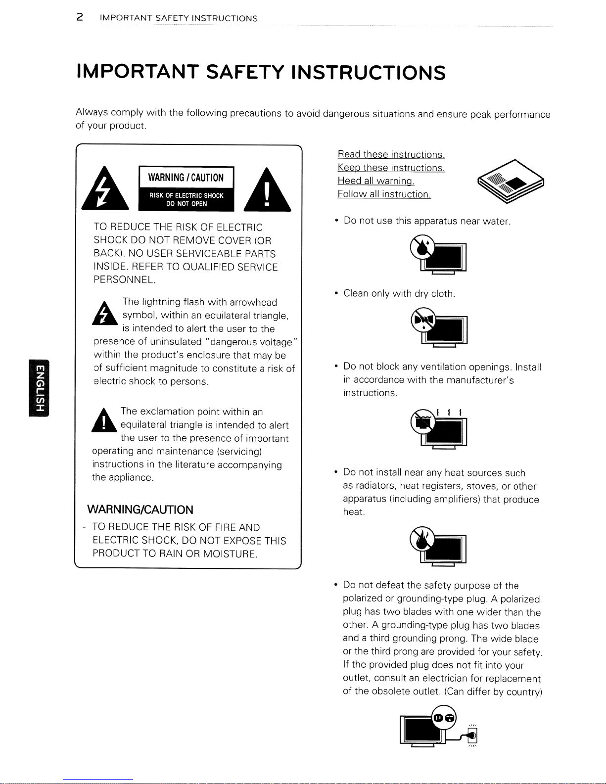
TO
REDUCE THE
SHOCK DO NOT REMOVE
BACK).
INSIDE.
PERSONNEL.
A.
~
presence
within the product's enclosure that may be
of
sufficient magnitude to constitute a risk
electric shock to persons.
with
the following precautions to avoid dangerous situations
NO
USER
REFERTOQUALIFIED
The lightning flash
symbol, withinanequilateral triangle.
is
intended to alert the user to the
of
uninsulated "dangerous voltage"
SAFETY INSTRUCTIONS
RISKOFELECTRIC
COVER
SERVICEABLE
SERVICE
with
arrowhead
(OR
PARTS
of
and
ensure peak performance
Read
these instructions.
Keep
these instructions.
all
Heed
Follow
• Do not use this apparatus near water.
• Clean only
Do
•
in
instructions.
warning.
all
instruction.
with
dry cloth.
not block any ventilation openings. Install
accordance with the manufacturer's
I
A The exclamation point within
....
WARNING/CAUTION
-
equilateral triangleisintended to alert
to
the user
operating and maintenance (servicing)
instructions
the appliance.
TO
REDUCE THE
ELECTRIC SHOCK, DO NOT
PRODUCT
the presence of important
in
the literature accompanying
RISKOFFIRE
EXPOSE
TO
RAIN
OR
MOISTURE.
AND
an
THIS
• Do not install near any heat sources such
as
radiators. heat registers, stoves, or other
apparatus (including amplifiers) that produce
heat.
Do
not defeat the safety purpose of the
•
polarized or grounding-type plug. A polarized
two
plug has
other. A grounding-type plug
and a third grounding prong. The wide blade
or the third prong
If the provided plug does not
outlet. consult
of
the obsolete outlet.
blades
with
one wider than the
has
two
are
provided for your safety.
fit
into your
an
electrician for replacement
(Can
differ by country)
blades
.........................................
IMPORTANT
SAFETY
INSTRUCTIONS
3
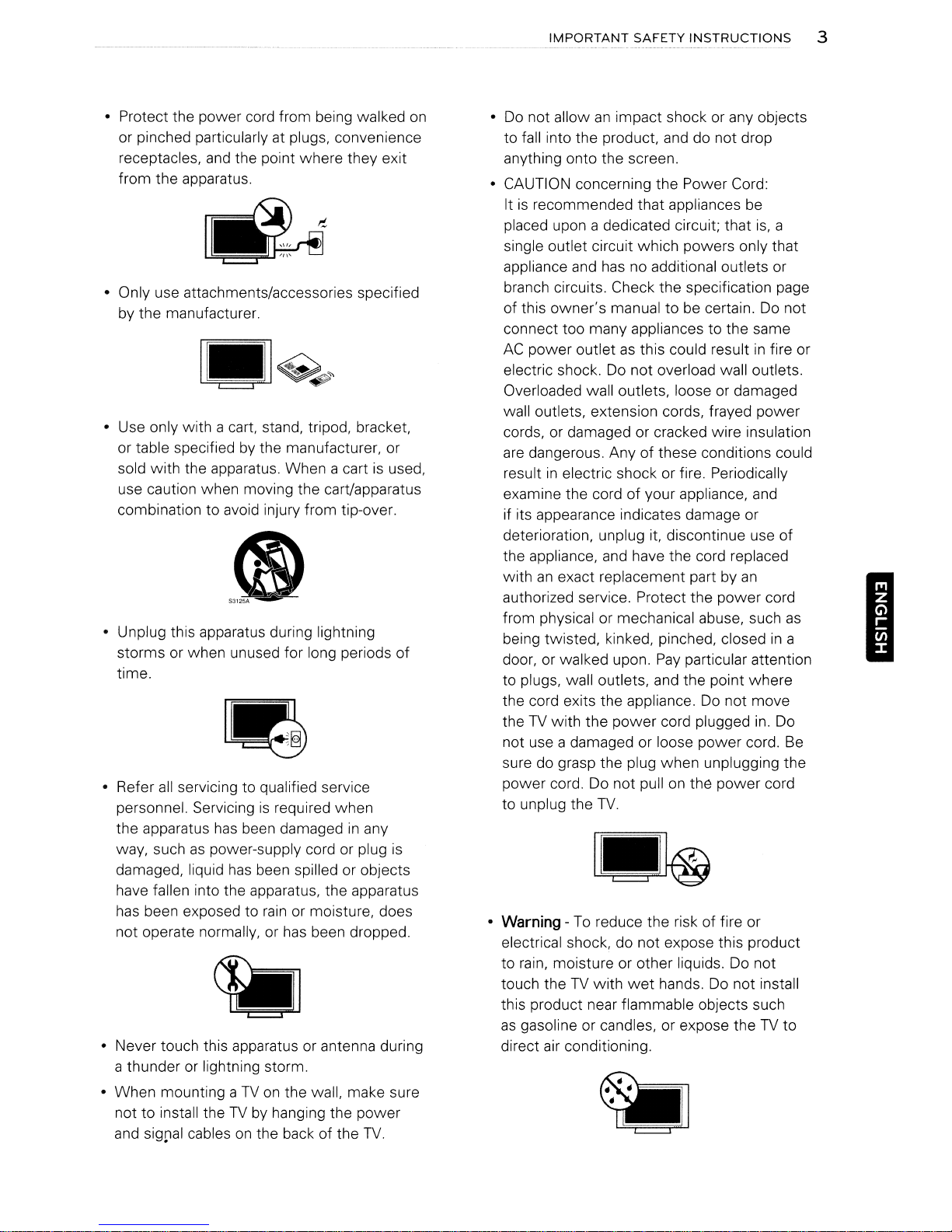
• Protect the power cord from being walked
on
or pinched particularly at plugs, convenience
receptacles,
and
the point where they exit
from the apparatus.
• Only use attachments/accessories specified
by the manufacturer.
• Use only with a cart, stand, tripod, bracket,
or table specifiedbythe manufacturer, or
sold with the apparatus. When a cartisused,
use caution when moving the cart/apparatus
combination to avoid injury from tip-over.
• Unplug this apparatus during lightning
storms or when unused for long periods
of
time.
• Refer
all
servicing to qualified service
personnel. Servicingisrequired when
the apparatus
way, suchaspower-supply cord or plug
damaged, liquid
has
been damagedinany
has
been spilled or objects
is
have fallen into the apparatus, the apparatus
has
been exposed to
not operate normally, or
rain
or moisture, does
has
been dropped.
• Never touch this apparatus or antenna during
a thunderorlightning storm.
• When mounting aTVon
the wall, make sure
not to install theTVby hanging the power
and
sig~al
cablesonthe back of the
TV.
•
Do
not allowanimpact shock or any objects
to fall into the product, and do not drop
anything onto the screen.
• CAUTION concerning the Power Cord:
Itisrecommended that appliances be
placed upon a dedicated circuit; that
is,
single outlet circuit which powers only that
appliance and
has
no additional outlets or
branch circuits. Check the specification page
of this owner's manual to be certain.Donot
connect too many appliances to the same
AC
power outletasthis could resultinfire or
electric shock.Donot overload wall outlets.
Overloaded wall outlets, loose or damaged
wall outlets, extension cords, frayed power
cords, or damaged or cracked wire insulation
are
dangerous. Anyofthese conditions could
resultinelectric shock or fire. Periodically
examine the cord of your appliance,
and
if its appearance indicates damage or
deterioration, unplug it, discontinue use of
the appliance,
withanexact replacement part by
and
have the cord replaced
an
authorized service. Protect the power cord
from physical or mechanical abuse, such
being twisted, kinked, pinched, closedina
door, or walked upon.
Pay
particular attention
to plugs, wall outlets, and the point where
the cord exits the appliance.Donot move
theTVwith the power cord plugged
in.
not use a damaged or loose power cord.
sure do grasp the plug when unplugging the
power cord. Do not pullonthe power cord
to unplug the
•
Warning
TV.
-
To
reduce the risk of fire or
electrical shock, do not expose this product
to
rain,
moisture or other liquids. Do not
touch theTVwith
wet
hands.Donot install
this product near flammable objects such
as
gasoline or candles, or expose theTVto
direct air conditioning.
a
as
Do
Be
4
~_~~ORTANT
SAFETY
INSTRUCTIONS
I
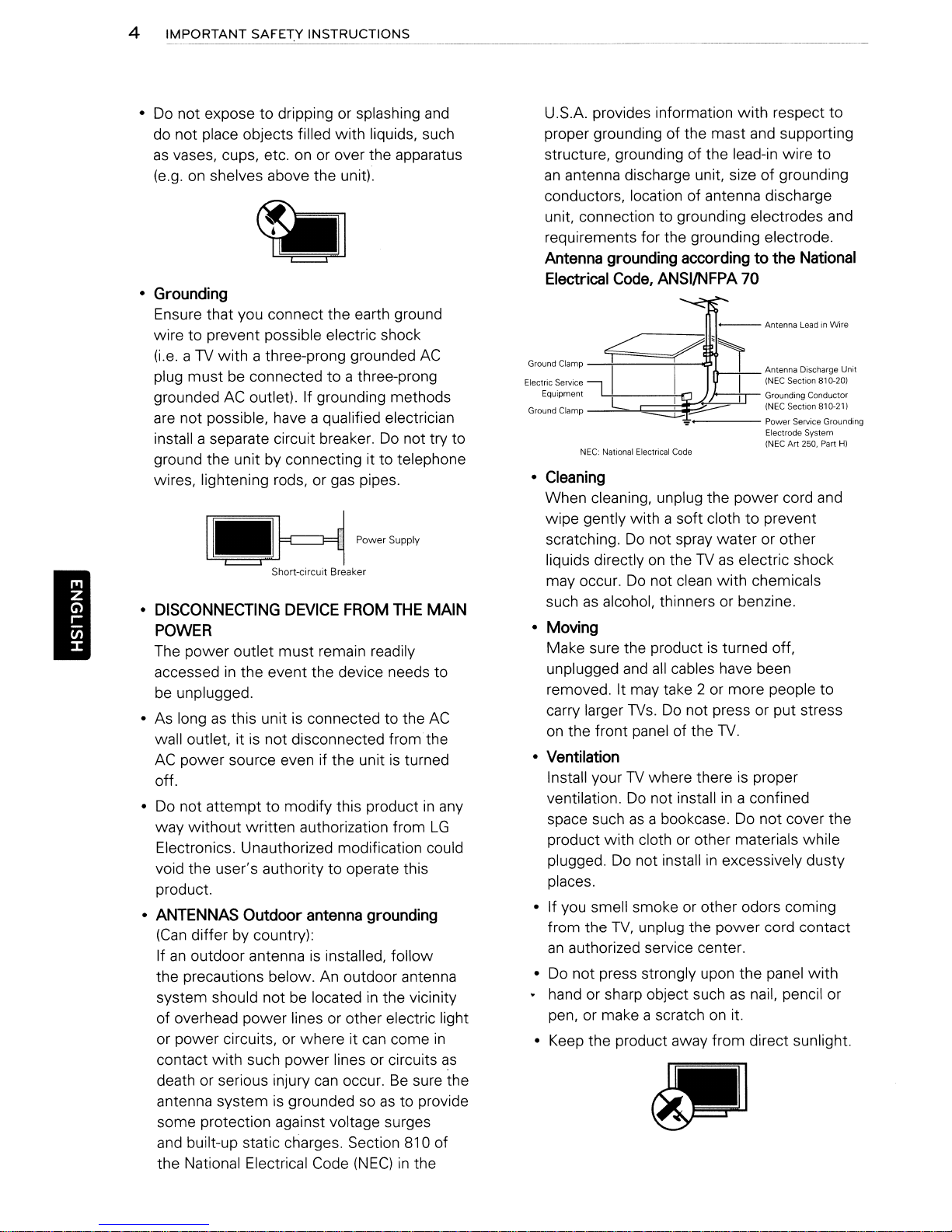
Do
not exposetodrippingorsplashing
•
do not place objects filled with liquids, such
as
vases, cups, etc.onor
(e.g.onshelves above the unit).
•
Grounding
Ensure that you connect the earth ground
wire to prevent possible electric shock
(i.e.aTV
plug must be connected to a three-prong
grounded
are
install a separate circuit breaker.
ground the unit
wires, lightening rods, or gas pipes.
with a three-prong grounded
AC
outlet). If grounding methods
not possible, have a qualified electrician
by
connecting it to telephone
I.H
Short-circuit Breaker
•
DISCONNECTING
DEVICE
over the apparatus
AC
Do
not try to
p~,S"~"
FROM
THE
POWER
The power outlet must remain readily
accessed
be
unplugged.
• As long
wall outlet, itisnot disconnected
AC
off.
•
Do
way without written authorization from
Electronics. Unauthorized modification could
void the user's authority to operate this
product.
•
ANTENNAS
(Can
If
an
the precautions below.
system should not be located
of overhead power lines or other electric light
or power circuits,
contact with such power lines or circuits
death or serious injury
antenna system is grounded so
some protection against voltage surges
and
the National Electrical Code
in
the event the device needs to
as
this unitisconnected to the
fromthe
power source even if the unitisturned
not attempt to modify this productinany
Outdoor
differ by country):
outdoor antennaisinstalled, follow
built-up static charges. Section 810 of
antenna
or
where it
grounding
An
outdoor antenna
in
the vicinity
can
come
can
occur.Besure the
as
to provide
(NEC)inthe
and
MAIN
AC
LG
in
as
U.S.A. provides information with respect to
and
proper grounding of the mast
structure, grounding of the lead-in wire
an
antenna discharge unit, size of grounding
conductors, location of antenna discharge
unit, connection to grounding electrodes and
requirements for the grounding electrode.
Antenna
Electrical
grounding
Code,
ANSI/NFPA
accordingtothe
supporting
National
70
---<
Ground Clamp
Electric Service
Equipment
Ground Clamp
NEe: National Electrical Code
•
Cleaning
When cleaning, unplug the power cord and
wipe gently with a soft cloth
Do
scratching.
liquids directly
may occur.
such
as
alcohol, thinners or benzine.
•
Moving
Make sure the productisturned off,
unplugged
removed. It may take 2
carry larger
on
the front panel of the
•
Ventilation
Install yourTVwhere thereisproper
ventilation.
space such
product with cloth
plugged.
places.
• If you smell smoke or other odors coming
from the
an
authorized service center.
•
Do
not press strongly upon the panel with
• hand or sharp object such
pen, or make a scratch
•
Keep
the product away from direct sunlight.
not spray water or other
on
theTVas
Do
not clean with chemicals
and
all
cables have been
or
TVs.Donot press or put stress
TV.
Do
not installina confined
as
a bookcase.
or
other materials while
Do
not installinexcessively dusty
TV,
unplug the power cord contact
on
Antenna Discharge Unit
(NEC Section 810-201
Grounding Conductor
(NEC Section 810-21)
Power
Service Grounding
Electrode System
Art
250. Part H)
(NEC
to
prevent
electric shock
more people to
Do
not cover the
as
nail, pencil or
it.
to
IMPORTANT
SAFETY
INSTRUCTIONS
5
•
Dot
Defect
The
PlasmaorLCD
technology product with resolution of
million to six million pixels.Ina very
cases, you could
while you're viewing the
are
deactivated pixels
performance
•
Generated
"Cracking" noise: A cracking noise that
occurs when watching or turning off the
is
generatedbyplastic thermal contraction
due to temperature
is
common for products where thermal
deformation
Electrical circuit humming/panel buzzing: A
low
level noiseisgenerated from a highspeed switching circuit, which supplies a
large amount of current to operate a product.
It varies depending
This generated sound does not affect the
performance
• Take
openings. When watching the
period, the ventilation openings may become
hot. This does not affect the performance of
the product or cause defects
•
Viewing3DImaging
- When viewing 3D imaging, watch the
fromaneffective viewing angle
the appropriate distance. If you exceed this
viewing angle or distance, you may not
able to view the3Dimaging. Furthermore,
the
while you
- If you watch the 3D imaging too closely or
for a long period of time, it may harm your
eyesight.
- Watching the
that incorporate
glasses for a long period of time
drowsiness, headaches or fatigue to you
and/or your eyes. If you have a headache,
or otherwise feel fatigued or drowsy, stop
watching the
- Pregnant woman, seniors, persons with
heart problems or persons
frequent drowsiness should refrain from
watching
- Some3Dimaging may cause you to duck
or dodge the image displayed
Sound
is
care
not to touch the ventilation
3D
imaging may not display if itisviewed
are
3D
panelisa high
see
fine dotsonthe screen
TV.
Those dots
and
do not affect the
and
reliability of the
and
humidity. This noise
required.
on
the product.
and
reliability of the product.
TV
in
(For
3D
TV)
lying down.
TV
or playing video games
3D
imaging with the 3D
TV
and
take a rest.
who
TV.
two
few
TV.
for a long
the product.
and
within
can
cause
experience
in
the video.
TV
TV
be
Therefore, itisbest if you do not watch 3D
TV
near fragile objects or near any objects
that
canbeknocked over easily.
- Please prevent children under the
5 from watching 3D
vision development.
- Warning for photosensitization seizure: Some
viewers may experience a seizure
when exposed
flashing lights or images
games. If you or anybody from your family
has
a history of epilepsy or seizure, please
consult with your doctor before watching 3D
TV.
Also certain symptoms
unspecified conditions without any previous
history. If
symptoms, immediately stop watching the
3D
lightheadedness, visual transition or altered
vision, visual or facial instability, such
or muscle twitching, unconscious action,
convulsion, loss of conscience, confusion
or disorientation, loss of directional sense,
cramps, or nausea. Parents should monitor
their children, including teenagers, for these
symptoms
the effects of watching 3D
Risk of photosensitization seizure
reduced with the following actions.
-
Take
-
For
in
each
taking vision correction measures.
- Watch the
same level
sitting too closely to the
-Donot watch the 3D imaging when tired or
sick,
long period of time.
-
Do
purpose than viewing 3D imaging
- Some viewers may feel disoriented after
watching 3D
3D
of your situation before moving.
you
imaging
those
and
not wear the 3D glasses for any other
TV,
and
as
frequent breaks from watching 3D
who
eye, they should watch theTVafter
TV
as
avoid watching the 3D imaging for a
TV.
take a moment to regain awareness
TV.
It may affect their
to
certain factors, including
inTVor video
can
experience
consult a doctor: dizziness or
they maybemore sensitive to
have vision thatisdifferent
so that your eyes
the 3D screen
Therefore, after you watch
any
TV.
TV.
age
of
or
epilepsy
occur
in
of the following
as
can
be
areonthe
and
refrain from
on
a 3D
eye
TV.
TV.
I
6
IMPORTANT
SAFEt:Y INSTRUCTIONS
I
••
If theTVfeels coldtothe touch, there may
be
a small "flicker"
is
normal, thereisnothing wrong with
Some minute
the screen, appearingastiny red, green, or
blue spots. However, they have
effect
on
the TV's performance. Avoid
touching the
finger(s) against it for long periods of time.
Doing so may produce some temporary
distortion effects
The fluorescent lamp used
a small amount of mercury.
this product
Disposal of this product must be carried out
in
accordance to the regulations of your local
authority.
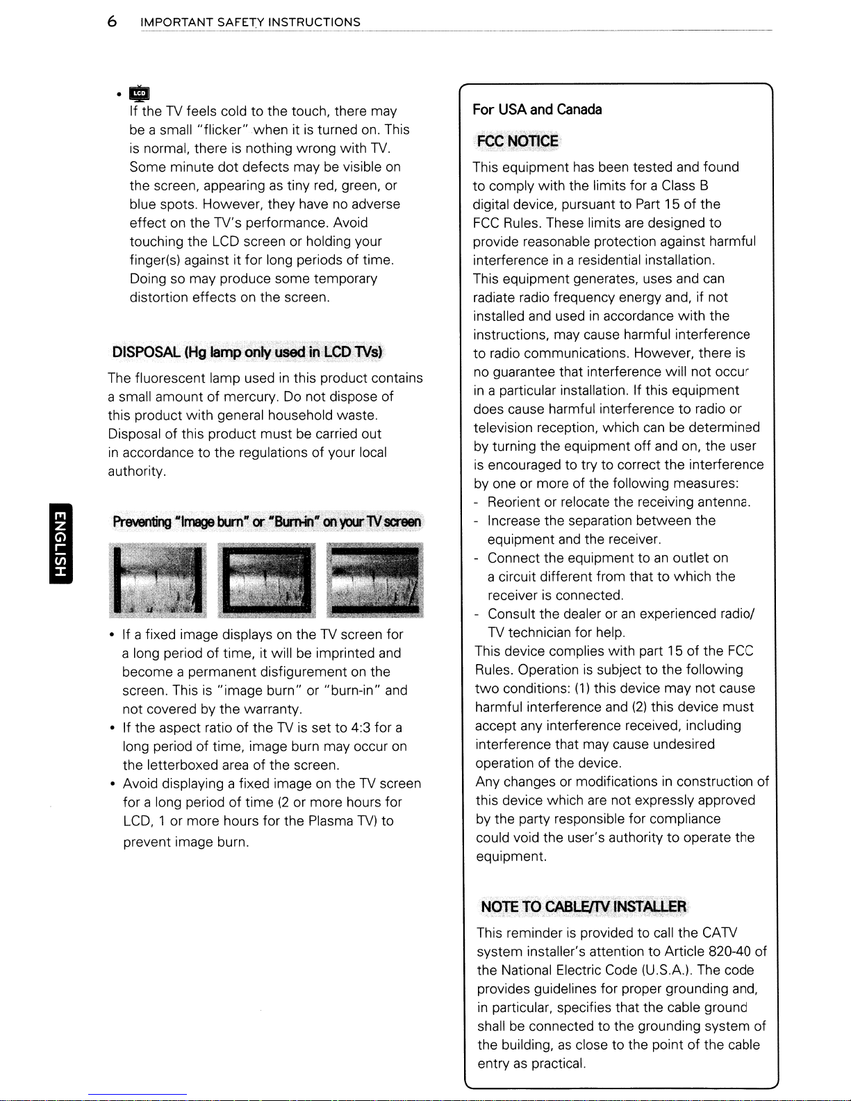
• If a fixed image displays
a long period of time, it will be imprinted
become a permanent disfigurementonthe
screen. This
not covered by the warranty.
• If the aspect ratio of the
long period of time, image burn may occur
the letterboxed
• Avoid displaying a fixed image
for a long period of time
LCD,
prevent image burn.
with
is
1 or more hours for the Plasma
whenitis
dot
defects may be visible
LCD
screen or holding your
on
the screen.
general household waste.
"image burn" or "burn-in"
area
of the screen.
turned
no
adverse
in
this product contains
Do
not dispose of
on
theTVscreen for
TV
is set to 4:3 for a
on
theTVscreen
(2
or more hours for
TV)
on.
TV.
and
This
on
and
on
to
For
USA
and
canada
This equipment
to comply with the limits for a Class B
digital device, pursuant to
FCC
Rules. These limits
provide reasonable protection against harmful
interference
This equipment generates, uses and
radiate radio frequency energy and, if not
installed and used
instructions, may cause harmful interference
to
radio communications. However, there
no guarantee that interference will not occur
in
a particular installation. If this equipment
does cause harmful interference
television reception, which
by turning the equipment off and on, the user
is
encouraged to try to correct the interference
by one or more of the following measures:
- Reorient or relocate the receiving antenna.
- Increase the separation between the
equipment
- Connect the equipment to
a circuit different from thattowhich the
receiver
- Consult the dealer or
TV
technician for help.
This device complies with part 15 of the
Rules. Operationissubject to the following
two
conditions:
harmful interference
accept any interference received, including
interference that may cause undesired
operation of the device.
Any changes
this device which
by the party responsible for compliance
could void the user's authority
equipment.
has
been tested and found
Part
15 of the
are
designed to
in
a residential installation.
in
accordance
and
the receiver.
is
connected.
an
(1)
this device may not cause
and
(2)
or
modificationsinconstruction of
are
not expressly approved
with
to
can
be determined
an
outlet
experienced radiol
this device
to
operate the
can
the
is
radio or
on
FCC
must
This reminder
system installer's attention to Article 820-40 of
the National Electric Code (U.S.A.). The code
provides guidelines for proper grounding and,
in
particular, specifies that the cable ground
shall be connected to the grounding system of
the building,
entry
as
is
as
practical.
provided to call the
close to the point of the cable
CATV
TABLE OF CONTENTS
IMPORTANT SAFETY INSTRUCTIONS
2
TABLE OF CONTENTS
7
7
Additional
8 ASSEMBLING AND PREPARING
8
Unpacking
11
Optional
12 Parts
20
Lifting
20
Settingupthe
20
25
25
-
Attaching
-
Mounting
-
Mounting
informationofthe
Extras
and
buttons
and
moving
TV
the
stand
onatable
on
a wall
the
manual
TV
TABLE OF
44
ENTERTAINMENT
44
-
Connecting
45
-
Browsing
47
TROUBLESHOOTING
49
SPECIFICATIONS
53
OPEN SOURCE SOFTWARE NOTICE
files
USB
storage
CONTENTS
devices
Additional information
manual
of
7
the
27
REMOTE CONTROL
30
WATCHING
30
Connectingtoan
30
30
30
31
32
33
33
34
34
35
37
37
38
39
40
40
40
41
41
42
42
42
43
-
Connectinganantennaorbasic
Connectingtothe
Turning
Watching
Using
3D
3D
-
-
Viewing
theTVon
TV
the
quick
IMAGING (FOR
Technology
When
using
30
Imaging
30
Imaging
CUSTOMIZING
The
Main
Menus
MAKING CONNECTIONS
Connection
Connectingtoa
player
-
HDMI
- DVItoHOMI
-
Component
-
Composite
Connectingtoa PC
- HOMI
- DVItoHDMI
- RGB
overview
Connection
Connection
Connection
TV
antennaorcable
AC/DC
for
the
menu
3D
30
Glasses
Viewing
Connection
Connection
Connection
Connection
Range
TV
SETTINGS
HD
receiver, DVO,orVCR
adapter
first
time
TV)
cable
View.ing'th~
The
owner's
supplied
Qwger';
manual
on a CD.
manual
in a PDF
Install
the
file
Adobe
format
Reader to view the owner's manualonyour
Insert the supplied
The
web
page appears automatically.
2 Click Owner's Manual
11IooCO""Iu~"""'''P_.",,,,_''''''''o-l''''~
-~'7IU-..I_.......,".I~
«r"
."',
CD.
..
I~_."""'~~
t'"~"
on
the
web
page.
__
........ "
''''_
......
.....
....,
3 View the owner's manual.
ONaTE
• If the
automatically, access
click
manual.
-------------..
web
page does not appear
LG
and
index.htm
My
computer
and
to view the owner's
ONOTE--------------------,
•
::=:
:Plasma
• inlage shown may differ from your
• Your TV's
differ slightly from that shown
TV
OSD
11II
:
LED
(On
Screen Display) may
LCD
TV,
TV.
in
this manual.
LCD
is
Acrobat
PC.
I
then
TV
ASSEMBLING AND PREPARING
Unpacking
I
Check your product box for the following items.Ifthere
dealer where you purchased your product. The illustrations
and
product
item.
are
D
Remote control and batteries
Polishing cloth'
on
(Depending
Gently wipe the spots
model)
on
(AM)
the cabinet with the polishing cloth.
Owner's manual
any missing accessories, contact the local
in
this manual may differ from the actual
CD
manual
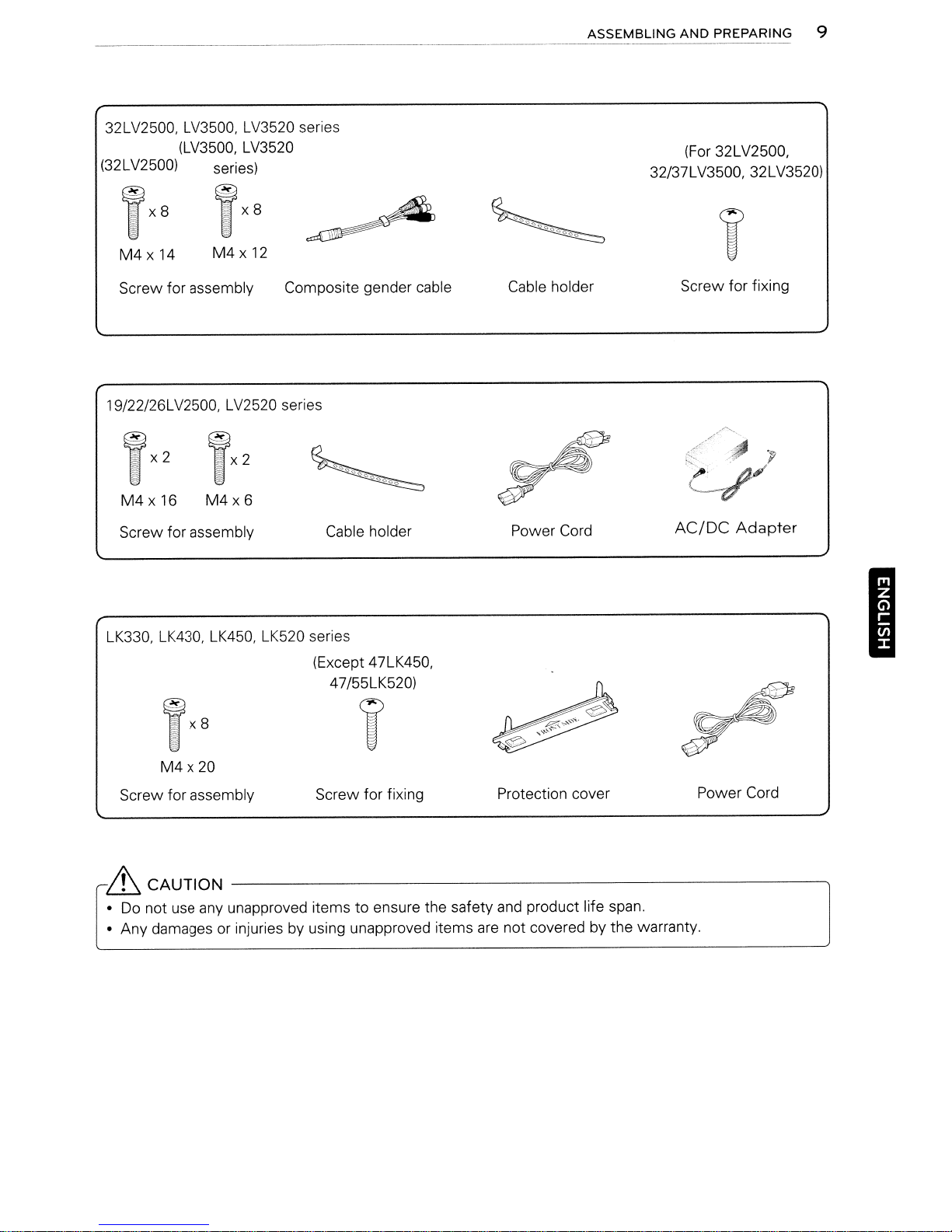
PW340, PW350, PW350U, PW350R,
(Other models)
M4
x 26
M5
x 14.5
Screw for assembly
Power Cord Protection cover Ferrite core
(For
M4
PZ200
60PZ200)
x 28
M5
series
x 24
Cable holder
(Depending
on
Power Cord holder
Protection cover tape
model)
32LV2500. LV3500. LV3520 series
(LV3500. LV3520
(32LV2500) series)
ASSEMBLING
32/37LV3500, 32LV3520)
AND
PREPARING 9
(For 32LV2500,
M4x
14
Screw for assembly Composite gender cable Cable holder Screw for fixing
19/22/26LV2500. LV2520 series
TX2
M4x16
Screw for assembly Cable holder Power Cord
LK330. LK430. LK450. LK520 series
M4x12
TX2
M4x6
009<:>0<:>0<:>0
~
(Except 47LK450,
47/55LK520)
~
AC/DC
Adapter
"P
I
TX8
T
M4x20
Screw for assembly Screw for fixing Protection cover Power Cord
~
CAUTION
•
Do
not use any unapproved items to ensure the safety and product life span.
• Any damages or injuries by using unapproved items
-----------------------------,
are
not covered by the warranty.
~

10
ASSEMBLING
AND
PREPARING
oNOTE
• The items supplied
• Product specifications or contents of this manual may
upgrade of product functions.
•
(I;;)
How
to use the ferrite core
1 Use the ferrite core to reduce the electromagnetic interference
Wind the
[toanExternal device)
PC
with
your product may vary dependingonthe model.
be
audio cableonthe ferrite core thrice. Place the ferrite core close to the
,_
~""Im",IjJn--.----------((~
~.(+1-5mm)
changed without prior notice due
in
thePCaudio cable.
TV.
ItotheTVI
to
(0)
I
[Figure
2 Use the ferrite core to reduce the electromagnetic interference
on
Wind the power cable
[to a wall plug)
3 Use the ferrite core
Wind the power cable
plug.
[to a wall plug)
- If there
- If there
- If there
• (..)
mm
is
one ferrite core, followasshowninFigure
are
two
are
three ferrite cores, followasshowninFigures 1
Foranoptimal connection, HDMI cables
(0.39 inches) thick
ferrite cores, followasshowninFigures 1 and
the ferrite core once.
~((==~
[Figure
to
reduce the electromagnetic interferenceinthe power cable.
on
the ferrite core once. Place the ferrite core close to theTVand
~((====~
[Figure
and18mm
(0.7 inches) width.
Place
and
11
the ferrite core close to the
2)
31
1.
USB
devices should have bezels less than
in
the power cable.
2.
and
3.
[totheTVI@
[Cross Section of
Ito the
TVI@
[Cross Section of
[Cross Section of
Ferrite Core)
TV.
Ferrite Corel
a wall
Ferrite Corel
10
*A<10
*8<18
mm
mm
(0.39
(0.7
inches)
inches)
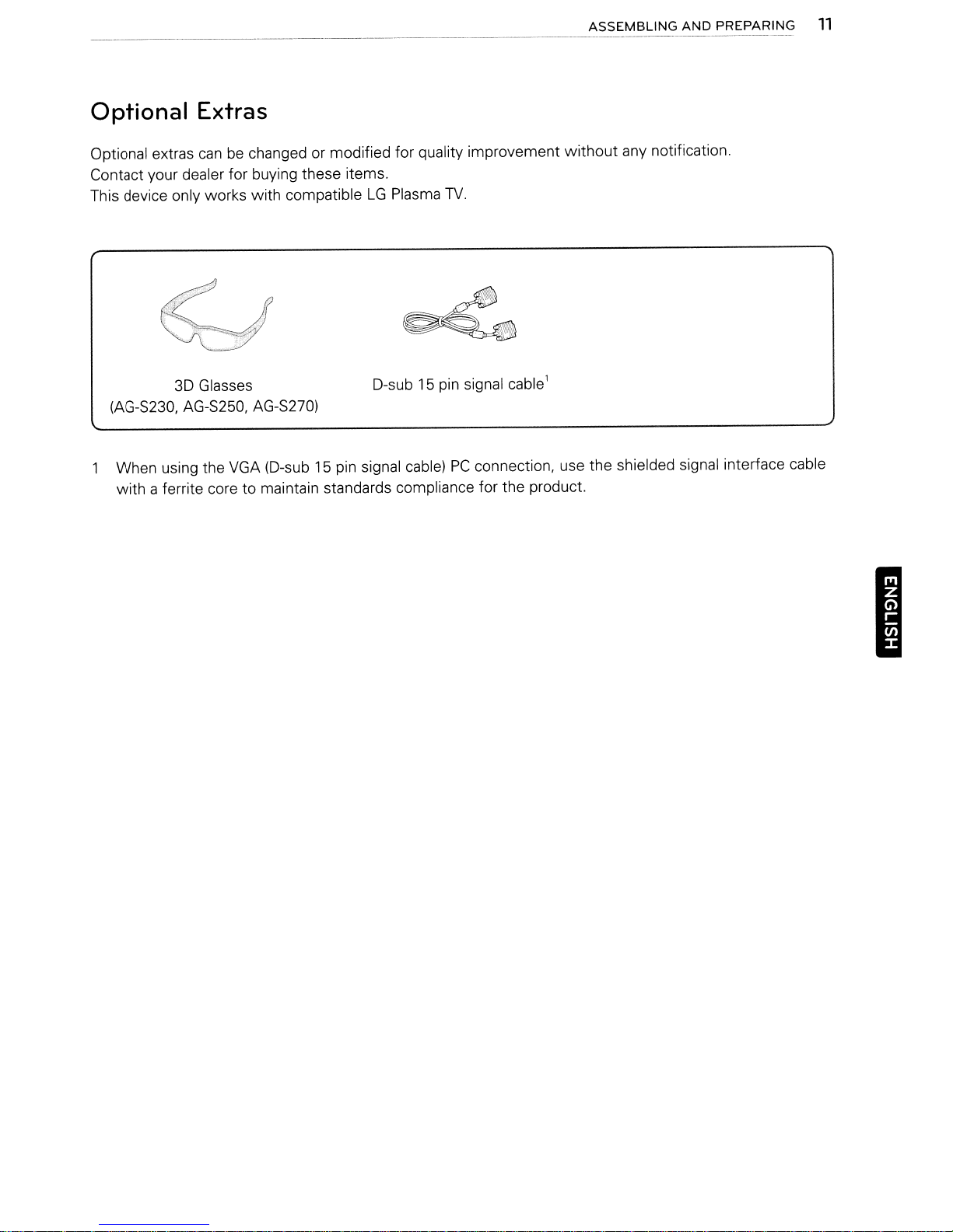
Optional Extras
ASSEMBLING
AND
PREPARING
11
Optional extras
Contact your dealer for buying these items.
This device only works
canbechanged or modified for quality improvement
with
/.'
compatibleLGPlasma
..
f·
TV.
without
any notification.
~
3D Glasses
(AG-S230. AG-S250,
When using the VGA (D-sub 15 pin signal cable)PCconnection, use the shielded signal interface cable
with
a ferrite core to maintain standards compliance for the product.
AG-S27O)
D-sub15pin signal cable1
I
12
ASSEMBLING
AND
PREPARING
Parts and
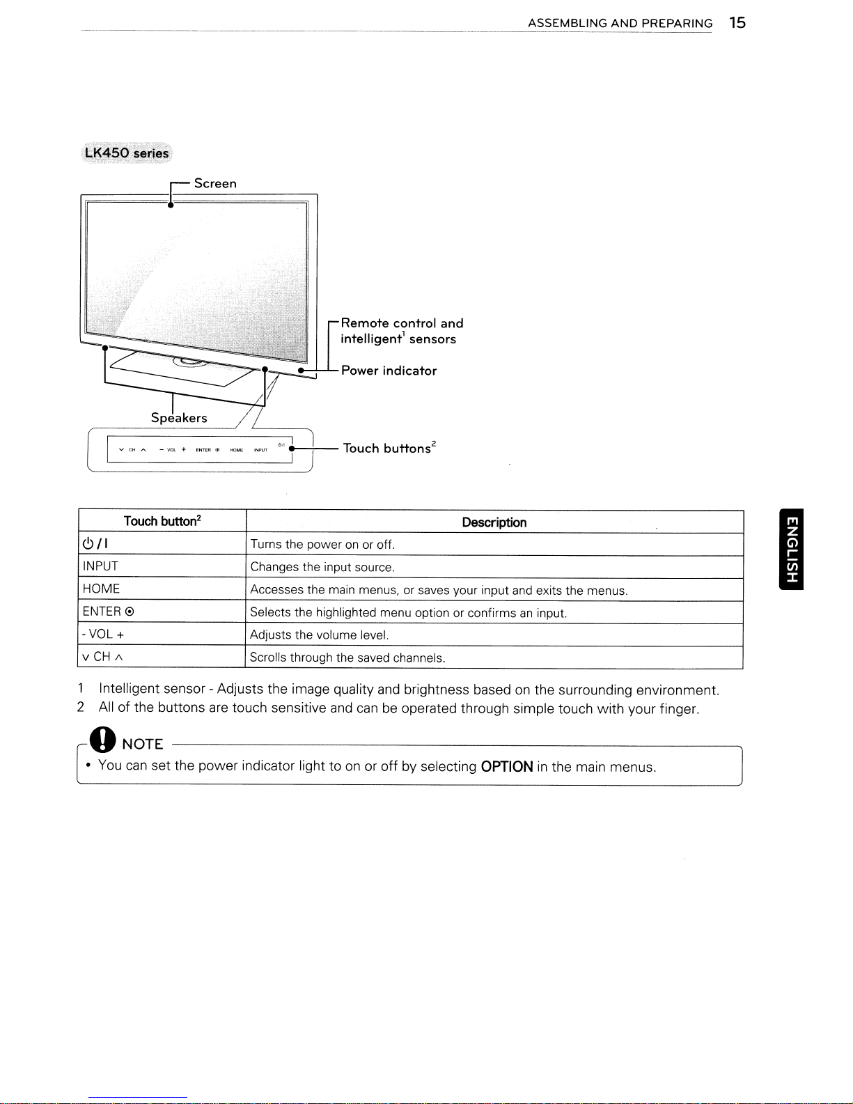
r;;;;;;;;;;;;;;;;;;;;;;;;;;;;;;;;;;;;;:;~
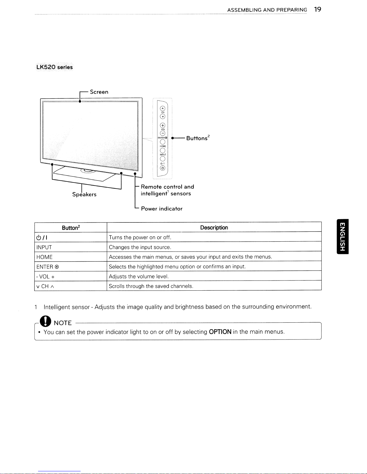
buttons
Screen
--+---
Remote
intelligent1sensors
Touch
control
buttons
and
2
I
Touch
button"!
6/1
INPUT
HOME
ENTER
-VOL
/\CHv
1 Intelligent sensor - Adjusts the image quality
2 All of the buttons
0
+
Turns the poweronor off.
Changes the input source.
Accesses the main menus, or saves your input
Selects the highlighted menu option or confirms
Adjusts the volume level.
Scrolls through the saved channels.
are
touch sensitive
and
canbeoperated through simple touch with your finger.
Description
and
exits the menus.
an
input.
and
brightness basedonthe surrounding environment.
ASSEMBLING
AND
PREPARING 13
32LV2500,
rF;;;;:;;;;;;;:;;;~
6/1
INPUT Changestheinputsoume.
HOME Accesses the main menus, or saves your input
ENTER
-VOL+
v
CH
/\
LV3500, LV3520 series
Screen
button
2
Turns the poweronor off.
Adjusts the volume level.
Scrolls through the saved channels.
Description
Touch
0 Selects the highlighted menu option or confirmsaninput.
and
exits the menus.
I
1 Intelligent sensor - Adjusts the image quality
2
All
of the buttons
o
NOTE
•
You
can
set the power indicator light toonor
are
touch sensitive
and
brightness basedonthe surrounding environment.
and
canbeoperated through simple touch with your finger.
off
by selecting
OPTION
in
the main menus.
14
ASSEMBLING
AND
PREPARING
I
;191:22/26LY2goo;~Lv~52d
.,
,~j
.._ ,;'
-x,....
.,,-
"
·1
•.•
_
'0..':;'. _c'
,..--
__
~
Screen
VCHA
--------------'
-VOl+ENTER@
Touch button
2
<9/1
INPUT Changes the input source.
HOME Accesses the main menus,
ENTER
-VOL
v
0 Selects the highlighted menu option or confirmsaninput.
+ Adjusts the volume level.
CH
1\
series
-,-
~;
Remote
intelligent1sensors
Power
'0.'
'"""'
."
.f
---;--Touch
Turns the poweronor off.
Scrolls through the saved channels.
indicator
buttons
control
and
2
or
saves your input
Description
and
exits the menus.
1 Intelligent sensor - Adjusts the image quality
are
2 All of the buttons
touch sensitive
oNOTE
•
You
can
set the power indicator light toonor
and
brightness basedonthe surrounding environment.
and
canbeoperated through simple touch with your finger.
off
by selecting OPTIONinthe main menus.
ASSEMBLING AND PREPARING 15
fiF;;;;;;;;;;;;;;;;;;;;;;;;;;;;;;;;:;~
VCHA.
Touch button
6/1
INPUT
HOME Accesses the main menus, or saves your input and exits the menus.
ENTER
-VOL+
v
0 Selects the highlighted menu option or confirmsaninput.
CH
/\
-va.
Screen
+
ENTER@
2
Remote
intelligent1sensors
Power
_-+--
Turns the poweronor off.
Changes the input source.
Adjusts the volume level.
Scrolls through the saved channels.
Touch
control
indicator
buttons
2
and
Description
I
1 Intelligent sensor - Adjusts the image quality
2 All of the buttons
are
touch sensitive
oNOTE
•
You
can
set the power indicator light toonor
and
brightness basedonthe surrounding environment.
and
canbeoperated through simple touch with your finger.
off
by selecting OPTIONinthe main menus.
16
ASSEMBLING
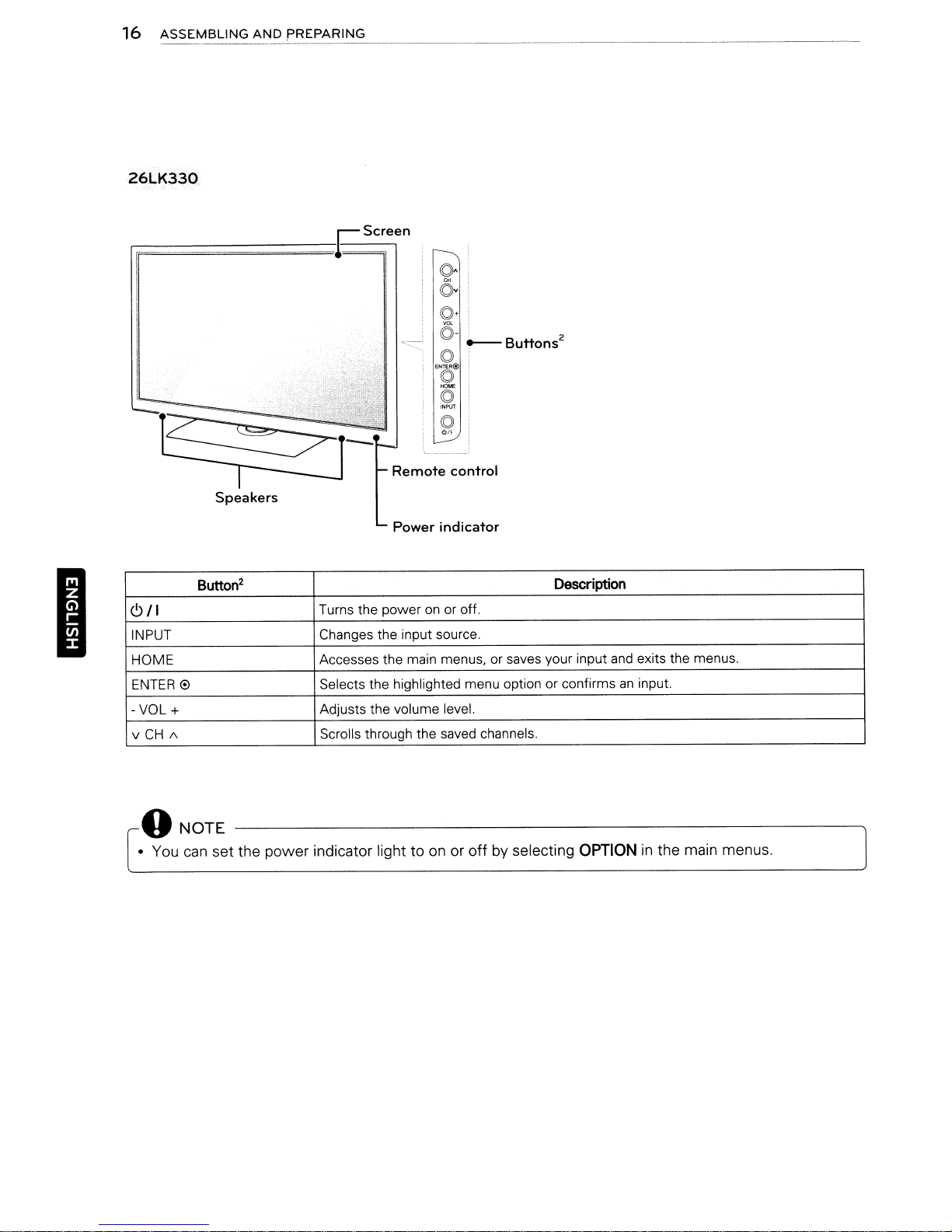
26LK330
AND
PREPARING
-------------------------------~
to·
c5v
to+
<5-
~c:--
to
ENTER@)
to
(5
INPUT
to
""
_
Buttons
2
Remote
Speakers
Power
2
Button
6/1
INPUT Changes the input source.
HOME
ENTER
-VOL+
v
0 Selects the highlighted menu option or confirmsaninput.
CH
/\
Turns the poweronor off.
Accesses the main menus, or saves your input
Adjusts the volume level.
Scrolls through the saved channels.
control
indicator
oNOTE
• You
can
set the power indicator light toonor offbyselecting
Description
and
OPTION
exits the menus.
in
the main menus.
Screen
(0.
6v
(0.
©-
! 2
~Buttons
(O!
ENTER@
I
(0,
HOME
I
(0'
INPUT
I
(O!
""
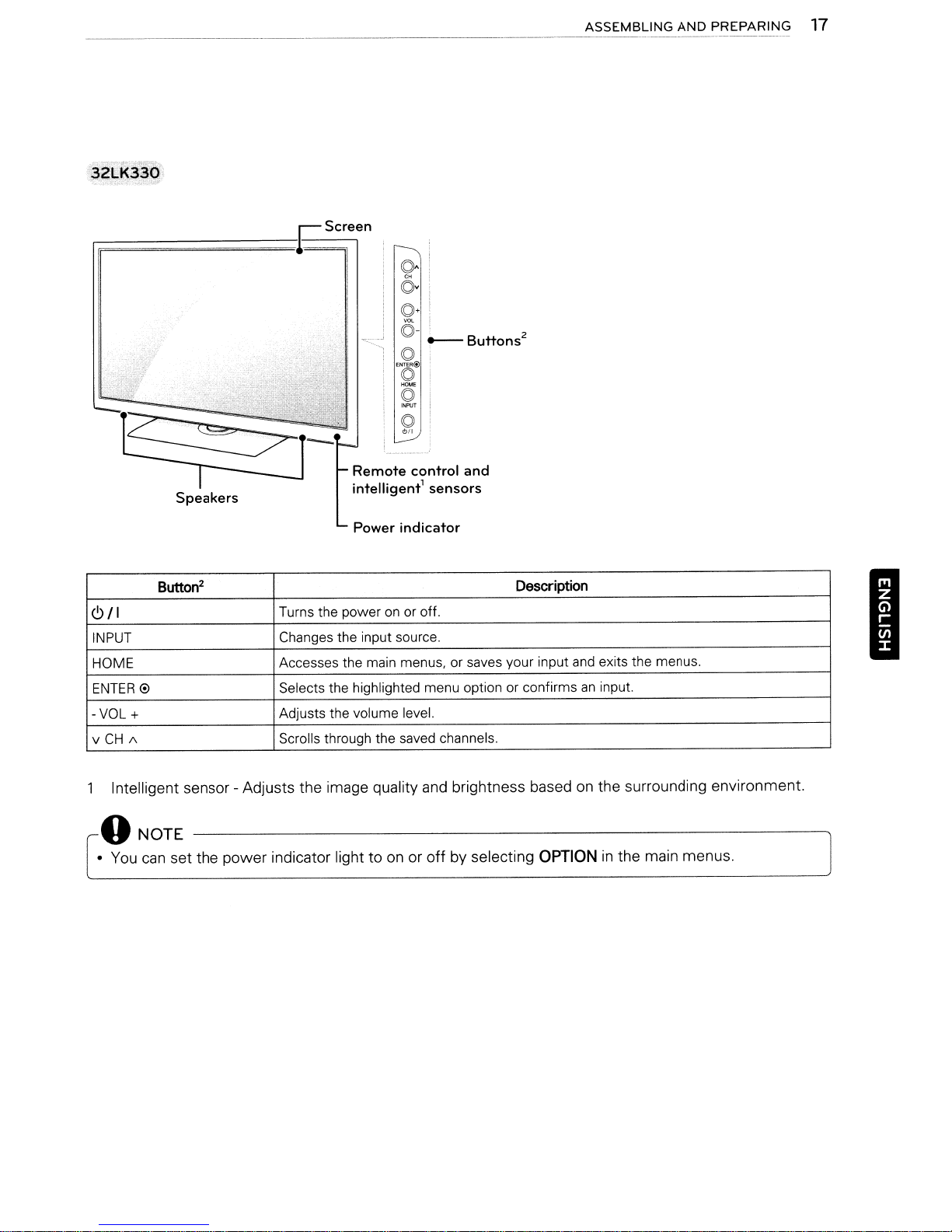
ASSEMBLING
AND
PREPARING
17
Remote
intelligent1sensors
Power
2
Button
<9/1
INPUT Changes the input source,
HOME Accesses the main menus, or saves your input
ENTER
0 Selects the highlighted menu optionorconfirmsaninput.
-VOL
+ Adjusts the volume level.
v
CH
/\
Intelligent sensor - Adjusts the image quality
o
NOTE
•
You
can
set the power indicator light toonor
Turns the poweronor off,
Scrolls through the saved channels,
control
indicator
and
off
and
Description
brightness basedonthe surrounding environment.
by selecting
OPTION
and
exits the menus,
in
the main menus.
I
18
ASSEMBLING
AND
PREPARING
I
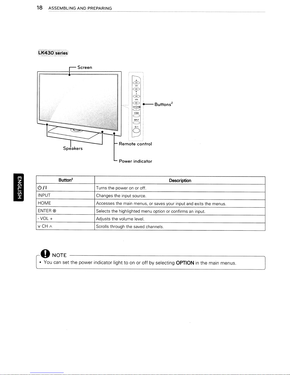
riF;;;;;;;;;;;;;;;;;;;;;;;;;;;;;;;;;;;;S
Button
6/1
INPUT Changes the input source.
HOME Accesses the main menus, or saves your input and exits the menus.
ENTER
-VOL+
v
CH
e
/\
2
Screen
A
c=::>
CH
c=::>
v
+
c==>
VOL
~
~Buttons2
1
0
HOME
c::::>
INPUT
""
o
Remote
Power
Turns the power on or off.
Selects the highlighted menu option or confirmsaninput.
Adjusts the volume level.
Scrolls through the saved channels.
control
indicator
Description
oNOTE
• You can
set
the
power
indicator light to on or
off
by selecting
OPTION
in
the main menus.
ASSEMBLING
AND
PREPARING
19
LK520
series
0)
G
o
i
G
I 2
ENTER@
~Buttons
o
HOME
o
INPUT
o
6/1
@i
Remote
intelligent'
Power
2
Button
6/1
INPUT Changes the input source.
HOME Accesses the main menus, or saves your input
ENTER
0
-VOL+
v
CH
/\
Turns the poweronor off.
Selects the highlighted menu option or confirms
Adjusts the volume level.
Scrolls through the saved channels.
control
sensors
indicator
and
Description
and
exits the menus.
an
input.
I
Intelligent sensor - Adjusts the image quality
o
NOTE
•
You
can
set the power indicator light toonor
and
brightness basedonthe surrounding environment.
off
by selecting OPTIONinthe main menus.
20
ASSEMBLING
AND
PREPARING
I
Lifting
When
to
prevent
damaged and for save transportation regardless
its type and size.
6
• Avoid touching the screen at
this may resultindamage to the screen.
• It
is
box or packing material that
came in.
• Before moving or lifting the
the
•
When
away
and moving
moving or lifting the
theTVfrom being scratched or
CAUTION
recommendedtomove theTVin
power
holding the
from
-------------.
cord and
youtoprevent damage.
all
TV,
the screen should face
TV,
read
TV,
cables.
the
the
all
times,
the
TV originally
disconnect
TV
following
as
the
~
• Hold the top and bottomofthe
firmly. Make sure not to hold the transparent
part, speaker, or speaker grill area.
TV frame
of
Setting
Put yourTVon a pedestal stand and mount the TV
on a table or wall.
Attaching
If you are not mounting theTVto
following instructions
PW340. PW350. PW3S0U
Lay the TV
surface.
&
• Lay a foam mat or soft protective cloth
2 Assemble
the STAND BASE of the
Model Screw
42/50PW340
42/50PW350
42/50PW350U
42/50PW350R
50PZ200
60PZ200
up
the
TV
the
stand
a wall, use the
to
attach the stand.
PW350R, PZ200 series
j
with
the screen side down on a flat
CAUTION
on the surface to protect the screen
damage.
against the screen.
Make
the
-------------..
sure no objects press
parts of the STAND BODY
TV.
for
assembly screws
M5x14.5
M5
x24
Number
3
3
from
with
of
•
When
transporting a large
be at least 2 people.
•
When
transporting theTVby hand, hold the
TVasshowninthe following illustration.
IGJ
•
When
transporting the
TVtojolts or excessive vibration.
•
When
transporting the
upright, never turn the TV on its side or tilt
towards
the left or right.
TV,donot
TV,
TV,
there should
expose
keep the TV
the
Stand
Base
---------------
ASSEMBLING
AND
PREPARING
21
3 Secure the
screws.
Model
42/50PW340
42/50PW350
42/50PW350U
42/50PW350R
50PZ200
60PZ200
TV
and the stand with the 4
Screwfor
assembly
M4
x 26 4
M4x28
& CAUTION
• Tighten the screws firmly to prevent
TV
the
tighten.
from tilting forward.
Number
screws
4
Do
not over
of
To
detach the stand,
1
Lay
theTVwith the screen side downona flat
surface.
2 Remove the 4 screws
from the
Model
42/50PW340
42/50PW350
42/50PW350U
42/50PW350R
50PZ200
60PZ200
TV.
Screw
assembly
M4
x 26 4
M4
x 28
and
pull the stand away
for
Number of
screws
4
3
Push
the supplied protection cover into the
TV
opening at the bottom of the
place.
Attach the protection cover tape.
- This will protect the opening from
accumulating dust and dirt.
- When installing the wall mounting bracket,
use the Protection cover.
Protection
until it locks
Protection
cover
cover
in
I
tape
22
ASSEMBLING
AND
PREPARING
32LV2500,
1 Lay
surface.
&
• Lay a foam
2
Assemble
the
Model Screw
32LV2500
LV3500,
theTVwith
CAUTION
the
on
damage.
against
STAND BASEofthe
surfacetoprotect the screen
the
the
/
LV352Q
the
screen side
matorsoft
Make
sure no objects press
screen.
partsofthe STAND BODY
assembly screws
M4x
14
series
protective cloth
TV.
for
4
down
Number of
on a flat
from
with
3 Secure the TV and
screws.
Model
32LV2500
LV3500,
series
&
CAUTION
• Tighten
theTVfrom
tighten.
LV3520
Screw
assembly
M4x14
M4x12
the
screws
tilting forward. Do
the
stand
for
firmlytoprevent
with
Number of
screws
4
4
the
not
4
over
I
Model
LV3500,
series
LV3520
Stand
Screw
for
assembly
M4x12
Base
Number of
screws
4
To detach the stand,
1 Lay
2 Remove the 4
theTVwith
surface.
screws
from
the
TV.
Model Screw
32LV2500
LV3500,
series
LV3520M4x
the
screen side
and pull
for
assembly
M4x14
12
down
the
stand away
Number of
screws
4
4
on a flat
ASSEMBLING
AND
PREPARING
23
19/22/26LV2500,
Lay
theTVwith
surface.
it
CAUTION
•
Lay
a foam matorsoft protective cloth
on
the surface to protect the screen from
damage. Make sure
against the screen.
LV2520 series
the screen side downona flat
no
objects press
2 Assemble the parts of the STAND BODY
the STAND
Screw
M4x6
for
assembly
BASE
of the
TV.
Numberofscrews
2
.......
~
i
Stand
Body
with
To
detach the stand.
1
Lay
theTVwith the screen side downona flat
surface.
2 Remove the 2 screws
for
16
TV.
assembly
from the
Screw
M4x
and
pull the stand away
Numberofscrews
2
3 Secure the
screws.
Screw
M4x
it
• Tighten the screws firmly to prevent
the
tighten.
TV
and
for
assembly
16
CAUTION
TV
from tilting forward.
the stand with the 2
Numberofscrews
2
Do
I
not over
24
ASSEMBLING
AND
PREPARING
-------
---
----
---
I
LK330,
1
LK430, LK450,
Lay
theTVwith the screen side downona flat
surface.
&
CAUTION
•
Lay
a foam mat or soft protective cloth
on
the surface to protect the screen from
damage. Make sure no objects press
against the screen.
LK520
series
2 Assemble the parts of the STAND BODY
the STAND
Screw for
M4
x20
BASE
assembly
Stand
of the
TV.
Numberofscrews
4
Base
with
To
detach the stand,
1
Lay
theTVwith the screen side downona flat
surface.
2 Remove the 4 screws and pull the stand away
from the
Screw
M4
3
Push
opening at the bottom of the
place.
This will protect the opening from accumulating
dust
When installing the wall mounting bracket, use
the Protection cover.
TV.
for
assembly
x
20
the supplied protection cover into the
and
dirt.
Numberofscrews
4
TV
until it locks
in
3 Secure the
screws.
Screw for
M4
x 20
&
• Tighten the screws firmly to prevent
the
tighten.
TV
and the stand with the 4
assembly
CAUTION
TV
from tilting forward.
Numberofscrews
4
Do
Protection cover
not over
ASSEMBLING
AND
PREPARING
25
Mounting
Lift and tilt theTVinto its upright positionona
table.
- Leave a 10 cm
from the wall for proper ventilation.
onatable
(4
inches) (minimum) space
CJ:
.J
lOcm
2 Connect the power cord to a wall outlet.
&
CAUTION
•Donot place theTVnear oronsources
as
of heat,
damage.
this may resultinfire or other
Mounting
Attachanoptional wall mount bracket at the rear
TV
of the
bracket
floor. When you attach the
materials, please contact qualified personnel.
We recommend that you use
mount when mounting the
Make sure to use screws and wall mounts that
meet the
the wall mount kits are described
table.
on
on
a wall
carefully
a solid wall perpendicular to the
VESA
and
install the wall mount
TV
to other building
anLGbrand wall
TV
to a wall.
standard. Standard dimensions for
in
the following
I
.---0
NOTE
• Swivel20degrees to the left or right and
TV
adjust the angle of the
view.
20°
~I
:····>::;·
~<.-c.
I
iii
......
..
<::··/~I
~.
'.... ---
····u··;)
to suit your
__
...
_.'
.....
20°
~
Model 42/50PW340
42/50PW350
42/50PW350U
42/50PW350R
50PZ200
VESA
Standard
Numberofscrews
Wall mount bracket
(optional) PSW400BG,
Model 19/22/26LV2500 32LV2500
VESA 100 x 100 200 x 100
Standard
Numberofscrews
Wall mount bracket LSW100B, LSW100B,
(optional)
screw
screw
400 x 400 600 x 400
M6 M8
4 4
PSW400B,
DSW400BG
..
'.0;
~I~
=rr:=
...
_;.~._
19/22/26LV2520 32LV3500
26LK330 32LK330
M4
4 4
LSW100BG LSW100BG
60PZ200
PSW600B
J
JJllt
•
:0'
32LK430
32LK450
M4
'"
~
~
26
ASSEMBLING
AND
PREPARING
Model
VESA
Standard
Numberofscrews 4
Wall
(optional)
mount
screw
bracket
37LV3500
42LK430
37/42/47LK450
42/47LK520
200 x 200 400 x 400
M6
LSW200B, LSW400B,
LSW200BG
~
;,
':-----'-'- ' - -
. .
. .
"'Co;.'
-
?
___
:.0-"".0'."~___
Z
.
~
."'-
'--,
~
42/47/55LV3500
42LV3520
55LK520
M6
4
LSW400BG,
DSW400BG
~:-.~~_.->
}
Ii:
tl'&:
£=2
~,.:
~._L~·
.~•.~.:
I
REMOTE CONTROL
The
descriptionsinthis manual
Please read this manual carefully
To
replace batteries, open the battery cover, replace batteries
matching the
battery cover.
(±)
and
8 ends to the label inside the compartment,
To
remove the batteries, perform the installation actionsinreverse.
are
basedonthe buttonsonthe remote control.
and
use theTVcorrectly.
(1.5
V
and
AM)
close the
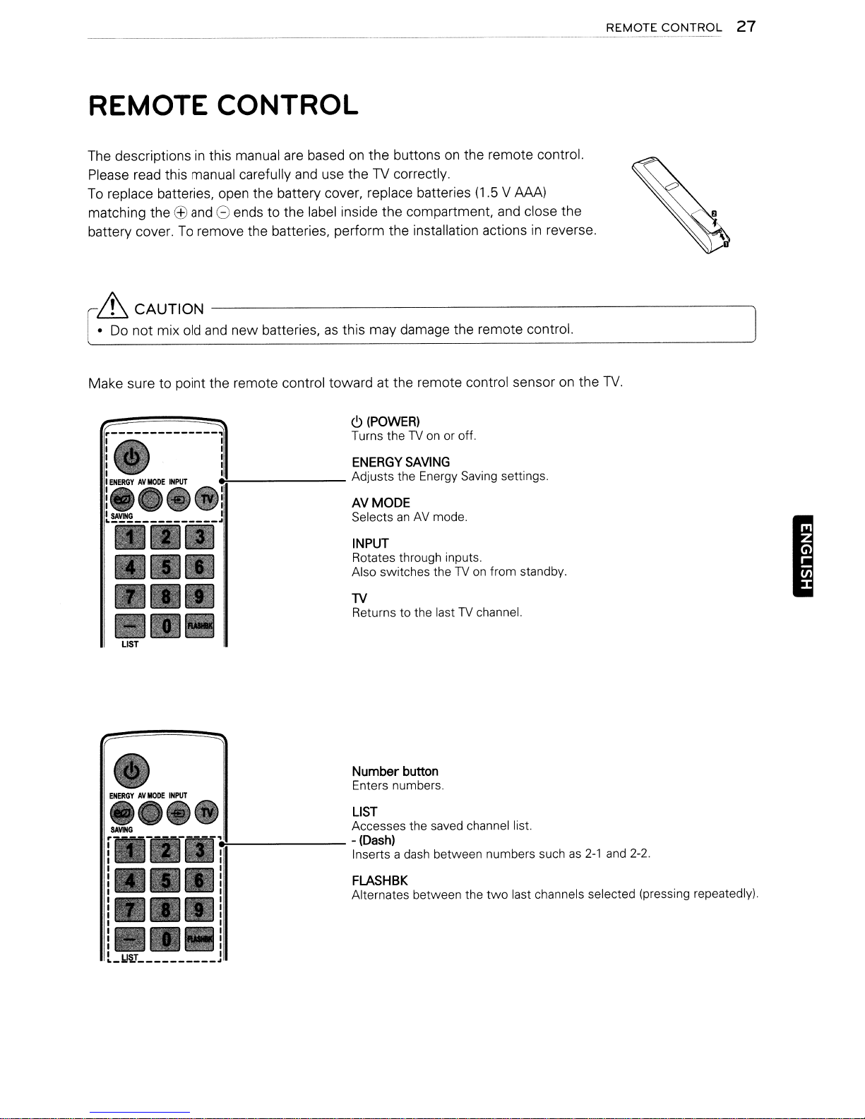
REMOTE
CONTROL
27
6 CAUTION
•
Do
not mix old
Make sure to point the remote control toward at the remote control sensor
LIST
-------------------------~
and
new batteries,asthis may damage the remote control.
<9
(POWER)
Turns theTVon
~
ENERGY
Adjusts the Energy Saving settings.
AVMODE
SelectsanAV
INPUT
Rotates through inputs.
Also switches the
TV
Returns to the lastTVchannel.
or off.
SAVING
mode.
TVonfrom standby.
on
the
TV.
I
e:-------
L_lJ§J
~
Number
Enters numbers.
LIST
Accesses the saved channel list.
-
(Dash)
Inserts a dash between numbers suchas2-1
FLASHBK
Alternates between the
button
two
last channels selected (pressing repeatedly).
and
2-2.
28
REMOTE
-~----
CONTROL
"--------
---
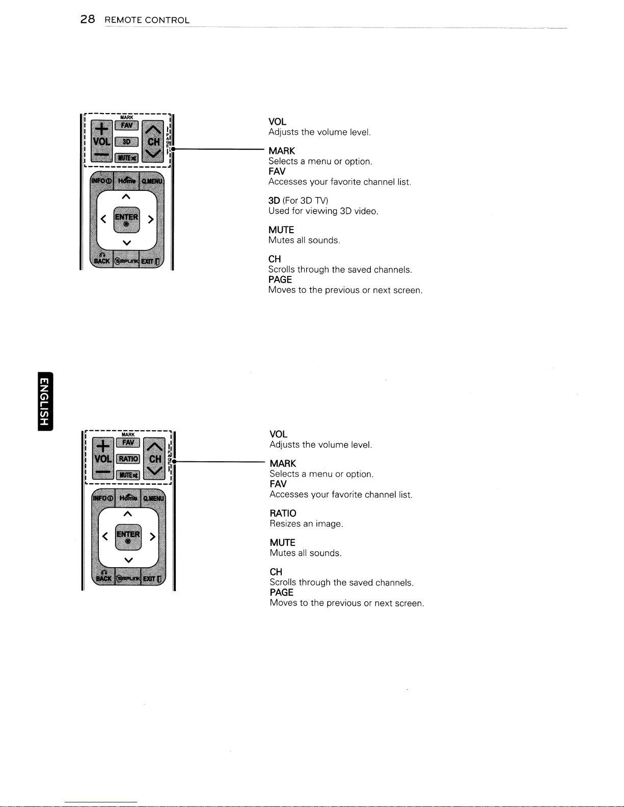
VOL
Adjusts the volume leveL
MARK
Selects a menu or option.
FAV
Accesses your favorite channel list.
--------"-"-----
I
'i-------
3D (For 3D
Used for viewing 3D video.
MUTE
Mutes
CH
Scrolls through the saved channels.
all
sounds.
TV)
PAGE
Moves to the previous or next screen.
VOL
Adjusts the volume leveL
MARK
Selects a menu or option.
FAV
Accesses your favorite channel list.
RATIO
Resizesanimage.
MUTE
Mutes
all
sounds.
CH
Scrolls through the saved channels.
PAGE
Moves to the previous or next screen.
REMOTE
CONTROL
29
r--------------ll
'----------;;;;11
: '
00_
11
L
.,.!---------
1
..
~I;.--------
..
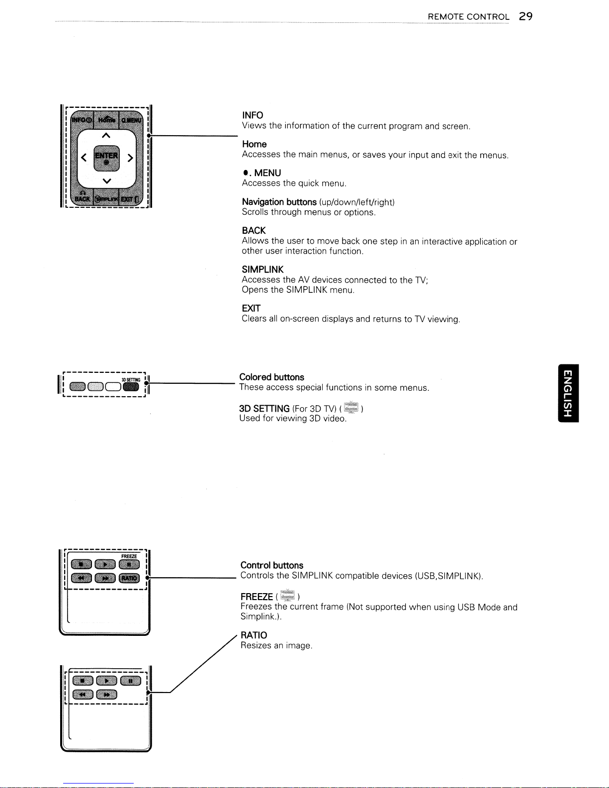
INFO
Views the information of the current program and screen.
Home
Accesses the main menus, or saves your input and exit the menus.
t.
MENU
Accesses the quick menu.
Navigation buttons (up/down/left/right)
Scrolls through menus or options.
BACK
Allows the user to move back one step
other user interaction function.
SIMPLINK
Accesses the
Opens the SIMPLINK menu.
EXIT
Clears
Colored buttons
These access special functionsinsome menus.
3D SETIING
Used for viewing
AV
devices connectedtothe
all
on-screen displays
(For3DTV)
3D
video.
and
~
(~)
inaninteractive application or
TV;
returns toTVviewing.
I
el--------
-------------~
I
Control buttons
Controls the SIMPLINK compatible devices (USB,SIMPLlNK).
FREEZE(=':)
Freezes the current frame (Not supported when using
Simplink.).
RATIO
Resizes
an
image.
USB
Mode
and
30
WATCHING
TV
WATCHING
Connecting
TV
to
an antenna or
cable
Connectanantenna, cable, or cable box to watch
TV
while referring to the following.
may differ from the actual items
optional.
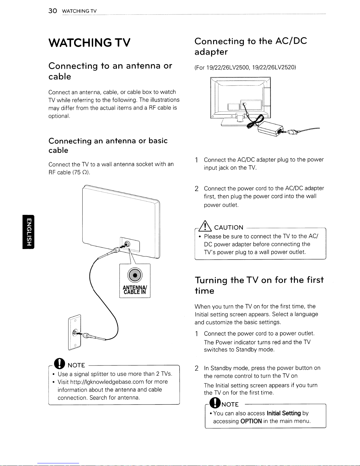
Connecting
an
antenna
cable
Connect theTVto a wall antenna socket with
RF
cable
(75
0).
The
illustrations
andaRF
or basic
cable
an
Connecting
to
the
AC/DC
adapter
(For 19/22/26LV2500, 19/22/26LV2520)
is
1 Connect the AC/DC adapter plug to the power
on
the
input jack
2 Connect the power cord to the AC/DC adapter
first, then plug the power cord into the wall
power outlet.
TV.
I
6 CAUTION
• Pleasebesure to connect theTVto the AC/
DC
power adapter before connecting the
TV's power plug to a wall power outlet.
Turning
time
When you turn theTVon
Initial setting screen appears. Select a language
and
customize the basic settings.
1 Connect the power cord to a power outlet.
The Power indicator turns red
switches to Standby mode.
f)NOTE----------~
•
Use
a signal splitter to use more than 2
• Visit http://lgknowledgebase.com for more
information about the antenna
connection. Search for antenna.
and
TVs.
cable
2
In
Standby mode, press the power button
the remote control to turn theTVon
The Initial setting screen appears if you turn
TVonfor the first time.
the
f)NOTE
•
You
accessing
the
can
also access
--------------..,
TV
on
for the first time, the
OPTION
in
for
the
and
the
Initial
Setting
the main menu.
first
TV
on
by
 Loading...