

Page 1

FOREWORD
Congratulations on your selection of this Lexus. In Lexus vehicles we have invested all our engineering and design resources; all
the know–how we have gained in over 60 years of making automobiles; the highest motivation of our most talented employees; and
our tradition of incessant striving toward ever greater quality.
This Owner’s Manual explains the features of your new Lexus. Please read it and follow the instructions carefully so that you can
enjoy many years of safe motoring.
When it comes to service, remember that your Lexus dealer knows your vehicle best and is interested in your complete satisfaction.
Your Lexus dealer will provide quality maintenance and any other assistance you may require.
If there is not a Lexus dealer near you, or you need emergency assistance for any reason, please call the following number:
U.S. OWNERS
When traveling in the U.S. mainland or Canada:
Lexus Roadside Assistance 1–800–25–LEXUS (Toll–Free)
HAWAII:
Lexus Customer Service Assistance 1–800–25–LEXUS (Toll–Free)
CANADIAN OWNERS
When traveling in Canada or the U.S. mainland:
Lexus Roadside Assistance/Customer Service1–800–26–LEXUS (Toll–Free)
Please leave this Owner’s Manual in this vehicle at the time of resale. The next owner will need this information also.
All information and specifications in this manual are current at the time of printing. However, because of the Lexus policy
of continual product improvement, we reserve the right to make changes at any time without notice.
Please note that this manual applies to all models and explains all equipment, including options. Therefore, you may find
some explanations for equipment not installed on your vehicle.
(1–800–255–3987)
(1–800–255–3987)
(1–800–265–3987)
2003 GS430/300 from May ’03 Prod. (OM30601U)
i
Page 2

INTRODUCTION
New vehicle warranty
Your new vehicle is covered by the following Lexus limited
warranties:
New vehicle warranty
Emission control systems warranty
Others
For further information, please refer to the “Owner’s Guide”,
“Owner’s Manual Supplement” or “Warranty Booklet”.
Your responsibility for maintenance
It is the owner’s responsibility to make sure the specified
maintenance is performed. Section 5 of this Owner’s Manual
gives details of these maintenance requirements. Included in
Section 6 is general maintenance. For scheduled
maintenance infor m a t i o n , p l ease refer to the “Owner’s Manual
Supplement / Scheduled Maintenance”.
Accessories, spare parts and modification of
your Lexus
A wide variety of non–genuine spare parts and accessories for
Lexus vehicles are currently available in the market. You
should know that Toyota does not warrant these products and
is not responsible for their performance, repair, or
replacement, or for any damage they may cause to, or adverse
effect they may have on, your Lexus vehicle.
This vehicle should not be modified with non–genuine Lexus
products. Modification with non–genuine Lexus products
could af fect its performance, safety or durability, and may even
violate governmental regulations. In addition, damage or
performance proble m s r e sulting from the modification may not
be covered under warranty.
Spark ignition system of your Lexus
The spark ignition system in your Lexus meets all
requirements of the Canadian Interference–Causing
Equipment Standard.
Installation of a mobile two–way radio system
As the installation of a mobile two–way radio system in your
vehicle could affect electronic systems such as the multiport
fuel injection system/sequential multiport fuel injection system,
cruise control system, anti–lock brake system, SRS airbag
system and seat belt pretensioner system, be sure to check
with your Lexus dealer for precautionary measures or special
instructions regarding installation.
Scrapping of your Lexus
The SRS airbag and seat belt pretensioner devices in your
Lexus contain explosive chemicals. If the vehicle is scrapped
with the airbags and seat belt pretensioners left as they are,
this may cause an accident such as fire. Be sure to have the
systems of the SRS airbag and seat belt pretensioner removed
and disposed of by a qualified service shop or by your Lexus
dealer before you scrap your vehicle.
ii
2003 GS430/300 from May ’03 Prod. (OM30601U)
Page 3

HOW TO USE THIS MANUAL
HOW TO USE THIS MANUAL
The contents of this manual are explained briefly on this
page to help you make the best use of the manual. Please
read this page and the rest of the Owner’s Manual
carefully to make sure you fully understand the operation
of your vehicle.
This will help you enjoy safe and comfortable driving.
TABLE OF CONTENTS
The table of contents and the pictorial index provide easy
reference to the appropriate pages.
BASIC OPERATION – QUICK REFERENCE
Operation of basic equipment is briefly explained in an easily
understandable way for quick reference.
SECTION 1 – INSTRUMENTS AND CONTROLS
The vehicle’s equipment is divided into the 7 groups listed
below. Use of the equipment is explained, including any points
you should pay particular attention to.
1. Keys and doors
2. Switches
3. Gauges, meters and service reminder indicators
4. Interior equipment
5. Exterior equipment
6. Comfort adjustment
7. Theft deterrent
SECTION 2 – AIR CONDITIONING AND AUDIO
The features of the vehicle’s air conditioning and audio are
explained in detail. Be sure to read this section so that you can
make full use of them.
SECTION 3 – STARTING AND DRIVING
Starting the engine, driving, stopping, operation of features
affecting vehicle handling, hints on vehicle safety and safe
driving techniques are all explained. Please read everything
in this section, and remember – drive safely!
SECTION 4 – IN CASE OF AN EMERGENCY
This section explains what to do in the event of an urgent
situation such as the engine not starting or getting a flat tire,
etc. If such a problem occurs, check the contents of this
Owner’s Manual and follow the instructions given.
SECTION 5 – MAINTENANCE
This section explains the importance of regular maintenance.
Regular and periodic inspection and maintenance of your
Lexus will help to keep your vehicle in its best condition.
SECTION 6 – SERVICE PROCEDURES AND
SPECIFICATIONS
Simple maintenance procedure and service data are provided
here for your reference should you wish to perform inspection
and maintenance yourself.
2003 GS430/300 from May ’03 Prod. (OM30601U)
iii
Page 4
HOW TO USE THIS MANUAL
INDEX
The page number is listed for each item in the Owner’s Manual
so that you can rapidly find the item and page you are
searching for.
GAS STATION INFORMATION
The information you need to know for appropriate servicing at
the gas station is provided here.
QUICK INDEX
This is designed so that you can quickly find the needed
information when an urgent situation arises.
Safety symbol
In this manual, you will also see a circle with a slash through
it. This means ”Do not”, ”Do not do this”, or ”Do not let this
happen”.
Safety and vehicle damage warnings
In this manual you will see CAUTION and NOTICE warnings.
These are used in the following ways:
CAUTION
This is a warning against anything which may cause
injury to people if the warning is ignored. You are
informed about what you must or must not do in order
to reduce the risk of injury to yourself and others.
NOTICE
This is a warning against anything which may cause
damage to the vehicle or its equipment if the warning is
ignored. Y ou are informed about what you must or must
not do in order to avoid or reduce the risk of damage to
your Lexus and its equipment.
Your Lexus Owner’s Manual provides you with a
considerable amount of information. To use this
information most effectively, please take the time to
familiarize yourself with the contents and use of the
manual.
iv
Page 5
PICTORIAL INDEX
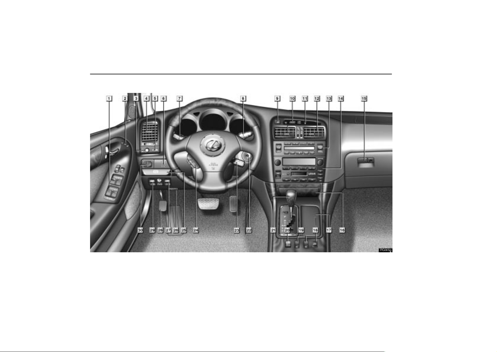
INSTRUMENT PANEL
PG005g
vi
2003 GS430/300 from May ’03 Prod. (OM30601U)
Page 6

PICTORIAL INDEX
1
Door lock switch and power window
switches 20, 32. . . . . . . . . . . . . . . . . . . . . . . . . . . . . . . . .
2
Driving position memory switch 130. . . . . . . . . . . . . .
3
Instrument panel light control 50. . . . . . . . . . . . . . . . .
4
Side vents 148. . . . . . . . . . . . . . . . . . . . . . . . . . . . . . . . . .
5
Security indicator light 134. . . . . . . . . . . . . . . . . . . . . .
6
Coin box (Vehicles sold in U.S.A.) 62. . . . . . . . . . . . .
Headlight cleaner switch
(Vehicles sold in Canada) 30. . . . . . . . . . . . . . . . . . . . .
7
Headlight, turn signal and fog light
switches 24, 26, 27. . . . . . . . . . . . . . . . . . . . . . . . . . . . . .
8
Wiper and washer switches 28. . . . . . . . . . . . . . . . . . .
9
Emergency flasher switch 35. . . . . . . . . . . . . . . . . . . .
10
Clock 54. . . . . . . . . . . . . . . . . . . . . . . . . . . . . . . . . . . . . . .
11
Front passenger’s seat belt reminder light 43. . . . .
12
Center vents 148. . . . . . . . . . . . . . . . . . . . . . . . . . . . . . . .
13
Automatic air conditioning controls 138. . . . . . . . . .
14
Car audio 152. . . . . . . . . . . . . . . . . . . . . . . . . . . . . . . . . .
Page
15
Glove box/CD automatic changer 57/164. . . . . . . . . .
16
Ashtray 55. . . . . . . . . . . . . . . . . . . . . . . . . . . . . . . . . . . . .
17
Cup holders 61. . . . . . . . . . . . . . . . . . . . . . . . . . . . . . . . .
18
Vehicle stability control system
OFF switch 194. . . . . . . . . . . . . . . . . . . . . . . . . . . . . . . . .
19
Seat heater switches 35. . . . . . . . . . . . . . . . . . . . . . . . .
20
Driving pattern selector switch 181. . . . . . . . . . . . . . .
21
Automatic transmission selector
lever 181. . . . . . . . . . . . . . . . . . . . . . . . . . . . . . . . . . . . . . .
22
Ignition switch 178. . . . . . . . . . . . . . . . . . . . . . . . . . . . . .
23
Cruise control switch 190. . . . . . . . . . . . . . . . . . . . . . .
24
Steering pad switch 169. . . . . . . . . . . . . . . . . . . . . . . . .
25
Parking brake release lever 179. . . . . . . . . . . . . . . . . .
26
Hood lock release lever 66. . . . . . . . . . . . . . . . . . . . . .
27
Trunk lid opener 67. . . . . . . . . . . . . . . . . . . . . . . . . . . . .
28
Parking brake 179. . . . . . . . . . . . . . . . . . . . . . . . . . . . . .
29
Fuel filler door opener 69. . . . . . . . . . . . . . . . . . . . . . . .
30
Power rear view mirror control switches 82. . . . . . .
Page
For detailed information, refer to the description given in each Section.
vii
Page 7
PICTORIAL INDEX
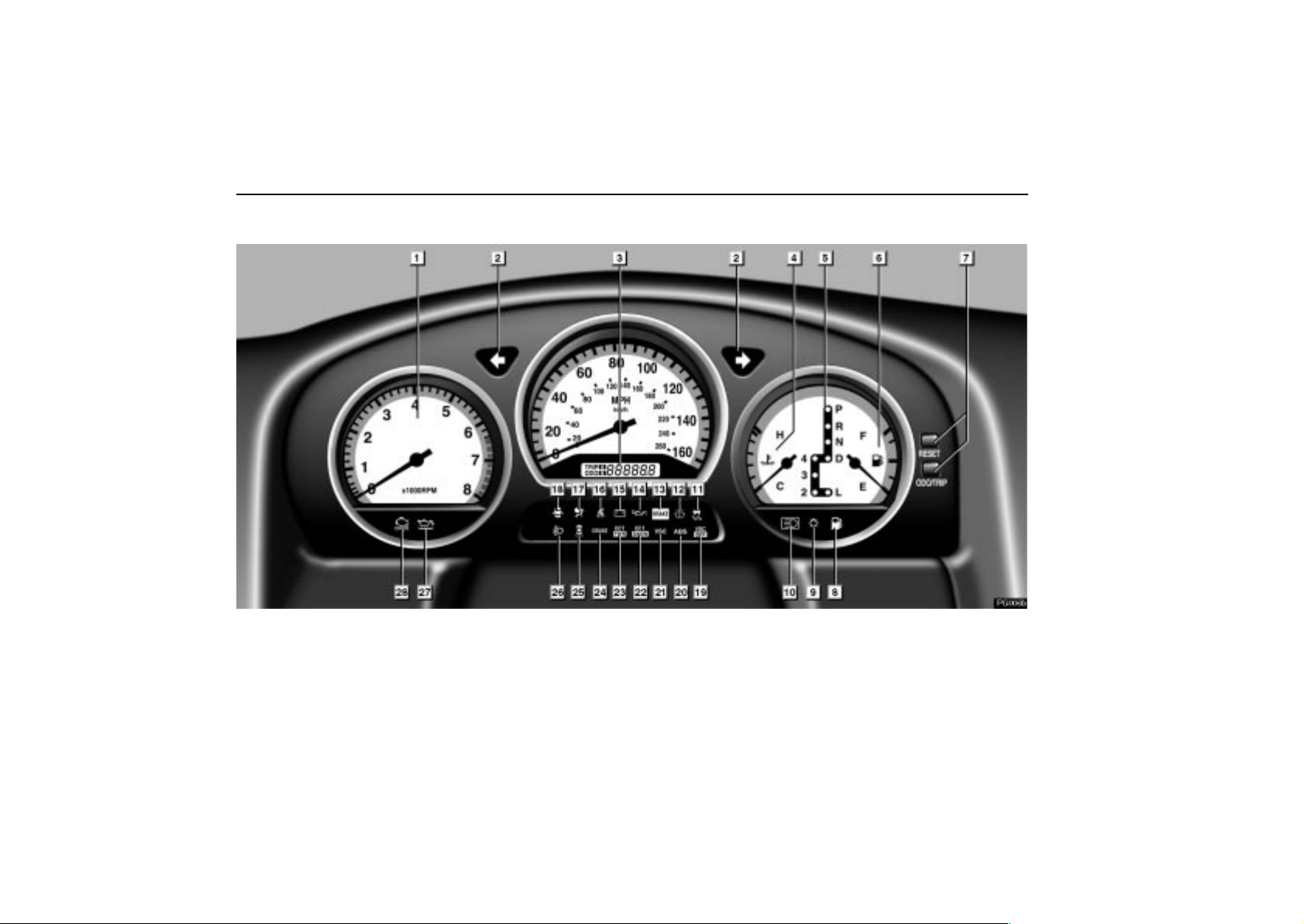
INSTRUMENT CLUSTER (GS430 sold in U. S. A.)
PG006b
viii
2003 GS430/300 from May ’03 Prod. (OM30601U)
Page 8

PICTORIAL INDEX
1
Tachometer 39. . . . . . . . . . . . . . . . . . . . . . . . . . . . . . . . .
2
Turn signal indicator light 26. . . . . . . . . . . . . . . . . . . .
3
Odometer and trip meter 40. . . . . . . . . . . . . . . . . . . . .
4
Engine coolant temperature gauge 38. . . . . . . . . . . .
5
Automatic transmission indicator lights 181. . . . . .
6
Fuel gauge 38. . . . . . . . . . . . . . . . . . . . . . . . . . . . . . . . . .
7
ODO/TRIP, RESET button 40. . . . . . . . . . . . . . . . . . . . .
8
Low fuel level warning light 48. . . . . . . . . . . . . . . . . . .
9
Headlight indicator light 24. . . . . . . . . . . . . . . . . . . . . .
10
Headlight high beam indicator light 26. . . . . . . . . . .
11
Slip indicator light 193, 194. . . . . . . . . . . . . . . . . . . . . .
12
Low washer fluid warning light 48. . . . . . . . . . . . . . . .
13
Brake system warning light 42. . . . . . . . . . . . . . . . . . .
14
Low engine oil pressure warning light 45. . . . . . . . .
15
Discharge warning light 44. . . . . . . . . . . . . . . . . . . . . .
Page
16
Driver’s seat belt reminder light 43. . . . . . . . . . . . . . .
17
SRS warning light 44. . . . . . . . . . . . . . . . . . . . . . . . . . . .
18
Open door warning light 48. . . . . . . . . . . . . . . . . . . . . .
19
Vehicle stability control system
OFF indicator light 194. . . . . . . . . . . . . . . . . . . . . . . . . .
20
Anti–lock brake system warning light 47. . . . . . . . . .
21
Vehicle stability control system
warning light 195. . . . . . . . . . . . . . . . . . . . . . . . . . . . . . .
22
Snow mode indicator light 189. . . . . . . . . . . . . . . . . . .
23
Power mode indicator light 189. . . . . . . . . . . . . . . . . .
24
Cruise control indicator light 190. . . . . . . . . . . . . . . .
25
Rear light failure warning light 48. . . . . . . . . . . . . . . .
26
Automatic headlight leveling system
warning light 48. . . . . . . . . . . . . . . . . . . . . . . . . . . . . . . .
27
Low engine oil level warning light 45. . . . . . . . . . . . .
28
Malfunction indicator lamp 46. . . . . . . . . . . . . . . . . . .
Page
For detailed information, refer to the description given in each Section.
ix
Page 9
PICTORIAL INDEX
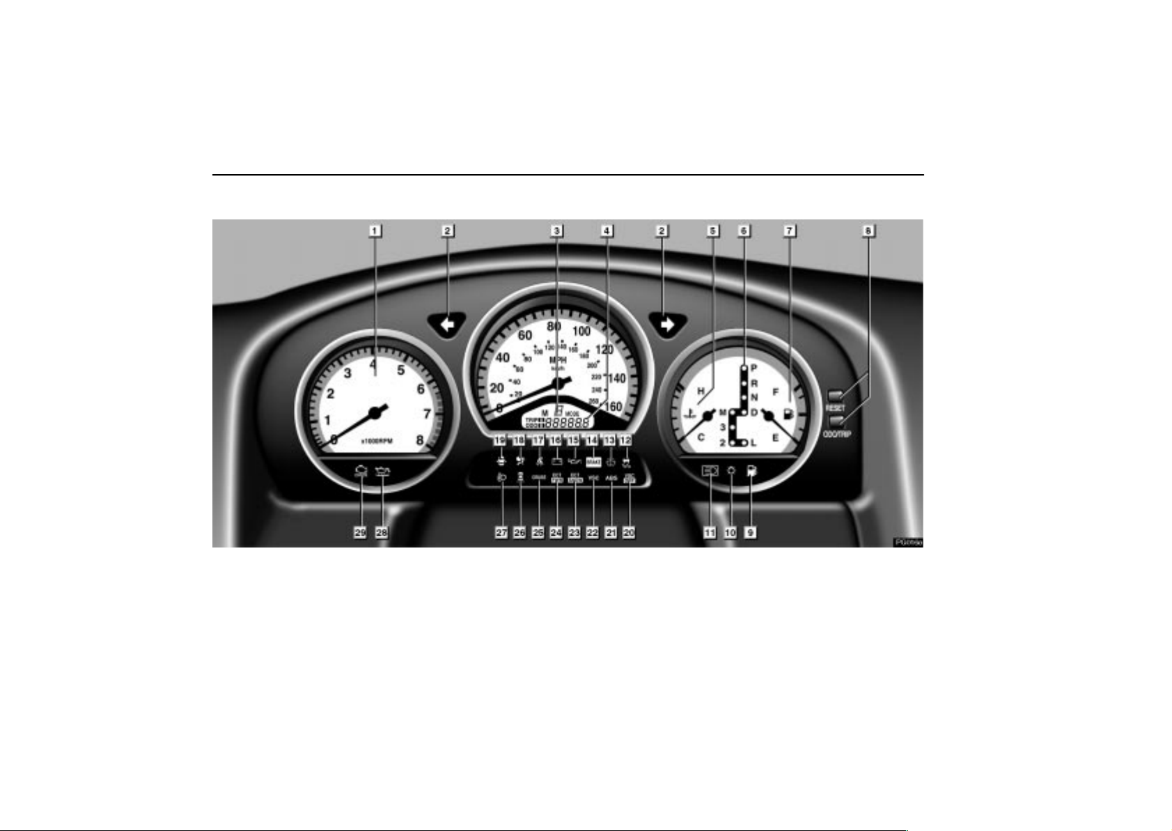
INSTRUMENT CLUSTER (GS300 sold in U. S. A.)
PG016e
x
2003 GS430/300 from May ’03 Prod. (OM30601U)
Page 10

PICTORIAL INDEX
1
Tachometer 39. . . . . . . . . . . . . . . . . . . . . . . . . . . . . . . . .
2
Turn signal indicator light 26. . . . . . . . . . . . . . . . . . . .
3
Shift position indicator for manual control 185. . . .
4
Odometer and trip meter 40. . . . . . . . . . . . . . . . . . . . .
5
Engine coolant temperature gauge 38. . . . . . . . . . . .
6
Automatic transmission indicator lights 181. . . . . .
7
Fuel gauge 38. . . . . . . . . . . . . . . . . . . . . . . . . . . . . . . . . .
8
ODO/TRIP, RESET button 40. . . . . . . . . . . . . . . . . . . . .
9
Low fuel level warning light 48. . . . . . . . . . . . . . . . . . .
10
Headlight indicator light 24. . . . . . . . . . . . . . . . . . . . . .
11
Headlight high beam indicator light 26. . . . . . . . . . .
12
Slip indicator light 193, 194. . . . . . . . . . . . . . . . . . . . . .
13
Low washer fluid warning light 48. . . . . . . . . . . . . . . .
14
Brake system warning light 42. . . . . . . . . . . . . . . . . . .
15
Low engine oil pressure warning light 45. . . . . . . . .
For detailed information, refer to the description given in each Section.
Page
16
Discharge warning light 44. . . . . . . . . . . . . . . . . . . . . .
17
Driver’s seat belt reminder light 43. . . . . . . . . . . . . . .
18
SRS warning light 44. . . . . . . . . . . . . . . . . . . . . . . . . . . .
19
Open door warning light 48. . . . . . . . . . . . . . . . . . . . . .
20
Vehicle stability control system
OFF indicator light 194. . . . . . . . . . . . . . . . . . . . . . . . . .
21
Anti–lock brake system warning light 47. . . . . . . . . .
22
Vehicle stability control system
warning light 195. . . . . . . . . . . . . . . . . . . . . . . . . . . . . . .
23
Snow mode indicator light 189. . . . . . . . . . . . . . . . . . .
24
Power mode indicator light 189. . . . . . . . . . . . . . . . . .
25
Cruise control indicator light 190. . . . . . . . . . . . . . . .
26
Rear light failure warning light 48. . . . . . . . . . . . . . . .
27
Automatic headlight leveling system
warning light 48. . . . . . . . . . . . . . . . . . . . . . . . . . . . . . . .
28
Low engine oil level warning light 45. . . . . . . . . . . . .
29
Malfunction indicator lamp 46. . . . . . . . . . . . . . . . . . .
Page
xi
Page 11
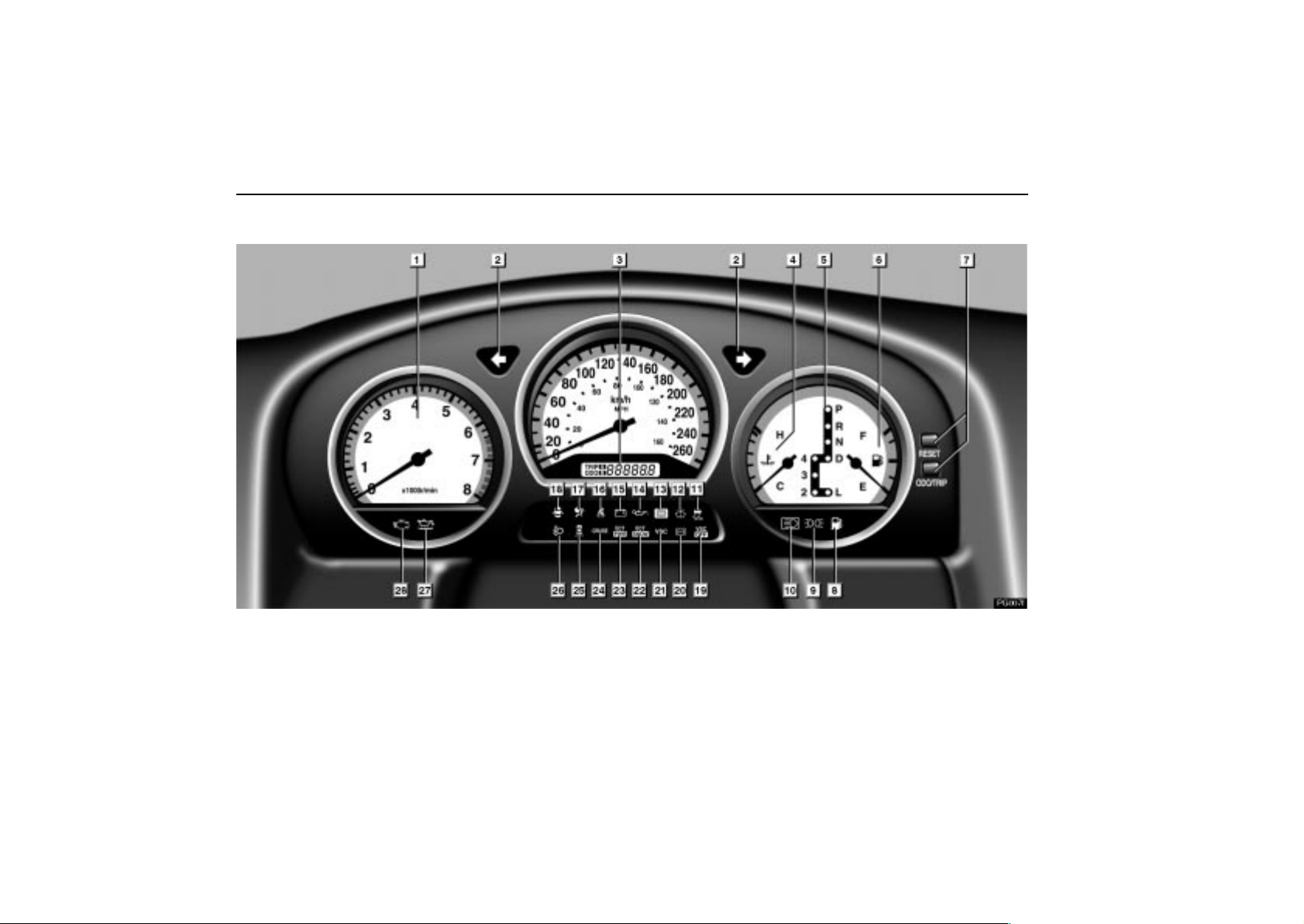
PICTORIAL INDEX
INSTRUMENT CLUSTER (GS430 sold in Canada)
PG007f
xii
2003 GS430/300 from May ’03 Prod. (OM30601U)
Page 12

PICTORIAL INDEX
1
Tachometer 39. . . . . . . . . . . . . . . . . . . . . . . . . . . . . . . . .
2
Turn signal indicator light 26. . . . . . . . . . . . . . . . . . . .
3
Odometer and trip meter 40. . . . . . . . . . . . . . . . . . . . .
4
Engine coolant temperature gauge 38. . . . . . . . . . . .
5
Automatic transmission indicator lights 181. . . . . .
6
Fuel gauge 38. . . . . . . . . . . . . . . . . . . . . . . . . . . . . . . . . .
7
ODO/TRIP, RESET button 40. . . . . . . . . . . . . . . . . . . . .
8
Low fuel level warning light 48. . . . . . . . . . . . . . . . . . .
9
Tail light indicator light 24. . . . . . . . . . . . . . . . . . . . . . .
10
Headlight high beam indicator light 26. . . . . . . . . . .
11
Slip indicator light 193, 194. . . . . . . . . . . . . . . . . . . . . .
12
Low washer fluid warning light 48. . . . . . . . . . . . . . . .
13
Brake system warning light 42. . . . . . . . . . . . . . . . . . .
14
Low engine oil pressure warning light 45. . . . . . . . .
15
Discharge warning light 44. . . . . . . . . . . . . . . . . . . . . .
Page
16
Driver’s seat belt reminder light 43. . . . . . . . . . . . . . .
17
SRS warning light 44. . . . . . . . . . . . . . . . . . . . . . . . . . . .
18
Open door warning light 48. . . . . . . . . . . . . . . . . . . . . .
19
Vehicle stability control system OFF
indicator light 194. . . . . . . . . . . . . . . . . . . . . . . . . . . . . .
20
Anti–lock brake system warning light 47. . . . . . . . . .
21
Vehicle stability control system
warning light 195. . . . . . . . . . . . . . . . . . . . . . . . . . . . . . .
22
Snow mode indicator light 189. . . . . . . . . . . . . . . . . . .
23
Power mode indicator light 189. . . . . . . . . . . . . . . . . .
24
Cruise control indicator light 190. . . . . . . . . . . . . . . .
25
Rear light failure warning light 48. . . . . . . . . . . . . . . .
26
Automatic headlight leveling system
warning light 48. . . . . . . . . . . . . . . . . . . . . . . . . . . . . . . .
27
Low engine oil level warning light 45. . . . . . . . . . . . .
28
Malfunction indicator lamp 46. . . . . . . . . . . . . . . . . . .
Page
For detailed information, refer to the description given in each Section.
xiii
Page 13
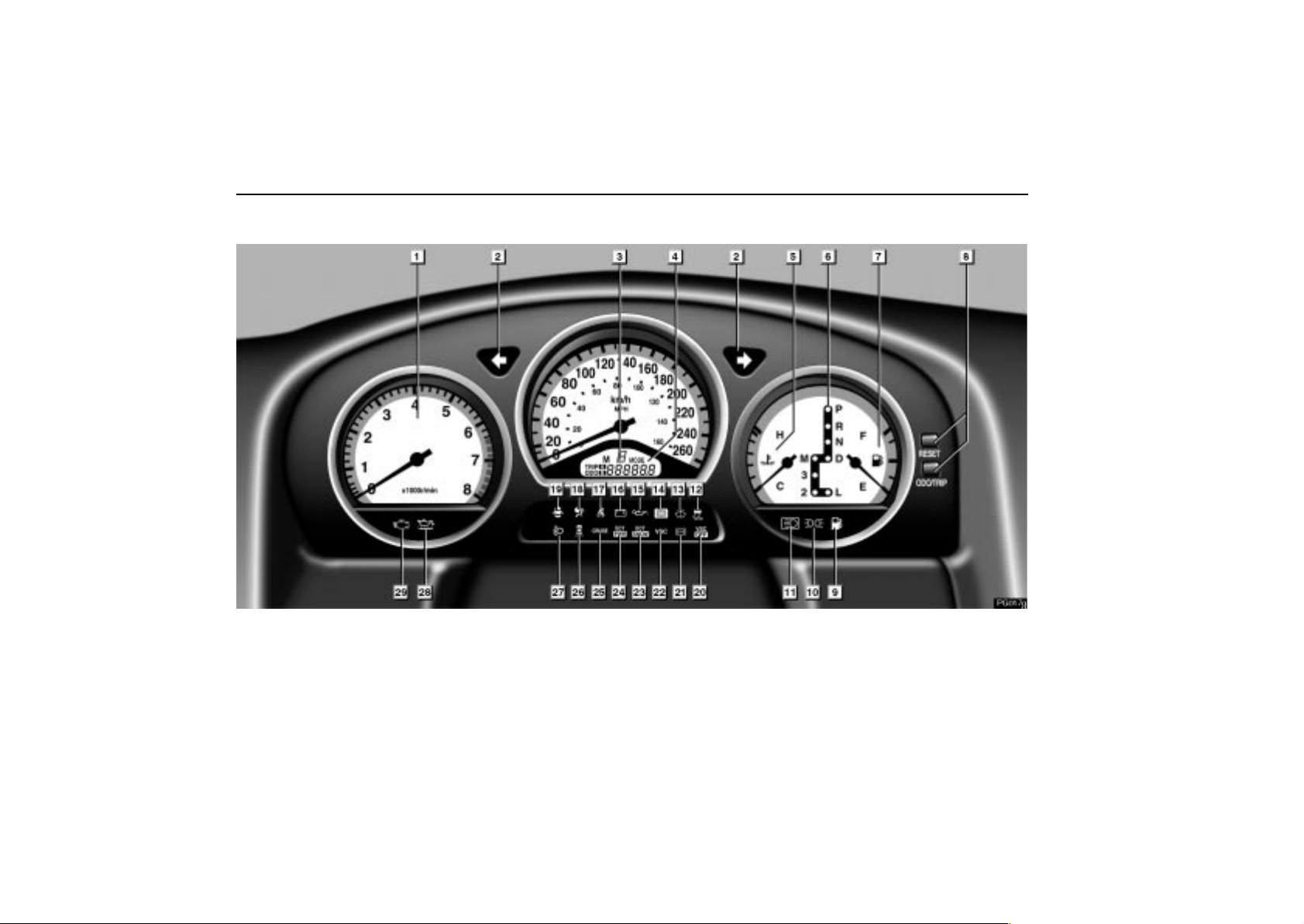
PICTORIAL INDEX
INSTRUMENT CLUSTER (GS300 sold in Canada)
PG017g
xiv
2003 GS430/300 from May ’03 Prod. (OM30601U)
Page 14

PICTORIAL INDEX
1
Tachometer 39. . . . . . . . . . . . . . . . . . . . . . . . . . . . . . . . .
2
Turn signal indicator light 26. . . . . . . . . . . . . . . . . . . .
3
Shift position indicator for manual control 185. . . .
4
Odometer and trip meter 40. . . . . . . . . . . . . . . . . . . . .
5
Engine coolant temperature gauge 38. . . . . . . . . . . .
6
Automatic transmission indicator lights 181. . . . . .
7
Fuel gauge 38. . . . . . . . . . . . . . . . . . . . . . . . . . . . . . . . . .
8
ODO/TRIP, RESET button 40. . . . . . . . . . . . . . . . . . . . .
9
Low fuel level warning light 48. . . . . . . . . . . . . . . . . . .
10
Tail light indicator light 24. . . . . . . . . . . . . . . . . . . . . . .
11
Headlight high beam indicator light 26. . . . . . . . . . .
12
Slip indicator light 193, 194. . . . . . . . . . . . . . . . . . . . . .
13
Low washer fluid warning light 48. . . . . . . . . . . . . . . .
14
Brake system warning light 42. . . . . . . . . . . . . . . . . . .
15
Low engine oil pressure warning light 45. . . . . . . . .
For detailed information, refer to the description given in each Section.
Page
16
Discharge warning light 44. . . . . . . . . . . . . . . . . . . . . .
17
Driver’s seat belt reminder light 43. . . . . . . . . . . . . . .
18
SRS warning light 44. . . . . . . . . . . . . . . . . . . . . . . . . . . .
19
Open door warning light 48. . . . . . . . . . . . . . . . . . . . . .
20
Vehicle stability control system OFF
indicator light 194. . . . . . . . . . . . . . . . . . . . . . . . . . . . . .
21
Anti–lock brake system warning light 47. . . . . . . . . .
22
Vehicle stability control system
warning light 195. . . . . . . . . . . . . . . . . . . . . . . . . . . . . . .
23
Snow mode indicator light 189. . . . . . . . . . . . . . . . . . .
24
Power mode indicator light 189. . . . . . . . . . . . . . . . . .
25
Cruise control indicator light 190. . . . . . . . . . . . . . . .
26
Rear light failure warning light 48. . . . . . . . . . . . . . . .
27
Automatic headlight leveling system
warning light 48. . . . . . . . . . . . . . . . . . . . . . . . . . . . . . . .
28
Low engine oil level warning light 45. . . . . . . . . . . . .
29
Malfunction indicator lamp 46. . . . . . . . . . . . . . . . . . .
Page
xv
Page 15
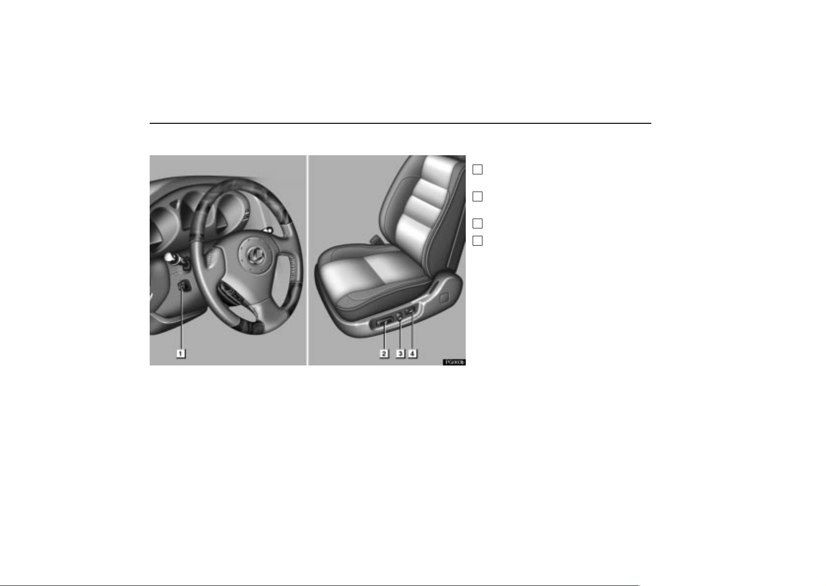
PICTORIAL INDEX
SEAT AND STEERING WHEEL
PG003b
1
Tilt and telescopic steering
adjustment switch 80. . . . . . . . . . . . . .
2
Seat position, seat cushion angle
and height control switch 77, 78. . . .
3
Seatback angle control switch 77. . .
4
Lumbar support control switch 78. .
For detailed information, refer to the
description given in each Section.
Page
xvi
2003 GS430/300 from May ’03 Prod. (OM30601U)
Page 16
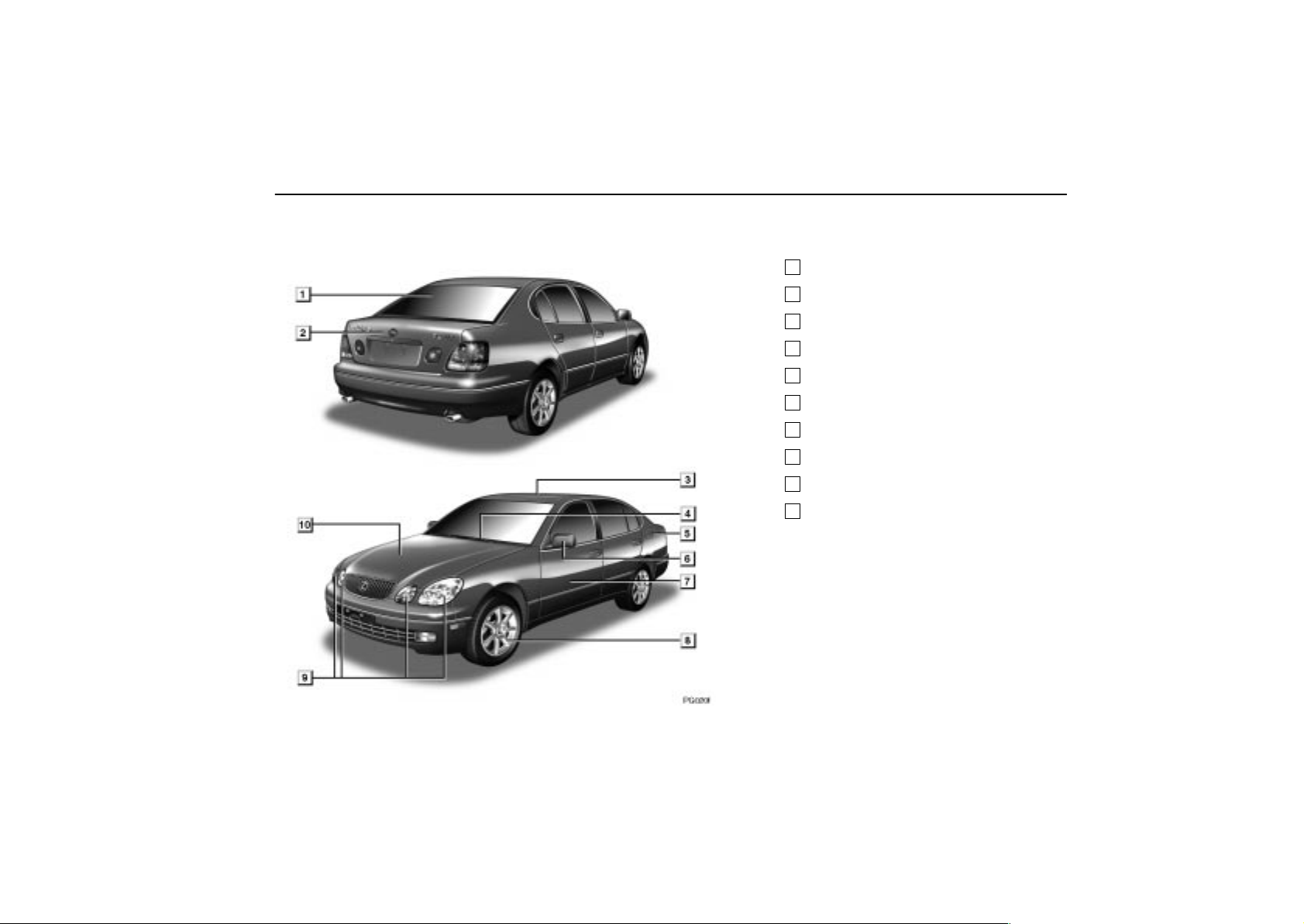
EXTERIOR VIEW
PG020f
PICTORIAL INDEX
1
Rear window defogger 31. . . . . . . . . .
2
Trunk lid 67. . . . . . . . . . . . . . . . . . . . . . .
3
Moon roof 70. . . . . . . . . . . . . . . . . . . . .
4
Wiper and washer 28, 303. . . . . . . . . .
5
Fuel filler door 69. . . . . . . . . . . . . . . . .
6
Outside rear view mirror 82. . . . . . . .
7
Door 19. . . . . . . . . . . . . . . . . . . . . . . . . .
8
Tire and wheel 282. . . . . . . . . . . . . . . .
9
Headlights 24, 309. . . . . . . . . . . . . . . . .
10
Hood 66. . . . . . . . . . . . . . . . . . . . . . . . . .
For detailed information, refer to the
description given in each Section.
Page
xvii
Page 17

PICTORIAL INDEX
xviii
2003 GS430/300 from May ’03 Prod. (OM30601U)
Page 18

BASIC OPERATION
QUICK REFERENCE
Driver’s seat 2. . . . . . . . . . . . . . . . . . . . . . . . . . . . . . . . . . . . . . . . . . . . . .
Steering wheel 2. . . . . . . . . . . . . . . . . . . . . . . . . . . . . . . . . . . . . . . . . . . .
Automatic transmission (GS430) 3. . . . . . . . . . . . . . . . . . . . . . . . . . . . .
Automatic transmission (GS300) 4. . . . . . . . . . . . . . . . . . . . . . . . . . . . .
Headlight and turn signal switches 5. . . . . . . . . . . . . . . . . . . . . . . . . . .
Wiper switch 6. . . . . . . . . . . . . . . . . . . . . . . . . . . . . . . . . . . . . . . . . . . . . .
1
Page 19
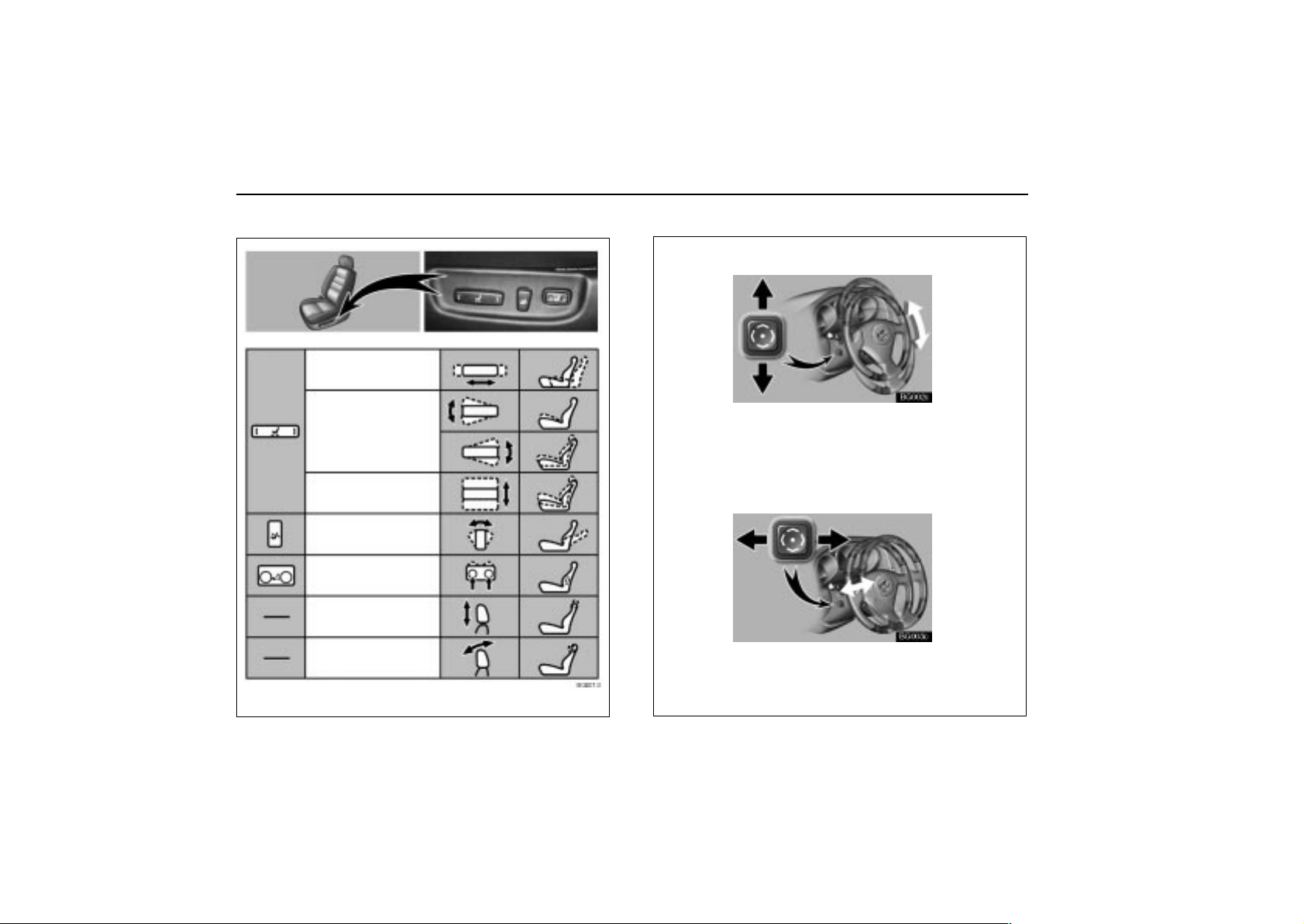
QUICK REFERENCE
1. DRIVER’S SEAT
Seat adjustment
Seat
position
Seat
cushion
angle
BG001–3
Seat cushion
height
Seatback
angle
Lumbar
support
Head restraint
height
Head restraint
angle
2. STEERING WHEEL
TILT STEERING WHEEL
BG002c
To tilt the steering wheel up or down to the desired angle,
push the control switch in the required direction and
release the button when the steering wheel reaches the
desired angle.
TELESCOPIC STEERING WHEEL
BG003c
To move the steering wheel to the desired position, push
the control switch away from you or pull it toward you until
the steering wheel reaches the desired position.
2
Page 20
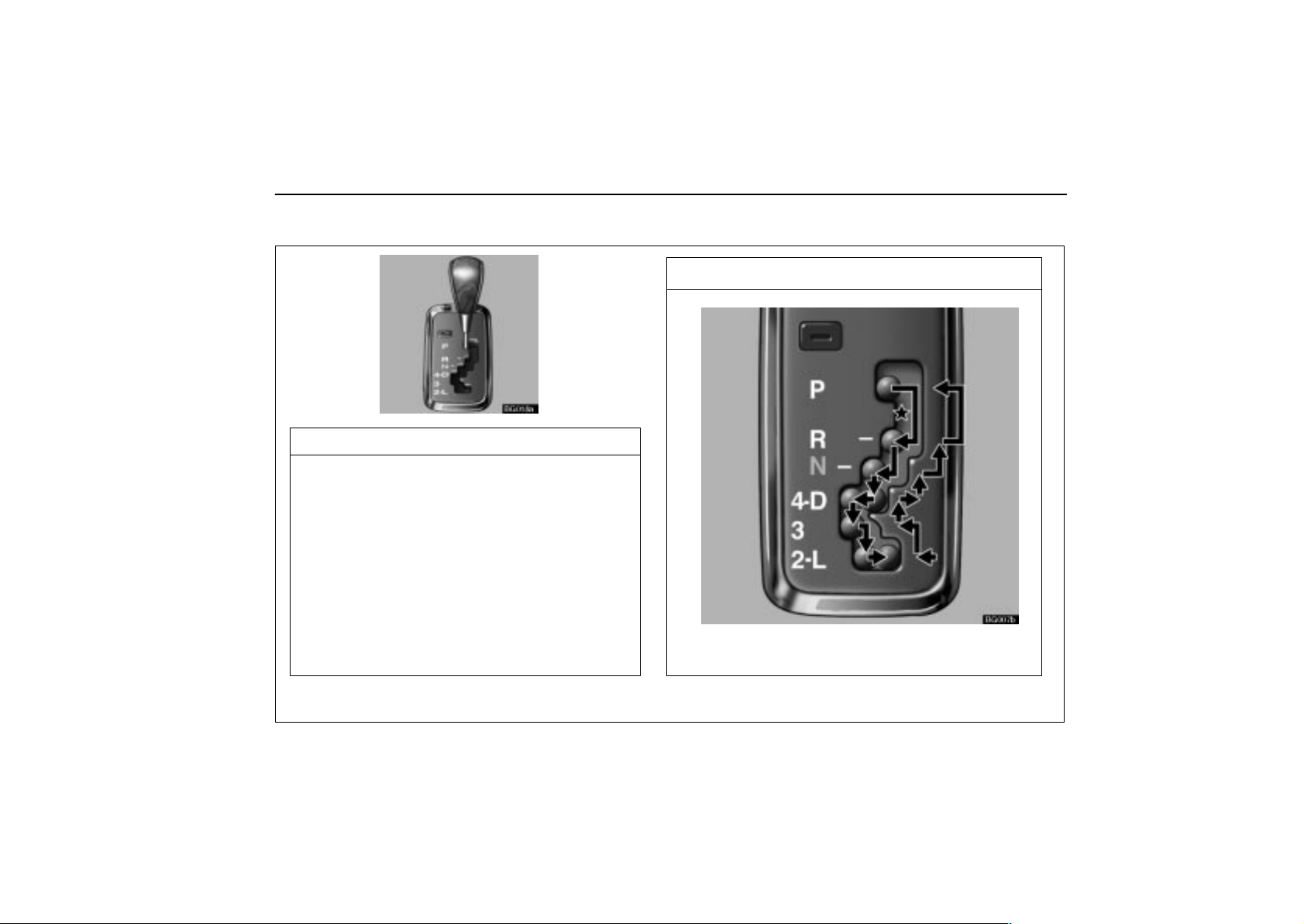
3. AUTOMATIC TRANSMISSION(GS430)
BG018a
SELECTOR LEVER POSITION
P: Parking, engine starting and key removal
R: Reverse
N: Neutral
D: Normal driving (with overdrive on)
4: Engine braking*
3, 2: Stronger engine braking
L: Maximum engine braking
QUICK REFERENCE
OPERATION OF SELECTOR LEVER
BG007b
Shift while pressing the brake pedal. (Ignition
switch must be in the ”ON” position.)
*When the cruise control is being used, even if you downshift from ”D” to “4”, engine braking will not be enabled because
the cruise control is not cancelled. For the operation to decrease the vehicle speed, see page 192.
3
Page 21
QUICK REFERENCE
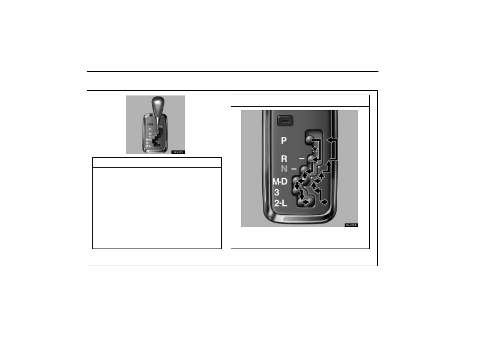
AUTOMATIC TRANSMISSION(GS300)
BG023
SELECTOR LEVER POSITION
P: Parking, engine starting and key removal
R: Reverse
N: Neutral
D: Normal driving (with overdrive on)
M: Manual shifting up or down shifting*
3, 2: Stronger engine braking
L: Maximum engine braking
OPERATION OF SELECTOR LEVER
BG020b
Shift while pressing the brake pedal. (Ignition
switch must be in the ”ON” position.)
*When the cruise control is being used, even if you downshift from ”D” to “4”, engine braking will not be enabled because
the cruise control is not cancelled. For the operation to decrease the vehicle speed, see page 192.
4
Page 22
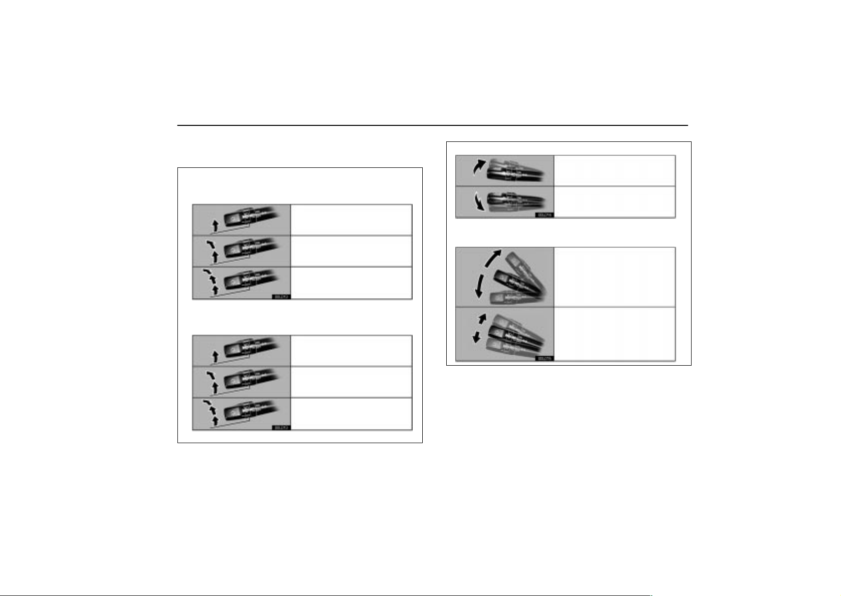
4. HEADLIGHT AND TURN SIGNAL
SWITCHES
HEADLIGHT SWITCH
With the ignition OFF
Parking, tail, license plate,
side marker and instrument
panel lights turn on.
Headlights also turn on.
00L013
Automatic light control
With the engine started and parking brake
released
Parking, tail, license plate,
side marker and instrument
panel lights turn on.
Headlights also turn on
00L013
at full intensity.
High beam
00L014
TURN SIGNAL SWITCH
Headlight flasher
Right or left turn
00L015
Lane change
(Right or left)
QUICK REFERENCE
Automatic light control
5
Page 23
QUICK REFERENCE
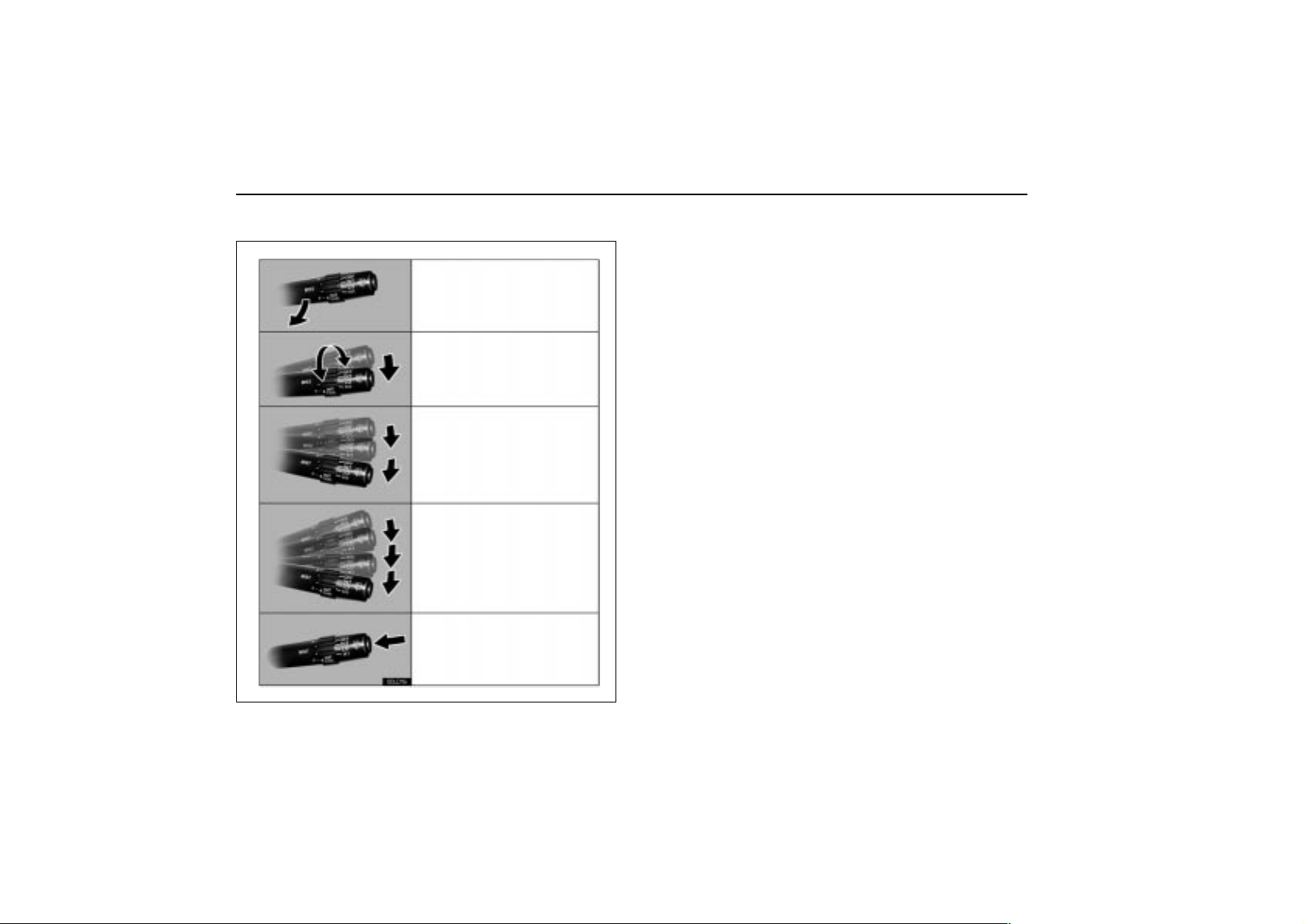
5. WIPER SWITCH
00L016
Mist wiper operation
Intermittent operation
Low speed operation
High speed operation
Washer on
6
Page 24

SECTION 1 –
INSTRUMENTS AND CONTROLS
Keys and doors
Keys 8. . . . . . . . . . . . . . . . . . . . . . . . . . . . . . . . . . . . . . . . . . . . . . . . . . . . .
Engine immobiliser system 11. . . . . . . . . . . . . . . . . . . . . . . . . . . . . . . . .
Wireless remote control 13. . . . . . . . . . . . . . . . . . . . . . . . . . . . . . . . . . . .
Doors 19. . . . . . . . . . . . . . . . . . . . . . . . . . . . . . . . . . . . . . . . . . . . . . . . . . .
1
7
Page 25
KEYS AND DOORS
KEYS
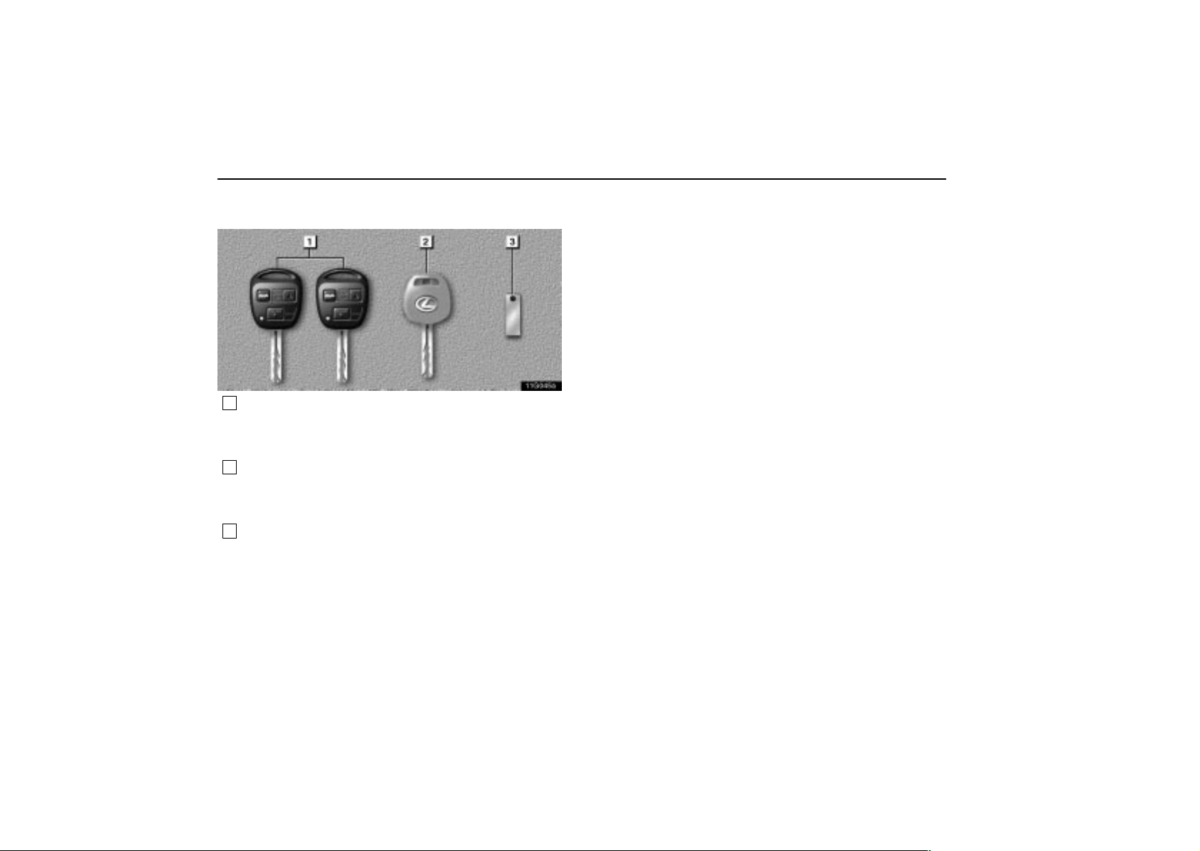
11g045a
1
Master keys (black) – These keys work in every lock.
For your Lexus dealer to make a new key with a
built–in transponder chip, your dealer will need one
of them.
2
Sub key (gray) – This key will not open the trunk,
trunk main switch and the glove box. For your Lexus
dealer to make a new key with built–in transponder
chip, your dealer will need it.
3
Key number plate – Keep the plate in a safe place
such as your wallet, not in the vehicle.
A transponder chip for the engine immobiliser system has
been placed in the head of the master and sub keys. These
chips are required for the system to function correctly, so be
careful not to lose these keys. If you make your own duplicate
key, you will not be able to cancel the system or start the
engine.
To protect items locked in the trunk or glove box when using
valet parking, leave the sub key with the attendant.
Since the doors and trunk lid can be locked without a key , you
should always carry a spare master key in case you
accidentally lock your keys inside the vehicle.
If you should lose your keys or if you need additional keys,
duplicates can be made by a Lexus dealer using the key
number.
We recommend writing down the key number and storing it in
a safe place.
8
Page 26
KEYS AND DOORS
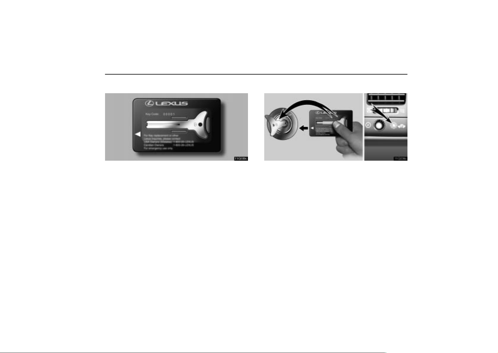
Flat key
11g039c
As a transponder chip is built in its key case, you can start
the engine with this key.
The flat key works in every lock.
A transponder chip for the engine immobiliser system has
been placed in the key case of the flat key. This chip is required
for the system to function correctly, so be careful not to lose this
key. If you make your own duplicate key, you will not be able
to cancel the system or start the engine.
Insert your key plate in its key case as shown. We recommend
that you always carry this with you for emergency use. Do not
leave it in your vehicle.
Starting the engine using a flat key
11g036c
1. Remove the key plate from the key case.
2. Insert the key plate into the ignition switch. The indicator
light keeps flashing.
3. Bring the key case closer to the ignition switch within 10
seconds as indicated by the arrow head. The indicator light
goes out. This means the engine immobiliser system is
automatically canceled. (For details, see “Engine immobiliser
system” on page 1 1.) You can put the key case away then. You
cannot cancel the engine immobiliser system if 10 seconds
have passed after you inserted the key plate. You need to
remove the key plate from the ignition switch and try it again
from the step 2.
4. Start the engine within 60 seconds after the security
indicator light goes out. You cannot start the engine if 60
seconds have passed after the security indicator went off. You
need to remove the key plate from the ignition switch and try
it again from the step 2.
9
Page 27
KEYS AND DOORS
NOTICE
Do not let the key case become bent as the key plate
may fall out or become bent also.
The flat key is designed for emergency use only. So
do not use it regularly instead of other master keys.
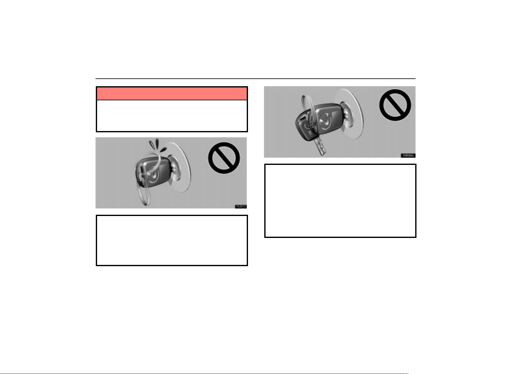
11L021-2
When using a key containing a transponder chip,
observe the following precautions:
When starting the engine, do not use the key with a
key ring resting on the key grip and do not press the
key ring against the key grip. Doing so may prevent
the engine from starting, or may cause the engine to
stop soon after it starts.
11R055
When starting the engine, do not use the key in
proximity with other transponder keys (including the
flat key and keys of other vehicles), and do not press
other key plates against the key grip. Doing so may
prevent the engine from starting, or may cause the
engine to stop soon after it starts. If this happens,
remove the key once and then insert it again after
removing other transponder keys (including the flat
key and keys of other vehicles) from the ring or while
gripping or covering them with your hand to start the
engine.
10
Page 28
11G035c
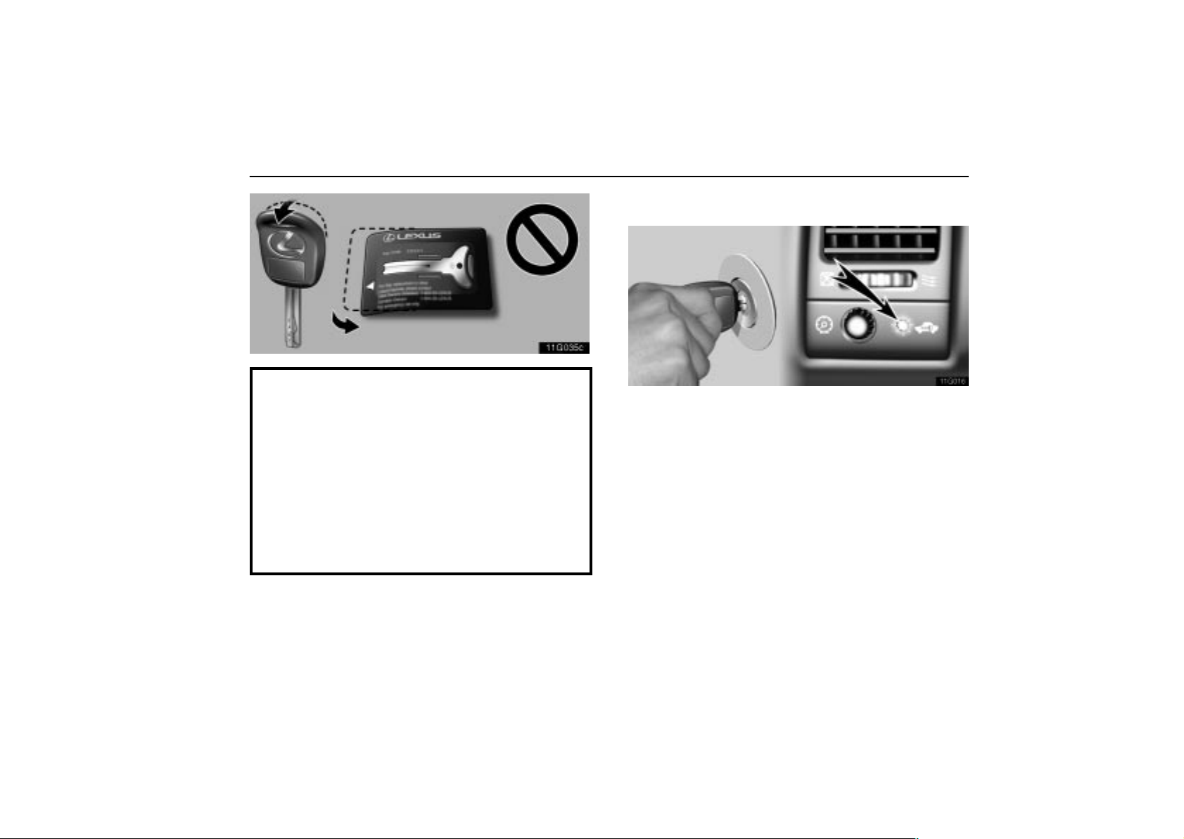
Do not bend the key grip or flat key.
Do not cover the key grip or flat key with any material
that cuts off electromagnetic waves.
Do not knock the key or flat key hard against other
objects.
Do not leave the key or flat key exposed to high
temperatures for a long period, such as on the
dashboard or hood under direct sunlight.
Do not put the key or flat key in water or wash it in an
ultrasonic washer.
Do not use the key or flat key with electromagnetic
materials.
KEYS AND DOORS
ENGINE IMMOBILISER SYSTEM
w11L016
The engine immobiliser system is a theft prevention
system. When you insert the key in the ignition switch, the
transponder chip in the key’s head transmits an electronic
code to the vehicle. The engine will start only when the
electronic code in the chip corresponds to the registered
ID code for the vehicle.
The system is automatically set when the key is removed from
the ignition switch. At this time, the security indicator light
flashes. When you insert the key in the ignition switch, the
security indicator light goes out and the system is canceled
automatically, which enables the engine to start.
The transponder chip of the flat key is in its key case. You can
cancel the engine immobiliser system using the flat key . (For
details, see “Flat key” on page 9.)
11
Page 29
KEYS AND DOORS
For your Lexus dealer to make you a new key with built–in
transponder chip, your dealer will need your key number and
master key or the flat key. However, there is a limit to the
number of additional keys your Lexus dealer can make for you.
If you make your own duplicate key, you will not be able
to cancel the system or start the engine.
For vehicles sold in U.S.A.
FCC ID: MOZ RI–4ATY
MADE IN JAPAN
This device complies with Part 15 of the FCC Rules.
Operation is subject to the following two conditions:
(1) This device may not cause harmful interference,
and (2) this device must accept any interference
received, including interference that may cause
undesired operation.
CAUTION
Changes or modifications not expressly approved by
the party responsible for compliance could void the
user’s authority to operate the equipment.
For vehicles sold in Canada
This device complies with RSS–210 of Industry
Canada. Operation is subject to the following two
conditions:
(1) This device may not cause interference, and (2)
this device must accept any interference, including
interference that may cause undesired operation of the
device.
12
Page 30
KEYS AND DOORS
WIRELESS REMOTE CONTROL*
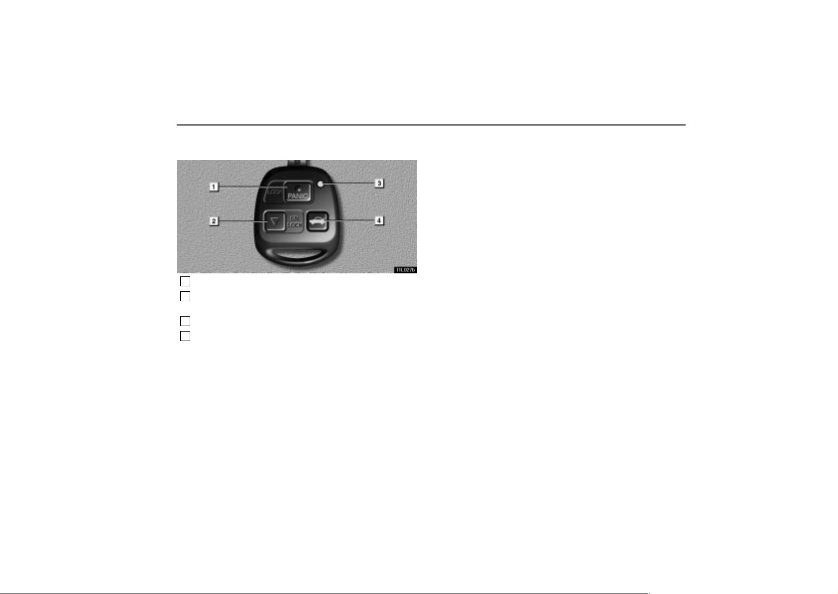
11L027b
1
Locking the doors and sounding an alarm
2
Unlocking the doors and opening the windows and
moon roof
3
Indicator light
4
Unlocking the trunk lid
NOTE: *This feature can be deactivated as vehicle theft
deterrent measure in case of the loss of the wireless remote
control key. Ask your Lexus dealer for details.
When you operate any button on the key, push it slowly and
surely. At this time, the indicator light on the key grip flashes
once.
The operational range of the wireless remote control is
approximately 1 meter (3 ft.). The effective range may vary
with different conditions. To activate the wireless remote
control without fail, do it approximately 1 meter (3 ft.) from your
Lexus.
In the following cases, the battery in the key may be
discharged. If this is the case, replace it using a special
screwdriver.
The remote control does not work.
The operational range of wireless remote control becomes
extremely short.
The indicator light on the key is dimmed or does not come
on.
For the replacement of the battery, see ”Replacing the battery”
on page 17. You can also have the battery of the key replaced
by your Lexus dealer.
If you lose the wireless key, contact your Lexus dealer as soon
as possible to avoid the possibility of theft, or an accident.
Y ou can use up to 4 wireless remote control keys for the same
vehicle. Contact your Lexus dealer for detailed information.
The wireless remote control key is an electronic
component. Observe the following instructions in order
not to cause damage to the key.
Do not leave the wireless remote control key on places
where the temperature becomes high such as on the
dashboard.
Do not disassemble it.
Avoid knocking it hard against other objects or dropping it.
Avoid putting it in water.
13
Page 31
KEYS AND DOORS
Locking/Unlocking the doors
When you push the ”LOCK” button on the key briefly, all
the doors can be locked from outside the vehicle.
When they are locked securely, the emergency flashers will
flash and one beep will sound.* However, when you push the
”LOCK” button with any door not closed securely, the buzzer
sounds for 10 seconds.** To stop the buzzer, close all the
doors securely or push the ”UNLOCK” button. If the key is in
the ignition switch, locking cannot be done.
Make sure all the doors are locked when you leave the vehicle.
Push the ”LOCK” button once again. If they were already
locked, the turn signal lights will flash.***
NOTE: *The emergency flashers can be set not to flash and
beep volume can be changed. **The buzzer can be set not
to sound if a door is not closed securely. ***The turn signal
lights can be set not to flash. Ask your Lexus dealer for
details.
NOTICE
Do not push the ”LOCK” button any longer than 2 to 3
seconds. Pushing the button longer activates an alarm.
For details, see page 15.
When you push the ”UNLOCK” button, the driver’s door
is unlocked. Pushing that button once again within 3
seconds from the first push, all other doors are also
unlocked.*
NOTE: *The 2–step unlocking function can be changed.
Ask your Lexus dealer for details.
14
At this time, the emergency flashers will flash twice and two
beeps will sound.* Together with the activation of unlocking,
the interior light comes on for 15 seconds if the interior light
switch is in ”DOOR” position.** However, this function does
not work when the ignition key is in the ”ON” position. For
further information, see ”Interior lights” on page 53.
You have 30 seconds to open a door after using the wireless
remote unlock feature.*** If a door is not opened by then, all
the doors will be automatically locked again.
Even if the ”LOCK” or ”UNLOCK” button is kept pressed in, the
locking or unlocking operation is not repeated. Release the
button and then push again.
NOTE: *The emergency flashers can be set not to flash and
beep volume can be changed. **The interior light can be set
not to come on or the duration of lighting can be changed.
***The time before automatic re–locking can be changed.
Ask your Lexus dealer for details.
Page 32
KEYS AND DOORS
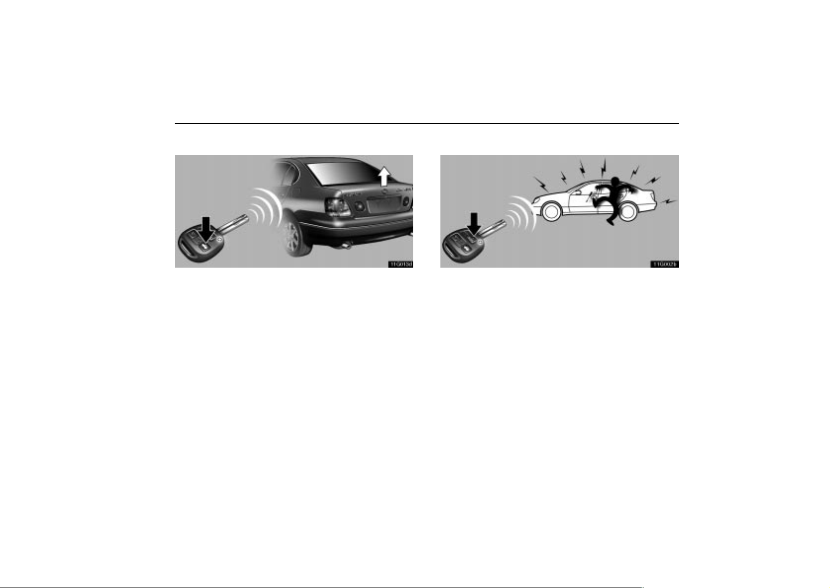
Unlocking the trunk lid
11G013d
When you keep the button pushed for about 1 second, you
can unlock the trunk lid.* One beep sounds.
This function does not work when the ignition key is in the ”ON”
position.
NOTE: *The operation method can be changed. Ask your
Lexus dealer for details.
Sounding an alarm*
11G002b
When you push the ”PANIC” button for about 2 to 3
seconds, an alarm sounds to deter any person trying to
break into or damage your vehicle.
If you want to stop the alarm, push any button.
This function does not work when the ignition key is in the ”ON”
position.
NOTE: *The alarm can be set not to sound. Ask your Lexus
dealer for details.
15
Page 33
KEYS AND DOORS
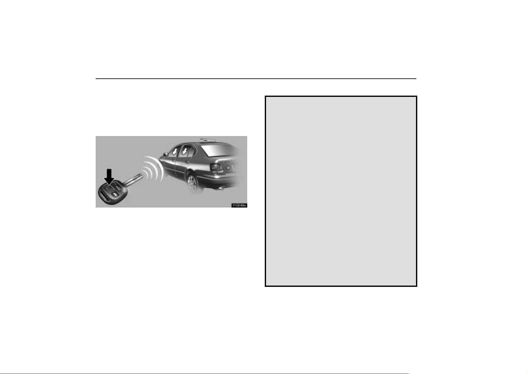
Operating the windows and moon roof
The windows and moon roof can be operated using a
wireless key from outside the vehicle.*
NOTE: *The windows can be deactivated. The moon roof
can be set to slide open, tilt up or deactivated. Ask your
Lexus dealer for details.
11G048a
Push the ”UNLOCK” button until the windows and moon roof
start to move. When you release the button, the windows and
moon roof stop operating.
This function will work even with the window lock switch
pressed in.
For vehicles sold in U.S.A.
This device complies with Part 15 of the FCC Rules.
Operation is subject to the following two conditions: (1)
This device may not cause harmful interference, and (2)
this device must accept any interference received,
including interference that may cause undesired
operation.
NOTICE:
This equipment has been tested and found to comply
with the limits for a Class B digital device, pursuant to
Part 15 of the FCC Rules. These limits are designed to
provide reasonable protection against harmful
interference in a residential installation. This equipment
generates, uses and can radiate radio frequency
energy and, if not installed and used in accordance with
the instructions, may caus e harmful interference to
radio communications. However, there is no guarantee
that interference will not occur in a particular
installation. If this equipment does cause harmful
interference to radio or television reception, which can
be determined by turning the equipment off and on, the
user is encouraged to try to correct the interference by
one or more of the following measures:
Reorient or relocate the receiving antenna.
Increase the separation between the equipment and
receiver.
Connect the equipment into an outlet on a circuit differ-
ent from that to which the receiver is connected.
16
Page 34
KEYS AND DOORS
Consult the dealer or an experienced radio / TV techni-
cian for help.
FCC WARNING:
Changes or modifications not expressly approved
by the party responsible for compliance could void
the user’s authority to operate the equipment.
For vehicles sold in Canada
Operation is subject to the following two conditions: (1)
this device may not cause interference, and (2) this
device must accept any interference, including
interference that may cause undesired operation of the
device.
Replacing the battery
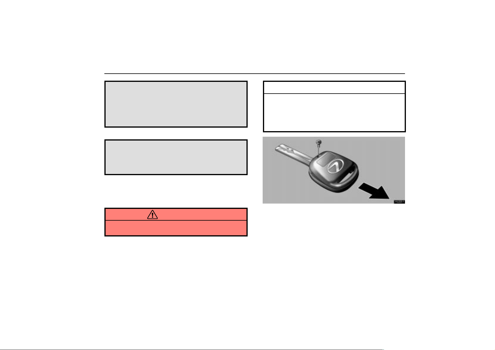
When you replace the battery, prepare a lithium battery
CR1616 or equivalent and a special screwdriver.
CAUTION
Special care should be taken to prevent small children
from swallowing the removed battery or components.
NOTICE
When replacing the battery, be careful not to lose the
components, screws and O–ring.
Replace only with the same or equivalent type
recommended by a Lexus dealer.
Dispose of used batteries according to the local laws.
11L028–1
1. Remove the screw, and then the cover while pushing it in the
arrow direction.
17
Page 35
KEYS AND DOORS
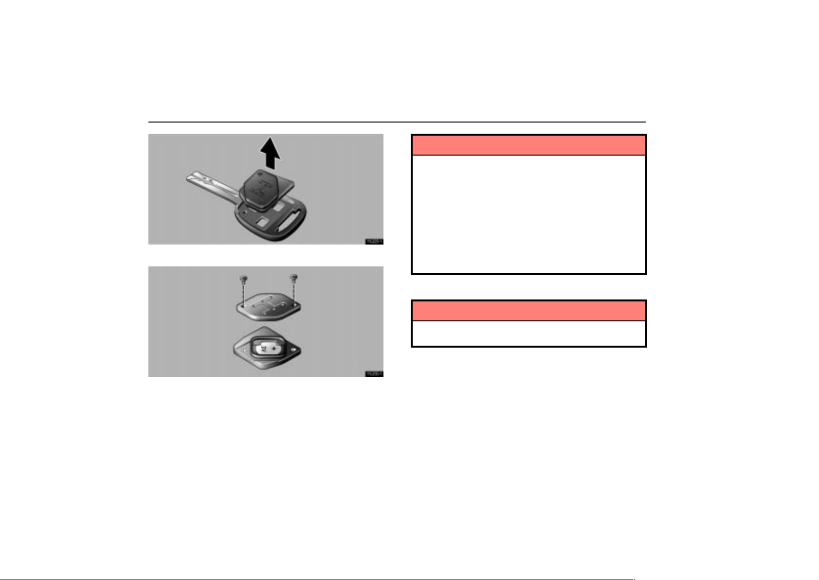
11L029–1
2. Remove the module from the key frame.
11L030–1
3. Remove the 2 screws to take out the lid of the module.
4. Take out the discharged battery and put a new battery with
the positive side up.
NOTICE
Make sure the positive side and negative side of the
battery are faced correctly.
Do not replace the battery with wet hands. Water may
cause unexpected rust.
Do not touch or move any components inside the
transmitter, or it may interfere with proper operation.
Be careful not to bend the electrode of the battery
insertion and that dust or oils do not adhere to the
inside of the module.
Take care not to lose the screws and O–ring.
5. Install the lid with the 2 screws.
NOTICE
Take care not to damage or bend the O–ring when
installing.
6. Install the module into the key frame and secure the cover
with the screw.
7. When pushing any switch on the wireless key, make sure
the indicator light comes on.
18
Page 36
KEYS AND DOORS
DOORS
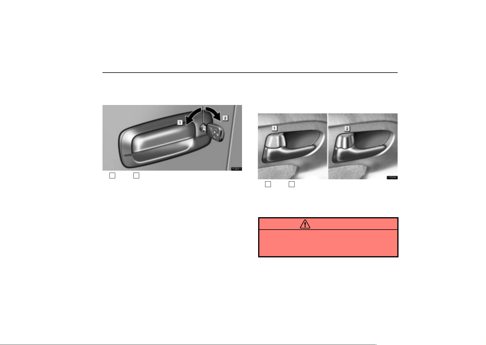
Locking with key
11G003–1
1
Lock 2Unlock
Turn the key towards the front of the vehicle to lock and
towards the back to unlock.
The doors lock and unlock simultaneously with either front
door. I n the driver’s door lock, turning the key once will unlock
the driver’s door and twice in succession will unlock all doors
simultaneously .* I n the passenger’s door lock, turning the key
once will unlock all doors simultaneously.
NOTE: *The 2–step unlocking function can be changed.
Ask your Lexus dealer for details.
If a wrong key is used, the key cylinder rotates freely to isolate
inside mechanism. So, door locking is protected from thieves.
The windows and moon roof can be opened and closed from
outside the vehicle using the key. For details, see “Power
window switches” on page 32 and “Moon roof” on page 70.
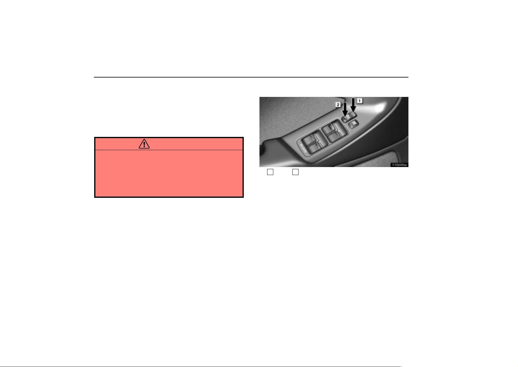
Locking with inside lock button
11G004
1
Lock 2Unlock
Push in the lock button to lock and unlock the door.
The front doors can be opened by pulling the inside handles
even if the lock buttons are in the locked position.
CAUTION
Do not pull the inside handle of the front doors while
driving. The doors will open and an accident may occur.
Lexus strongly recommends that all children be placed
in the rear seat of the vehicle.
19
Page 37
KEYS AND DOORS
Closing the door with the lock button pushed in will also lock
the door. Be careful not to lock your keys in the vehicle. Doors
cannot be locke d when either front door is open and the key is
in the ignition.
If the vehicle is subjected to a severe frontal, rear or side
impact with the ignition switch turned to the “ON” position, all
the doors will unlock automatically after a few seconds.
CAUTION
Before driving, make sure the doors are closed and
locked, especially when small children are in the
vehicle. Along with the proper use of seat belts, locking
the doors helps prevent the driver and passengers from
being thrown out from the vehicle during an accident.
It also helps prevent the doors from being opened
unintentionally.
Locking with power door lock switch
11G005a
1
Lock 2Unlock
To lock all the doors simultaneously, push the power door
lock switch down on the front side. Pushing down on the
rear side will unlock them.
The same switch is also found on the front passenger’s side.
Auto door locking function*: All t he do ors wil l loc k
automatically when the selector lever is moved out of “P”
position. This auto door locking function is operable while the
ignition switch is turned to the “ON” position.
NOTE: * This auto door locking function can be disabled or
changed. Ask your Lexus dealer for details.
20
Page 38
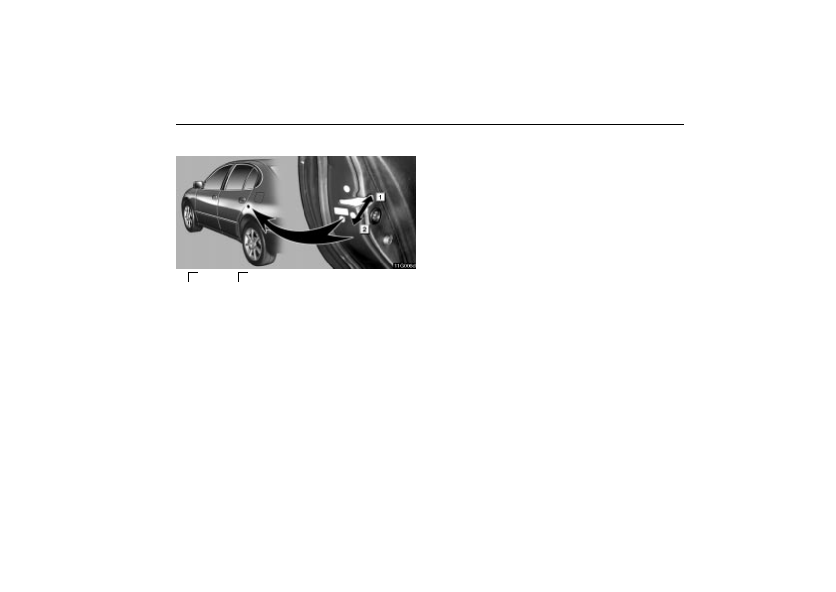
Locking with rear door child–protector
11G006d
1
Unlock 2Lock
Whenever small children are in the vehicle, lock the rear
door so that it does not open from the inside. T o do this,
turn the knob to the ”LOCK” position as shown and then
close the door.
KEYS AND DOORS
21
Page 39

KEYS AND DOORS
22
Page 40

SECTION 1 –
INSTRUMENTS AND CONTROLS
Switches
Headlight switch 24. . . . . . . . . . . . . . . . . . . . . . . . . . . . . . . . . . . . . . . . . .
Headlight dimmer and turn signal switches 26. . . . . . . . . . . . . . . . . . .
Fog light switch 27. . . . . . . . . . . . . . . . . . . . . . . . . . . . . . . . . . . . . . . . . . .
Windshield wiper and washer switches 28. . . . . . . . . . . . . . . . . . . . . . .
Headlight cleaner switch 30. . . . . . . . . . . . . . . . . . . . . . . . . . . . . . . . . . .
Rear window and outside rear view mirror defogger switch 31. . . . .
Power window switches 32. . . . . . . . . . . . . . . . . . . . . . . . . . . . . . . . . . . .
Emergency flasher switch 35. . . . . . . . . . . . . . . . . . . . . . . . . . . . . . . . . .
Seat heater switches 35. . . . . . . . . . . . . . . . . . . . . . . . . . . . . . . . . . . . . .
2
23
Page 41
SWITCHES
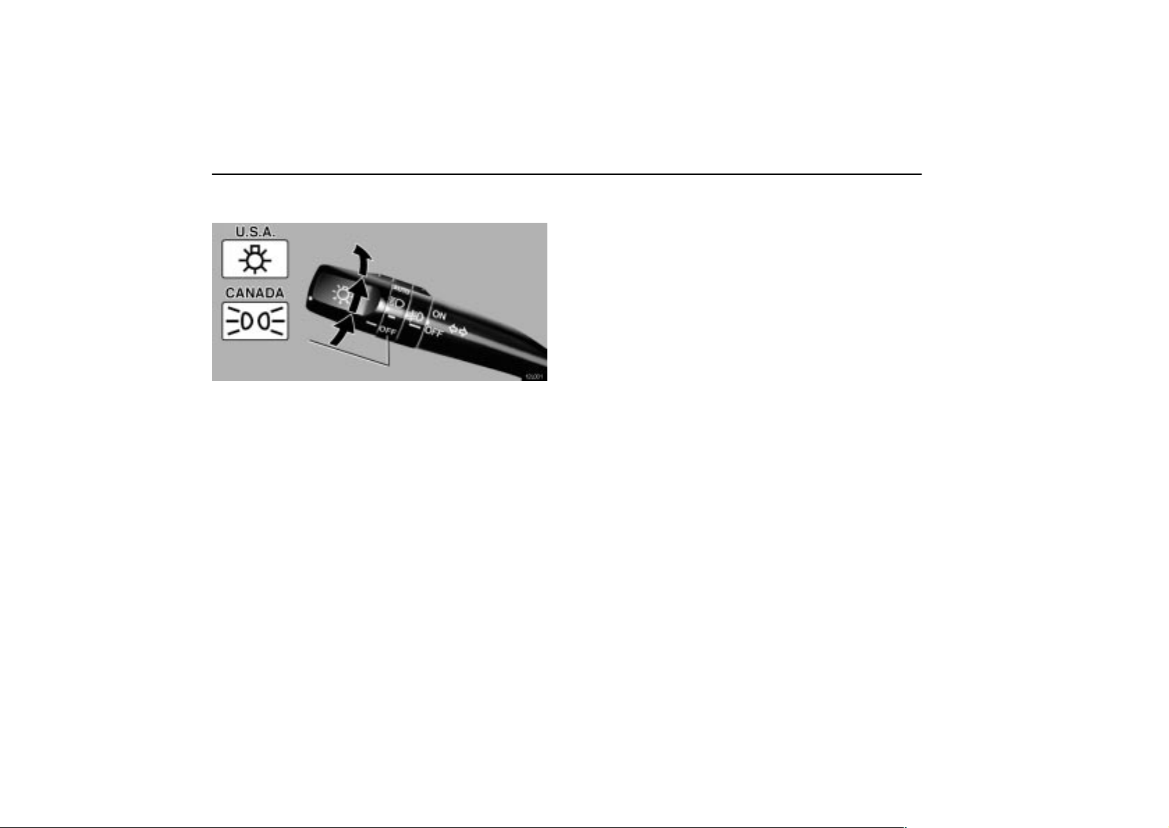
HEADLIGHT SWITCH
12L001
To turn the lights on, twist the knob on the end of the lever .
FIRST CLICKSTOP: Only the parking, tail, license plate, side
marker and instrument panel lights turn on.
SECOND CLICKSTOP: Headlights also turn on.
THIRD CLICKSTOP (”AUTO”): The headlights and all other
lights automatically turn on depending on the darkness of the
surroundings.*
Vehicles sold in U.S.A.: When the headlights are on, the
headlight indicator lights up in the instrument cluster.
Vehicles sold in Canada: When the tail lights are on, the tail
light indicator lights up in the instrument cluster.
Manually twist the knob to the second clickstop to turn on
the headlights if they are needed immediately when
entering a dark tunnel, parking structure, etc.
When the headlight switch is turned to the first or second
clickstop, the brightness of the instrument cluster will be
reduced slightly unless the instrument panel light control knob
is turned fully on.
NOTE: *The operating condition or sensitivity can be
changed. Ask your Lexus dealer for details.
24
Page 42
12G001
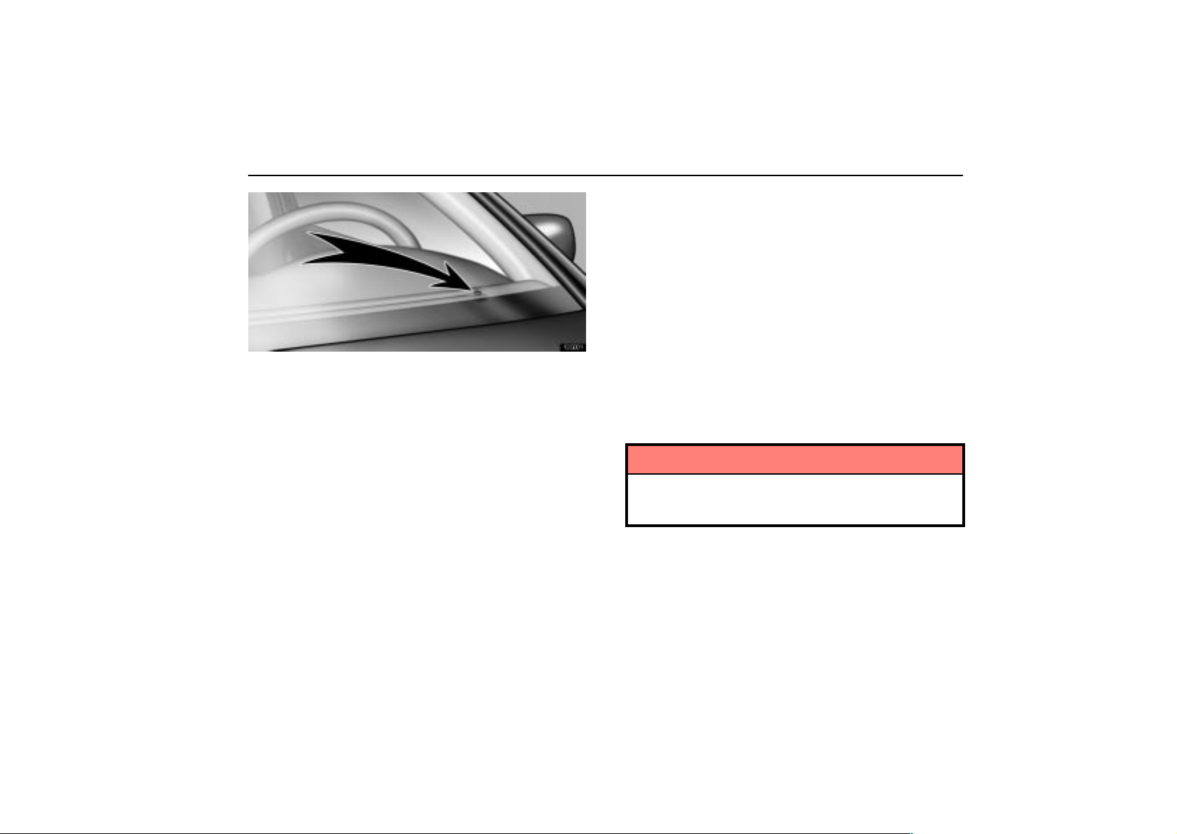
The automatic light control sensor is on top of the driver’s side
instrument panel.
Do not place anything on the instrument panel, and/or do not
affix anything on the windshield to block this sensor.
When the headlights come on, the lights automatically turn off
about 30 seconds after any of the doors is opened and closed
with the ignition key turned to the ”ACC” or ”LOCK” position.*
T o turn them on again, turn the ignition key to the ”ON” position,
or turn the headlight switch off and then twist the knob until the
first or second clickstop. If you are going to park for over one
week, make sure the headlight switch is off.
When the headlight switch is on with all the doors locked,
pushing the ”LOCK” button on the wireless remote control key
turns off the headlights.
NOTE: *The time before turning off the lights can be
changed. Ask your Lexus dealer for details.
SWITCHES
Daytime Running Light System
The headlights turn on at reduced intensity when the parking
brake is released with the engine started, even with the light
switch in the ”OFF” position. They will not go off until the
ignition switch is turned off.
To turn on the other exterior lights and instrument panel lights,
twist the knob to the first clickstop.
Twist the knob to the second clickstop to turn on the headlights
to full intensity for driving at night.
When setting the knob to the third clickstop (”AUTO”), the
headlights will automatically adjust to full intensity and/or turn
on the other lights depending on the darkness of the
surroundings. Likewise, as the surroundings become brighter,
the headlights will turn to reduced intensity, ultimately turning
off the other lights.
NOTICE
To prevent the battery from being discharged, do not
leave the lights on longer than necessary when the
engine is not running.
25
Page 43
SWITCHES
Automatic headlight leveling system
(Vehicles with discharge headlight only)
12G012
The headlight beam level is always maintained automatically
at the proper level in all loading conditions so that your
headlights do not dazzle other road users.
If this system fails, the warning light in the instrument cluster
comes on. If this occurs, have your vehicle checked by Lexus
dealer.
HEADLIGHT DIMMER AND TURN
SIGNAL SWITCHES
12L003
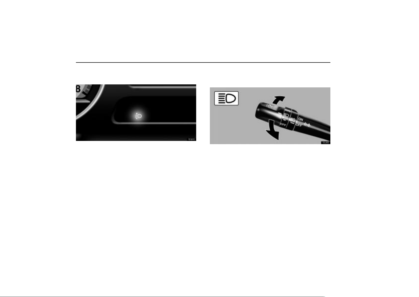
For high beam, push the lever forward. Pull it back for low
beam. For the headlight flasher, pull it further back.
A blue light in the instrument cluster indicates high beam or
headlight flasher is on.
The headlight flasher works even when the headlight switch is
off.
26
Page 44
12L004
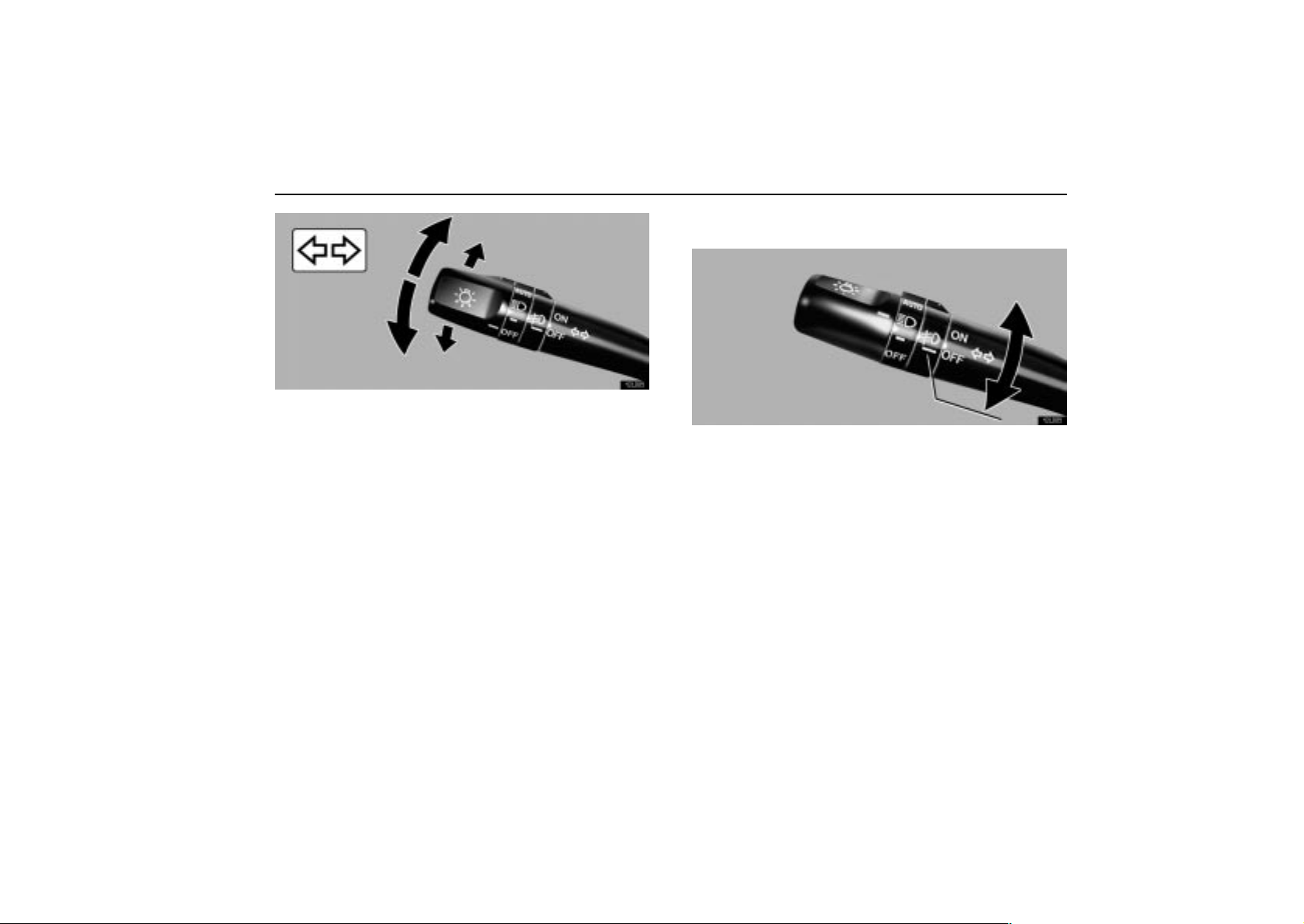
For signaling turns, move the lever up or down in the
conventional manner.
The ignition key must be in the ”ON” position.
The turn signal is self–cancelling after a turn, but after a lane
change, you may have to cancel it by hand. You can also signal
a lane change by moving the turn signal lever partway and
holding it there.
If the green light in the instrument cluster flashes faster than
normal, it indicates that the front or rear turn signal bulb has
burned out. If this indicator light does not come on, the fuse
or the indicator light itself has probably failed.
SWITCHES
FOG LIGHT SWITCH
12L005
To turn on the fog lights, turn the switch to the ”ON”
position. They will come on only when the headlights are
on low beam.
27
Page 45
SWITCHES
WINDSHIELD WIPER AND WASHER
SWITCHES
12L006–1
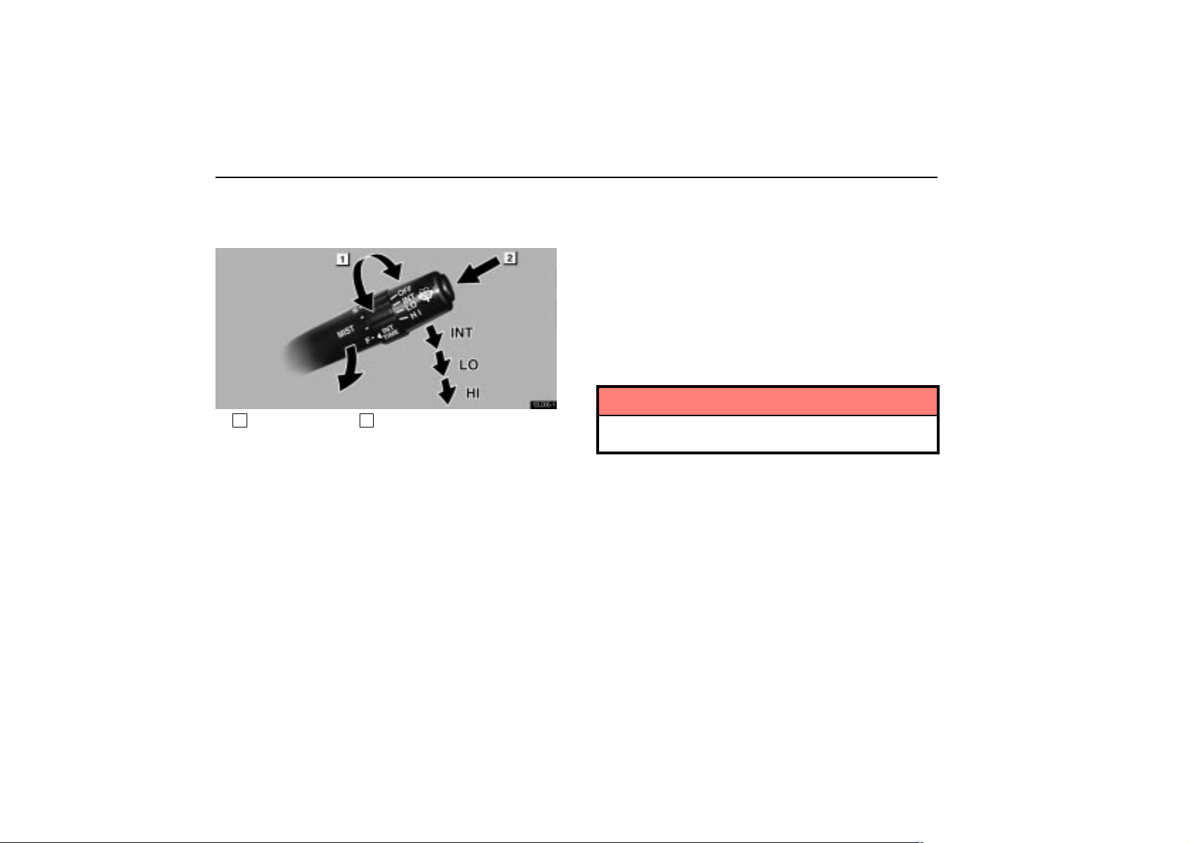
1
Interval adjuster 2Washer on
To turn the wipers on, move the lever down until you reach
the desired speed setting.
The ignition key must be in the ”ON” position.
There are 3 settings:
”INT” position: Intermittent operation
”LO” position: Low speed operation
”HI” position: High speed operation
T wist the interval adjuster upward to increase the wiping
time interval between sweeps, and downward to decrease
it.
The wiper lever must be in the ”INT” position.
For mist wiper operations (a single wipe), pull the lever
toward you and release it.
To make the washer squirt, push the button on the end of
the lever.
The low washer fluid warning light in the instrument cluster
comes on when the fluid level in the tank becomes very low.
For information on adding washer fluid, see ”Adding washer
fluid” on page 303.
In cold weather, warm the windshield with the defroster before
using the washer. This will help prevent icing, which could
block your vision.
NOTICE
Do not operate the wipers if the windshield is dry. It m a y
scratch the glass.
28
Page 46
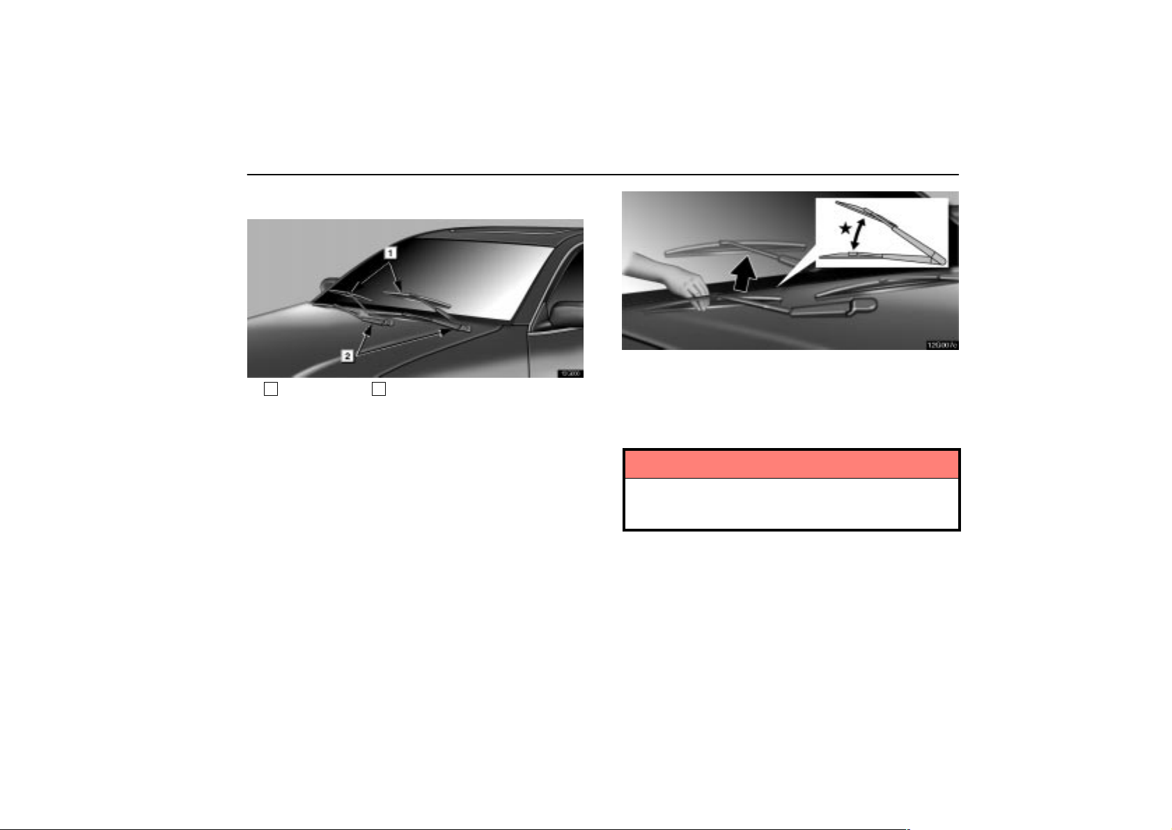
Shifting the windshield wiper position
12G006
1
Rest position 2Retracted position
The wiper blades retract under the hood when the wipers are
turned off.
In the following cases, the wipers should be shifted from the
retracted position to the rest position above the hood level.
When cleaning the windshield
When inspecting or replacing the wipers
When the retraction may be obstructed by snow., etc., at the
bottom of the windshield
Other than the above cases, keep the wipers in the retracted
position.
SWITCHES
12G007c
More than 10 cm (3.9 in.)
To shift the windshield wipers from retracted to rest
position, hold the connection of the wiper arm and wiper
blade and pull it upward along the windshield glass with
the force of about 98 N (10 kgf, 22 lbf.).
NOTICE
To prevent the wiper blades from being deformed, be
sure to hold the connection of the wiper arm and wiper
blade securely.
29
Page 47
SWITCHES
12G008b
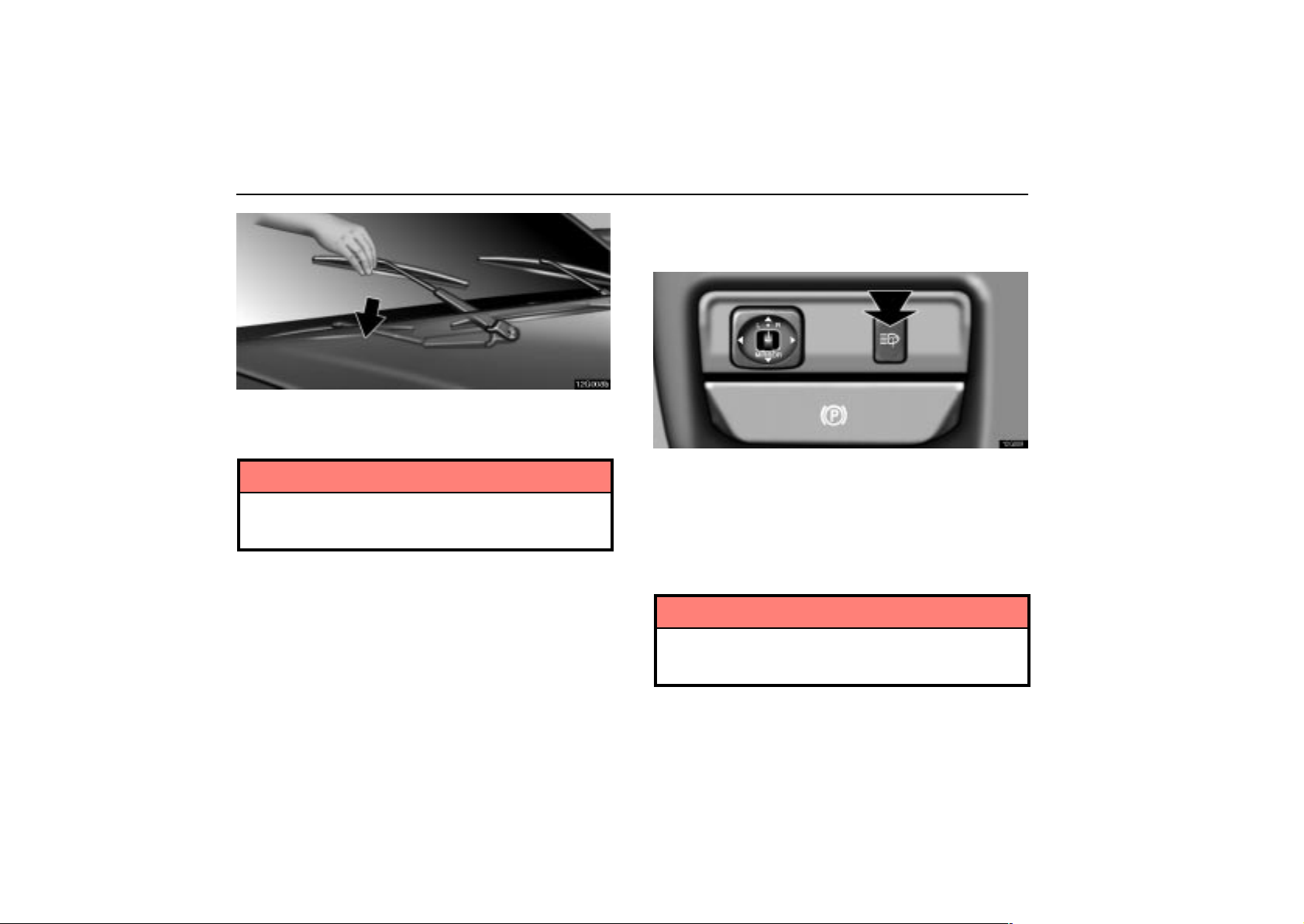
To return the windshield wipers to retracted position,
push the connection of the wiper arm and wiper blade
downward.
NOTICE
To prevent the wiper blades from being deformed, be
sure to hold the connection of the wiper arm and wiper
blade securely.
HEADLIGHT CLEANER SWITCH
(CANADA ONLY)
12G009
To spray fluid on the headlights, push the switch with the
headlights on.
The ignition key must be in the ”ON” position.
The low washer fluid warning light in the instrument cluster
comes on when the fluid level in the tank becomes very low.
For information on adding washer fluid, see ”Adding washer
fluid” on page 303.
NOTICE
30
Do not turn the headlight cleaner on with the washer
fluid tank empty. It may cause the cleaner motor to
overheat.
Page 48
SWITCHES
REAR WINDOW AND OUTSIDE
REAR VIEW MIRROR DEFOGGER
SWITCH
12G010
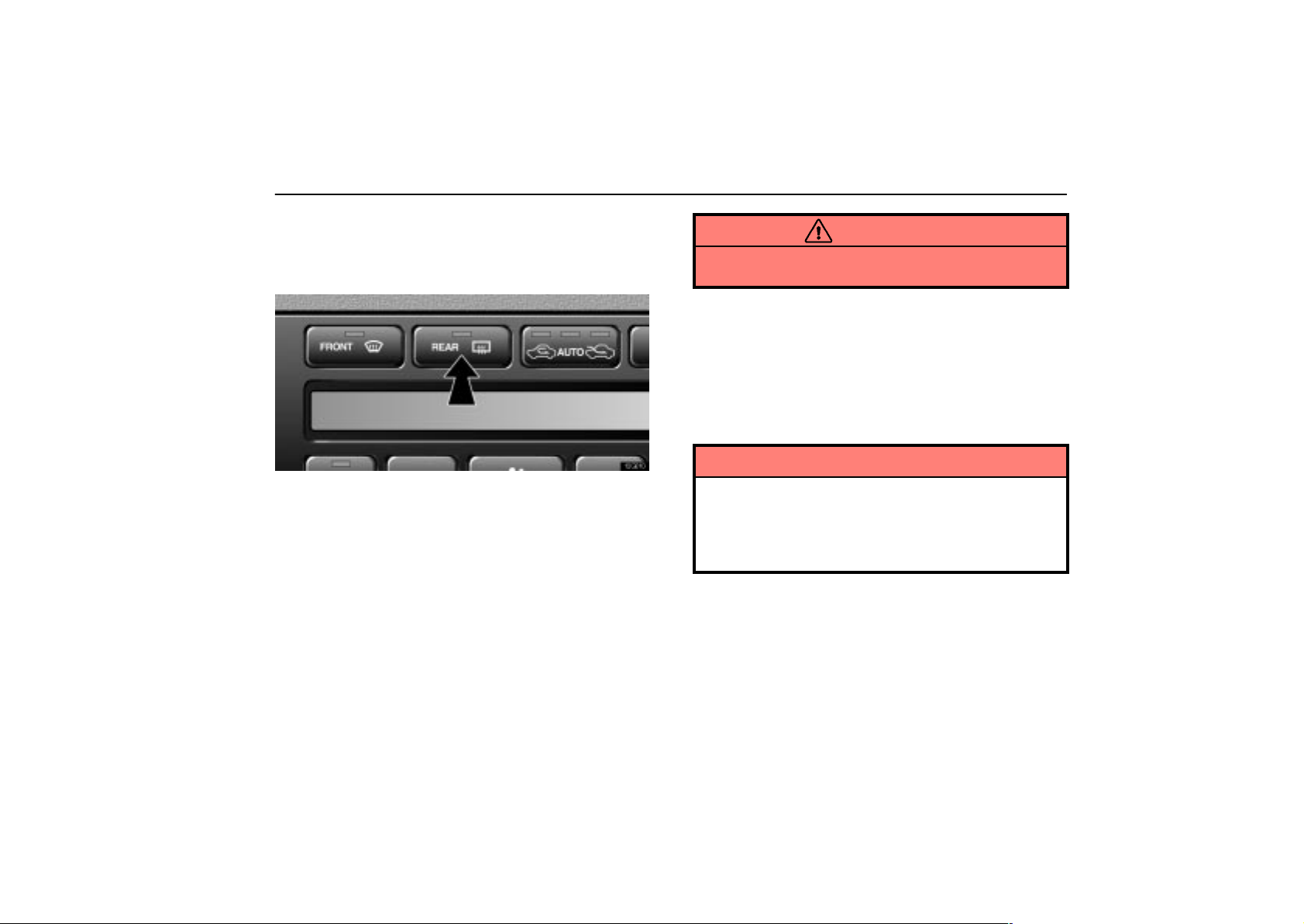
To turn the electric rear window defogger on, push the
switch.
The ignition key must be in the ”ON” position.
The thin heater wires on the inside of the rear window and the
heater panels in the outside rear view mirrors will quickly clear
the surface. Keep your hands off the mirror faces when the
switch is on. An indicator light is on when the defogger is
operating.
The system will automatically shut off when the defogger has
operated about 15 minutes.
CAUTION
Since the mirror surfaces can get hot, do not touch them
when the switch is on.
If further defrosting or defogging is desired, simply actuate the
switch again. When the surface has cleared, push the switch
once again to turn the defogger off. Continuous use may cause
the battery to discharge, especially during stop–and–go
driving. The defogger is not designed to dry rain water or to
melt snow.
If the outside rear view mirrors are heavily coated with ice, use
a spray de–icer before operating the switch.
NOTICE
When cleaning the inside of the rear window, be
careful not to scratch or damage the heater wires or
connectors.
To prevent the battery from being discharged, turn
the switch off when the engine is not running.
31
Page 49
SWITCHES
POWER WINDOW SWITCHES
12G003a
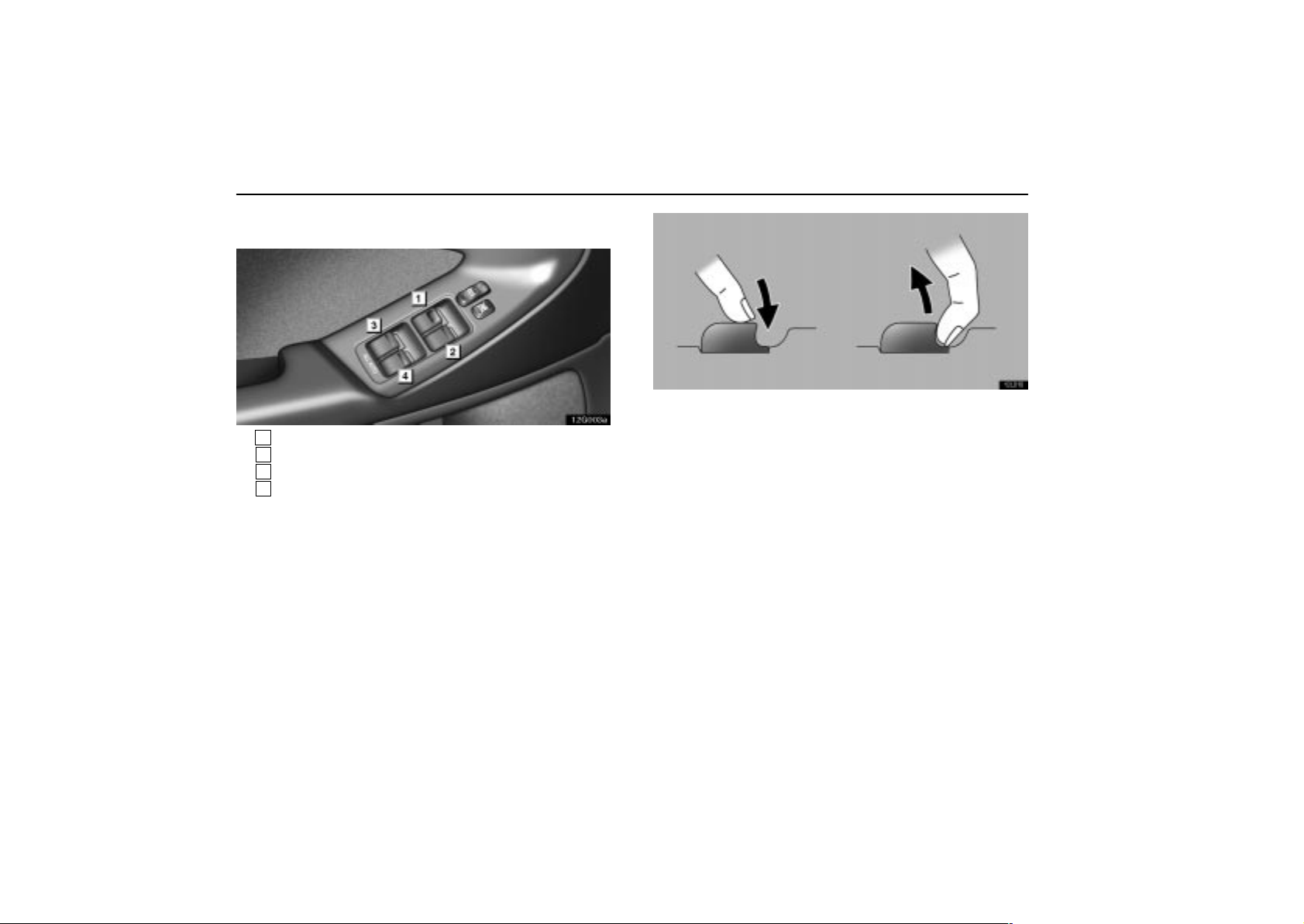
1
For driver’s window
2
For front passenger’s window
3
For left rear window
4
For right rear window
To raise or lower the windows, use the switch on each
door. The passengers’ windows can also be controlled by
the switches on the driver’s door.
The power windows work when the ignition key is in the ”ON”
position.
Key off operation: Even if the ignition key is turned to the
”ACC” or ”LOCK” position, the window can be operated until
any of the doors is opened (or for about 45 seconds).
12L010
Operating the switches
To raise or lower the window, pull the switch halfway up
or push it halfway down.
Automatic operation: To fully raise or lower the window
automatically, pull the switch fully up or push it fully down.
To stop the window partway, lightly push or pull the switch in
the opposite direction and then release it.
32
Page 50
SWITCHES
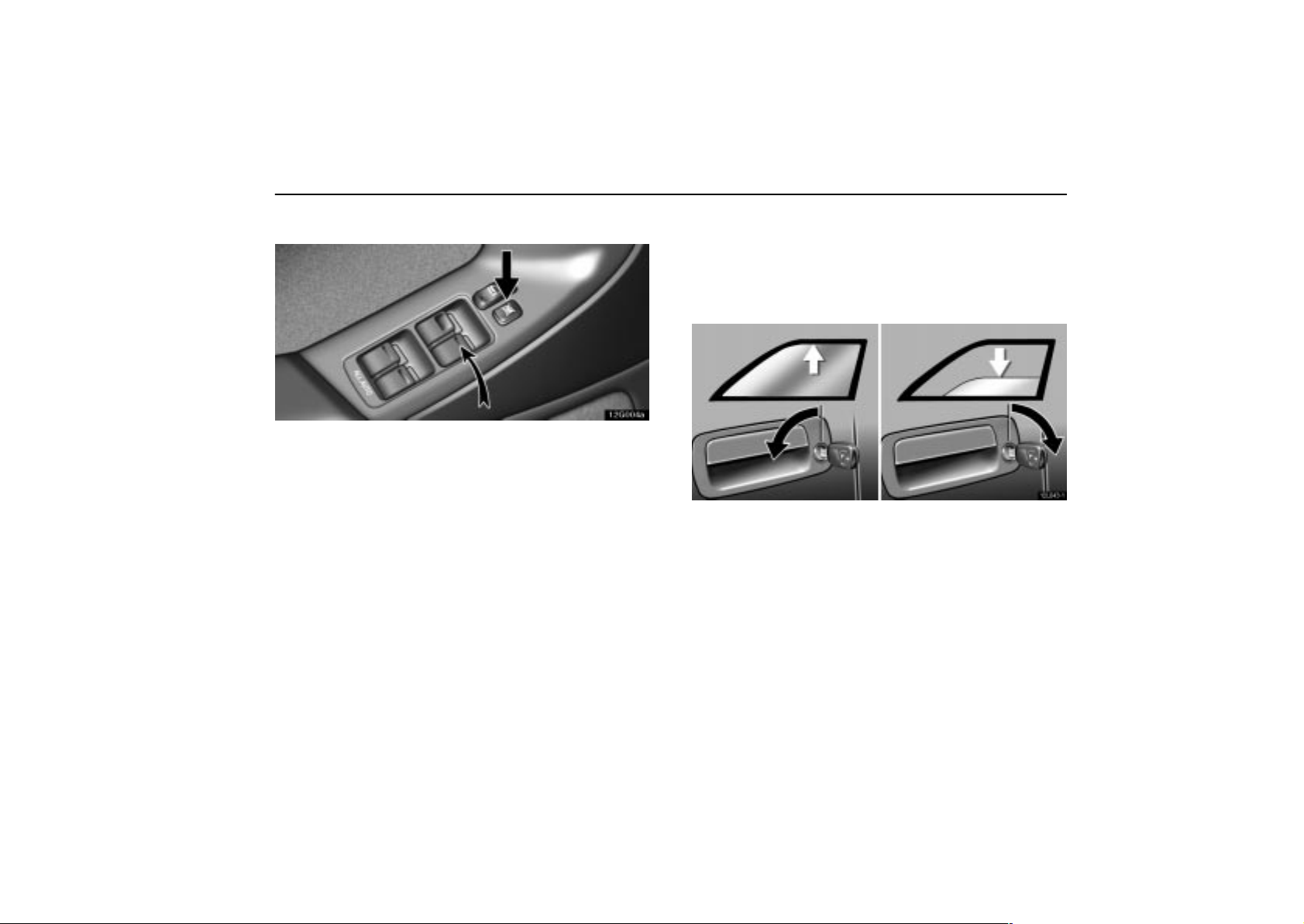
Operating the window lock switch
12G004a
Indicator light
With the window lock switch pressed in, only the driver’s
window can be raised or lowered.
The indicator lights on the switch tell you which of the switches
can be operated.
Even with the window lock switch pressed in, the windows will
be opened from outside the vehicle using an ignition key or
wireless remote control.
Operating the windows from outside the
vehicle
The windows can be operated using an ignition key.*
NOTE: *This feature can be deactivated. Ask your Lexus
dealer for details.
12L043–1
Insert the ignition key into the key hole on the driver’s
side.
To close the windows: Turn the key in the locking direction
and hold it.
After the door is locked, the windows begin to close. To stop
in the middle, return the key.
To open the windows: Turn the key in the unlocking direction
and hold it.
After the door is unlocked, the windows begin to open. To stop
in the middle, return the key.
33
Page 51

SWITCHES
This function will work even with the window lock switch
pressed in.
Jam protection function
If something gets caught between the window and window
frame during automatic raising operation, key off raising
operation or raising operation using the ignition key from the
outside, the window stops and is lowered.
If the window receives a strong impact, this function may work
even if nothing is caught.
CAUTION
To avoid serious personal injury, you must do the
following.
Before you close the power windows, always make
sure there is nobody around the power windows. You
must also make sure the heads, hands and other
parts of the bodies of all occupants are kept
completely inside the vehicle. If someone’s neck,
head or hands get caught in a closing window, it
could result in a serious injury. When anyone closes
the power windows, make sure he or she operates the
windows safely.
When small children are in the vehicle, never let them
use the power window switches without supervision.
Use the window lock switch to prevent them from
making unexpected use of the switches.
Be sure to remove the ignition key when you leave
your vehicle.
Never leave anyone (particularly a small child) alone
in your vehicle, especially with the ignition key still
inserted. Otherwise, he/she could use the power
window switches and get trapped in a window.
Unattended person ( p articularly a small child) can be
involved in a serious accident.
Never try jamming any part of your body to activate
the jam protection function intentionally.
The jam protection function may not work if
something gets caught just before the window fully
closed.
34
Page 52
SWITCHES
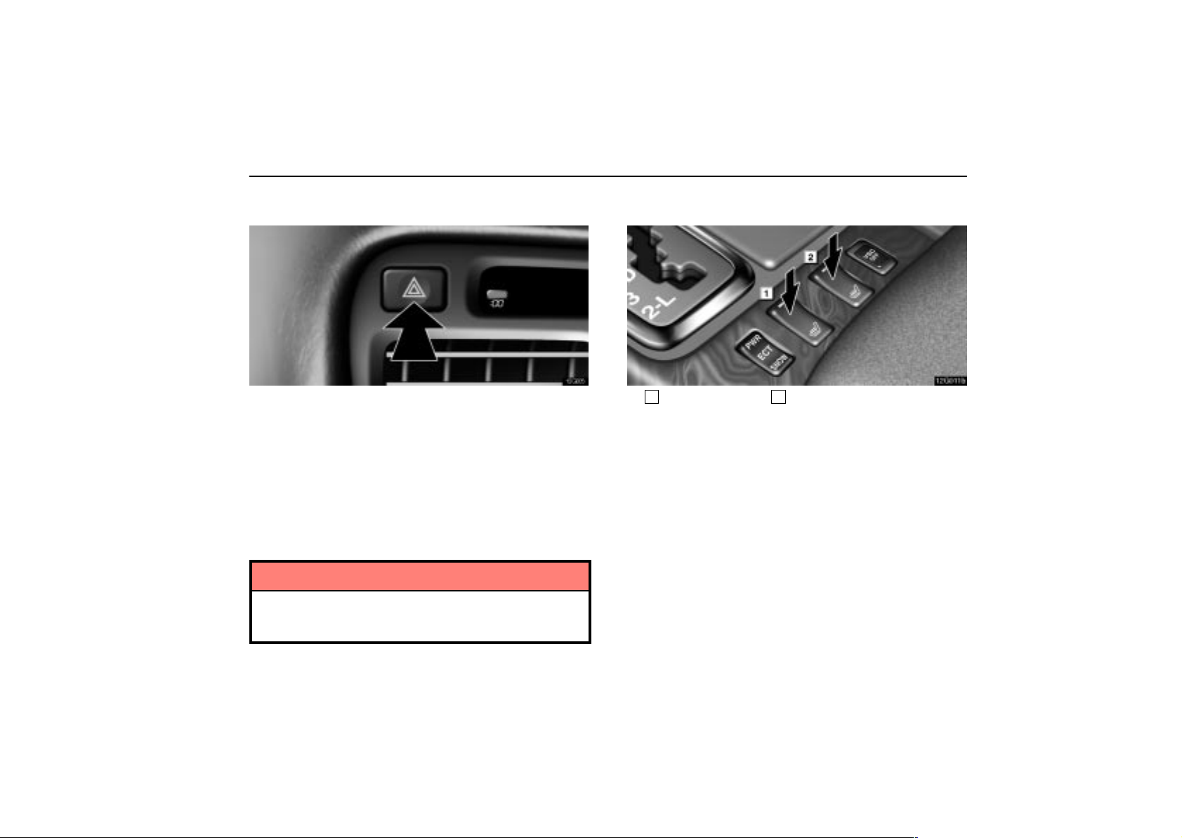
EMERGENCY FLASHER SWITCH
12G005
To turn on the emergency flashers, push the switch.
All the turn signal lights will flash. The emergency flashers will
work with the engine running or off and with or without the
ignition key.
Turn on the emergency flashers to warn other drivers if you
must stop your vehicle where it might be a traffic hazard.
Always pull your vehicle as far off the road as possible.
The turn signal light switch will not work when the emergency
flashers are in operation.
NOTICE
To prevent the battery from being discharged, do not
leave the switch on longer than necessary when the
engine is not running.
SEAT HEATER SWITCHES
12G011b
1
For driver’s seat 2For front passenger’s seat
There is a heater switch for each front seat. Push the front
of the switch to turn the heater on and push the rear side
to turn it off.
The ignition key must be in the ”ON” position.
35
Page 53
SWITCHES
CAUTION
Occupants must use caution when operating the seat
heater because they may experience minor burns even
at low temperatures. Use extra caution for;
Babies, small children, elderly persons, sick persons
or handicapped persons
Persons who have delicate skin
Persons who are exhausted
Persons who have taken alcohol or drugs which
induce sleep (sleeping drug, cold remedy, etc.).
To prevent the seat from overheating, do not use the
seat heater with a blanket, cushion, or other insulating
objects which cover the seat.
NOTICE
Do not put unevenly weighted objects on the seat and
do not stick sharp objects (needles, nails, etc.) into
the seat.
When cleaning the seats, do not use organic
substances (paint thinner, benzine, alcohol,
gasoline, etc.). They may damage the heater and seat
surface.
To prevent the battery from being discharged, turn
the switches off when the engine is not running.
36
Page 54

SECTION 1 –
INSTRUMENTS AND CONTROLS
Gauges, meters and service reminder
indicators
Fuel gauge 38. . . . . . . . . . . . . . . . . . . . . . . . . . . . . . . . . . . . . . . . . . . . . . .
Engine coolant temperature gauge 38. . . . . . . . . . . . . . . . . . . . . . . . . .
Tachometer 39. . . . . . . . . . . . . . . . . . . . . . . . . . . . . . . . . . . . . . . . . . . . . .
Odometer and trip meter 40. . . . . . . . . . . . . . . . . . . . . . . . . . . . . . . . . . .
Service reminder indicators and warning buzzers 40. . . . . . . . . . . . . .
Instrument panel light control 50. . . . . . . . . . . . . . . . . . . . . . . . . . . . . . .
3
37
Page 55
GAUGES, METERS AND SERVICE REMINDER INDICATORS
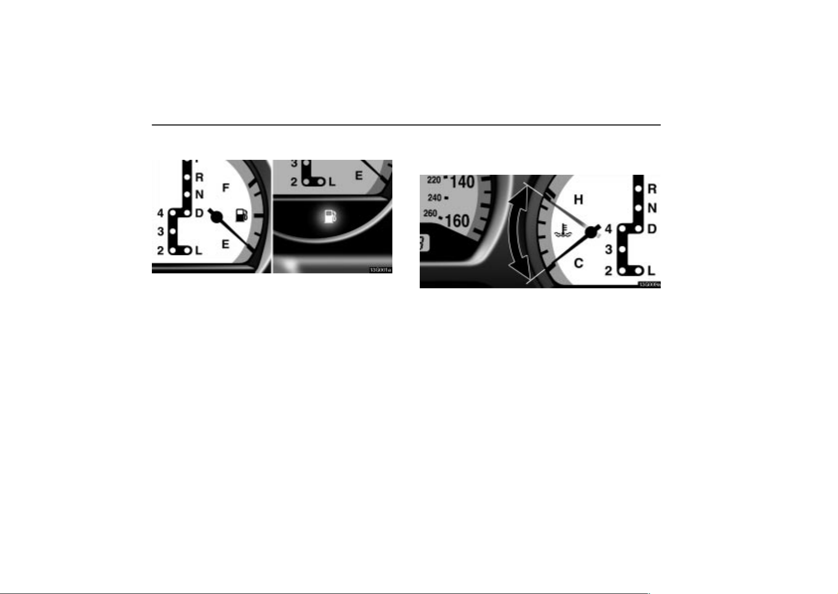
FUEL GAUGE
13G001a
The gauge indicates the approximate quantity of fuel
remaining in the tank when the ignition switch is on.
It is a good idea to keep the tank over 1/4 full.
If the fuel level approaches ”E” or the low fuel level warning light
comes on, fill the fuel tank as soon as possible.
On inclines or curves, due to the movement of fuel in the tank,
the fuel gauge needle may fluctuate or the low fuel level
warning light may come on earlier than usual.
If the fuel tank is completely empty, the malfunction indicator
lamp comes on. Fill the fuel tank immediately.
The indicator lamp goes off after driving several times. If the
indicator lamp does not go off, contact your Lexus dealer as
soon as possible.
See the inner back cover for fuel capacity and recommended
fuel selection.
ENGINE COOLANT
TEMPERATURE GAUGE
13G009a
Normal range
The gauge indicates the engine coolant temperature when
the ignition switch is on. The engine operating
temperature will vary with changes in weather and engine
load.
If the needle points to the red zone or higher, stop your vehicle
and allow the engine to cool.
Y our vehicle may overheat during severe operating conditions,
such as:
Driving up a long hill on a hot day.
Reducing speed or stopping after high speed driving.
Idling for a long period with the air conditioning on in
stop–and–go traffic.
38
Page 56
GAUGES, METERS AND SERVICE REMINDER INDICATORS
NOTICE
Do not remove the thermostat in the engine cooling
system as this may cause the engine to overheat. The
thermostat is designed to control the flow of coolant
to keep the temperature of the engine within the
specified operating range.
Do not continue driving with an overheated engine.
See ”If your vehicle overheats” on page 217.
TACHOMETER
13G006d
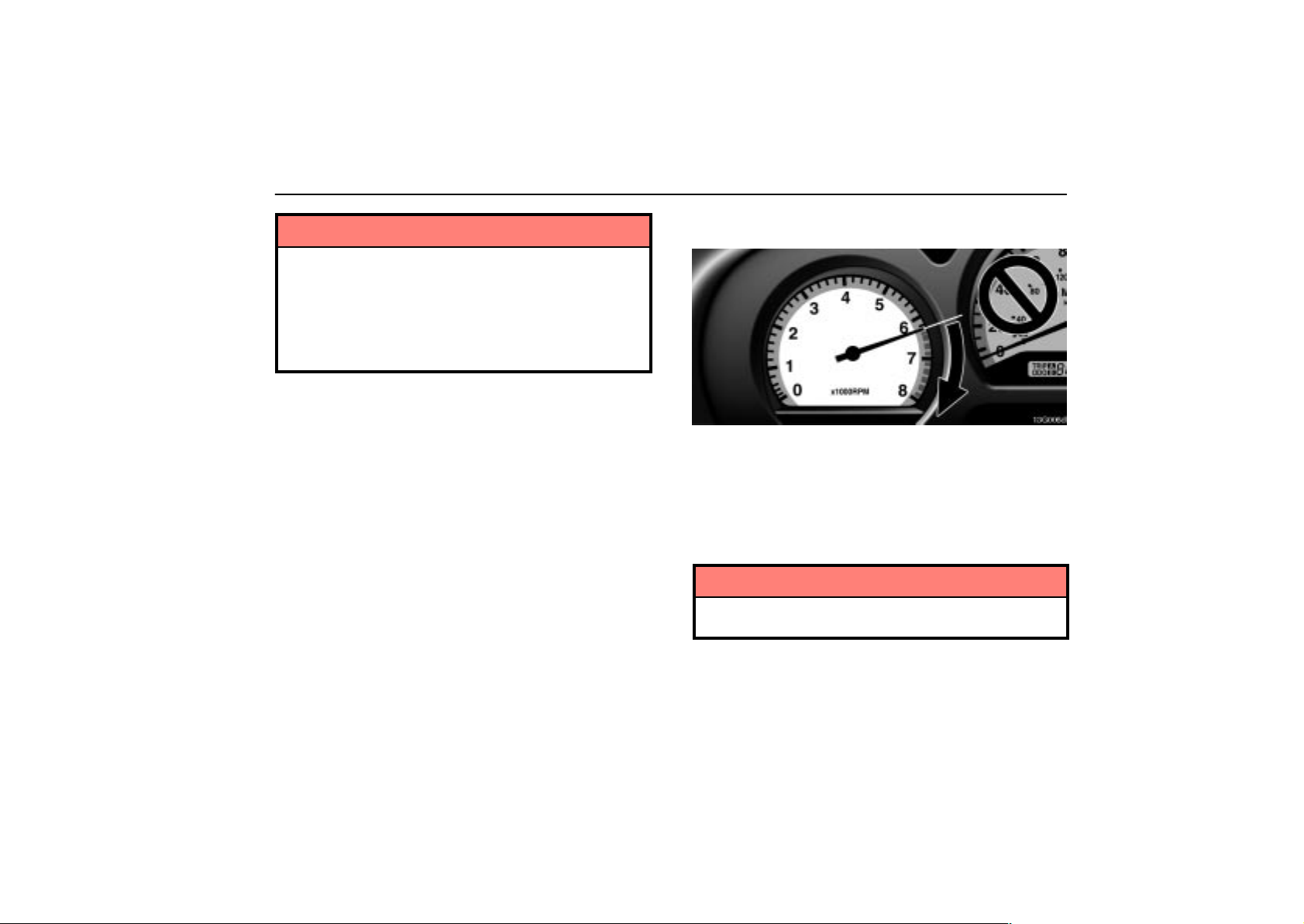
The tachometer indicates engine speed in thousands of
rpm (revolutions per minute). Use it while driving to
prevent engine over–revving.
Driving with the engine running too fast causes excessive
engine wear and poor fuel economy. Remember, in most
cases the slower the engine speed, the greater the fuel
economy.
NOTICE
Do not let the indicator needle get into the red zone. This
may cause severe engine damage.
39
Page 57
GAUGES, METERS AND SERVICE REMINDER INDICATORS
ODOMETER AND TRIP METER
13G004
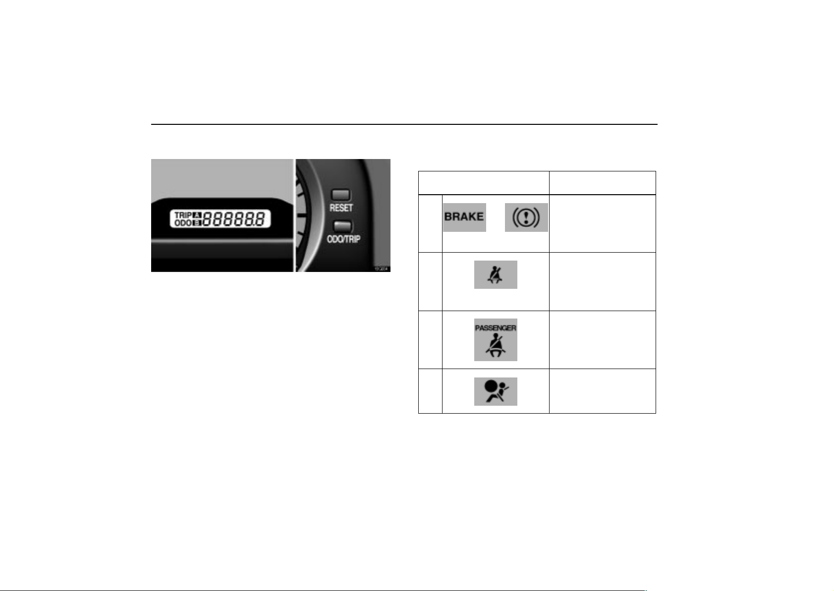
This meter displays the odometer and two trip meters. To
change the mode indication, push the ”ODO/TRIP”
button.
The odometer records the total distance the vehicle has
been driven. The twin trip meter records two different
distances independently.
For example, you can use one meter to calculate the fuel
economy and the other to measure the distance on each trip.
To change the trip meter indication from one trip to the
other, push the ”ODO/TRIP” button. To set the A trip meter
to zero, display the A meter reading, then push the
”RESET” button. The same applies for the B trip meter.
The data of trip meters will be cancelled if the electrical power
source is disconnected.
SERVICE REMINDER INDICATORS
AND WARNING BUZZERS
IF THIS INDICATOR OR
BUZZER COMES ON ...
(a)
(Indicator and buzzer)
or
(b)
(Indicator and buzzer)
(c)
(d)
DO THIS.
If parking brake is off,
stop immediately and
contact Lexus dealer.
Fasten driver’s seat
belt.
Fasten front
passenger’s seat belt.
Take vehicle to Lexus
dealer immediately.
40
Page 58
GAUGES, METERS AND SERVICE REMINDER INDICATORS
IF THIS INDICATOR OR
BUZZER COMES ON ...
(e)
(f)
(g)
(h)
(i)
or
or
DO THIS.
Stop and check.
Stop and check.
Add engine oil.
Take vehicle to Lexus
dealer.
Take vehicle to Lexus
dealer.
If brake system
warning light is also
on, stop immediately
and contact Lexus
dealer.
IF THIS INDICATOR OR
BUZZER COMES ON ...
(j)
(k)
(l)
(m)
(n)
DO THIS.
Close all doors.
Replace bulb.
Add washer fluid.
Fill up tank.
Take vehicle to Lexus
dealer.
41
Page 59
GAUGES, METERS AND SERVICE REMINDER INDICATORS
IF THIS INDICATOR OR
BUZZER COMES ON ...
(o)
(p)
and
Key reminder
buzzer
DO THIS.
Take vehicle to Lexus
dealer.
Remove key.
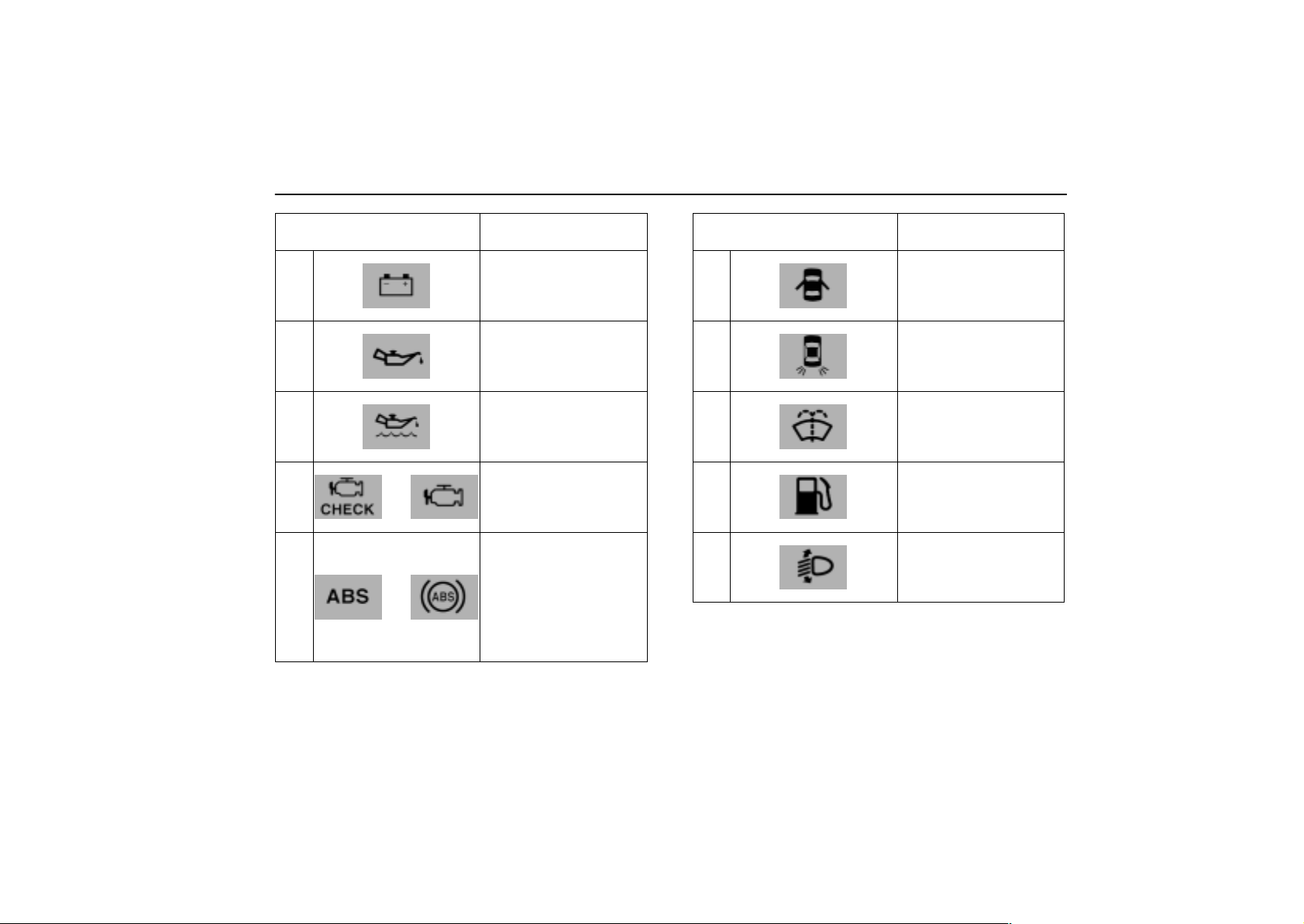
(a) Brake System Warning Light and Buzzer
This light comes on in the following cases when the ignition key
is in the “ON” position.
When the parking brake is applied ...
This light comes on for a few seconds when the ignition key is
turned to the “ON” position even after the parking brake is
released.
If you drive your vehicle without releasing the parking brake,
the buzzer sounds.
When the brake fluid level is low ...
CAUTION
It is dangerous to continue driving normally when the
brake fluid level is low.
When the hydraulic brake booster fails ...
If the hydraulic booster causes a problem resulting in poor
braking performance, the warning light comes on and buzzer
sounds continuously.
Have your vehicle checked at your Lexus dealer in the
following cases:
The light does not come on even if the parking brake is
applied when the ignition key is turned to the “ON” position.
The light does not come on even if the ignition key is turned
on with the parking brake released.
A warning light turned on briefly during operation does not
indicate a problem.
42
Page 60
GAUGES, METERS AND SERVICE REMINDER INDICATORS
CAUTION
If either of the following conditions occurs, immediately
stop your vehicle at a safe place and contact your Lexus
dealer.
The light does not turn off even after the parking
brake is released while the engine is running.
The warning buzzer comes on together with the
warning light.
In either case, this can indicate that the brakes may not
work properly and your stopping distance will become
longer. Depress the brake pedal firmly and bring the
vehicle to an immediate stop.
Any of the following conditions may occur, but do not
indicate the malfunction:
The light may stay on for about 60 seconds after the ignition
key is turned to the “ON” position. It is normal if it turns off
after a while.
Depressing the brake pedal repeatedly may turn on the
warning light and buzzer. It is normal if the light turns off and
the buzzer stops sounding after a few seconds.
You may hear a small sound in the engine compartment
after the engine is started or the brake pedal is depressed
repeatedly. This is a pump pulsating sound of the brake
system, and it is not a malfunction.
(b) Driver’s Seat Belt Reminder Light and
Buzzer
This light and buzzer remind you to buckle up the driver’s seat
belt.
Once the ignition key is turned to ”ON” or ”START”, the
reminder light flashes and buzzer sounds if the driver’s seat
belt is not fastened. Unless the driver fastens the belt, the light
stays flashing and the buzzer stops after about 4 to 8 seconds.
(c) Front Passenger’s Seat Belt Reminder
Light
This light reminds you to buckle up the front passenger’s seat
belt.
Once the ignition key is turned to ”ON” or ”START”, the
reminder light flashes if a passenger sits in the front passenger
seat and does not fasten the seat belt. Unless the front
passenger fastens the belt, the light stays flashing. However,
if a front passenger uses an additional seat cushion, the light
may not flash even when the seat belt is not buckled up.
If luggage or other load is placed on the front passenger seat,
depending on its weight and how it is placed on the seat,
built–in sensors in the seat cushion may detect the pressure,
causing the reminder light to come on.
43
Page 61
GAUGES, METERS AND SERVICE REMINDER INDICATORS
(d) SRS Warning Light
The indicator comes on when the ignition key is turned to
the ”ON” position. It goes off after about 6 seconds. This
means the SRS airbags and seat belt pretensioners are
operating properly.
The SRS warning light system monitors the airbag sensor
assembly, front airbag sensors, side and curtain shield airbag
sensors, occupant detection sensor, seat belt buckle switch,
front seat belt pretensioner assemblies, inflators, warning light,
interconnecting wiring and power sources.
If either of the following conditions occurs, this indicates a
malfunction somewhere in the parts monitored by the warning
light system. Contact your Lexus dealer as soon as possible
to service the vehicle.
When the ignition key is turned to the “ON” position, the light
does not come on, remains on or flashes.
The light comes on or starts flashing while driving.
If the light stays on, it indicates that the driver and front
passenger airbags have a problem. If the light flashes, the side
and curtain shield airbags and/or seat belt pretensioners have
a problem.
(e) Discharge Warning Light
This light warns that the battery is being discharged.
If it comes on while you are driving, stop the vehicle, turn off the
engine, and check for the cause. Look first at the engine drive
belt.
If it is loose or broken, the generator will not charge the
battery properly.
If the belt is O.K., there is a problem somewhere in the
charging system.
The engine ignition will continue to operate, however, until the
battery is discharged. Turn off the air conditioning, blower,
radio, etc., and drive directly to the nearest Lexus dealer or
repair shop.
NOTICE
Do not continue driving if the engine drive belt is broken
or loose.
44
Page 62

GAUGES, METERS AND SERVICE REMINDER INDICATORS
(f) Low Engine Oil Pressure Warning Light
This light warns that the engine oil pressure is too low.
If it flickers or stays on while you are driving, pull off the road
to a safe place and stop the engine immediately. Call a Lexus
dealer or qualified repair shop for assistance.
The light may occasionally flicker when the engine is idling or
it may come on briefly after a hard stop. There is no cause for
concern if it then goes out when the engine is accelerated
slightly.
The light may come on when the oil level is extremely low. It
is not designed to indicate low oil level, and the oil level must
be checked using the oil level dipstick.
NOTICE
Do not drive the vehicle with the warning light on – even
for one block. It may ruin the engine.
(g) Low Engine Oil Level Warning Light
This light warns that the engine oil level is too low. Add oil as
soon as possible. (For instructions, see ”Checking the engine
oil level” on page 260.)
While driving on steep inclines or rough roads which causes
the vehicle to substantially sway or on curves, this light may
come on due to the movement of engine oil in the engine.
In normal conditions, due to engine oil consumption, this light
may come on earlier than the specified service interval of the
scheduled maintenance. This is because the engine oil is
consumed to the low level within the scheduled maintenance
interval and does not indicate a problem. (For detailed
information, see “Facts about engine oil consumption” on page
258.)
NOTICE
Continued engine operation with low engine oil will
damage the engine.
45
Page 63

GAUGES, METERS AND SERVICE REMINDER INDICATORS
(h) Malfunction Indicator Lamp
This lamp comes on when the ignition key is turned to the
“ON” position and goes off after the engine starts. This
means that the warning light system is operating properly.
If the lamp remains on, or the lamp comes on while
driving, first check the followings:
Empty fuel tank
If the fuel tank is empty, refuel immediately.
Loose fuel tank cap
If the fuel tank cap is loose, securely tighten it.
These cases are temporary malfunctions. The malfunction
indicator lamp will go off after taking several driving trips.
If the lamp will not go off even after several trips, contact your
Lexus dealer as soon as possible.
If the fuel tank is not empty or the fuel tank cap is not
loose...
There is a problem somewhere in the engine, emission
control system, electronic throttle control system, automatic
transmission electrical system or warning light system itself.
Contact your Lexus dealer as soon as possible to service the
vehicle.
GS430
If this lamp comes on and the engine speed does not increase
with the accelerator pedal depressed, there may be a problem
somewhere in your electronic throttle control system.
At this time, vibration may occur. However, if you depress the
accelerator pedal more firmly and slowly, you can drive your
vehicle at low speeds. Have your Lexus checked by your
Lexus dealer as soon as possible.
Even if the a b n o r m a lity of the electronic throttle control system
is corrected during low speed driving, the system may not be
recovered until the engine is stopped and the ignition key is
turned to “ACC” or “LOCK” position.
GS300
If this lamp comes on and the engine speed does not increase
with the accelerator pedal depressed down to about the middle
position, there may be a problem somewhere in your electronic
throttle control system.
At this time, if you depress the accelerator pedal more firmly
and slowly, you can drive your vehicle at low speeds. Have
your Lexus checked by your Lexus dealer as soon as possible.
Even if the a b n o r m a lity of the electronic throttle control system
is corrected during low speed driving, the system may not be
recovered until the engine is stopped and the ignition key is
turned to “ACC” or “LOCK” position.
46
Page 64

GAUGES, METERS AND SERVICE REMINDER INDICATORS
Emissions inspection and maintenance (I/M) programs
Your vehicle may not pass a state emission inspection if the
malfunction indicator lamp remains on. Contact your Lexus
dealer to check your vehicle’s emission control system and
OBD (On–Board Diagnostics) system before taking your
vehicle for the inspection.
For details, see “Emissions inspection and maintenance (I/M)
programs” on page 239.
(i) ”ABS” Warning Light
The light comes on when the ignition key is turned to the “ON”
position. If the anti–lock brake system and the brake assist
system work properly, the light turns off after a few seconds.
Thereafter, if either of the systems malfunctions, the light
comes on again.
When the “ABS” warning light is on (and the brake system
warning light is off), the anti–lock brake system, the brake
assist system, the traction control system and/or the vehicle
stability control system do/does not operate, but the brake
system still operates conventionally.
When the “ABS” warning light is on (and the brake system
warning light is off), the anti–lock brake system does not
operate so that the wheels could lock up during a sudden
braking or braking on slippery road surfaces.
If either of the following conditions occurs, this indicates
a malfunction somewhere in the parts monitored by the
warning light system. Contact your Lexus dealer as soon
as possible to service the vehicle.
The light does not come on when the ignition key is turned
to the “ON” position, or remains on.
The light comes on while you are driving.
47
Page 65

GAUGES, METERS AND SERVICE REMINDER INDICATORS
A warning light turning on briefly during operation does not
indicate a problem.
Either of the following conditions may occur, but do not
indicate the malfunction:
The light may stay on for about 60 seconds after the ignition
key is turned to the “ON” position. It is normal if it turns off
after a while.
Depressing the brake pedal repeatedly may turn on the
light. It is normal if it turns off after a few seconds.
(j) Open Door Warning Light
This light remains on until all the doors are completely closed.
(k) Rear Light Failure Warning Light
If this light comes on when the headlight switch is turned on (at
the first or second clickstop), it indicates that one or more of the
tail lights are burned out.
If it comes on when the brake pedal is depressed, one or more
stop lights are burned out.
Have defective bulbs replaced as soon as possible.
(l) Low Washer Fluid Warning Light
This light comes on when the fluid level in the tank becomes
very low. Fill the tank as soon as possible.
(m) Low Fuel Level Warning Light
This light comes on when the fuel level in the tank becomes
very low. Fill the tank as soon as possible.
On inclines or curves, due to the movement of fuel in the tank,
the low fuel level warning light may come on earlier than usual.
(n) Automatic Headlight Leveling System
Warning Light
This light warns that there is a problem somewhere in the
automatic headlight leveling system.
If it comes on, have your vehicle checked by your Lexus dealer.
48
Page 66
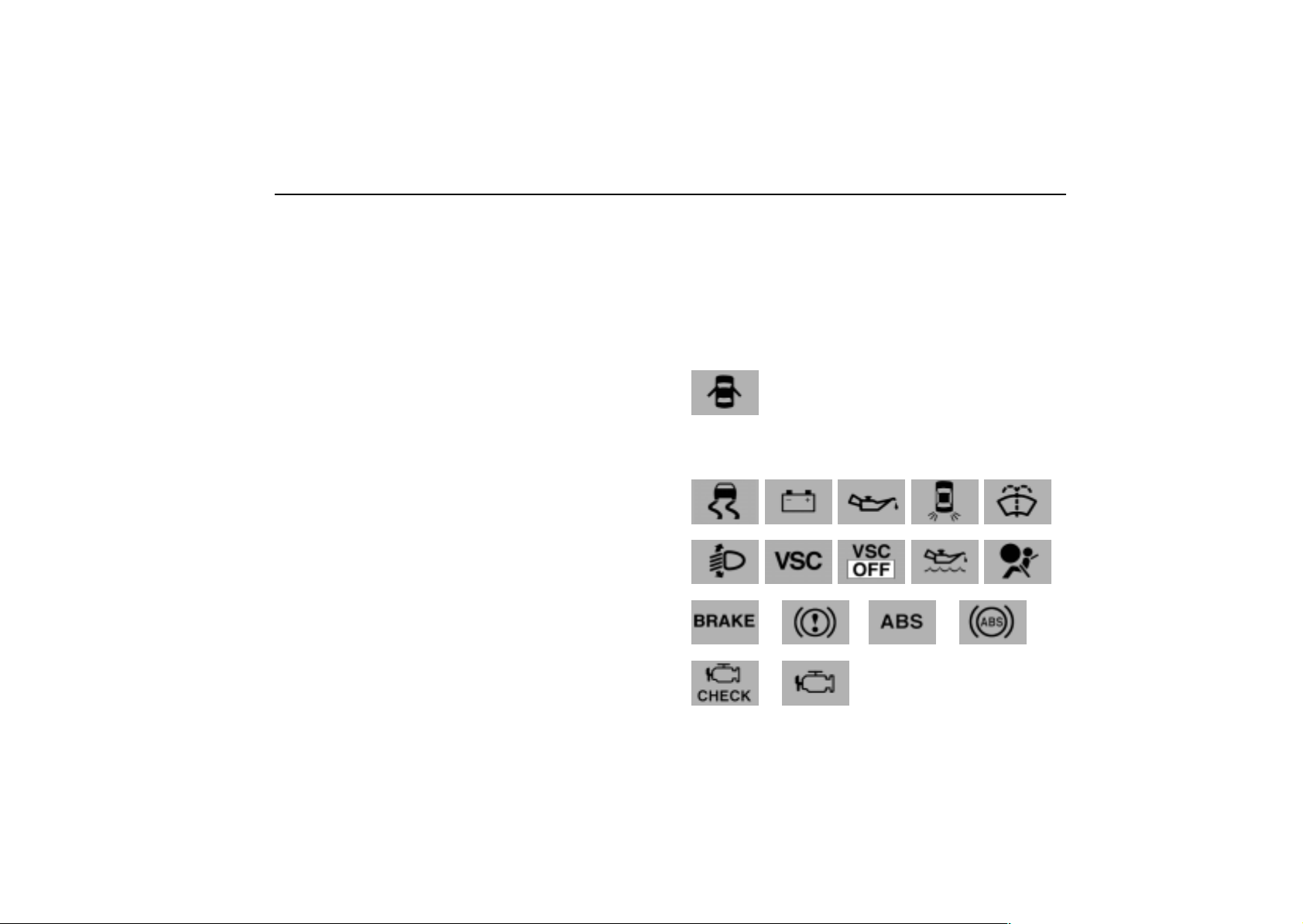
GAUGES, METERS AND SERVICE REMINDER INDICATORS
(o) Vehicle Stability Control System Warning
Lights
These lights warn that there is a problem somewhere in the
vehicle stability control system or traction control system.
If the ”VSC” warning light and ”VSC OFF” indicator light come
on, have your vehicle checked by Lexus dealer as soon as
possible.
The lights will come on when the ignition key is turned to ”ON”,
and will go off after about a few seconds.
The lights may stay on for 60 seconds after the ignition key is
turned to the “ON” position. It is normal if they go out after a
while.
Depressing the brake pedal repeatedly may turn on the lights.
It is normal if they go out after a few seconds.
If the ”VSC” warning light and ”VSC OFF” indicator light come
on, the vehicle stability control system does not activate,
however, it is no problem to continue your driving.
(p) Key Reminder Buzzer
This buzzer reminds you to remove the key when you open the
driver’s door with the ignition key in the ”ACC” or ”LOCK”
position.
How to check all the service reminder
indicators
(except the low fuel level warning light):
1. Apply the parking brake.
2. Open the door.
The following service reminder indicator should come on. It
goes off when you close the door completely.
3. Turn the ignition key to ”ON”.
The following service reminder indicators should come on.
or
or
or
49
Page 67
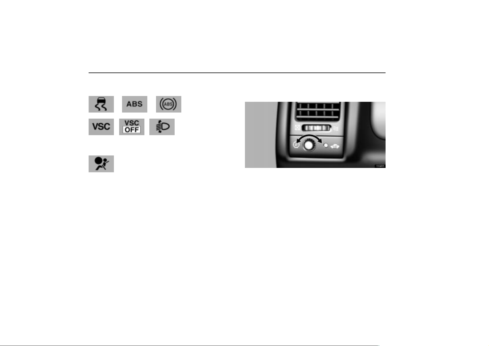
GAUGES, METERS AND SERVICE REMINDER INDICATORS
The following service reminder indicators go off after a few
seconds.
or
The following service reminder indicator goes off after about 6
seconds.
The lights other than the slip indicator light may stay on for
about 60 seconds after the ignition key is turned to the “ON”
position. It is normal if they go out after a while.
If any service reminder indicator or warning buzzer does not
function as described above, have it checked by your Lexus
dealer as soon as possible.
INSTRUMENT PANEL LIGHT
CONTROL
13G005
The brightness of the instrument panel lights is
automatically adjusted depending on the brightness of
your surroundings. T o adjust the brightness as you like,
turn the knob. However , if the brightness is automatically
adjusted at the maximum, turning the knob cannot change
the brightness.
When the headlight switch is in the first or second click stop,
you can also adjust the brightness of the displays on the audio
and air conditioning systems using this knob.
50
Page 68

SECTION 1 –
INSTRUMENTS AND CONTROLS
Interior equipment
Vanity mirrors 52. . . . . . . . . . . . . . . . . . . . . . . . . . . . . . . . . . . . . . . . . . . .
Interior lights 53. . . . . . . . . . . . . . . . . . . . . . . . . . . . . . . . . . . . . . . . . . . . .
Personal lights 53. . . . . . . . . . . . . . . . . . . . . . . . . . . . . . . . . . . . . . . . . . .
Ignition switch light 54. . . . . . . . . . . . . . . . . . . . . . . . . . . . . . . . . . . . . . . .
Clock 54. . . . . . . . . . . . . . . . . . . . . . . . . . . . . . . . . . . . . . . . . . . . . . . . . . .
Cigarette lighter and ashtray 55. . . . . . . . . . . . . . . . . . . . . . . . . . . . . . . .
Power outlet 56. . . . . . . . . . . . . . . . . . . . . . . . . . . . . . . . . . . . . . . . . . . . .
Rear console box 57. . . . . . . . . . . . . . . . . . . . . . . . . . . . . . . . . . . . . . . . .
Glove box 57. . . . . . . . . . . . . . . . . . . . . . . . . . . . . . . . . . . . . . . . . . . . . . . .
Garage door opener 58. . . . . . . . . . . . . . . . . . . . . . . . . . . . . . . . . . . . . . .
Cup holders 61. . . . . . . . . . . . . . . . . . . . . . . . . . . . . . . . . . . . . . . . . . . . . .
Coin box 62. . . . . . . . . . . . . . . . . . . . . . . . . . . . . . . . . . . . . . . . . . . . . . . . .
Tie–down hooks 62. . . . . . . . . . . . . . . . . . . . . . . . . . . . . . . . . . . . . . . . . .
Floor mat 63. . . . . . . . . . . . . . . . . . . . . . . . . . . . . . . . . . . . . . . . . . . . . . . .
First–aid kit holder 64. . . . . . . . . . . . . . . . . . . . . . . . . . . . . . . . . . . . . . . .
Luggage stowage precautions 64. . . . . . . . . . . . . . . . . . . . . . . . . . . . . .
4
51
Page 69
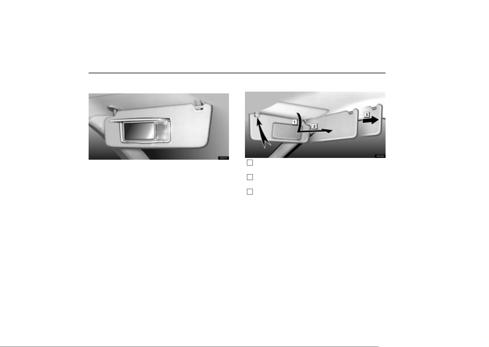
INTERIOR EQUIPMENT
VANITY MIRRORS
14G001
To use the vanity mirrors, swing the sun visor down and
open the cover.
The vanity light comes on when you open the cover.
Sun visors
14G002
1
To block out glare from the front , swing the sun visor
down.
2
To block out glare from the side, remove the sun visor
from the hook and swing it to the side.
3
To block out glare coming obliquely from behind you,
slide the visor backwards.
At this position, the vanity light does not come on.
52
Page 70
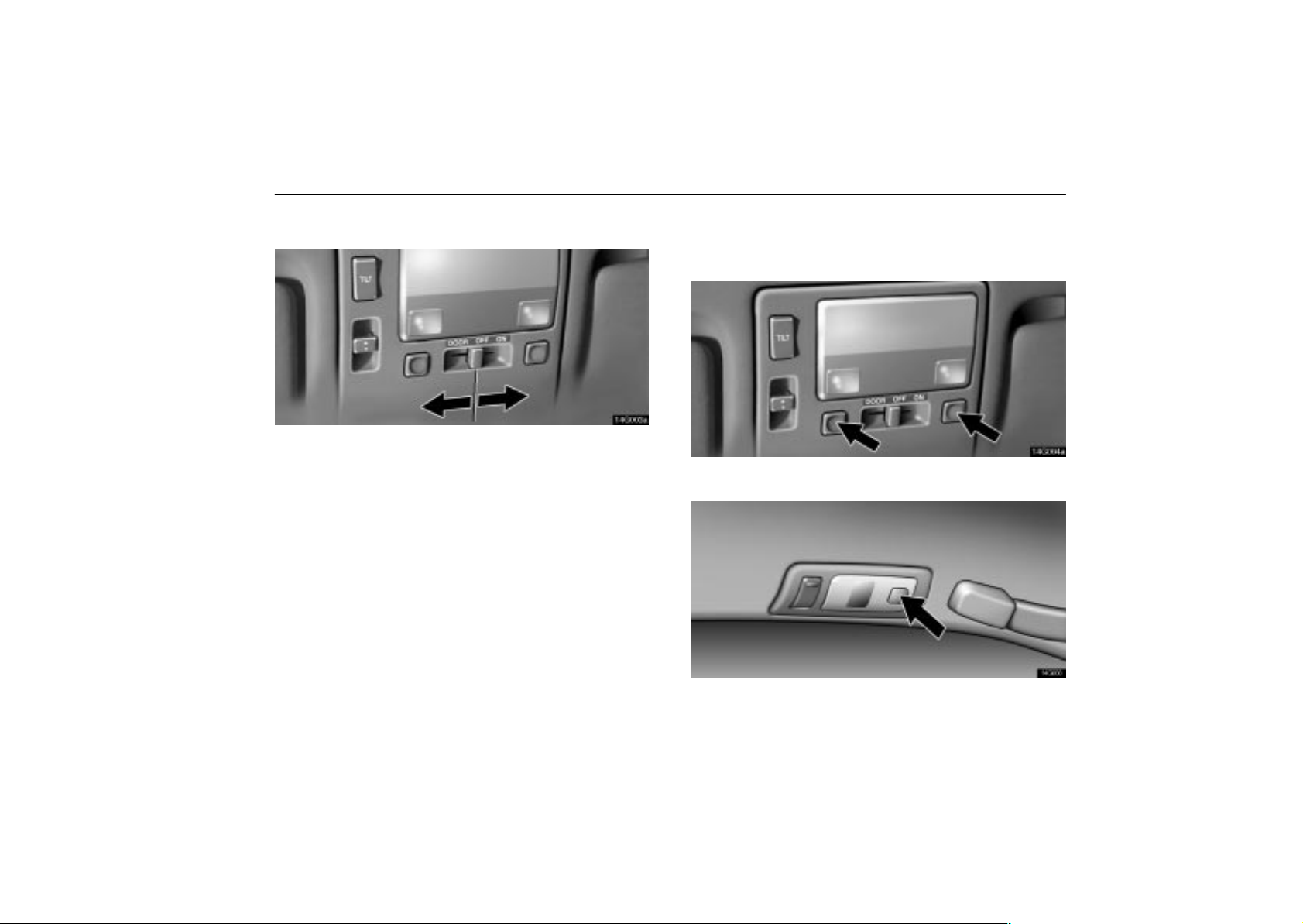
INTERIOR EQUIPMENT
INTERIOR LIGHTS
14G003a
To turn on the interior light, slide the switch.
With the switch in the ”DOOR” position, the light comes on
when any door is opened. After all the doors are closed, the
light remains on for about 15 seconds and then goes out.
However, in the following cases, the light goes out
immediately:
1. All the doors are closed when the ignition key is in ”ACC” or
”ON” position.
2. The ignition key is turned to ”ACC” or ”ON” when the light
is still on.
3. All the doors are locked when the light is still on.
4. One door is closed with the lock button pushed in while the
other doors are locked.
PERSONAL LIGHTS
Front
14G004a
Rear
14G006
To turn on the personal light, push the switch. To turn it
off, push the switch again.
53
Page 71
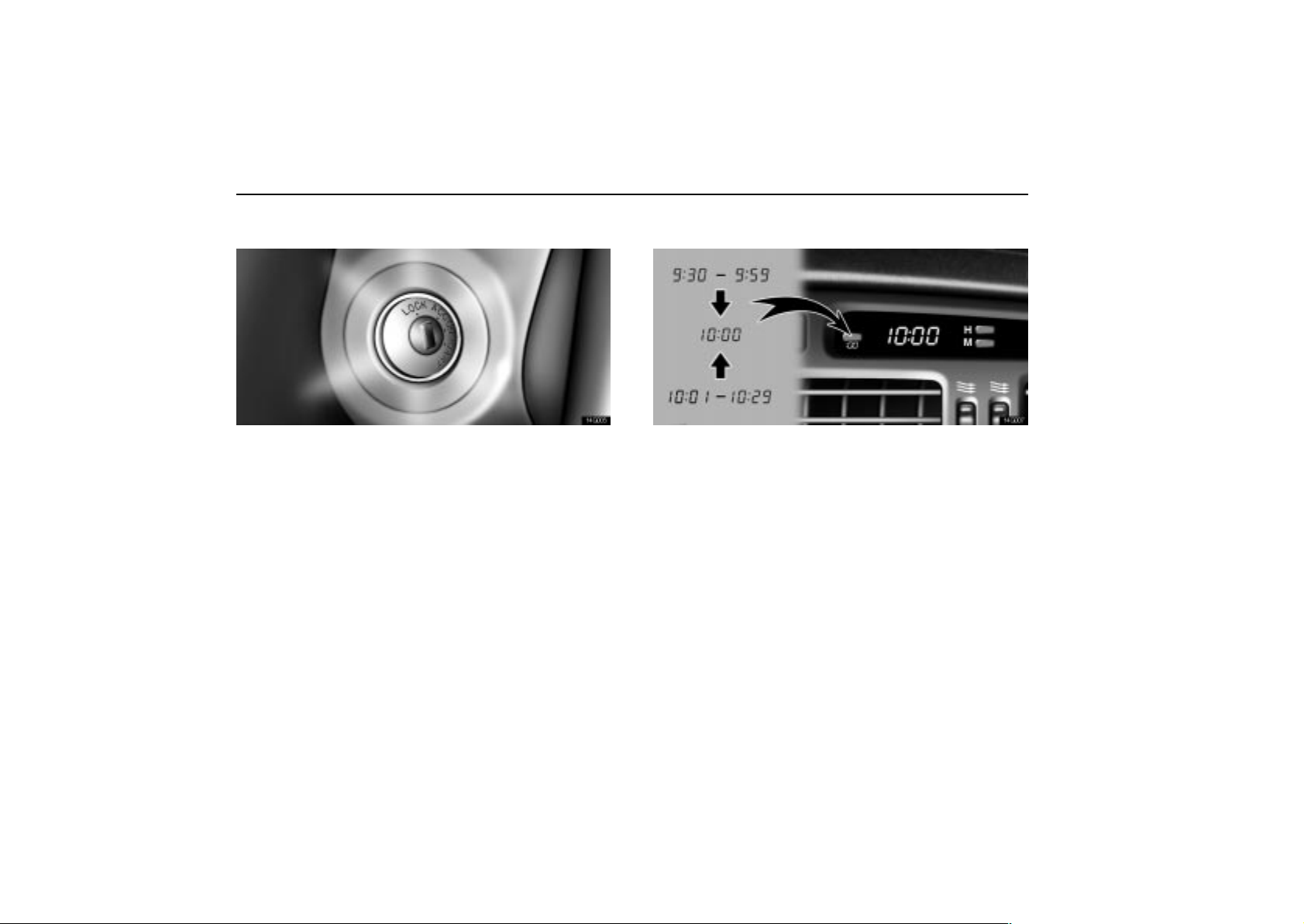
INTERIOR EQUIPMENT
IGNITION SWITCH LIGHT
14G005
For easy access to the ignition switch, the ignition switch
light comes on when any of the doors are opened.
The light remains on for about 15 seconds and goes out after
all the doors are closed. However, the light goes out
immediately when all the doors are locked or the ignition key
is in the ”ACC” or ”ON” position.
CLOCK
14G007
The digital clock indicates the time with the ignition key at
the ”ACC” or ”ON” position. T o reset the hour, press the
”H” button. To reset the minutes, press the ”M” button.
To adjust the time to the nearest hour, press the ”:00”
button.
For example, if the ”:00” button is pressed when the time is
between 9:30 – 9:59 or between 10:01 – 10:29, the time will
change to 10:00.
With the tail lights on, the background brightness of the time
indication will be reduced.
If the electrical power source has been disconnected from the
clock, the time display will automatically be set to 1:00 (one
o’clock).
54
Page 72
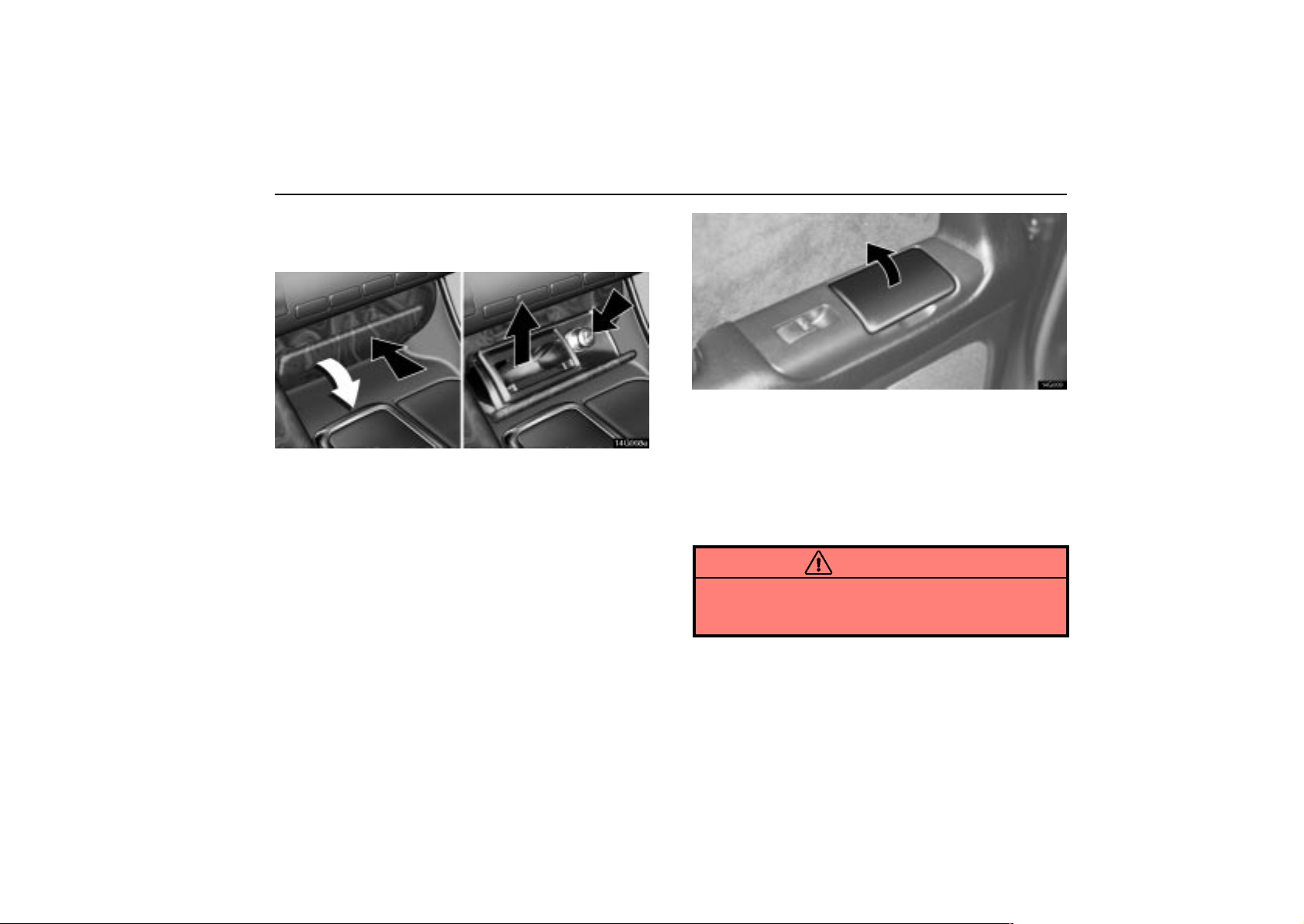
CIGARETTE LIGHTER AND
ASHTRAY
14G008e
Front cigarette lighter and ashtray
To use the cigarette lighter and ashtray, first push against
the ashtray cover. Then when the ashtray opens out,
press in the cigarette lighter. After it finishes heating up,
it automatically pops out ready for use.
Do not hold the cigarette lighter pressed in.
If the engine is not running, the ignition key must be in the
”ACC” position to use the lighter.
When finished with your cigarette, thoroughly extinguish it in
the ashtray to prevent other cigarette butts from catching fire.
After using the ashtray, push it back in completely.
To remove the ashtray, just pull it up.
Use a Lexus genuine cigarette lighter or equivalent for
replacement.
INTERIOR EQUIPMENT
14G009
Rear ashtray
To use the ashtray, pull on the lid.
When finished with your cigarette, thoroughly extinguish it in
the ashtray to prevent other cigarette butts from catching fire.
After using the ashtray, push it back in or close the lid
completely.
To remove the ashtray, just pull it up.
CAUTION
To reduce the chance of injury in case of an accident or
sudden stop while driving, always close the ashtray
completely after use.
55
Page 73
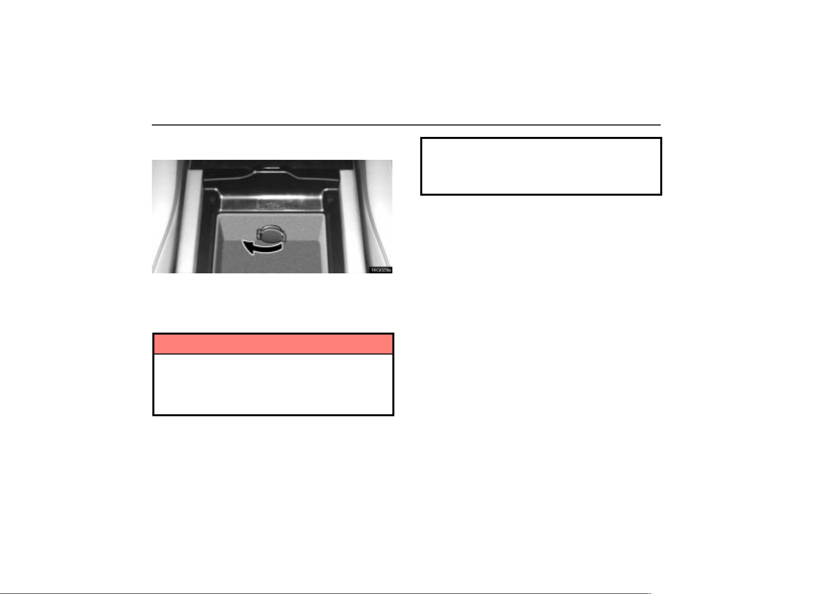
INTERIOR EQUIPMENT
POWER OUTLET
14L020a
The power outlet is designed for power supply for car
accessories.
The ignition key must be in the ”ACC” or ”ON” position for the
power outlet to be used.
NOTICE
To prevent the fuse from being blown, do not use the
electricity over the total vehicle capacity of 12V 3.5A.
To prevent the battery from being discharged, do not
use the power outlet longer than necessary when the
engine is not running.
Close the power outlet lid when the power outlet is
not in use. Inserting a foreign object other than the
appropriate plug that fits the outlet, or allowing any
liquid into the outlet may cause electrical failure or
short circuits.
56
Page 74
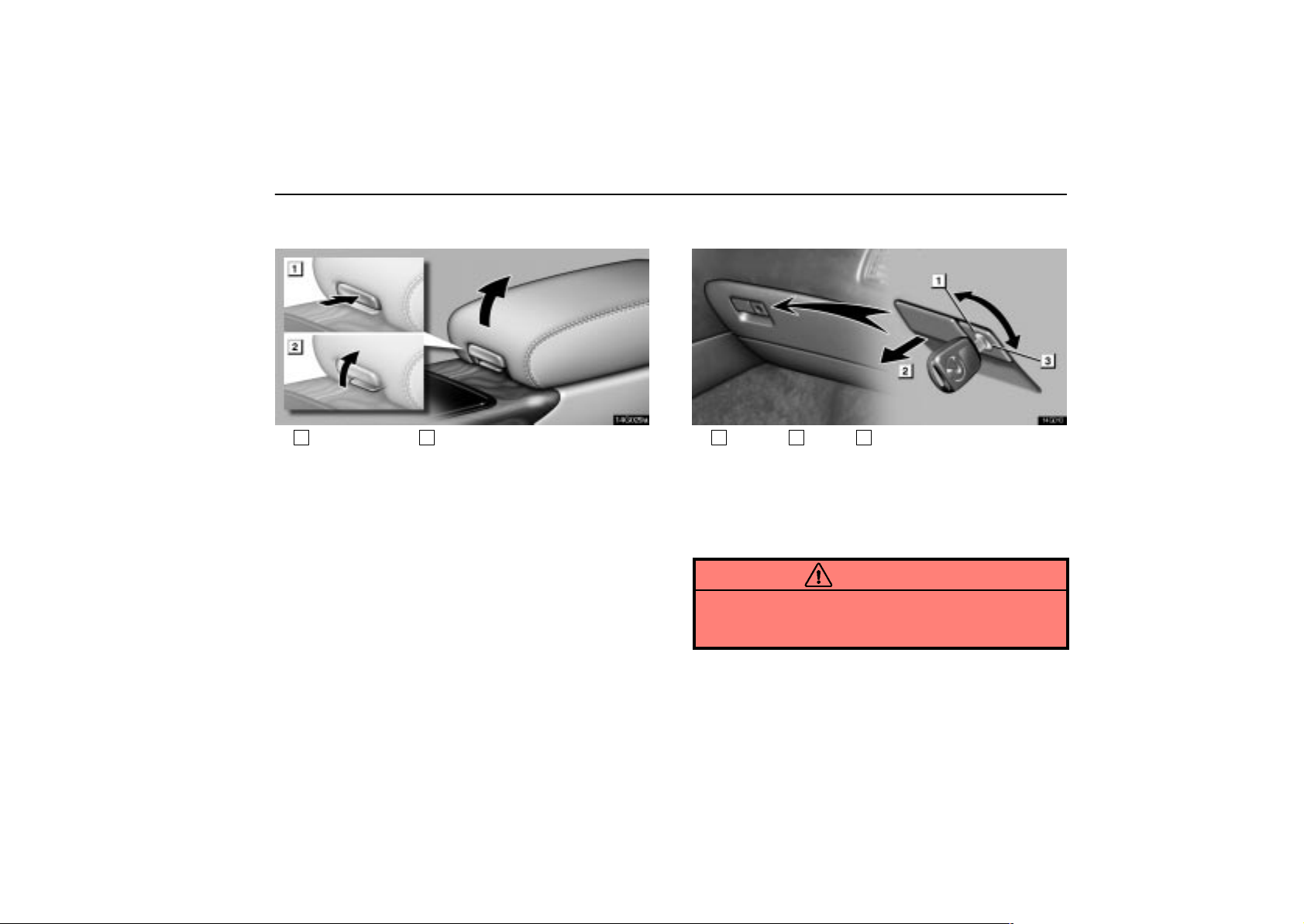
INTERIOR EQUIPMENT
REAR CONSOLE BOX
14g029a
1
For upper box 2For lower box
To use the rear console box, open as shown in the
illustration.
GLOVE BOX
14G010
1
Unlock 2Open 3Lock
To open the glove box door, pull the lever. To lock the
glove box door, insert the master key and turn it
clockwise.
With the tail lights on, the glove box light will come on when the
glove box door is open.
CAUTION
To reduce the chance of injury in case of an accident or
a sudden stop, always keep the glove box door closed
while driving.
57
Page 75
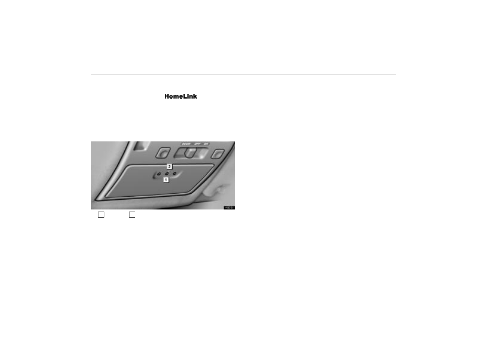
INTERIOR EQUIPMENT
GARAGE DOOR OPENER
The garage door opener (
Universal
Transceiver) is manufactured under license from
HomeLink and can be programmed to operate garage
doors, gates, entry doors, door locks, home lighting
systems, and security systems, etc.
(a) Programming the HomeLink
14G015–1
1
Buttons 2Indicator light
The HomeLink in your vehicle has 3 buttons and you can
store one program for each button.
To ensure correct programming into the HomeLink
new battery in the hand–held transmitter prior to programming.
The battery side of the hand–held transmitter must be pointed
away from the HomeLink
during the programming process.
, install a
For Canadian users, follow the procedure in “Programming an
entrance gate/Programming all devices in the Canadian
market”.
1. Decide which of 3 HomeLink
2. Place your hand–held garage transmitter 25 to 75 mm (1 to
3 in.) away from the surface of the HomeLink
buttons you want to program.
.
Keep the indicator light on the HomeLink in view while
programming.
3. Simultaneously press and hold the hand–held garage
transmitter button along with the selected HomeLink
4. When the indicator light on the HomeLink
button.
changes from a
slow to a rapid flash after 20 seconds, you can release both
buttons.
5. T est the operation of the HomeLink
by pressing the newly
programmed button. If programming a garage door opener,
check to see if the garage door opens and closes.
If the garage door does not operate, identify if your garage
transmitter is of the “Rolling Code” type. Press and hold the
programmed HomeLink
rolling code feature if the indicator light (on the HomeLink
button. The garage door has the
flashes rapidly and then remains lit after 2 seconds. If your
garage transmitter is the “Rolling Code” type, proceed to the
heading “Programming a rolling code system”.
6. Repeat steps 2 through 5 for each remaining HomeLink
button to program another device.
)
58
Page 76

INTERIOR EQUIPMENT
Programming a rolling code system
If your device is “Rolling Code” equipped, it is necessary
to follow steps 1 through 4 under the heading
“Programming the HomeLink
the steps listed below.
1. Locate the “training” button on the ceiling mounted garage
door opener motor. The exact location and color of the button
may vary by brand of garage door opener. Refer to the owner’s
guide supplied by the garage door opener manufacturer for the
location of this “training” button.
2. Press the “training” button on the ceiling mounted garage
door opener motor.
Following this step, you have 30 seconds in which to initiate
step 3 below.
3. Press and release the vehicle’s programmed HomeLink
button twice. The garage door may open. If the door does
open, the programming process is complete. If the door does
not open, press and release the button a third time. This third
press and release will complete the programming process by
opening the garage door.
The ceiling mounted garage door opener motor should now
recognize the HomeLink
garage door up/down.
4. Repeat steps 1 through 3 for each remaining HomeLink
button to program another rolling code system.
” before proceeding with
unit and be able to activate the
Programming an entrance gate /
Programming all devices in the Canadian
market
1. Decide which of the 3 HomeLink buttons you want to
program.
2. Place your hand–held gate/device transmitter 25 to 75 mm
(1 to 3 in.) away from the surface of the HomeLink
Keep the indicator light on the HomeLink in view while
programming.
3. Press and hold the selected HomeLink
4. Continuously press and release (cycle) the hand–held
gate/device transmitter button every two seconds until step 5
is complete.
5. When the indicator light on the HomeLink changes from a
slow to a rapid flash after 20 seconds, you can release both
buttons.
6. T est the operation of the HomeLink
by pressing the newly
programmed button. Check to see if the gate/device operates
correctly.
7. Repeat steps 1 through 6 for each remaining HomeLink
button to program another device.
Programming other devices
To program other devices such as home security systems,
home door locks or lighting, contact your authorized Lexus
dealer for assistance.
button.
.
59
Page 77
INTERIOR EQUIPMENT
Reprogramming a button
Individual HomeLink
reprogram a single button, follow the procedure “Programming
the HomeLink
(b) Operating the HomeLink
buttons cannot be erased, however, t o
”.
To operate the HomeLink, press the appropriate HomeLink
button to activate the programmed device. The HomeLink
indicator light should come on. The HomeLink continues to
send the signal for up to 20 seconds as long as the button is
pressed.
(c) Erasing the entire HomeLink memory
(all three programs)
To erase all previously programmed codes at one time, press
and hold down the 2 outside buttons for 20 seconds until the
indicator light flashes.
If you sell your vehicle, be sure to erase the programs stored
in the HomeLink
memory.
CAUTION
When programming the HomeLink Universal
Transceiver, you may be operating a garage door or
other device. Make sure people and objects are out
of the way of the garage door or other device to
prevent potential harm or damage.
Do not use this HomeLink Universal Transceiver
with any garage door opener that lacks the safety
stop and reverse feature as required by federal safety
standards. (This includes any garage door opener
model manufactured before April 1, 1982.) A garage
door opener which cannot detect an object
(signaling the door to stop and reverse), does not
meet current federal safety standards. Using a
garage door opener without these features increases
risk of serious injury or death.
FCC ID: CB2V94800
CANADA: 1763 102 264
This device complies with FCC Rules part 15.
Operation is subject to the following two conditions:
(1) This device may not cause harmful interference,
and (2) this device must accept any interference that
may be received, including interference that may
cause undesired operation. WARNING: This
transmitter has been tested and complies with
FCC and DOC/MDC rules. Changes or
modifications not expressly approved by the party
responsible for compliance could void the user’s
authority to operate the device.
60
Page 78
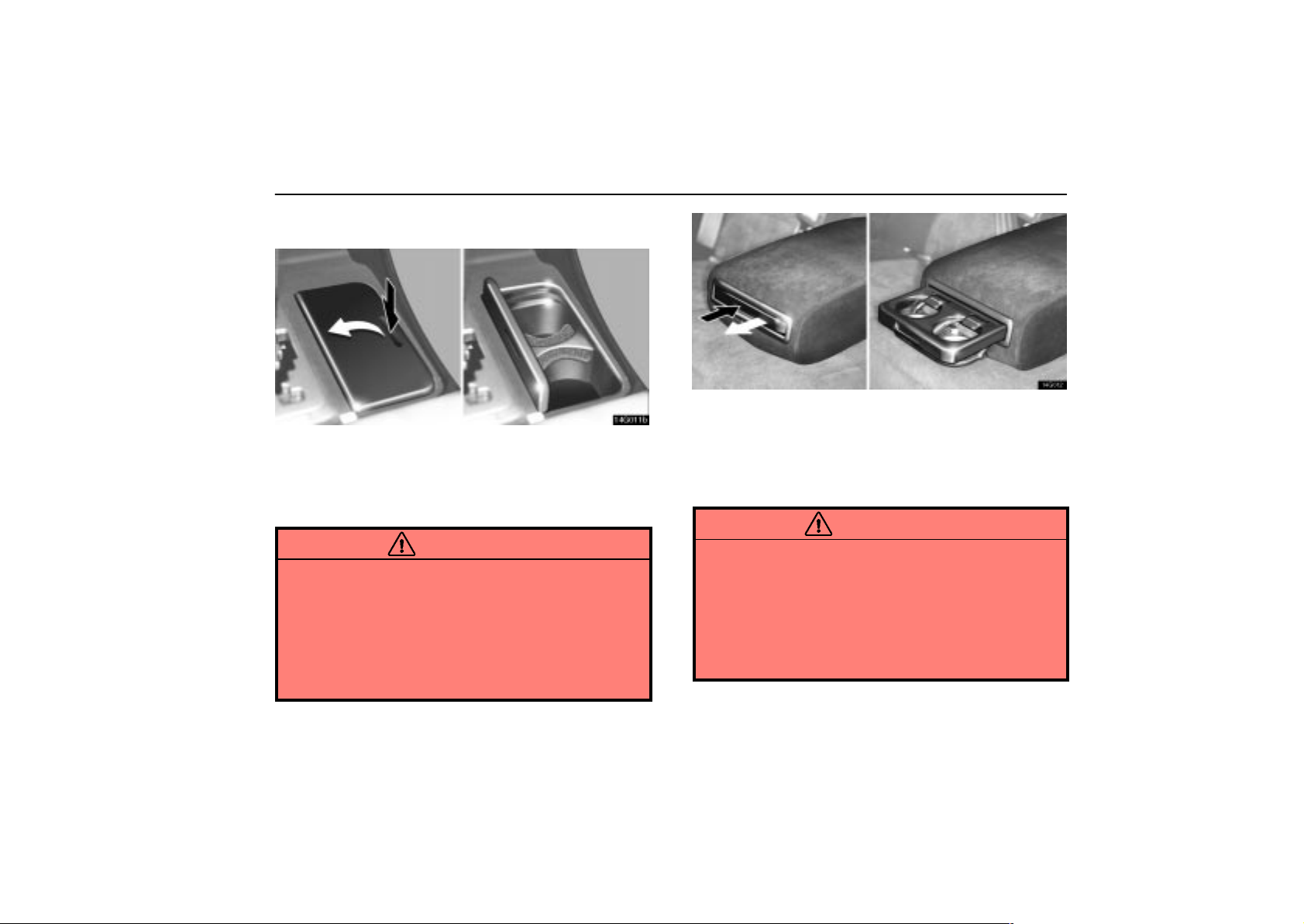
CUP HOLDERS
14G011b
Front
To use the cup holder, push the cup holder lid.
You can use it as an accessory box by removing the holder
inside.
CAUTION
Do not place anything else other than cups or
drink–cans in the cup holder, as such items may be
thrown about in the compartment and possibly injure
people in the vehicle during sudden braking or in an
accident.
To reduce the chance of injury in case of an accident
or sudden stop while driving, keep the cup holder
closed when not in use.
INTERIOR EQUIPMENT
14G012
Rear
To use the cup holder, push the cup holder portion of the
center armrest in the rear seat.
The cup holder is designed for holding cups or drink–cans
securely.
CAUTION
Do not place anything else other than cups or
drink–cans in the cup holder, as such items may be
thrown about in the compartment and possibly injure
people in the vehicle during sudden braking or in an
accident.
To reduce the chance of injury in case of an accident
or sudden stop while driving, keep the cup holder
closed when not in use.
61
Page 79
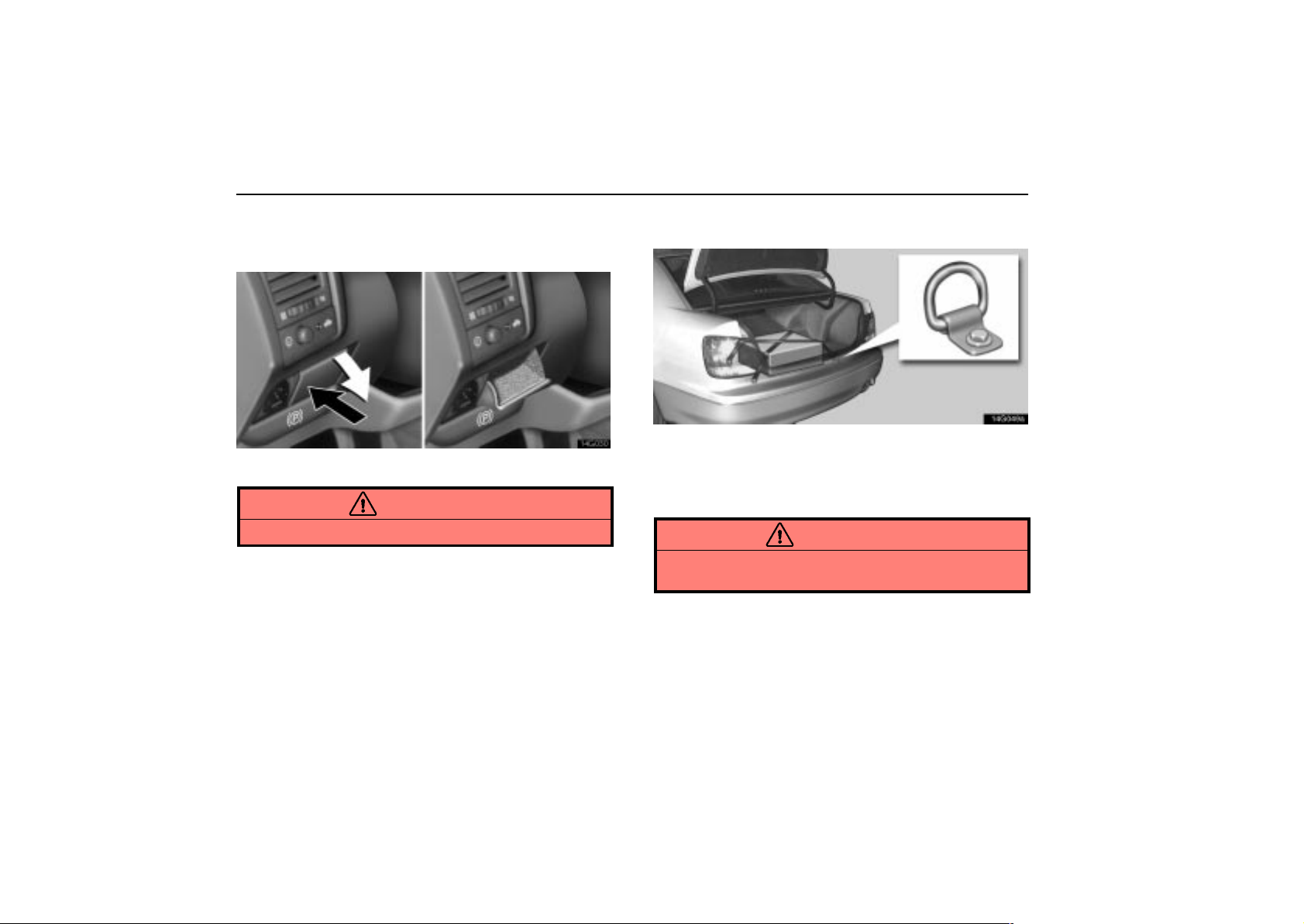
INTERIOR EQUIPMENT
COIN BOX
(U.S.A.ONLY)
14g030
To use the coin box, push against the coin box cover.
CAUTION
Keep the coin box closed when not in use.
TIE–DOWN HOOKS
14G049a
To secure your luggage, use the tie–down hooks as
shown above.
See “Luggage stowage precautions” on page 64 for
precautions in loading luggage.
CAUTION
To avoid personal injury, keep the tie–down hooks
stored under the carpet when not in use.
62
Page 80
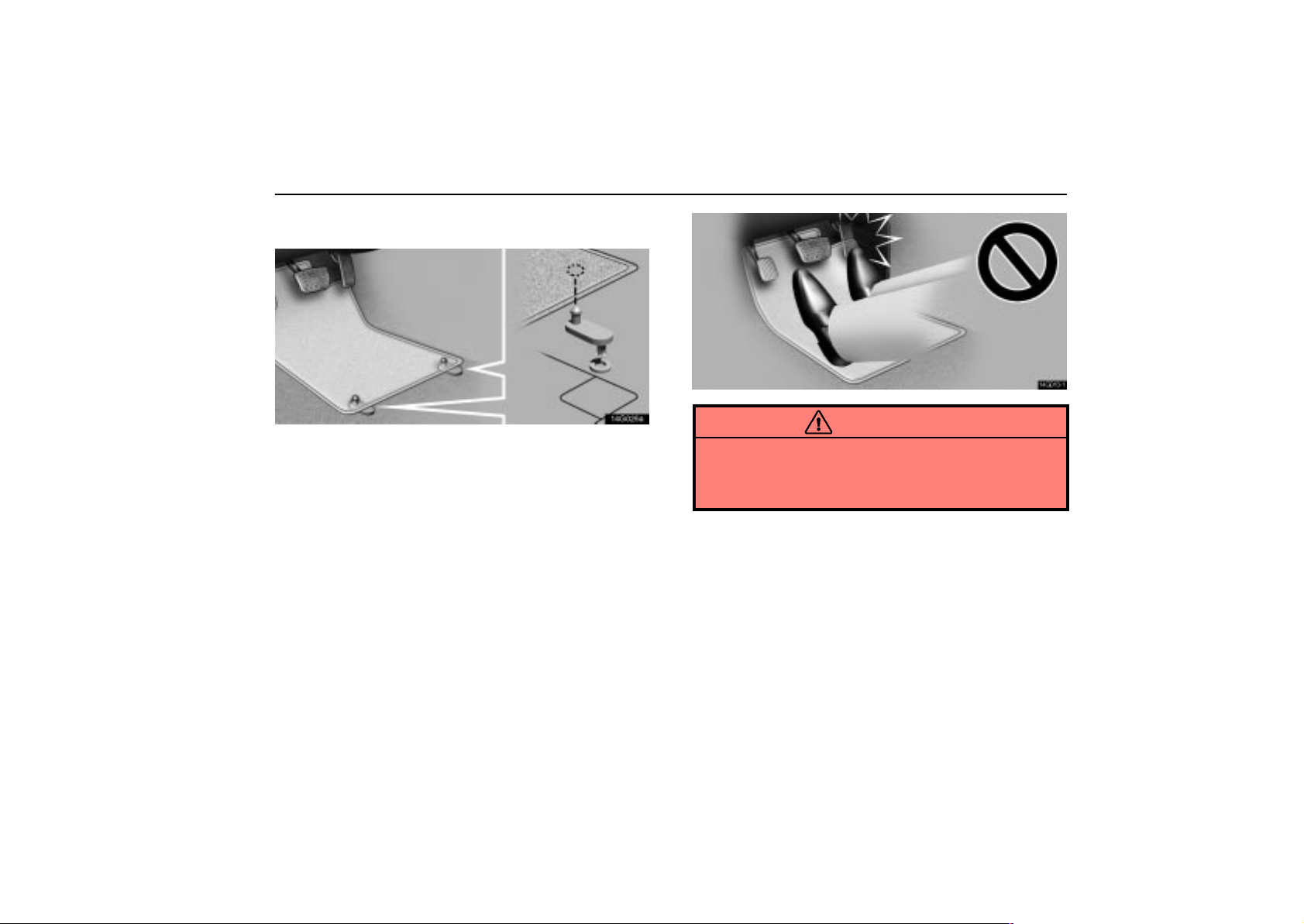
FLOOR MAT
14G025a
INTERIOR EQUIPMENT
14G013–1
Use a floor mat of the correct size.
If the floor carpet and floor mat have 2 holes, then they are
designed for use with locking clips. Fix the floor mat with
locking clips into the holes in the floor carpet.
CAUTION
Make sure the floor mat is properly placed on the floor
carpet. If the floor mat slips and interferes with the
movement of the pedals during driving, it may cause an
accident.
63
Page 81
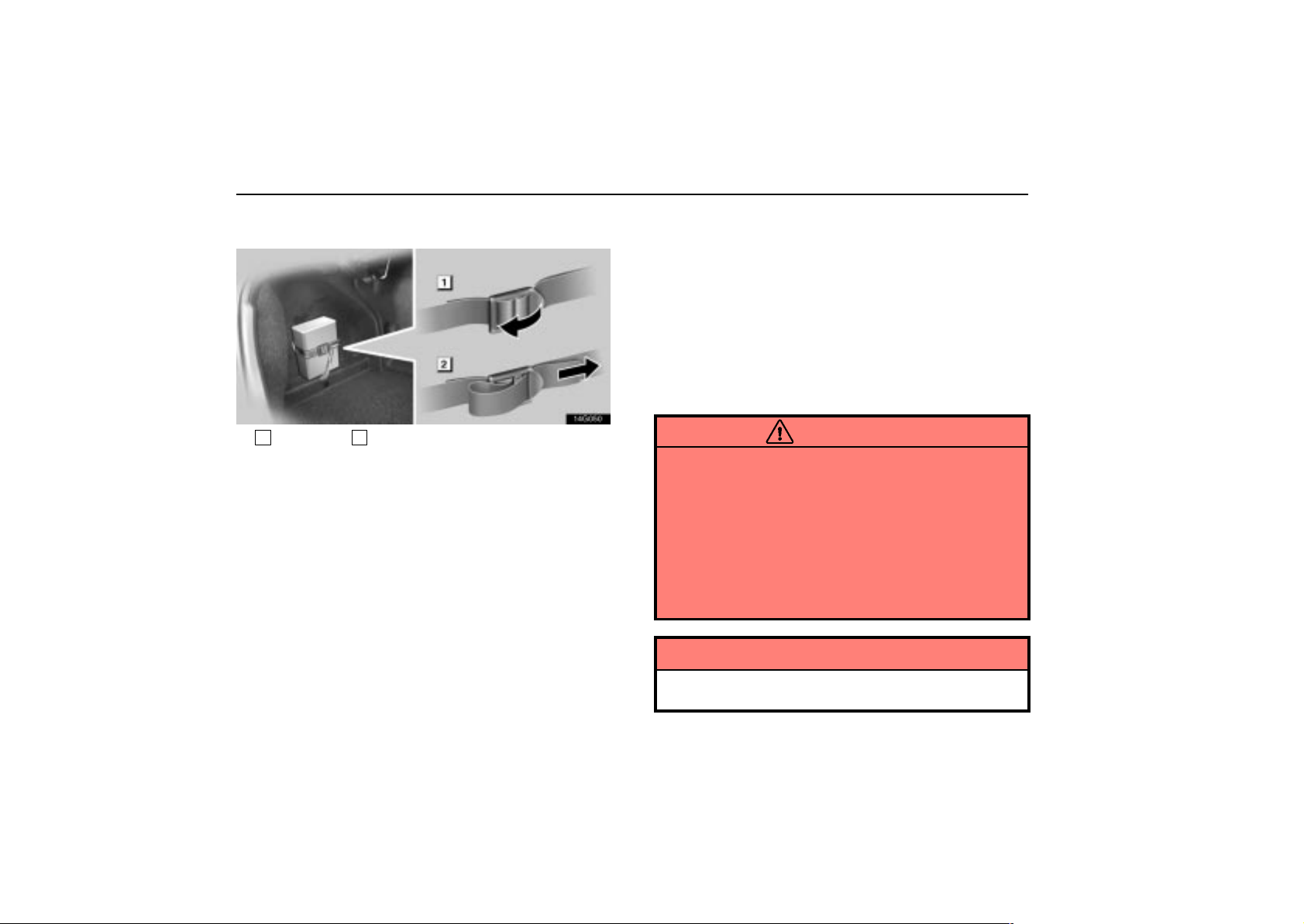
INTERIOR EQUIPMENT
FIRST–AID KIT HOLDER
14G050
1
To loosen 2To tighten
This belt is designed to hold the first–aid kit.
To loosen: Pull the buckle forward.
To tighten: Pull on the belt.
Make sure the first–aid kit is securely held.
LUGGAGE STOWAGE
PRECAUTIONS
When stowing luggage or cargo in the vehicle, observe
the following:
Put luggage or cargo in the trunk when at all possible. Be
sure all items are secured in place.
Be careful to keep the vehicle level. Placing the weight as
far forward as possible helps maintain vehicle balance.
For better fuel economy , do not carry unnecessary weight.
CAUTION
Do not place anything on the package tray behind the
rear seatback. Such items may be thrown about and
possibly injure people in the vehicle during sudden
braking or in an accident.
Do not drive with objects left on top of the instrument
panel. They may interfere with the driver’s field of
view. Or they may move during sharp vehicle
acceleration or turning, and impair the driver’s
control of the vehicle. In an accident they may injure
the vehicle occupants.
NOTICE
64
Do not load the vehicle beyond the vehicle capacity
weight specified on the tire pressure label.
Page 82

SECTION 1 –
INSTRUMENTS AND CONTROLS
Exterior equipment
Hood 66. . . . . . . . . . . . . . . . . . . . . . . . . . . . . . . . . . . . . . . . . . . . . . . . . . . .
Trunk lid 67. . . . . . . . . . . . . . . . . . . . . . . . . . . . . . . . . . . . . . . . . . . . . . . . .
Fuel tank cap 69. . . . . . . . . . . . . . . . . . . . . . . . . . . . . . . . . . . . . . . . . . . . .
Moon roof 70. . . . . . . . . . . . . . . . . . . . . . . . . . . . . . . . . . . . . . . . . . . . . . . .
5
65
Page 83
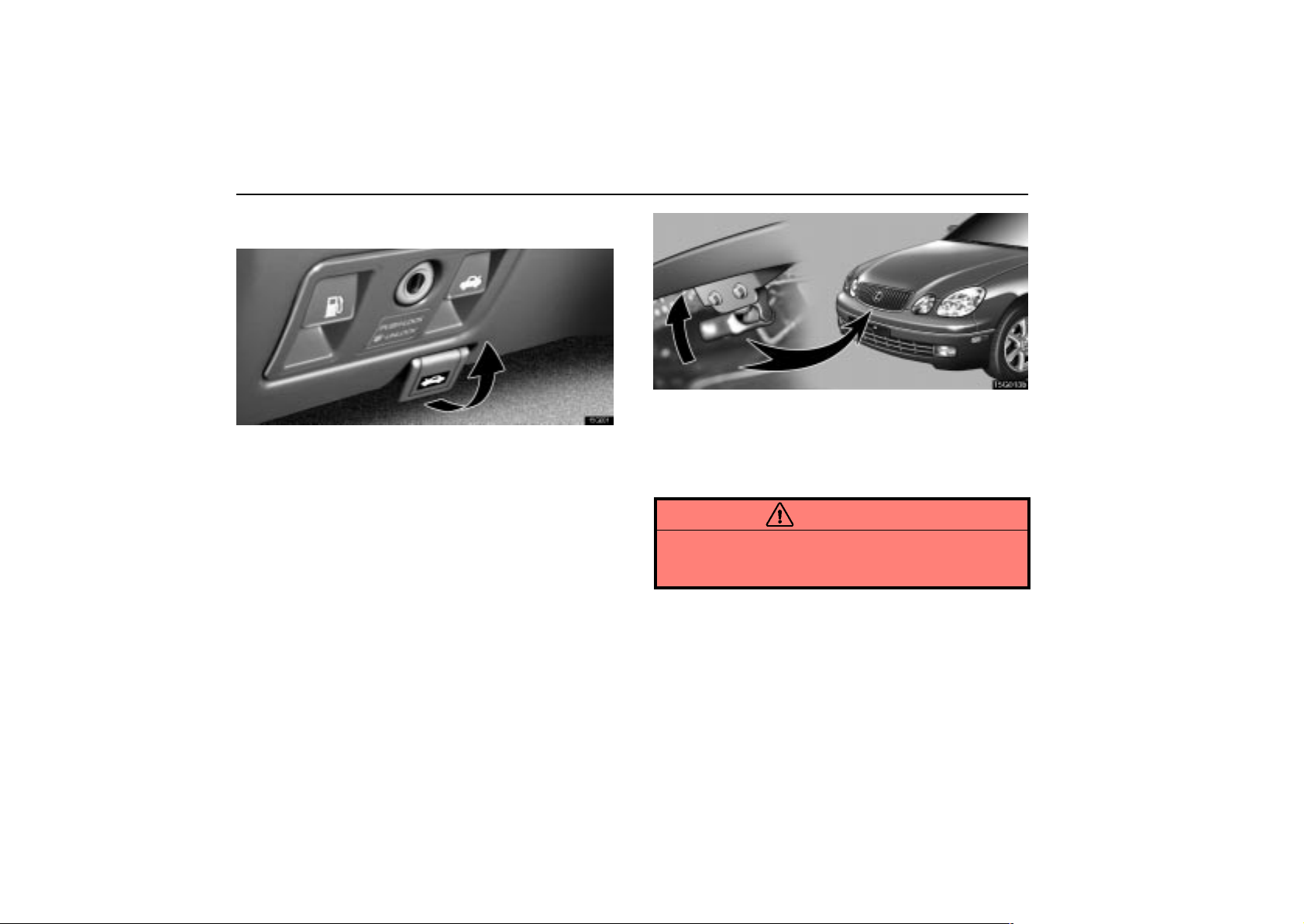
EXTERIOR EQUIPMENT
HOOD
15G001
1. To open the hood, pull the hood lock release lever
under the instrument panel. The hood will spring up
slightly.
15G013b
2. Insert your fingers under the hood, push up the
auxiliary catch lever and lift the hood.
Before closing the hood, check to see that you have not
forgotten any tools, rags, etc. Then lower the hood and make
sure it locks.
CAUTION
Before driving, be sure that the hood is closed and
securely locked. Otherwise, the hood may open
unexpectedly while driving and an accident may occur.
66
Page 84
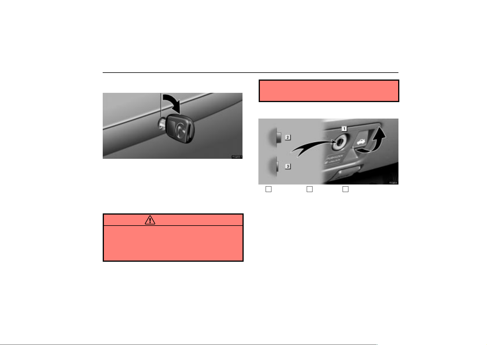
EXTERIOR EQUIPMENT
TRUNK LID
15G003–1
To unlock the trunk lid, insert the master key and turn it
clockwise.
To close the trunk lid, lower it and press down on it. After
closing the trunk lid, try pulling it up to make sure it is securely
closed.
The trunk lid can be unlocked using the wireless remote control
key. For details, see page 15.
CAUTION
Keep the trunk lid closed while driving. This not only
keeps the luggage from being thrown out, but also
prevents exhaust gases from entering the vehicle.
Always lock the trunk lid and all doors, and keep
away the vehicle keys out of children’s reach.
Never leave children unattended in the vehicle. Un
supervised children may lock themselves in the
vehicles or tru n k a n d s u ffer serious injuries or death.
Trunk lid opener
15G004
1
Main switch 2Operative 3Inoperative
To open the trunk lid while sitting in the driver’s seat, pull
the lever with the main switch not pushed in.
67
Page 85
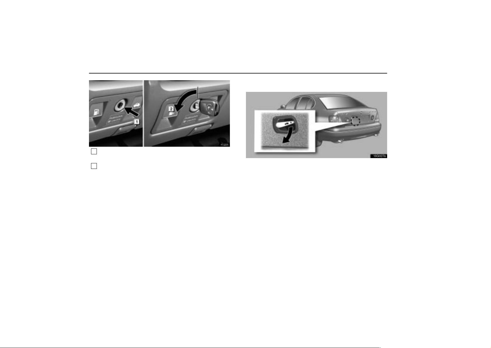
EXTERIOR EQUIPMENT
15G005
1
If you do not want to activate the trunk lid opener
system, push in the main switch.
2
To activate the system, insert the master key and turn
it counterclockwise.
To protect things put in the trunk, when you have your vehicle
parked, push in the main switch.
Internal trunk release handle
15g027a
If a person is locked in the trunk, he/she can pull down the
phosphorescent handle on the inside of trunk lid to open
the trunk lid.
The phosphorescent (glow–in–the–dark) handle will continue
to glow for a time after the trunk lid is closed. Exposing the
handle to stronger light will cause it to glow longer.
68
Page 86
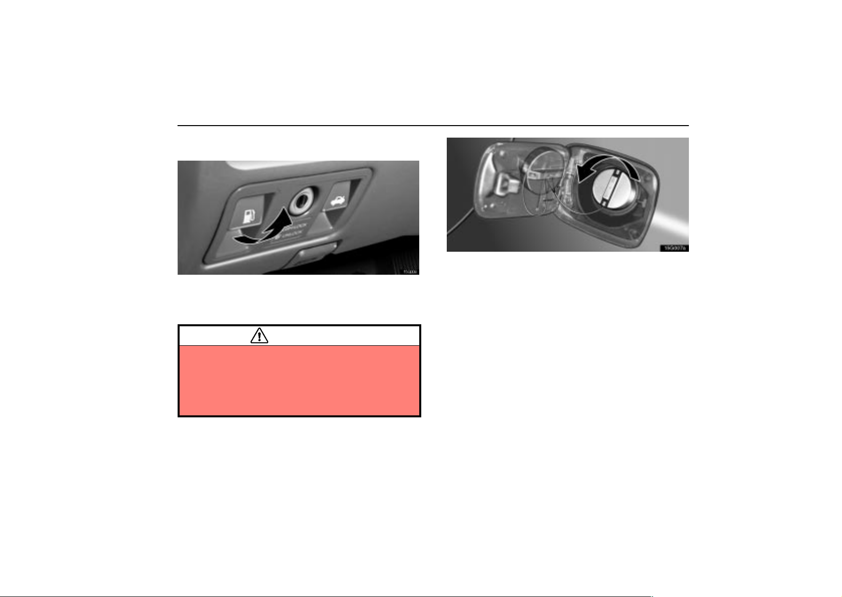
FUEL TANK CAP
15G006
1. To open the fuel filler door, pull the lever under the
instrument panel.
When refueling, turn off the engine.
CAUTION
Do not smoke, cause sparks or allow open flames
when refuelling. The fumes are flammable.
When opening the cap, do not remove the cap
quickly. In hot weather, fuel under pressure could
cause injury by spraying out of the filler neck if the
cap is suddenly removed.
EXTERIOR EQUIPMENT
15G007a
2. To remove the fuel tank cap, turn the cap slowly
counterclockwise, then pause slightly before removing it.
The removed cap can be stored on the back side of the fuel
filler door.
It is not unusual to hear a slight swoosh when the cap is
opened. When installing the cap, turn the cap clockwise until
you hear a click.
If the cap is not installed securely, the malfunction indicator
lamp comes on. Make sure the cap is installed securely.
The indicator lamp goes off after driving several times. If the
indicator lamp does not go off, contact your Lexus dealer as
soon as possible.
69
Page 87
EXTERIOR EQUIPMENT
CAUTION
Make sure the cap is installed securely to prevent fuel
spillage in the event of an accident.
Use only a genuine Lexus fuel tank cap for
replacement. It is designed to regulate fuel tank
pressure.
In case the opener is not actuated
15G008a
Pull the manual lever toward the back.
This is used in case the fuel filler door cannot be opened due
to a discharged battery or other trouble.
MOON ROOF
15G011–1
1
Open 2Close
To slide open the moon roof, push the switch toward the
back. The moon roof will fully open. To stop partway,
push the same switch or ”TILT” switch.
The sun shade can be opened or closed manually . However,
if you open the moon roof, the sun shade will be opened with
the moon roof.
To close the moon roof, push the switch toward the front.
The moon roof will fully close. To stop partway, push the
same switch or ”TILT” switch.
70
Page 88
15G012–1
1
Tilt up 2Lower
To tilt up the rear end of the moon roof fully, push the
switch on the rear side or on the front side to lower it.
To operate the moon roof, the ignition key must be in the ”ON”
position.
Key off operation: Even if the ignition key is turned to the
”ACC” or ”LOCK” position, the moon roof can be operated until
any of the doors is opened (or for about 45 seconds).
EXTERIOR EQUIPMENT
Operating the moon roof from outside the
vehicle
The moon roof can be closed or opened using an ignition key.*
Insert the ignition key into the key hole on the driver’s
door.
To close the moon roof: Turn the key in the locking direction
and hold it.
After the door is locked, the moon roof begins to close. To stop
in the middle, return the key.
To open the moon roof: Turn the key in the unlocking
direction and hold it.
After the door is unlocked, the moon roof begins to open. To
stop in the middle, return the key.
NOTE: *This feature can be set inoperative, or sliding open
or tilting up can be selected. Ask your Lexus dealer for
details.
71
Page 89

EXTERIOR EQUIPMENT
Jam protection function
If something gets caught into the roof opening during closing
operation, the moon roof stops and is open.
If the moon roof receives a strong impact, this function may
work even if nothing is caught.
CAUTION
To avoid serious personal injury, you must do the
following.
While the vehicle is moving, always keep the heads,
hands and other parts of the bodies of all occupants
away from the roof opening. Otherwise, they could
be seriously injured if the vehicle stops suddenly or
if the vehicle is involved in an accident.
Before you close the moon roof, always make sure
there is nobody around the moon roof. You must also
make sure nobody places his or her head, hands and
other parts of the body in the roof opening. If
someone’s neck, head or hands get caught in the
closing roof, it could result in a serious injury. When
anyone closes the moon roof, first make sure it is safe
to do so.
Be sure to remove the ignition key or turn the ignition
switch to the “LOCK” position when you leave your
vehicle.
Never leave anyone (particularly a small child) alone
in your vehicle, especially with the ignition key still
inserted or with the ignition switch in a position other
than “LOCK”. Otherwise, he/she could use the moon
roof switches and get trapped in the roof opening.
Unattended person ( p articularly a small child) can be
involved in a serious accident.
Never sit on top of the vehicle around the roof
opening.
Never try jamming any part of your body to activate
the jam protection function intentionally.
The jam protection function may not work if
something gets caught just before the moon roof
fully closed.
72
Page 90

SECTION 1 –
INSTRUMENTS AND CONTROLS
Comfort adjustment
Seats 74. . . . . . . . . . . . . . . . . . . . . . . . . . . . . . . . . . . . . . . . . . . . . . . . . . .
Head restraints 79. . . . . . . . . . . . . . . . . . . . . . . . . . . . . . . . . . . . . . . . . . .
Tilt and telescopic steering wheell80. . . . . . . . . . . . . . . . . . . . . . . . . . .
Outside rear view mirrors 82. . . . . . . . . . . . . . . . . . . . . . . . . . . . . . . . . .
Inside rear view mirror 83. . . . . . . . . . . . . . . . . . . . . . . . . . . . . . . . . . . . .
Seat belts 88. . . . . . . . . . . . . . . . . . . . . . . . . . . . . . . . . . . . . . . . . . . . . . . .
SRS airbags 97. . . . . . . . . . . . . . . . . . . . . . . . . . . . . . . . . . . . . . . . . . . . .
Child restraint 111. . . . . . . . . . . . . . . . . . . . . . . . . . . . . . . . . . . . . . . . . . .
Driving position memory system 130. . . . . . . . . . . . . . . . . . . . . . . . . . .
6
73
Page 91
COMFORT ADJUSTMENT
SEATS
While the vehicle is being driven, all vehicle occupants should
have the seatback upright, sit well back in the seat and properly
wear the seat belts provided.
CAUTION
Do not drive the vehicle unless the occupants are
properly seated. Do not allow passengers to sit in the
luggage compartment or cargo area. Persons not
properly seated and/or properly restrained by seat
belts can be severely injured in the event of
emergency braking or a collision.
During driving, do not allow passengers to stand up
or move around between seats. Otherwise, severe
injuries can occur in the event of emergency braking
or a collision.
Front seat precautions
Driver seat
CAUTION
The driver airbag deploys with considerable force, and
can cause death or serious injury especially if the driver
is very close to the airbag. The National Highway Traffic
Safety Administration (”NHTSA”) advises:
Since the risk zone for driver airbag is the first 50–75
mm (2–3 in.) of inflation, placing yourself 250 mm (10 in.)
from your driver airbag provides you with a clear margin
of safety. This distance is measured from the center of
the steering wheel to your breastbone. If you sit less
than 250 mm (10 in.) away now, you can change your
driving position in several ways:
Move your seat to the rear as far as you can while still
reaching the pedals comfortably.
Slightly recline the back of the seat. Although vehicle
designs vary, many drivers can achieve the 250 mm
(10 in.) distance, even with the driver seat all the way
forward, simply by reclining the back of the seat
somewhat. If reclining the back of your seat makes
it hard to see the road, raise yourself by using a firm,
non–slippery cushion, or raise the seat if your vehicle
has that feature.
74
Page 92
COMFORT ADJUSTMENT
If your steering wheel is adjustable, tilt it downward.
This points the airbag toward your chest instead of
your head and neck.
The seat should be adjusted as recommended by
NHTSA above, while still maintaining control of the foot
pedals, steering wheel, and your view of the instrument
panel controls.
Front passenger seat
CAUTION
The front passenger airbag also deploys with
considerable force, and can cause death or serious
injury especially if the front passenger is very close to
the airbag. The front passenger seat should be as far
from the airbag as possible with the seatback adjusted,
so the front passenger sits upright.
Front seats
CAUTION
The side airbags are installed in the driver and front
passenger seats. Observe the following precautions.
Do not lean against the front door when the vehicle
is in use, since the side airbag inflates with
considerable speed and force. Otherwise, you may
be killed or severely injured.
Do not use seat accessories which cover the parts
where the side airbags inflate. Such accessories may
prevent the side airbags from activating correctly,
causing death or serious injury.
Do not modify or replace the seats or upholstery of
front seats equipped with side airbags. Such
changes may prevent the side airbags from
activating correctly , disable the system, or cause the
side airbags to inflate accidentally , re sulting in death
or serious injury.
75
Page 93
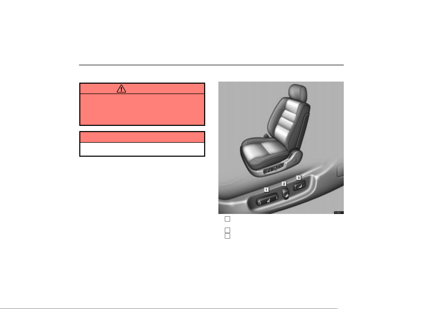
COMFORT ADJUSTMENT
Seat adjustment precautions
CAUTION
Do not adjust the seat while the vehicle is moving as
the seat may unexpectedly move and cause the
driver to lose control of the vehicle.
Be careful that the seat does not hit a passenger,
luggage, or the rear seat.
NOTICE
Do not operate the control switch in more than one
dimension at a time. It may cause electrical overload.
Adjusting front seats
16G001–1
1
Seat position control switch, seat cushion angle and
height control switch
2
Seatback angle control switch
3
Lumbar support control switch
76
Page 94
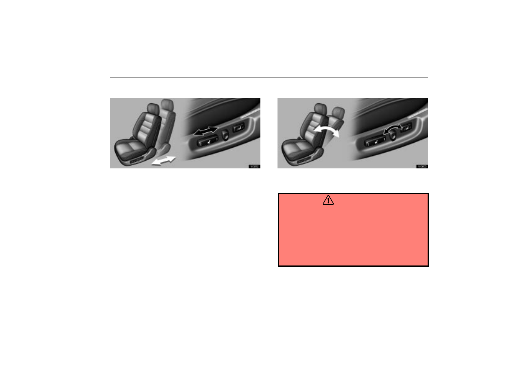
COMFORT ADJUSTMENT
Adjusting seat position
16G002
Move the control switch in the desired direction.
Releasing the switch will stop the seat in that position. Do not
place anything under the seat, as this might interfere with the
seat movement.
Adjusting seatback angle
16G003
Move the control switch in the desired direction.
Releasing the switch will stop the seatback in that position.
CAUTION
To reduce the risk of sliding under the lap belt during a
collision, avoid reclining the seatback any more than
needed. The seat belts provide maximum protection in
a frontal or rear collision when the driver and the
passenger are sitting up straight and well back in the
seats. If you are reclined, the lap belt may slide past
your hips and apply restraint forces directly to the
abdomen. In the event of a frontal collision, the more the
seat is reclined, the greater the risk of personal injury.
77
Page 95
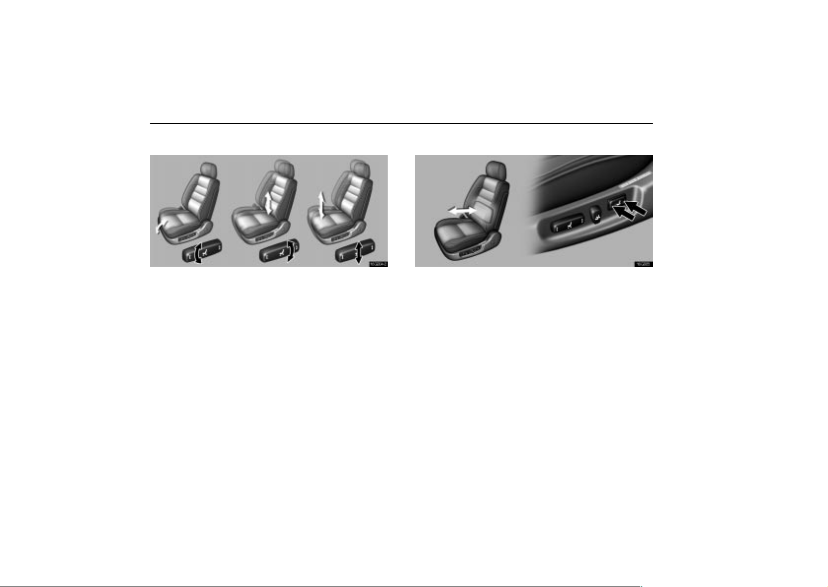
COMFORT ADJUSTMENT
Adjusting seat cushion angle and height
16G004–2
Move the control switch in the desired direction.
Releasing the switch will stop the seat cushion in that position.
Adjusting lumbar support
16G005
Push the control switch on either side.
The amount of lumbar support will change while the switch is
pushed.
78
Page 96
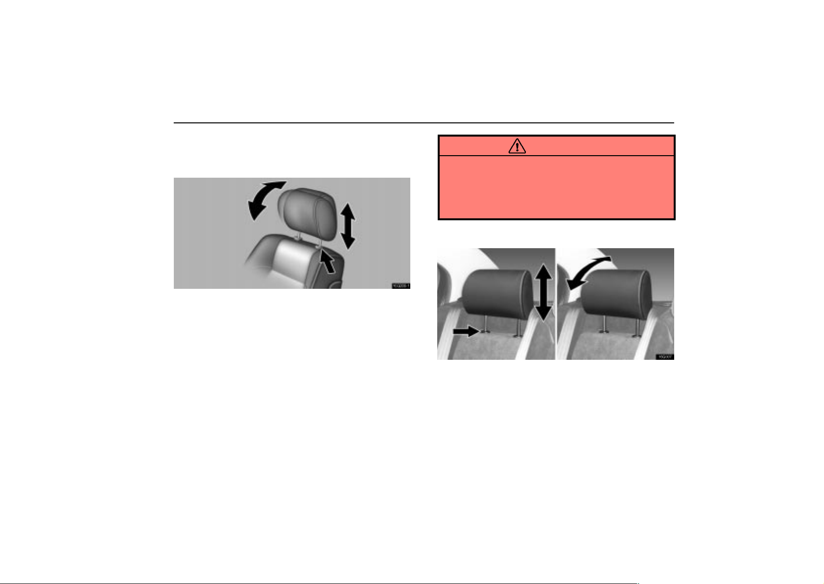
COMFORT ADJUSTMENT
HEAD RESTRAINTS
Front seats
16G006–1
To raise the head restraint, pull it up. To lower it, press the
lock release button and push the head restraint down. To
move the head restraint forward or rearward, pull or push
on the top.
The head restraint is most effective when it is close to your
head. Therefore, using a cushion on the seatback is not
recommended.
CAUTION
Adjust the center of the head restraint so that it is
closest to the top of your ears.
After adjusting the head restraint, make sure it is
locked in position.
Do not drive with the head restraints removed.
Rear seats
16G007
Outside rear seats
To raise the head restraint, pull it up. To lower it, press the
lock release button and push the head restraint down. To
move the head restraint forward or rearward, pull or push
on the top.
79
Page 97
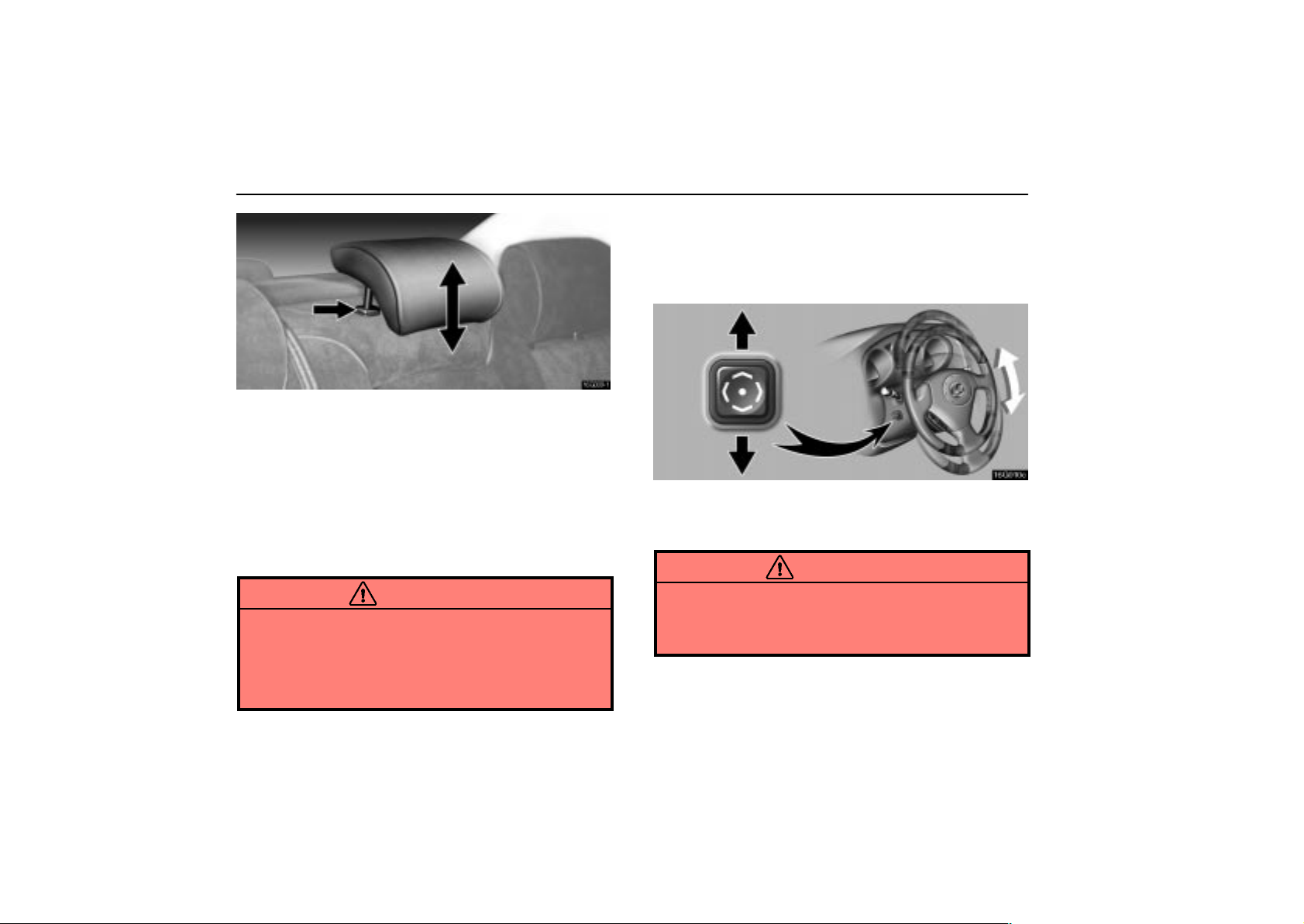
COMFORT ADJUSTMENT
16G009–1
TILT AND TELESCOPIC STEERING
WHEEL
Adjustment of steering wheel tilt
Center rear seat
To raise the head restraint, pull it up. To lower it, press the
lock release button and push the head restraint down.
Center rear head restraint: When an occupant sits on the
center rear seat, always pull up the head restraint to the lock
position.
The head restraint is most effective when it is close to your
head. Therefore, using a cushion on the seatback is not
recommended.
CAUTION
Adjust the center of the head restraint so that it is
closest to the top of your ears.
After adjusting the head restraint, make sure it is
locked in position.
Do not drive with the head restraints removed.
80
16G010c
To adjust the tilt of the steering wheel, push the control
switch upward or downward to set it to the desired
position.
CAUTION
Do not adjust the steering wheel while the vehicle is
moving. Doing so may cause the driver to mishandle
the vehicle and an accident may occur resulting in death
or serious injuries.
Page 98
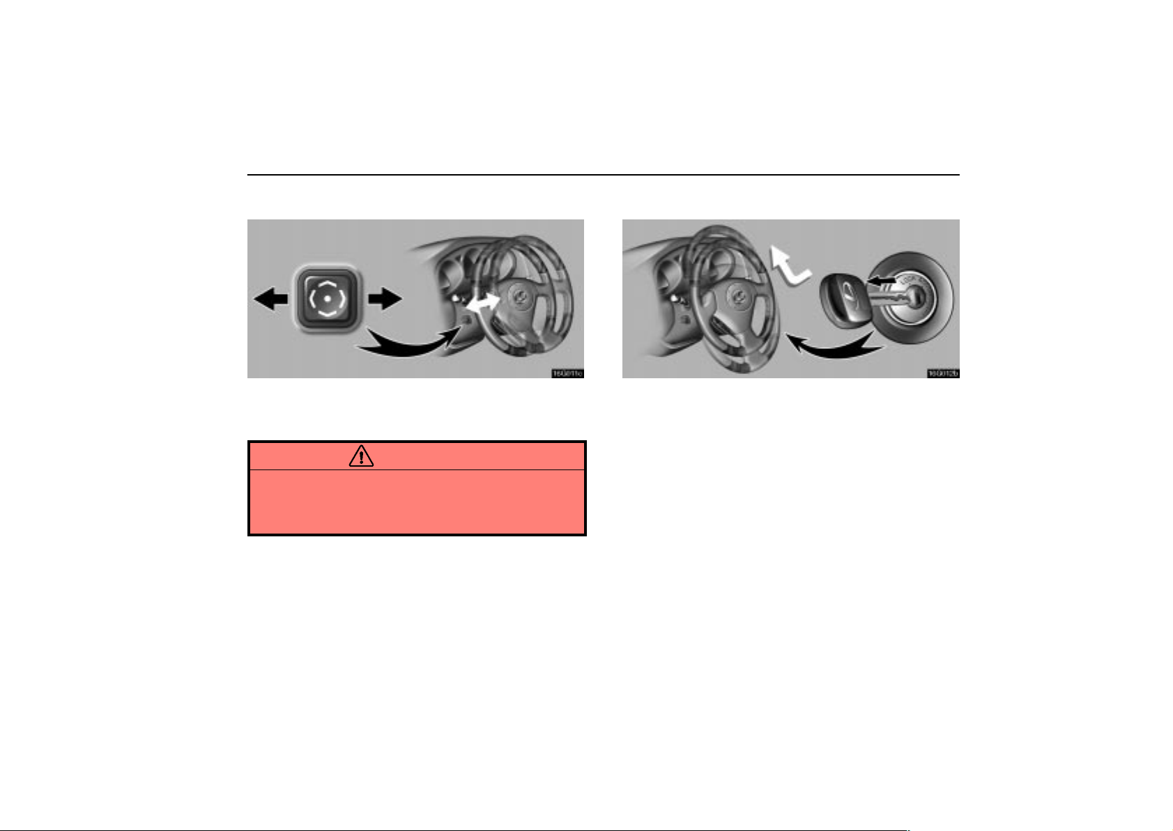
COMFORT ADJUSTMENT
Adjustment of telescopic steering column
16G011c
To adjust the steering column length, push the control
switch forward or backward to set the steering wheel to
the desired position.
CAUTION
Do not adjust the steering column while the vehicle is
moving. Doing so may cause the driver to mishandle
the vehicle and an accident may occur resulting in death
or serious injuries.
Auto tilt away*
16G012b
When the ignition key is removed, the steering column
moves forward away from the driver and also tilts up for
easy exit and entry.
When the key is inserted in the ignition switch, the steering
column returns to the previously set position.
NOTE: *This feature can be deactivated. Ask your Lexus
dealer for details.
81
Page 99
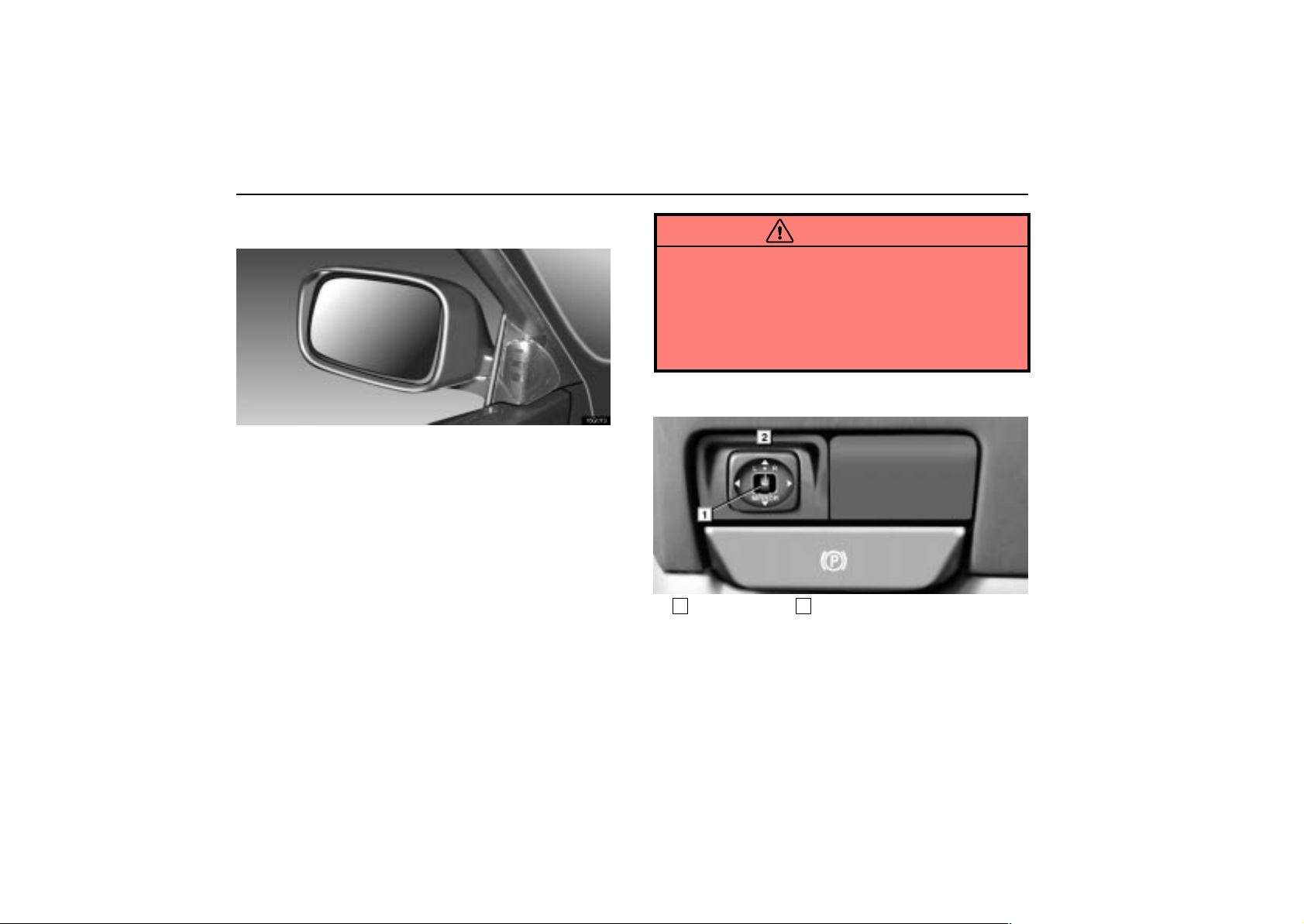
COMFORT ADJUSTMENT
OUTSIDE REAR VIEW MIRRORS
16G013
Adjust the mirror so that you can just see the side of your
vehicle in the mirror.
Be careful when judging the size or distance of any object seen
in the outside rear view mirror on the passenger’s side
because it is a convex mirror. Any object seen in a convex
mirror will look smaller and farther away than if seen in a normal
flat mirror.
When the inside rear view mirror darkens in ”AUTO” mode, the
outside rear view mirrors also darken to reduce the reflection
of the headlights of the following vehicle. For details, see
”Inside rear view mirror” on page 83.
When you push the rear window defogger switch, the heater
panels in the outside rear view mirrors will quickly clear the
mirror surface. (See “Rear window and outside rear view
mirror defogger switch” on page 31.)
CAUTION
Do not adjust the mirror while the vehicle is moving.
Doing so may cause the driver to mishandle the
vehicle and an accident may occur resulting in death
or serious injuries.
Since the mirror surfaces can get hot, do not touch
them when the rear window and outside rear view
mirror defogger switch is on.
Power rear view mirror control
16L017-1
1
Master switch 2Control switch
To adjust the power rear view mirror, first place the master
switch at ”L” (left) or ”R” (right), and push the control
switch on the desired side.
The power rear view mirrors can be adjusted when the key is
in the ”ACC” or ”ON” position.
82
Page 100
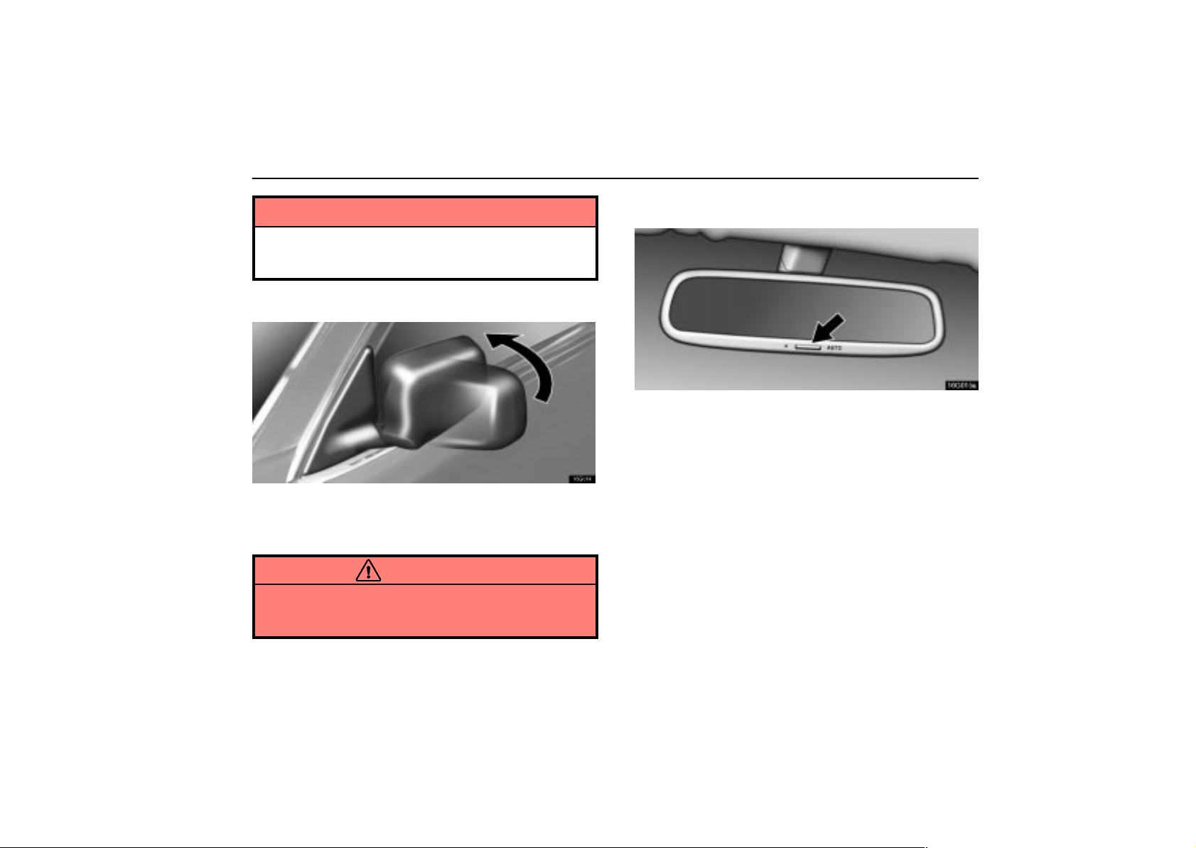
COMFORT ADJUSTMENT
NOTICE
If ice should jam the mirror, do not operate the control
or scrape the mirror face. Use a spray de–icer to free the
mirror.
Folding rear view mirrors
16G014
To fold the rear view mirror, push backward.
The rear view mirrors can be folded backward for parking in
compact areas.
CAUTION
Do not drive with the mirrors folded backward. Both the
driver and passenger side rear view mirrors must be
extended and properly adjusted before driving.
INSIDE REAR VIEW MIRROR
16G015a
Adjust the mirror so that you can just see the rear of your
vehicle in the mirror.
Pushing the switch changes the mode between ”AUTO”
and ”DAY”.
The indicator comes on when the ”AUTO” mode is selected.
”DAY” mode: The mirror surface is normal.
”AUTO” mode: If the mirror detects light from the
headlights of the vehicle behind you, the mirror surface
darkens slightly to reduce the reflected light.
When the inside rear view mirror surface changes, the outside
rear view mirror surfaces will also become darker.
When the ignition key is inserted and turned on, the inside rear
view mirror always turns on in the ”AUTO” mode.
83
 Loading...