

Page 1
–AIR CONDITIONING AIR CONDITIONING SYSTEM
AC–1
AC2810
AC2811
AIR CONDITIONING SYSTEM
AC09C–01
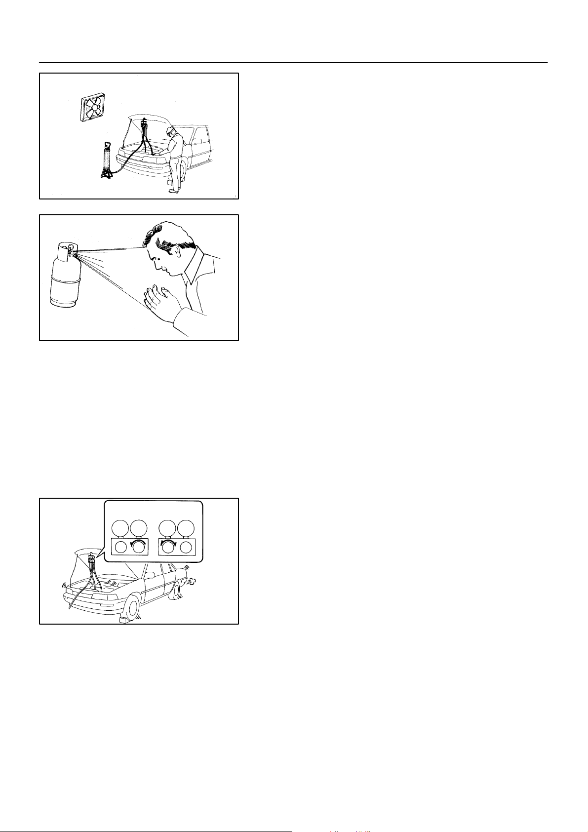
PRECAUTION
1. DO NOT HANDLE REFRIGERANT IN AN ENCLOSED
AREA OR NEAR AN OPEN FLAME
2. ALWAYS WEAR EYE PROTECTION
3. BE CAREFUL NOT TO GET LIQUID REFRIGERANT IN
YOUR EYES OR ON YOUR SKIN
If liquid refrigerant gets in your eyes or on your skin.
(a) Wash the area with lots of cool water.
CAUTION:
Do not rub your eyes or skin.
(b) Apply clean petroleum jelly to the skin.
(c) Go immediately to a physician or hospital for professional
treatment.
4. NEVER HEAT CONTAINER OR EXPOSE IT T O NAKED
FLAME
5. BE CAREFUL NOT TO DROP CONTAINER AND NOT
TO APPL PHYSICAL SHOCKS TO IT
Wrong
1997 LEXUS ES300 (RM511U)
Okay
LO HILO HI
N11084
6. DO NOT OPERATE COMPRESSOR WITHOUT
ENOUGH REFRIGERANT IN REFRIGERANT SYSTEM
If there is not enough refrigerant in the refrigerant system oil lubrication will be insufficient and compressor burnout may occur ,
so that take care to avoid this, necessary care should be taken.
7. DO NOT OPEN HIGH PRESSURE MANIFOLD VALVE
WHILE COMPRESSOR IS OPERATING
If the high pressure valve is opened, refrigerant flows in the reverse direction and could cause the charging cylinder to rupture, so open and close the only low pressure valve.
8. BE CAREFUL NOT TO OVERCHARGE SYSTEM WITH
REFRIGERANT
If refrigerant is overcharged, it causes problems such as insufficient cooling, poor fuel economy, engine overheating etc.
1558Author: Date:
Page 2

AC–2
–AIR CONDITIONING AIR CONDITIONING SYSTEM
9. SUPPLEMENTAL RESTRAINT SYSTEM (SRS)
The Lexus ES300 is equipped an SRS (Supplemental Restraint
System) such as the driver and passenger air bag. Failure to
carry out service operations the correct sequence could cause
the SRS to unexpectedly deployed during servicing, possibly
leading to a serious accident. Further, if a mistake is made in
servicing the SRS, it is possible the SRS may fail to operate
when required. Before servicing (including removal or installation of parts, inspection or replacement), be sure to read the following item carefully, then follow the correct procedure described in the repair manual.
1997 LEXUS ES300 (RM511U)
1559Author: Date:
Page 3
–AIR CONDITIONING AIR CONDITIONING SYSTEM
ON–VEHICLE INSPECTION
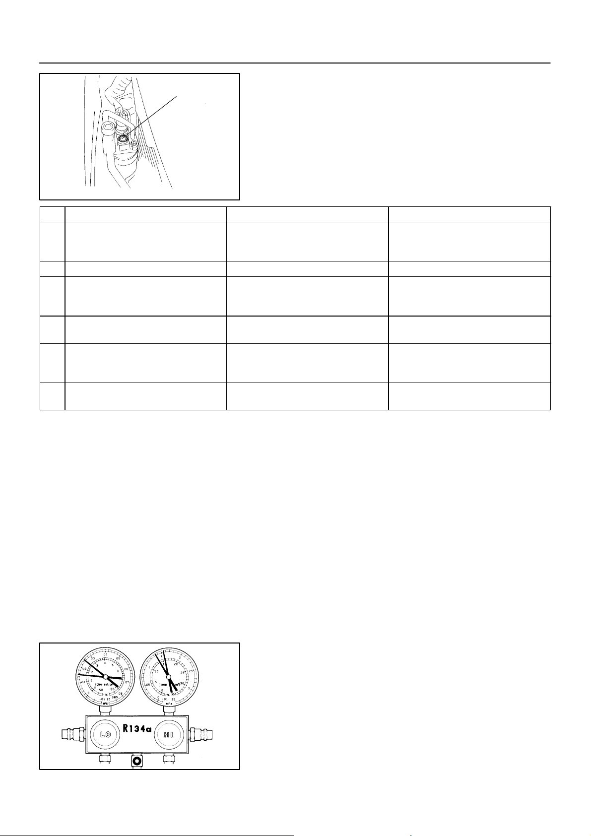
Sight Glass
N20242
Item Symptom Amount o f refrigerant Remedy
1 Bubbles present in sight glass *Insufficient
2 No bubbles present i sight glass None, sufficient or too much Refer to item 3 and 4
No temperature difference between com-
3
pressor inlet and outlet
Temperature between compressor inlet and
4
outlet is noticeably different
Immediately after air conditioning is turned
5
off, refrigerant in sight glass stays clear
When air conditioning is turned off, refriger-
6
ant foams and then stays clear
1. INSPECT REFRIGERANT VOLUME
Observe the sight glass on the liquid tube.
Test conditions:
Running engine at 1,500 rpm
Blower speed control switch set at ”HI”
A/C switch ON
Temperature control set at ”MAX. COOL”
Fully open doors
(1) Check for gas leakage with gas leak detector and repair if necessary
(2) Add refrigerant until bubbles disappear
(1) Check for gas leakage with gas leak de-
Empty or nearly empty
Correct or too much Refer to items 5 and 6
Too much
Correct –
tector and repair if necessary
(2) Add refrigerant until bubbles disappear
(1) Discharge refrigerant
(2) Evacuate air and charge proper amount
of new refrigerant
HINT:
*: Bubbles in the sight glass with ambient temperatures higher
than usual can be considered normal if cooling is sufficient.
2. INSPECT REFRIGERANT PRESSURE WITH MANIFOLD GAUGE SET
This is a method in witch the trouble is located by using a manifold gauge set. Read the manifold gauge pressure when the
these conditions are established.
Test conditions:
Temperature at the air inlet with the switch set
at RECIRC is 30 – 35 °C (86 – 95 °F)
Engine running at 1,500 rpm
Blower speed control set at ”HI”
Temperature control set at ”MAX COOL”
AC–3
AC2SY–01
1997 LEXUS ES300 (RM511U)
I01386
(1) Normally functioning refrigeration system
Gauge reading:
Low pressure side: 0.15 – 0.25 MPa (1.5 – 2.5 kgf/cm
High pressure side: 0.15 – 0.25 MPa (1.5 – 2.5 kgf/cm
1560Author: Date:
2
)
2
)
Page 4
AC–4
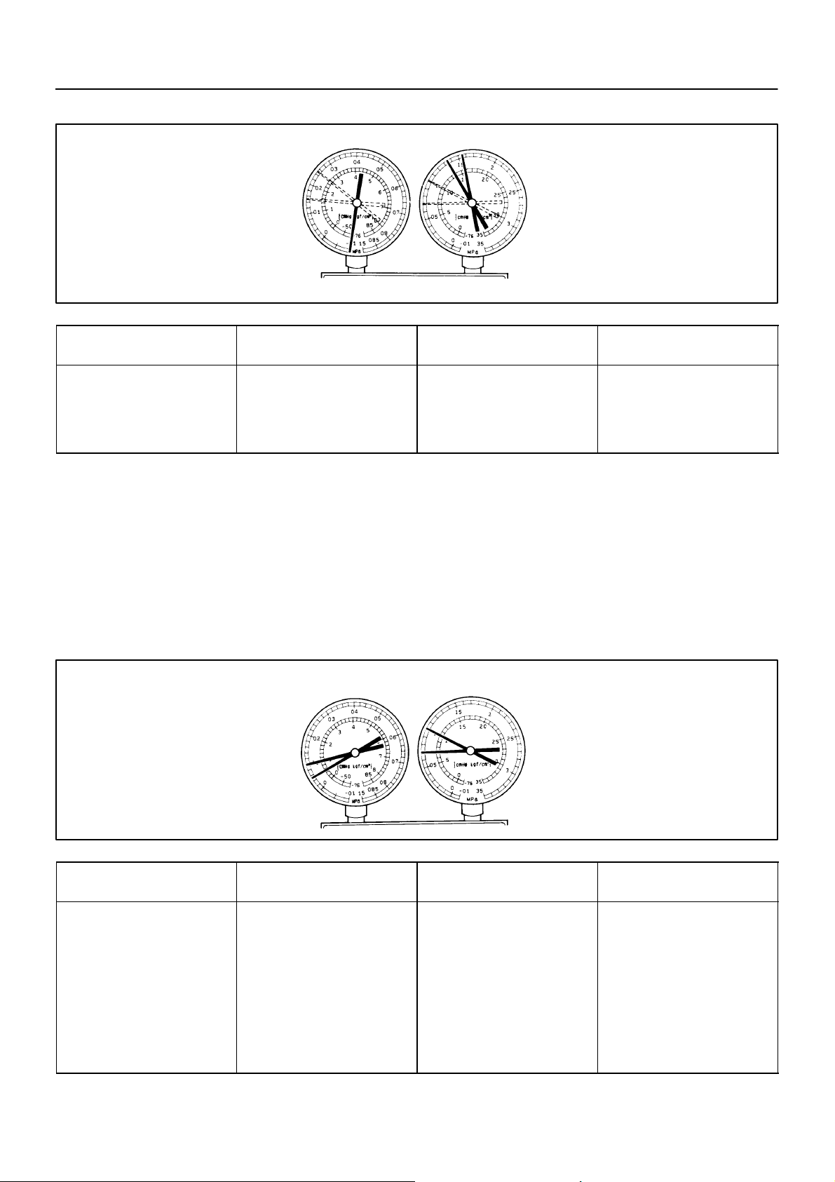
Condition: Periodically cools and then fails to cool
–AIR CONDITIONING AIR CONDITIONING SYSTEM
(2) Moisture present in refrigeration system.
I01387
Symptom seen in
refrigeration system
During operation, pressure on low
pressure side sometimes become
a vacuum and sometime normal
Condition: Insufficient cooling
Probable cause Diagnosis Remedy
Moisture entered in refrigeration
system freezes at expansion valve
orifice and temporarily stops cycle,
but normal state is restored after a
time when the ice melts
(3) Insufficient cooling
Drier in oversaturated state
Moisture in refrigeration system
freezes at expansion valve orifice
and blocks circulation of refrigerant
(1) Replace receiver
(2) Remove moisture in cycle
through repeatedly evacuating air
(3) Charge proper amount of new
refrigerant
Symptom seen in
refrigeration system
Pressure low on both low and
high pressure sides
Bubbles seen in sight glass continuously
Insufficient cooling performance
1997 LEXUS ES300 (RM511U)
Probable cause Diagnosis Remedy
Gas leakage at some place in refrigeration system
Insufficient refrigerant in system
Refrigerant leaking
I01388
(1) Check for gas leakage with gas
leak detector and repair if necessary
(2) Charge proper amount of refrigerant
(3) If indicated pressure value is
near 0 when connected to gauge,
create the vacuum after inspecting
and repairing the location of the
leak
1561Author: Date:
Page 5
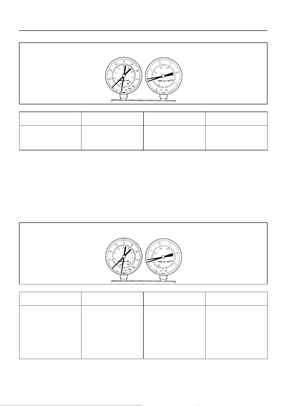
Condition: Insufficient cooling
AC–5
–AIR CONDITIONING AIR CONDITIONING SYSTEM
(4) Poor circulation of refrigerant
I01389
Symptom seen in
refrigeration system
Pressure low in both low and
high pressure sides
Frost on tube from receiver to
unit
Refrigerant flow obstructed by dirt
in receiver
Probable cause Diagnosis Remedy
Receiver clogged Replace receiver
(5) Refrigerant does not circulate
Condition: Does not cool (Cools from time to time in some cases)
Symptom seen in
refrigeration system
Vacuum indicated on low pressure side, very low pressure indicated on high pressure side
Frost or dew seen on piping before and after receiver/ drier or expansion valve
1997 LEXUS ES300 (RM511U)
Probable cause Diagnosis Remedy
Refrigerant flow obstructed by
moisture or dirt in refrigeration system
Refrigerant flow obstructed by
gas leakage from expansion valve
Refrigerant does not circulate
I01449
(1) Check expansion valve
(2) Clean out dirt in expansion
valve by blowing with air
(3) Replace receiver
(4) Evacuate air and charge new
refrigerant to proper amount
(5) For gas leakage from expansion valve, replace expansion
valve
1562Author: Date:
Page 6
AC–6
Condition: Insufficient cooling
–AIR CONDITIONING AIR CONDITIONING SYSTEM
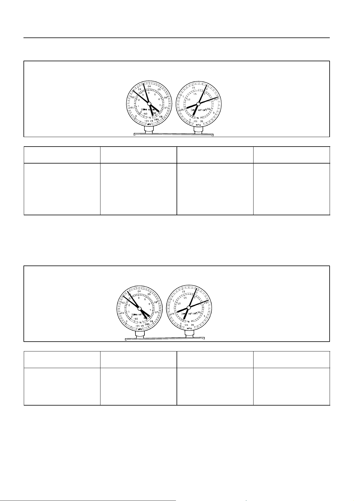
(6) Refrigerant overcharged or insufficient cooling of
condenser
I01390
Symptom seen in
refrigeration system
Pressure too high on both low
and high pressure sides
No air bubbles seen through the
sight glass even when the engine
rpm is lowered
Condition: Insufficient cooling
Probable cause Diagnosis Remedy
Unable to develop sufficient performance due to excessive refrigeration system
Insufficient cooling of condenser
(7) Air present in refrigeration system
Excessive refrigerant in
cycle → refrigerant over charged
Condenser cooling → condenser
fins clogged of condenser fan
faulty
NOTE : These gauge indications are shown when the
refrigeration system has
been opened and the refrigerant charged without vacuum purging.
(1) Clean condenser
(2) Check condenser fan motor
operation
(3) If (1) and (2) are in normal
state, check amount of refrigerant
Charge proper amount of refrigerant
I01392
Symptom seen in
refrigeration system
Pressure too high on both low
and high pressure sides
The low pressure piping hot to
touch
Bubbles seen in sight glass
1997 LEXUS ES300 (RM511U)
Probable cause Diagnosis Remedy
Air entered in refrigeration system
Air present in refrigeration system
Insufficient vacuum purging
(1) Check compressor oil to see if
it is dirty or insufficient
(2) Evacuate air and charge new
refrigerant
1563Author: Date:
Page 7
Condition: Insufficient cooling
AC–7
–AIR CONDITIONING AIR CONDITIONING SYSTEM
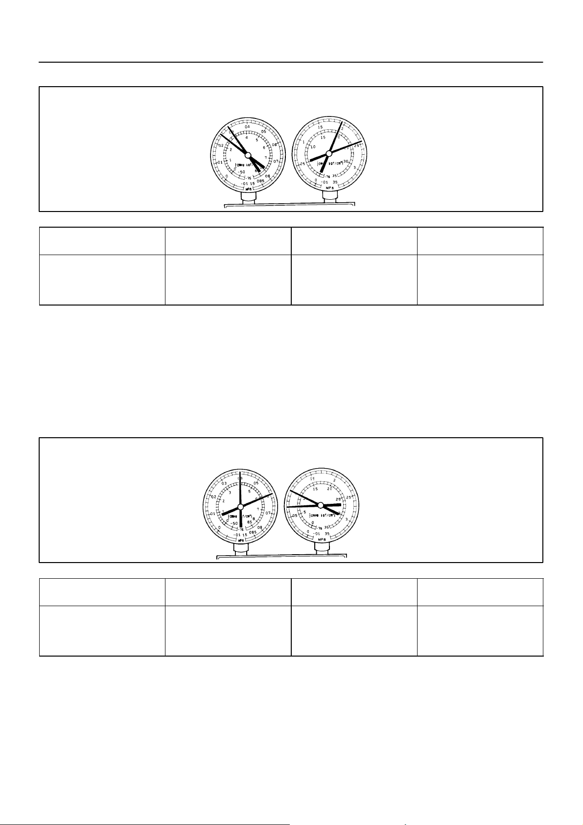
(8) Expansion valve improperly
I01450
Symptom seen in
refrigeration system
Pressure too high on both low
and high pressure sides
Frost or large amount of dew on
piping on low pressure side
Condition: Does not cool
Probable cause Diagnosis Remedy
Trouble in expansion valve
Excessive refrigerant in low
pressure piping
Expansion valve opened too
wide
Check expansion valve
Replace if defective
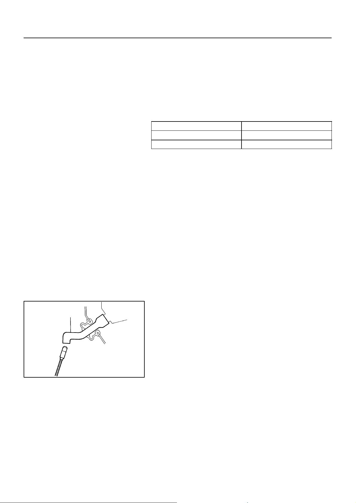
(9) Defective compression compressor
Symptom seen in
refrigeration system
Pressure too high on low and
high pressure sides
Pressure too low on high pressure side
1997 LEXUS ES300 (RM511U)
Probable cause Diagnosis Remedy
Internal leak in compressor
Compression defective
Valve leaking or broken sliding
parts
I01393
Repair or replace compressor
1564Author: Date:
Page 8
AC–8
–AIR CONDITIONING AIR CONDITIONING SYSTEM
3. INSPECT IDLE–UP SPEED
(a) Warm up engine
(b) Inspect idle–up speed when the these conditions are es-
tablished.
Test conditions:
Blower speed control set at ”HI”
Temperature control set at ”MAX COOL”
A/C switch ON
Put gear shift in neutral
Magnetic clutch condition Idle speed
Magnetic clutch not engaged 700 ± 50 rpm
Magnetic clutch engaged 700 ± 50 rpm
If idle speed is not as specified, check IAC valve and air intake
system.
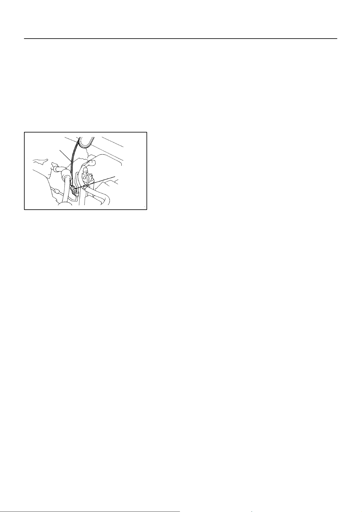
4. INSPECT FOR LEAKAGE OF REFRIGERANT
(a) Perform under these conditions:
Stop engine
Secure good ventilation (If not, the gas leak detec-
tor may react to volatile gases which are not refrigerant, such as evaporated gasoline or exhaust
gas.)
Repeat the test 2 or 3 times
Make sure that there is some refrigerant remaining
in the refrigeration system.
When compressor is OFF: Approx. 392 – 588 kPa
2
(4 – 6 kgf/cm
, 57 – 85 psi)
Drain Hose
1997 LEXUS ES300 (RM511U)
N14519
(b) Bring the gas leak detector close to the drain hose before
performing the test.
HINT:
After the blower motor is stopped, leave the A/C unit for
more than 15 minutes.
Expose the gas leak detector sensor the under the drain
hose.
When bring the gas leak detector close to the drain hose,
make sure that the gas leak detector does not reach to the
volatile gases.
If such reaction is unavoidable, the vehicle must be lifted up.
(c) If gas leak is not detected through the drain hose, remove
the blower linear controller from the A/C unit. Then insert
the gas leak detector sensor into the unit and perform the
test.
1565Author: Date:
Page 9
Gas Leak
Detector
AC–9
–AIR CONDITIONING AIR CONDITIONING SYSTEM
(d) Disconnect the connector and leave the pressure switch
for approx. 20 minutes. Then bring the gas leak detector
close to the pressure switch and perform the test.
(e) Bring the gas leak detector close to the refrigerant lines
and perform the test.
HINT:
Make sure that there is no dirt on joints.
Pressure
Switch
N14517
1997 LEXUS ES300 (RM511U)
1566Author: Date:
Page 10
AC–10
Quick Disconnect
adapter
Vacuum Pump
Vacuum Pump Adapter
Charging Hose
Service Valve
N13795
N13794
–AIR CONDITIONING AIR CONDITIONING SYSTEM
AC09E–01
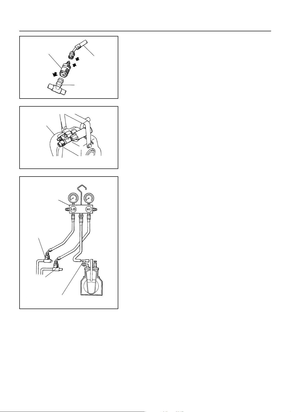
EVACUATING
1. CONNECT QUICK DISCONNECT ADAPTER TO
CHARGING HOSES
2. REMOVE CAPS FROM SERVICE VALVES ON RE-
FRIGERANT LINES
3. SET ON MANIFOLD GAUGE SET
(a) Close both hand valves of manifold gauge set.
(b) Connect the quick disconnect adapter to the service
valves.
4. EVACUATE AIR FROM REFRIGERATION SYSTEM
(a) Connect the vacuum pump adapter to the vacuum pump.
Manifold
Gauge Set
Low Pressure
Service Valve
High Pressure
Service Valve
Vacuum Pump
Adapter
(b) Connect the center hose of the manifold gauge set to the
vacuum pump adapter.
(c) Open both the high and low hand valves and run the vacu-
um pump.
(d) After 10 minutes or more, check that the low pressure
gauge indicates 750 mmHg (30 in.Hg) or more.
HINT:
If the reading is not 750 mmHg (30 in.Hg) or more, close both
hand valves of manifold gauge set and stop the vacuum pump.
Check the system for leaks and repair as necessary.
(e) Close both the high and low hand valves and stop the vac-
uum pump.
(f) Leave the system in this condition for 5 minutes or more
and check that there is no gauge indicator.
N13791
1997 LEXUS ES300 (RM511U)
1567Author: Date:
Page 11
Push
Air
Low Pressure
Service Valve
High Pressure
Service Valve
AC–11
–AIR CONDITIONING AIR CONDITIONING SYSTEM
AC09F–01
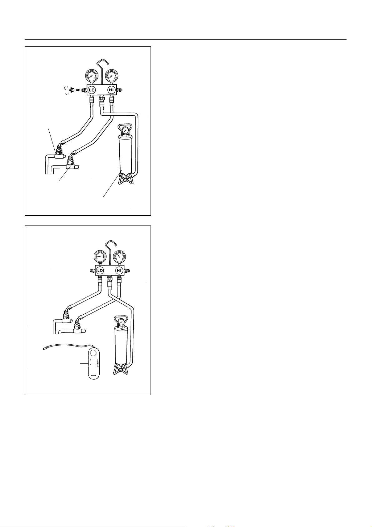
CHARGING
1. INSTALL CHARGING CYLINDER
HINT:
When handling the charging cylinder, always follow the directions given in the instruction manual.
(a) Charge proper amount of refrigerant into the charging cyl-
inder.
(b) Connect the center hose to the charging cylinder.
CAUTION:
Do not open both high and low pressure hand valves of
manifold gauge set.
(c) Open the valve of charging cylinder.
(d) Press the valve core on the side of manifold gauge and
expel the air inside of the center hose.
Charging Cylinder
N13793
Gas Leak
Detector
N13792
2. INSPECT REFRIGERATION SYSTEM FOR LEAKS
(a) Open the high pressure hand valve and charge refriger-
ant.
(b) When the low pressure gauge indicates 98 kPa
2
(1 kgf/cm
, 14 psi), close the high pressure hand valve.
(c) Using a gas leak detector, check the system for leakage.
(d) If leak is found, repair the faulty component or connection.
CAUTION:
Use the refrigerant recovery/ recycling machine to recover
the refrigerant whenever replacing parts.
1997 LEXUS ES300 (RM511U)
1568Author: Date:
Page 12
AC–12
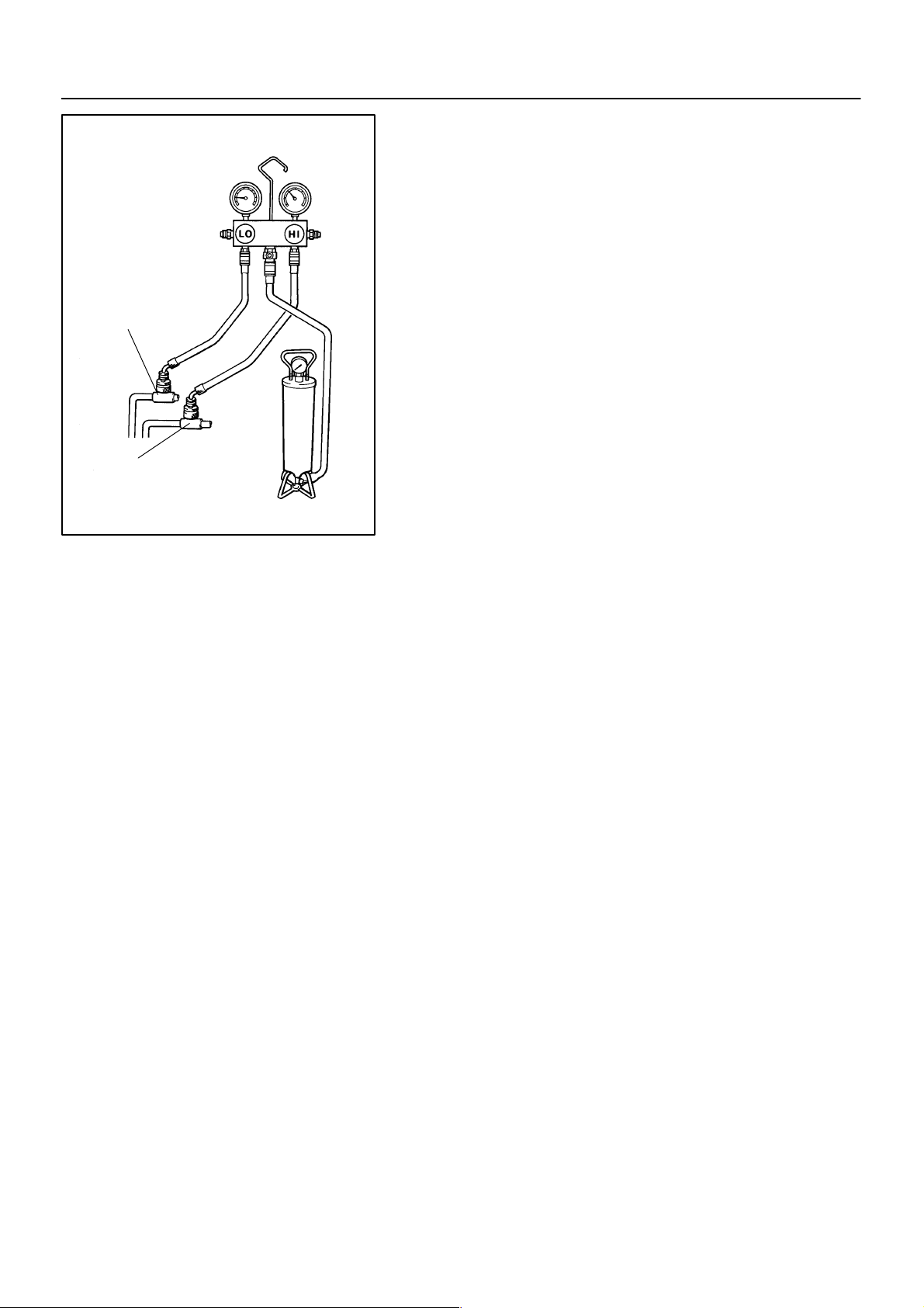
Low Pressure
Service Valve
High Pressure
Service Valve
N13790
–AIR CONDITIONING AIR CONDITIONING SYSTEM
3. CHARGE REFRIGERANT INTO REFRIGERANT SYS-
TEM
If there is no leak after refrigerant leak check, charge the proper
amount of refrigerant into refrigeration system.
CAUTION:
Never run the engine when charging system through
the high pressure side.
Do not open the low pressure hand valve when the
system is being charged with liquid refrigerant.
(a) Open the high pressure and valve fully.
(b) Charge specified amount of refrigerant, then close the
high pressure hand valve.
HINT:
A fully charged system is indicated by the sight glass being free
of any bubbles.
4. SET OFF MANIFOLD GAUGE SET
(a) Close both hand valves of manifold gauge set.
(b) Disconnect the quick disconnect adapters from the ser-
vice valve.
5. INSTALL CAPS TO SERVICE VALVES ON REFRIGER-
ANT LINES
1997 LEXUS ES300 (RM511U)
1569Author: Date:
Page 13
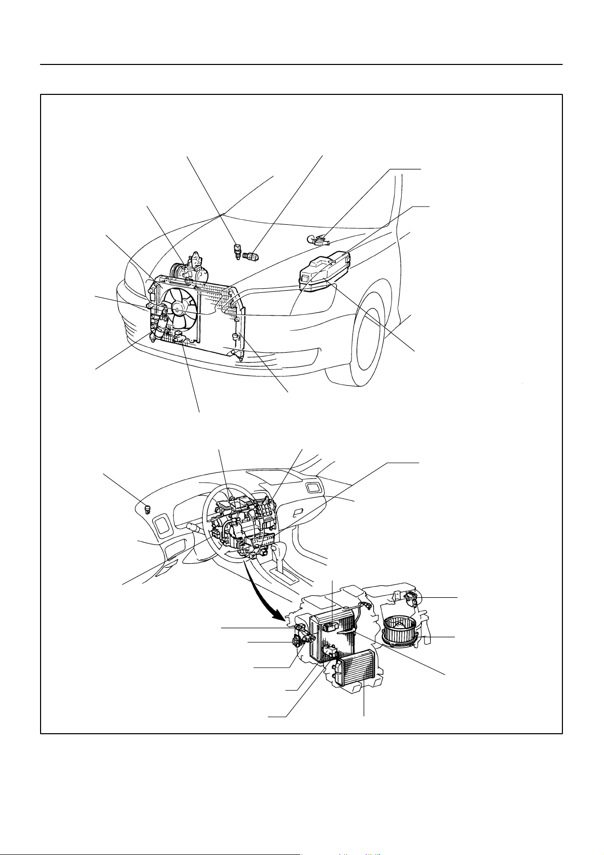
LOCATION
No. 1 Engine Coolant Temperature
(ECT) Switch
AC–13
–AIR CONDITIONING AIR CONDITIONING SYSTEM
No. 2 Engine Coolant Temperature
(ECT) Switch
Water Valve
Compressor
Condenser Fan
Pressure
Switch
Receiver
Solar Sensor
Ambient Temperature Sensor
A/C Unit
Condenser
Blower Unit
Engine Room Relay
Block No. 1
Heater Main Relay
(Marking: HTR RLY)
Magnetic Clutch Relay
(Marking: MG CLT RLY)
No. 2 Cooling Fan Relay
(Marking: FAN RLY NO.2)
No. 3 Cooling Fan Relay
(Marking: FAN RLY NO.3)
Engine Room Junction
Block No. 2
Engine Main Relay
(Marking: ENGINE MAIN RLY)
No. 1 Cooling Fan Relay
(Marking: FAN RLY NO.1)
A/C Control Assembly
A/C Control Panel
A/C Amplifier
Room Temperature Sensor
Blower Resistor
Blower Motor Linear Controller
1997 LEXUS ES300 (RM511U)
Air Outlet Servomotor
Air Mix Servomotor
Evaporator
Expansion Valve
Heater Radiator
Air Inlet Servomotor
Blower Motor
Evaporator Temperature Sensor
Z19363
1570Author: Date:
AC09G–03
Page 14
AC–14
–AIR CONDITIONING DRIVE BELT
Correct
Crankshaft Pulley
DENSO
Wrong
Generator
Compressor
Borroughs
CH0086
N17028
DRIVE BELT
AC09H–01
ON–VEHICLE INSPECTION
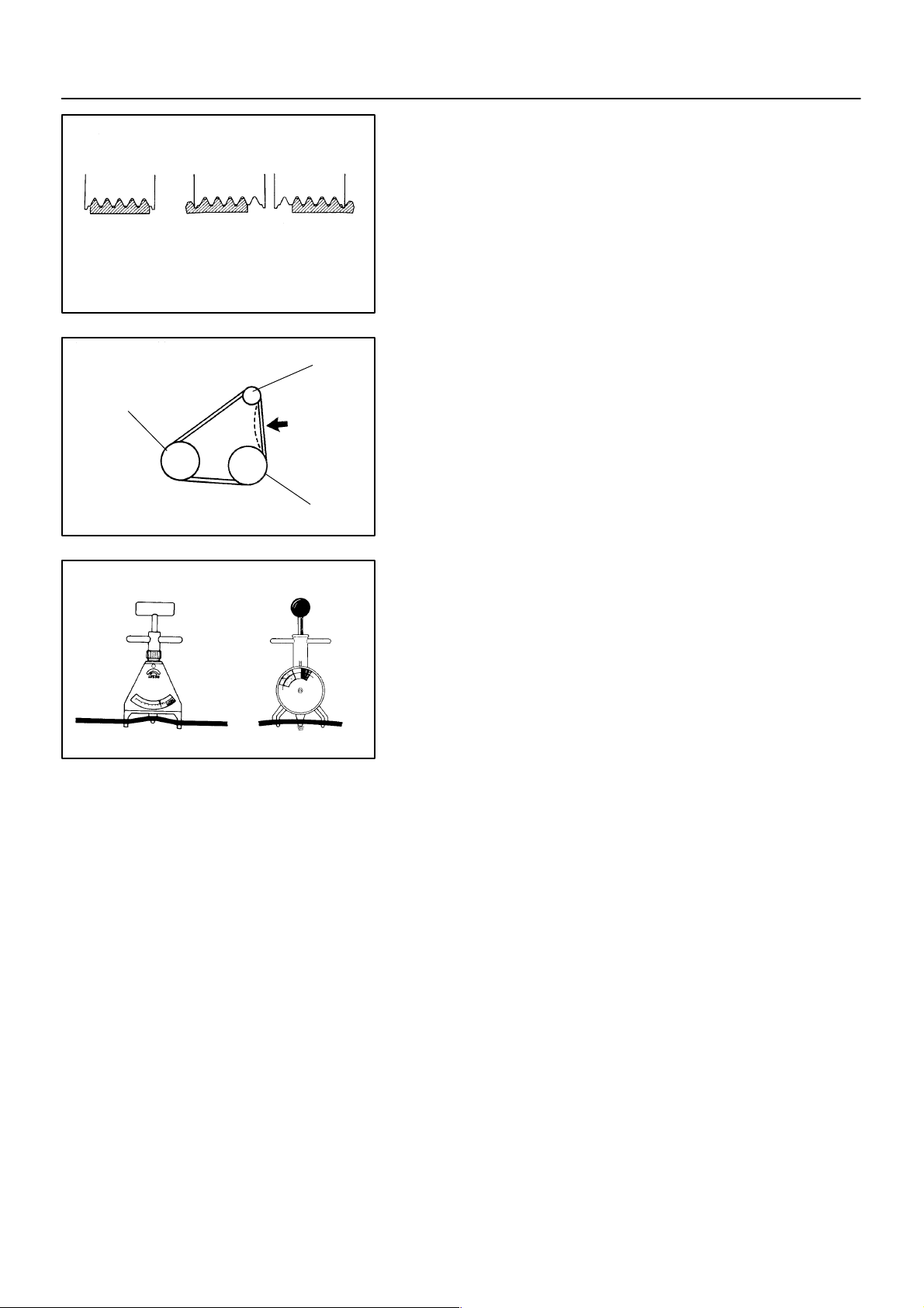
1. INSPECT DRIVE BELT’S INSTALLATION CONDITION
Check that the drive belt fits properly in the ribbed grooves.
2. INSPECT DRIVE BELT TENSION
Using a belt tension gauge, check the drive belt tension.
Drive belt tension:
New belt: 165 ± 26 lbf
Used belt: 110 ± 11 lbf
HINT:
”New belt” refers to a belt which has been used less than
5 minutes on a running engine.
”Used belt” refers to a belt which has been used on a run-
ning engine for 5 minutes or more.
After installing the drive belt, check that it fits properly in
the ribbed grooves.
N01881
1997 LEXUS ES300 (RM511U)
1571Author: Date:
Page 15
Adjusting
Lock Bolt
Pivot Bolt
Adjusting Bolt
P19938
AC–15
–AIR CONDITIONING DRIVE BELT
AC09I–01
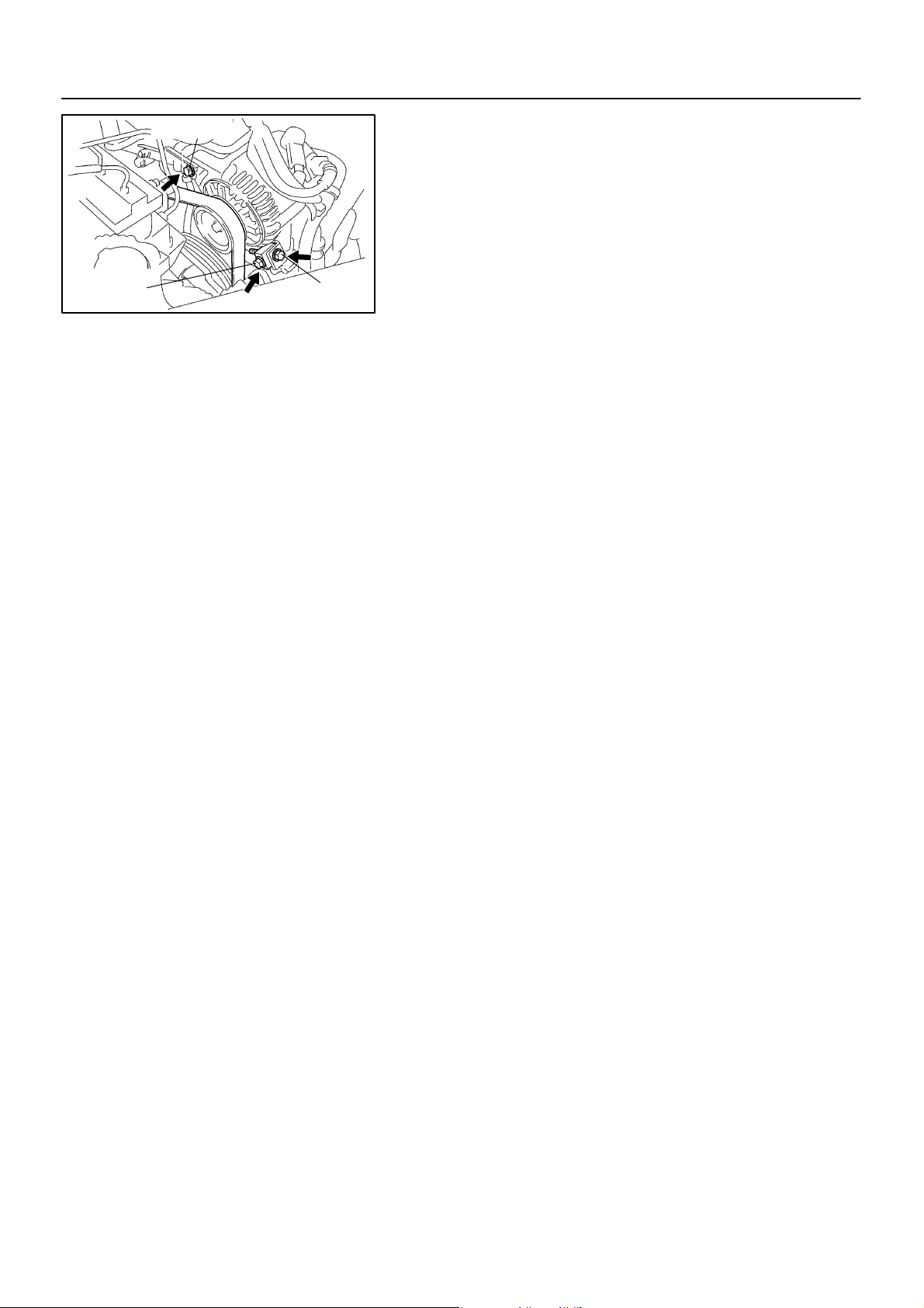
REMOVAL
REMOVE DRIVE BELT
(a) Loosen the pivot bolt and adjusting lock bolt.
Torque:
Pivot bolt: 56 N·m (570 kgf·cm, 41 ft·lbf)
Adjusting lock bolt: 18 N·m (185 kgf·cm, 13 ft·lbf)
(b) Loosen the belt tension by adjusting bolt and remove the
drive belt.
1997 LEXUS ES300 (RM511U)
1572Author: Date:
Page 16

AC–16
–AIR CONDITIONING DRIVE BELT
INSTALLATION
Installation is in the reverse order of removal (See page AC–14 ).
AC09J–02
1997 LEXUS ES300 (RM511U)
1573Author: Date:
Page 17
–AIR CONDITIONING MANIFOLD GAUGE SET
AC–17
Low Pressure
Charging Hose
Sleeve
High Pressure
Charging Hose
N21127
MANIFOLD GAUGE SET
AC09K–01
SET ON
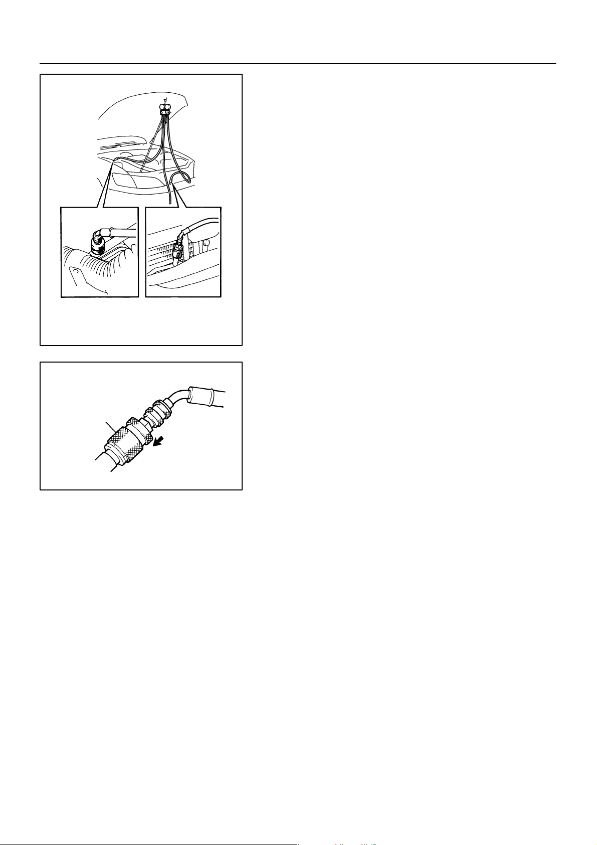
1. CONNECT CHARGING HOSES TO MANIFOLD
GAUGE SET
Tighten the nuts by hand.
CAUTION:
Do not connect the wrong hoses.
2. CONNECT QUICK DISCONNECT ADAPTERS TO
CHARGING HOSES
Tighten the nuts by hand.
3. CLOSE BOTH HAND VALVES OF MANIFOLD GAUGE
SET
4. REMOVE CAPS FROM SERVICE VALVES ON RE-
FRIGERANT LINE
5. CONNECT QUICK DISCONNECT ADAPTERS TO SER-
VICE VALVES
HINT:
Push the quick disconnect adapter onto the service valve, then
slide the sleeve of the quick disconnect adapter downward to
lock it.
N04392
1997 LEXUS ES300 (RM511U)
1574Author: Date:
Page 18
AC–18
N06553
–AIR CONDITIONING MANIFOLD GAUGE SET
AC09L–01
SET OFF
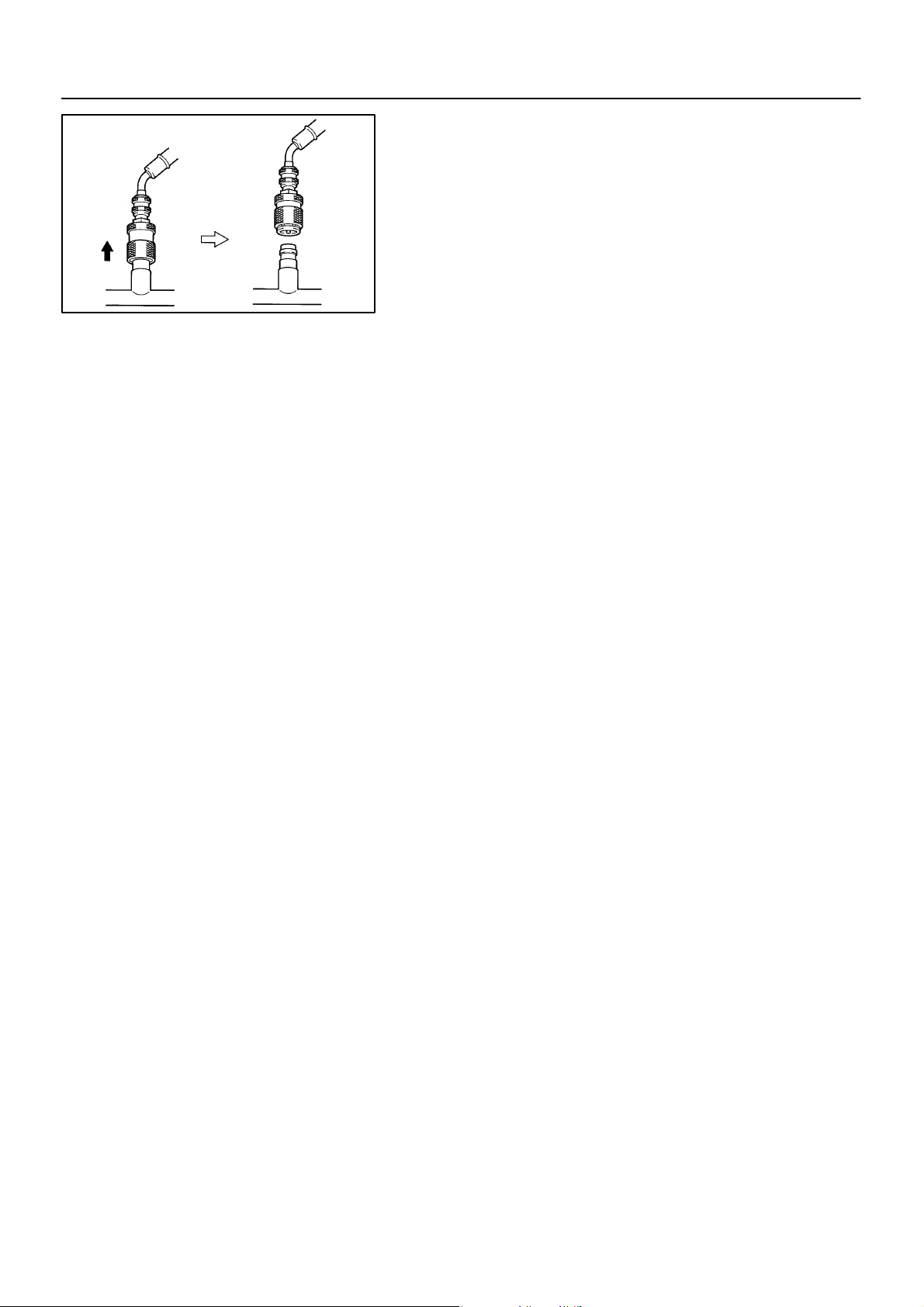
1. CLOSE BOTH HAND VALVES OF MANIFOLD GAUGE
SET
2. DISCONNECT QUICK DISCONNECT ADAPTERS
FROM SERVICE VALVES ON REFRIGERANT LINE
HINT:
Slide the sleeve of the quick disconnect adapter upward to unlock the adapter and remove it from the service valve.
3. INSTALL CAPS TO SERVICE VALVES ON REFRIGER-
ANT LINE
1997 LEXUS ES300 (RM511U)
1575Author: Date:
Page 19

–AIR CONDITIONING REFRIGERANT LINE
REFRIGERANT LINE
ON–VEHICLE INSPECTION
1. INSPECTION HOSE AND TUBE CONNECTIONS FOR LOOSENESS
2. INSPECT HOSES AND TUBES FOR LEAKAGE
Using a gas leak detector, check for leakage of refrigerant.
AC–19
AC09M–01
1997 LEXUS ES300 (RM511U)
1576Author: Date:
Page 20
AC–20
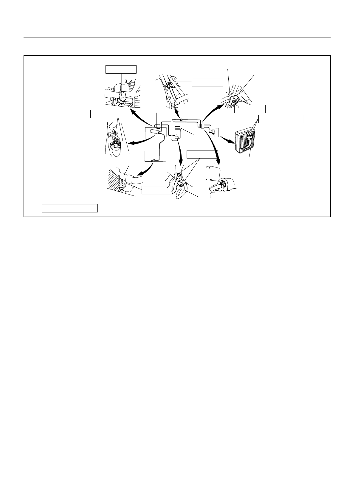
LOCATION
–AIR CONDITIONING REFRIGERANT LINE
AC09N–02
22 (225, 16)
Discharge Hose
5.4 (55, 48 in.·lbf)
Condenser
Liquid Tube
N·m (kgf·cm, ft·lbf) : Specified torque
Suction
Hose
Receiver
Discharge
Hose
14 (140, 10)
Suction Tube
32 (330, 24)
Compressor
10 (100, 7)
Suction Hose
Suction Tube
10 (100, 7)
Evaporator
Expansion Valve
Liquid Tube
5.4 (55, 48 in.·lbf)
10 (100, 7)
N21108
1997 LEXUS ES300 (RM511U)
1577Author: Date:
Page 21
–AIR CONDITIONING REFRIGERANT LINE
REPLACEMENT
1. DISCHARGE REFRIGERANT FROM REFRIGERATION SYSTEM
2. REPLACE FAULTY TUBE OR HOSE
NOTICE:
Cap the open fittings immediately to keep moisture or dirt out of the system.
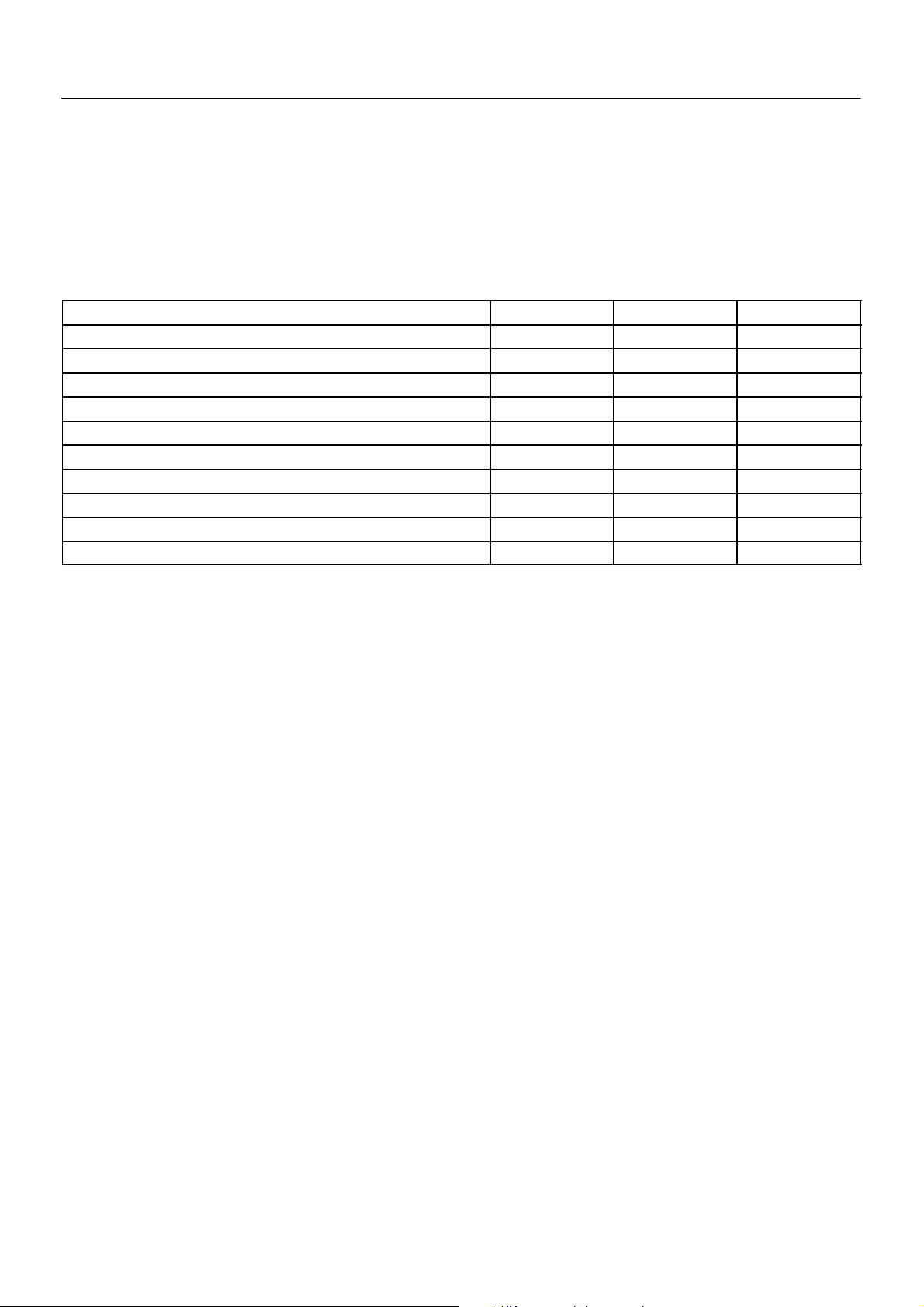
3. TIGHTEN JOINT OF BOLT OR NUT TO SPECIFIED TORQUE
NOTICE:
Connections should not be torqued tighter than the specified torqued.
Part tightened N·m kgf·cm ft·lbf
Receiver x Liquid tube 5.4 55 48 in.·lbf
Condenser x Discharge hose 22 225 16
Condenser x Liquid tube 14 140 10
Compressor x Discharge hose 10 100 7
Compressor x Suction hose 10 100 7
A/C unit x Liquid and Suction tube 10 100 7
Evaporator x Expansion valve 5.4 55 48 in.·lbf
Liquid line (Block joint) 10 100 7
Suction line (Block joint) 10 100 7
Suction line (Piping joint) 32 330 24
4. EVACUATE AIR IN REFRIGERATION SYSTEM AND CHARGE WITH REFRIGERANT
Specified amount: 800 ± 50 g (28.22 ± 1.76 oz.)
5. INSPECT FOR LEAKAGE OF REFRIGERANT
Using a gas leak detector, check for leakage of refrigerant.
6. INSPECT AIR CONDITIONING OPERATION
AC–21
AC09O–02
1997 LEXUS ES300 (RM511U)
1578Author: Date:
Page 22
AC–22
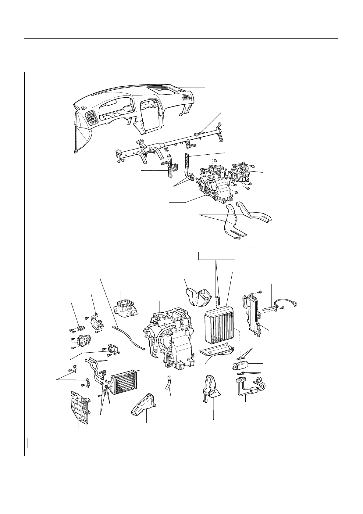
AIR CONDITIONING UNIT
COMPONENTS
–AIR CONDITIONING AIR CONDITIONING UNIT
AC09P–03
Instrument Panel
Reinforcement
No. 2 Brace
Water Valve Control
Cable
Air Outlet Servomotor
Blower Resistor
Blower Motor
Linear
Controller
No. 1 Brace
Water Hose
A/C Unit
Side Air Duct LH
A/C Unit Case
Rear Heater Duct
Side Air Duct RH
5.4 (55, 48)
Evaporator
Blower Unit
Evaporator Temperature
Sensor
X7
Evaporator Cover
O–Ring
Air Mix Servomotor
Clamp
Heater Protector
N·m (kgf·cm, in.·lbf)
: Specified torque
Non–reusable part
1997 LEXUS ES300 (RM511U)
Heater Radiator
Pipe
O–Ring
Clamp
Heater
Radiator
Drain Hose
Foot Air Duct LH
Insulator
Liquid and Suction Tube
Foot Air Duct RH
Expansion Valve
O–Ring
Z19364
1579Author: Date:
Page 23
AC–23
–AIR CONDITIONING AIR CONDITIONING UNIT
AC09Q–01
REMOVAL
1. DISCHARGE REFRIGERANT FROM REFRIGERATION
SYSTEM
HINT:
At the time of the installation, please refer to the following item.
Evacuate air from refrigeration system.
Charge system with refrigerant and inspect for leakage of refrigerant.
Specified amount: 800 ± 50 g (28.22 ± 1.76 oz.)
2. DRAIN ENGINE COOLANT FROM RADIATOR
HINT:
It is not necessary to drain out all the coolant.
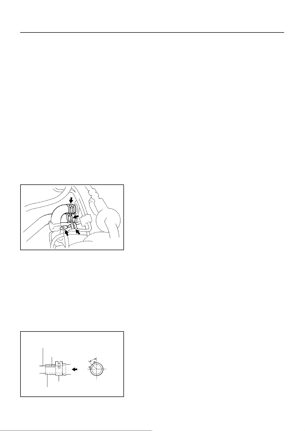
Heater Radiator Pipe
Marking
45 ± 10°
RH
Upper
N21067
LH
3. DISCONNECT WATER VALVE CONTROL CABLE
FROM WATER VALVE
HINT:
At the in time of the installation, please refer to the following
item.
For installing the control cable, refer to ”INSTALLATION” of
”WATER VALVE” on page AC–60 .
4. DISCONNECT WATER HOSES FROM HEATER RADIATOR PIPES
(a) Using pliers, grip the claw of the hose clip and slide the
hose clip along the hose.
(b) Disconnect the water hoses.
HINT:
At the time of the installation, please refer to the following items.
Push the water hose onto the heater radiator pipe as far
as the pipe grommet and install the hose clip.
Install the hose clip in a position, as shown in the illustra-
tion.
Hose Clip
Water Hose
1997 LEXUS ES300 (RM511U)
Lower
N20237
1580Author: Date:
Page 24
AC–24
N21063
–AIR CONDITIONING AIR CONDITIONING UNIT
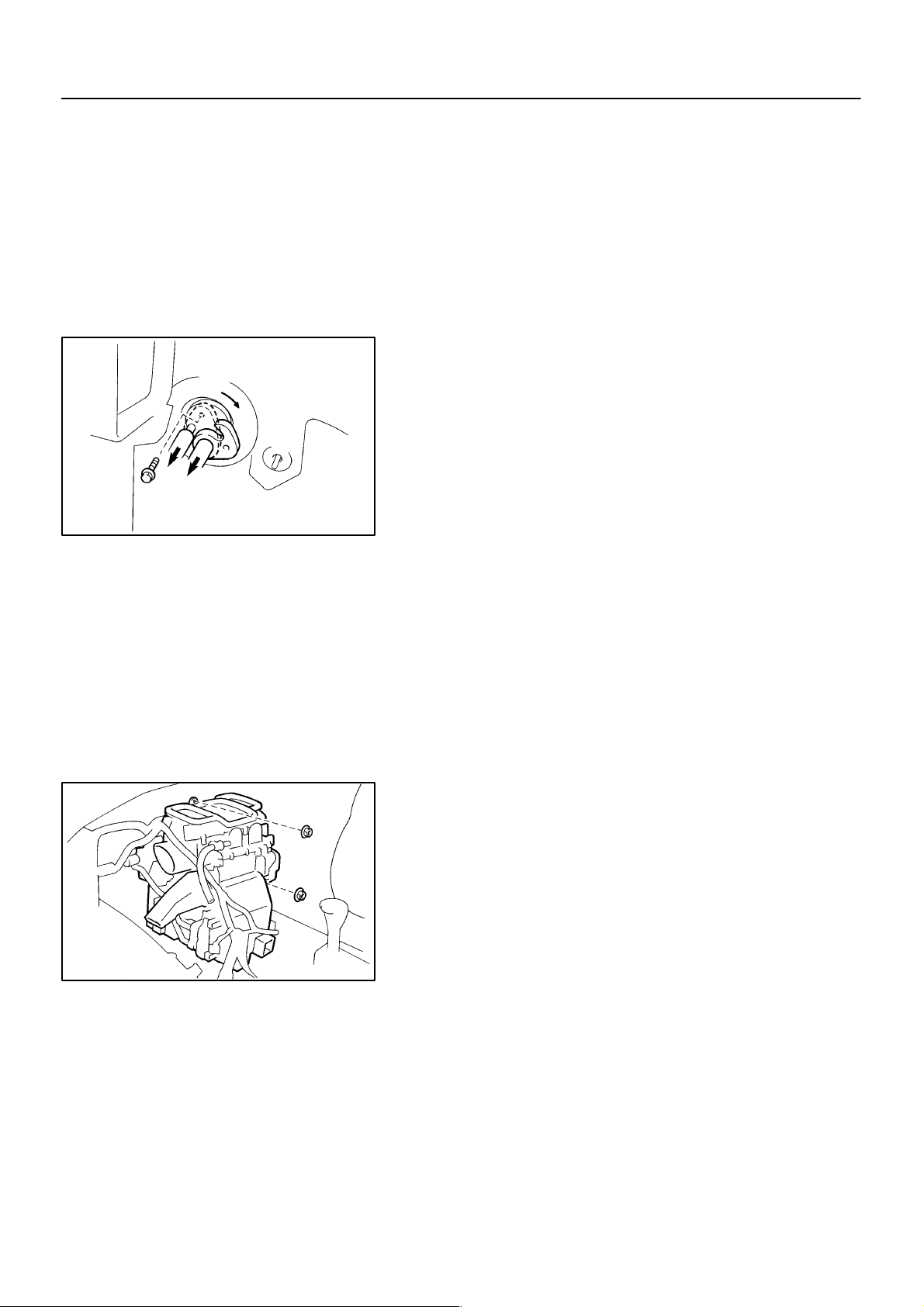
5. REMOVE THESE PARTS:
(a) Blower unit (See page AC–29)
(b) Instrument panel and reinforcement (See page BO–82)
6. DISCONNECT LIQUID AND SUCTION TUBES
Remove the bolt and slide the plate, then disconnect both
tubes.
Torque: 10 N·m (100 kgf·cm, 7 ft·lbf)
NOTICE:
Cap the open fittings immediately to keep moisture or dirt
out of the system.
HINT:
At the time of the installation, please refer to the following item.
Lubricate 2 new O–rings with compressor oil and install the
tubes.
1997 LEXUS ES300 (RM511U)
7. REMOVE A/C UNIT
(a) Slide the floor carpet backward.
(b) Remove the rear heater ducts.
(c) Disconnect the connectors.
(d) Remove the 2 nuts and A/C unit.
N21065
1581Author: Date:
Page 25

–AIR CONDITIONING AIR CONDITIONING UNIT
DISASSEMBLY
1. REMOVE THESE PARTS:
(a) Side air ducts LH, RH
(b) Foot air ducts LH, RH
2. REMOVE EVAPORATOR TEMP. SENSOR
Remove the screw and pull out the sensor.
3. REMOVE EVAPORATOR
(a) Remove the 6 screws and evaporator cover.
HINT:
At the time of reassembly, please refer to the following item.
Do not reuse the evaporator cover.
(b) Pull out the evaporator.
HINT:
At the time of reassembly, please refer to the following item.
If evaporator is replaced, add compressor oil to evaporator.
Add 40 cc (1.4 fl.oz.)
Compressor oil: ND–OIL 8 or equivalent
4. REMOVE EXPANSION VALVE
Using a hexagon wrench, remove the 2 bolts and separate the evaporator and expansion valve.
Torque: 5.4 N·m (55 kgf·cm, 48 in.·lbf)
HINT:
At the time of reassembly, please refer to the following item.
Lubricate 4 new O–rings with compressor oil and install the valve.
5. REMOVE AIR MIX SERVOMOTOR
(a) Remove the 3 screws and servomotor.
(b) Remove the water valve control cable from the servomotor.
6. REMOVE AIR OUTLET SERVOMOTOR
Remove the 2 screws and servomotor.
7. REMOVE HEATER RADIATOR
(a) Release the 3 claws and remove the heater protector.
(b) Remove the 2 screws and 2 clamps, then pull out the heater radiator.
(c) Remove the 2 screws, 2 clamps and heater radiator pipes from the heater radiator.
8. REMOVE BLOWER RESISTOR
(a) Disconnect the connector.
(b) Remove the 2 screws and blower resistor.
9. REMOVE BLOWER MOTOR LINEAR CONTROLLER
(a) Disconnect the connector.
(b) Remove the 2 screws and blower motor linear controller.
10. REMOVE WIRE HARNESS
Release the claw and remove the wire harness.
AC–25
AC09R–01
1997 LEXUS ES300 (RM511U)
1582Author: Date:
Page 26

AC–26
–AIR CONDITIONING AIR CONDITIONING UNIT
REASSEMBLY
Reassembly is in the reverse order of disassembly (See page AC–25 ).
AC09T–01
1997 LEXUS ES300 (RM511U)
1583Author: Date:
Page 27

–AIR CONDITIONING AIR CONDITIONING UNIT
INSTALLATION
Installation is in the reverse order of removal (See page AC–23 ).
AC–27
AC09S–01
1997 LEXUS ES300 (RM511U)
1584Author: Date:
Page 28
AC–28
BLOWER UNIT
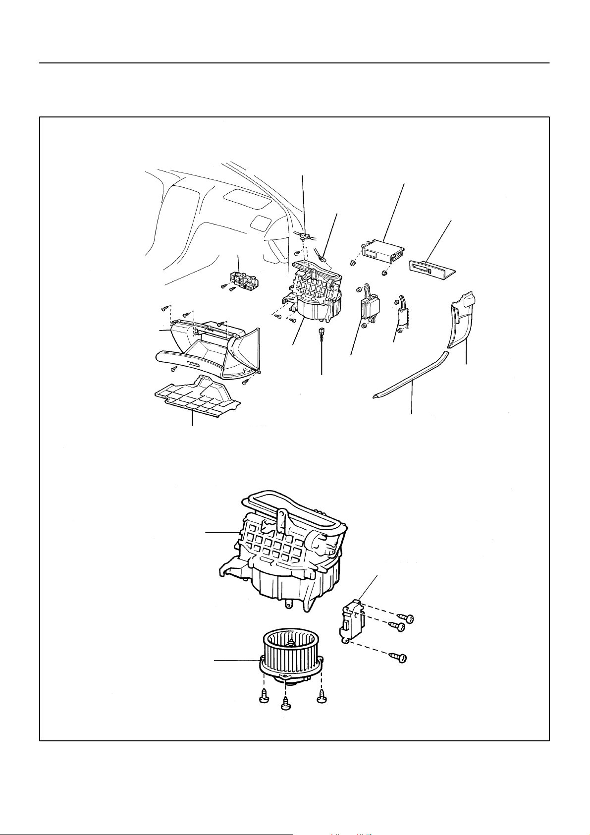
COMPONENTS
–AIR CONDITIONING BLOWER UNIT
AC09U–02
Glove Compertment
Evaporator Temp. Sensor
Connector
Connector Bracket
Blower Unit
Blower Motor Connector
No. 2 Instrument Panel Under Cover
w/ CD Changer:
CD Changer Assembly
Air Inlet Servomotor
Connector
Audio Amplifier
ECM
Front Door Scuff Plate RH
w/ CD Changer:
Finish Upper Panel
Cowl Side Trim RH
Blower Unit Case
1997 LEXUS ES300 (RM511U)
Air Inlet Servomotor
Blower Motor
Z19365
1585Author: Date:
Page 29

–AIR CONDITIONING BLOWER UNIT
REMOVAL
1. REMOVE THESE PARTS:
(a) Cowl side trim RH
(b) Front door scuff plate RH
(c) No.2 instrument panel under cover
(d) Glove Compartment
(e) w/ CD Changer:
Finish upper panel
(f) w/ CD Changer:
CD change assembly
(g) Audio amplifier
(h) ECM
2. REMOVE CONNECTOR BRACKET SET SCREWS
3. REMOVE BLOWER UNIT
(a) Disconnect the connectors from blower unit.
(b) Disconnect the wire harness clamps.
(c) Disconnect the evaporator temp. sensor connector clamp.
(d) Remove the 2 screws, bolt and nut, then remove the blower unit.
AC–29
AC09V–02
1997 LEXUS ES300 (RM511U)
1586Author: Date:
Page 30

AC–30
DISASSEMBLY
1. REMOVE BLOWER MOTOR
Remove the 3 screws and blower motor.
2. REMOVE AIR INLET SERVOMOTOR
Remove the 3 screws and servomotor.
–AIR CONDITIONING BLOWER UNIT
AC09W–01
1997 LEXUS ES300 (RM511U)
1587Author: Date:
Page 31

–AIR CONDITIONING BLOWER UNIT
REASSEMBLY
Reassembly is in the reverse order of disassembly (See page AC–30 ).
AC–31
AC09X–02
1997 LEXUS ES300 (RM511U)
1588Author: Date:
Page 32

AC–32
–AIR CONDITIONING BLOWER UNIT
INSTALLATION
Installation is in the reverse order of removal (See page AC–29 ).
AC09Y–02
1997 LEXUS ES300 (RM511U)
1589Author: Date:
Page 33
–AIR CONDITIONING COMPRESSOR AND MAGNETIC CLUTCH
COMPRESSOR AND MAGNETIC
AC–33
CLUTCH
AC09Z–01
ON–VEHICLE INSPECTION
1. INSPECT COMPRESSOR FOR METALLIC SOUND
(a) Start the engine.
(b) Check if there is metallic sound from the compressor
when the A/C switch is on.
If metallic sound is heard, replace the compressor assembly.
2. INSPECT REFRIGERANT PRESSURE
(See page AC–3)
3. INSPECT VISUALLY FOR LEAKAGE OF REFRIGERANT FROM SAFETY SEAL
Using a gas leak detector, check for leakage of refrigerant.
If there is any leakage, replace the compressor assembly.
4. INSPECT COMPRESSOR LOCK SENSOR
(See page DI–552)
5. MAKE THESE VISUAL CHECKS:
(a) Leakage of grease from the clutch bearing.
(b) Signs of oil on the pressure plate or rotor.
If necessary, repair or replace.
6. INSPECT MAGNETIC CLUTCH BEARING FOR NOISE
(a) Start the engine.
(b) Check for abnormal noise from near the compressor
when the A/C switch is OFF.
If abnormal noise is being emitted, replace the magnetic clutch.
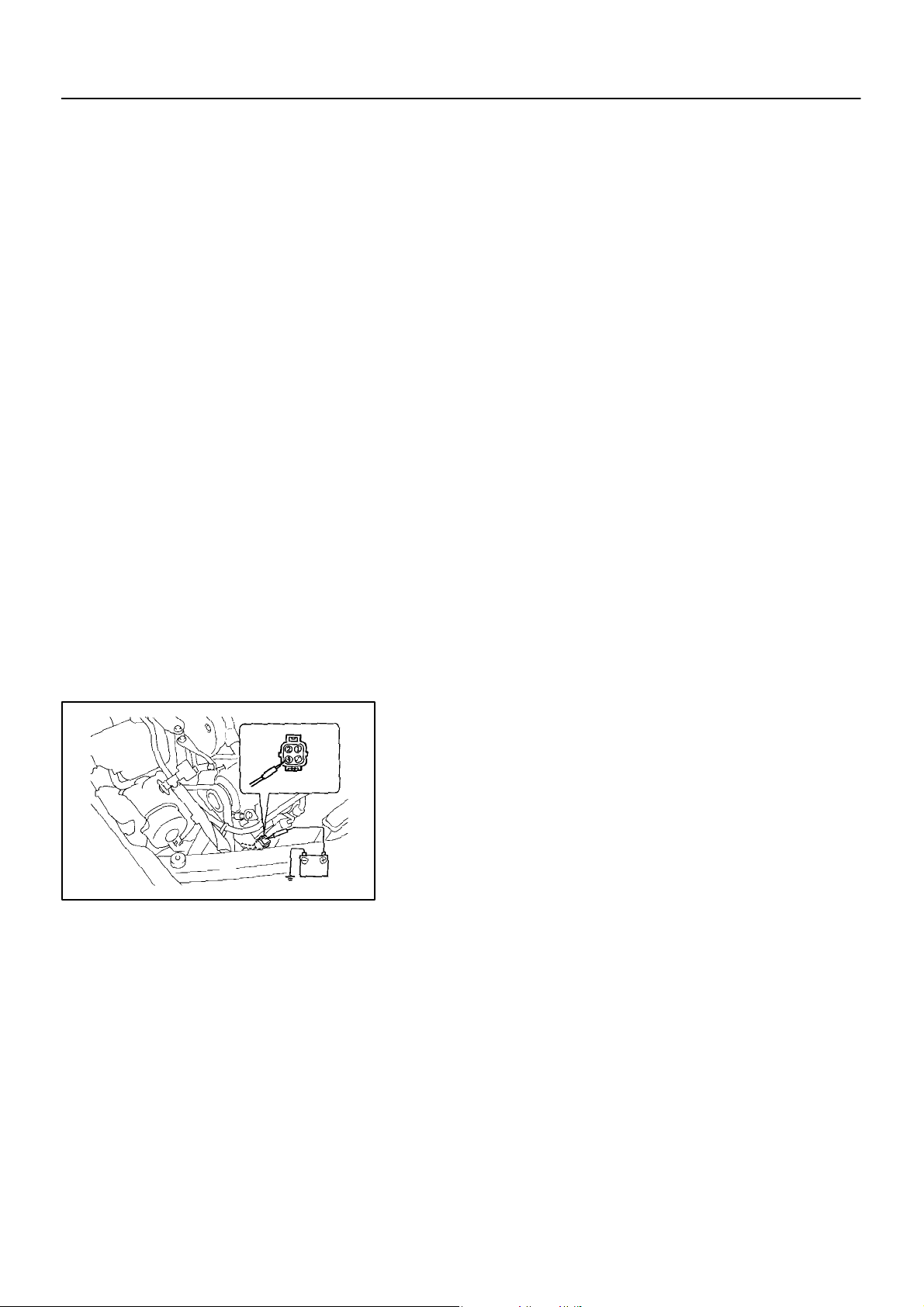
7. INSPECT MAGNETIC CLUTCH
(a) Disconnect the connector from the magnetic clutch.
(b) Connect the positive (+) lead from the battery to the termi-
nal 4 and the negative (–) lead to the body ground.
(c) Check that the magnetic clutch is energized.
If operation is not as specified, replace the magnetic clutch.
1997 LEXUS ES300 (RM511U)
N01150
1590Author: Date:
Page 34
AC–34
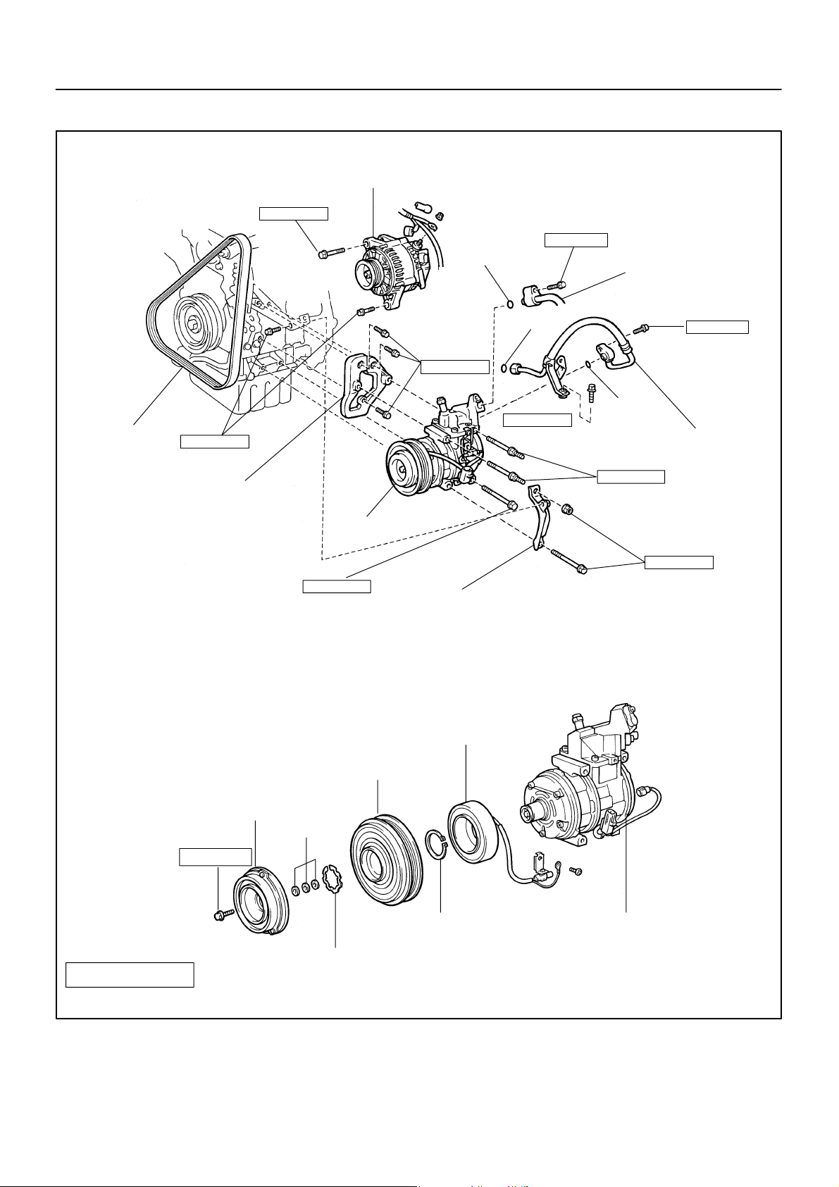
COMPONENTS
–AIR CONDITIONING COMPRESSOR AND MAGNETIC CLUTCH
AC0A0–01
Generator
56 (570, 41)
10 (100, 7)
O–Ring
Discharge Hose
Drive Belt
18 (185, 13)
Compressor Bracket
Compressor
25 (250,18)
O–Ring
25 (250, 18)
32 (330, 24)
Drive Belt Adjusting
Bar Bracket
10 (100, 7)
O–Ring
Suction Hose
25 (250,18)
25 (250,18)
Pressure plate
13.2 (135, 9)
N·m (kgf·cm, ft·lbf) : Specified torque
Non–reusable part
1997 LEXUS ES300 (RM511U)
Shim
Snap Ring
Rotor
Stator
Snap Ring
Compressor
I01448
1591Author: Date:
Page 35
AC–35
–AIR CONDITIONING COMPRESSOR AND MAGNETIC CLUTCH
AC0A1–01
REMOVAL
1. RUN ENGINE AT IDLE SPEED WITH A/C ON FOR
APPROX.10 MINUTES
2. STOP ENGINE
3. DISCONNECT NEGATIVE (–) TERMINAL CABLE
FROM BATTERY
4. DISCHARGE REFRIGERANT FROM REFRIGERATION
SYSTEM
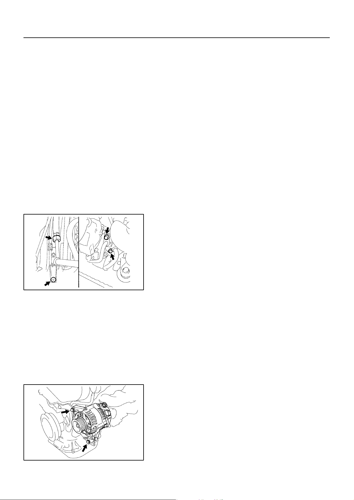
5. REMOVE DRIVE BELT
(See page AC–15)
N20277
6. REMOVE SUCTION HOSE
(a) Remove the suction hose clamping bolt.
(b) Disconnect the wire harness clamp.
(c) Loosen the nut and bolts and remove the suction hose.
NOTICE:
Cap the open fittings immediately to keep moisture or dirt
out of the system.
7. DISCONNECT DISCHARGE HOSE
Remove the bolt and disconnect the hose.
NOTICE:
Cap the open fitting immediately to keep moisture or dirt
out of the system.
8. REMOVE GENERATOR
(a) Disconnect the generator connector.
(b) Remove the nut, and disconnect the generator wire.
(c) Disconnect the wire harness from the clip.
(d) Remove the pivot bolt, plate washer, adjusting lock bolt
and generator.
1997 LEXUS ES300 (RM511U)
P19978
1592Author: Date:
Page 36
AC–36
–AIR CONDITIONING COMPRESSOR AND MAGNETIC CLUTCH
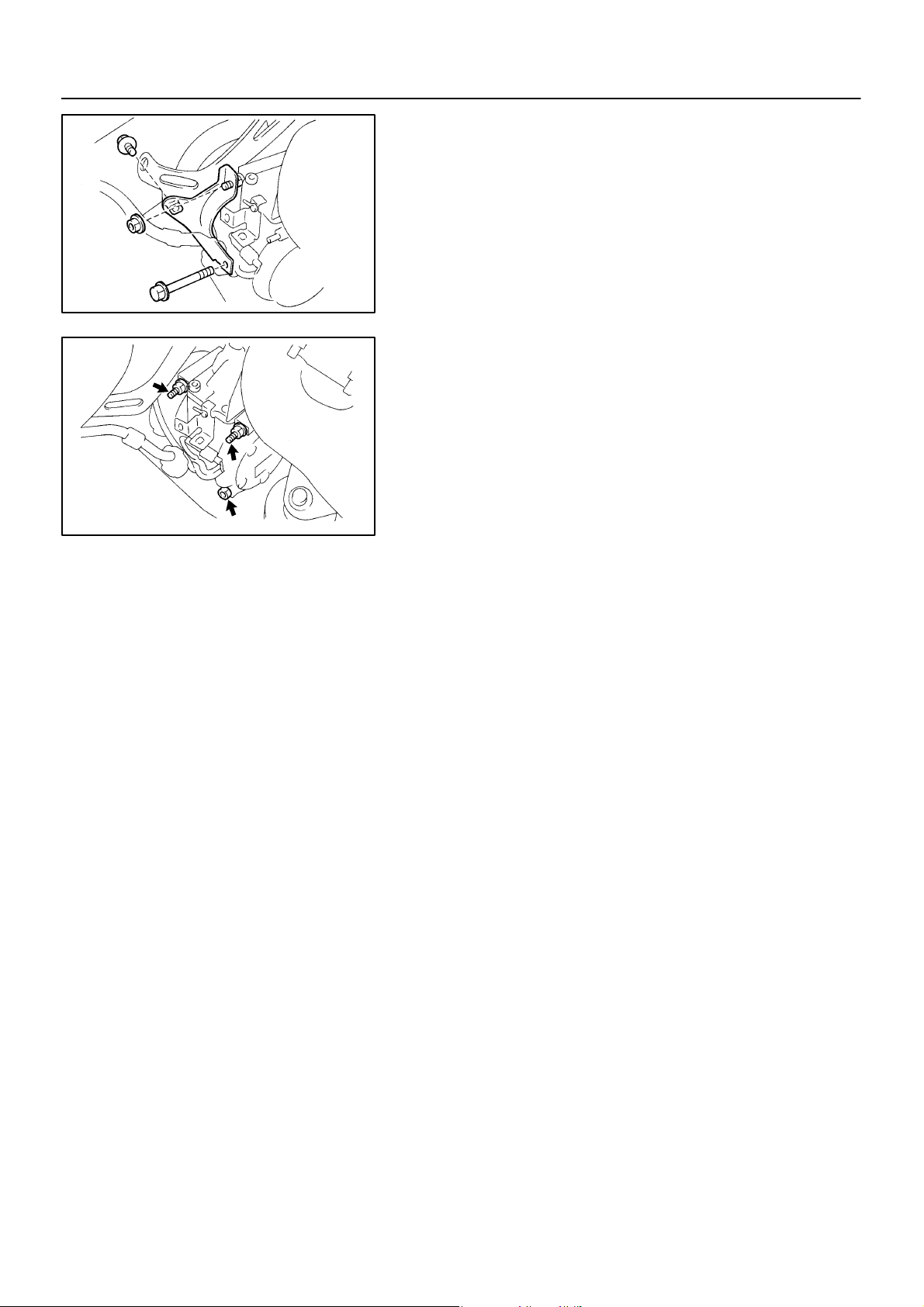
9. REMOVE COMPRESSOR
(a) Disconnect the connector.
(b) Remove the 2 bolts, nut and generator drive belt adjusting
bar bracket.
N20259
(c) Remove the 3 bolts and compressor.
N20241
1997 LEXUS ES300 (RM511U)
1593Author: Date:
Page 37
SST
SST
AC–37
–AIR CONDITIONING COMPRESSOR AND MAGNETIC CLUTCH
AC0A2–03
DISASSEMBLY
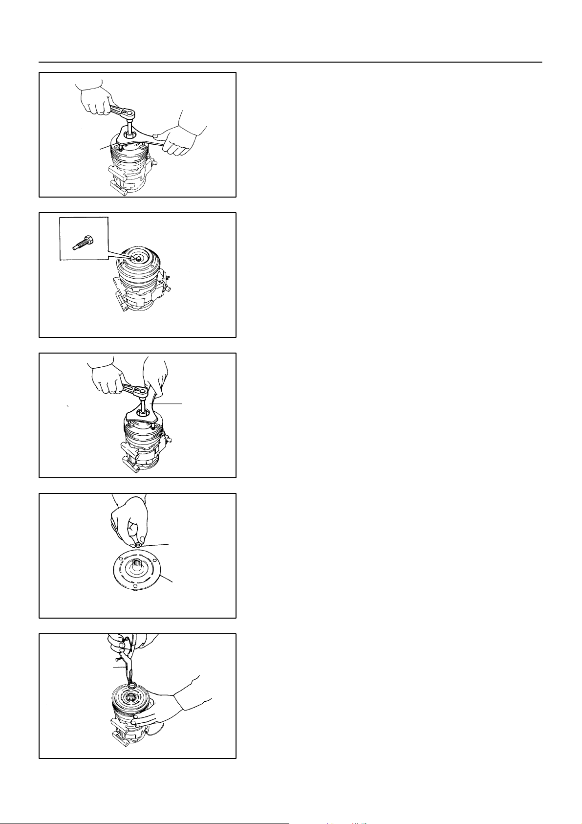
1. REMOVE PRESSURE PLATE
(a) Using SST and a socket wrench, remove the shaft bolt.
Torque: 13.2 N·m (135 kgf·cm, 9 ft·lbf)
SST 07112–76060
AC0943
(b) Install SST on the pressure palate.
SST 07112–66040
SST
Shim
Pressure
Plate
AC0944
(c) Using SST and socket wrench, remove the pressure
plate.
SST 07112–76060
AC0945
(d) Remove the shims from the pressure palate.
AC0946
SST
1997 LEXUS ES300 (RM511U)
2. REMOVE ROTOR
(a) Using SST, remove the snap ring.
SST 07114–84020
AC0947
1594Author: Date:
Page 38
AC–38
R–Shape
Snap Ring
Rotor
–AIR CONDITIONING COMPRESSOR AND MAGNETIC CLUTCH
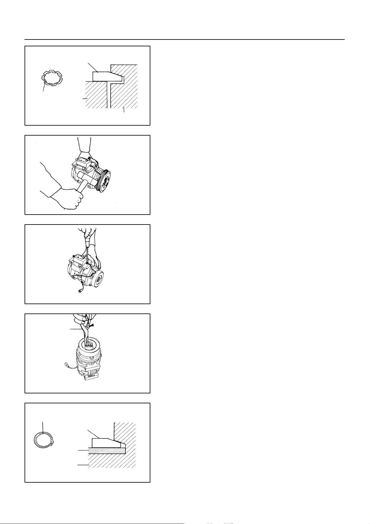
NOTICE:
At the time of reassembly, please refer to the following
item.
The snap ring should be installed so that beveled side
faces up.
Compressor
N20013
(b) Using a plastic hammer, tap the rotor off the shaft.
NOTICE:
Be careful not to damage the pulley when tapping on the rotor.
SST
AC1743
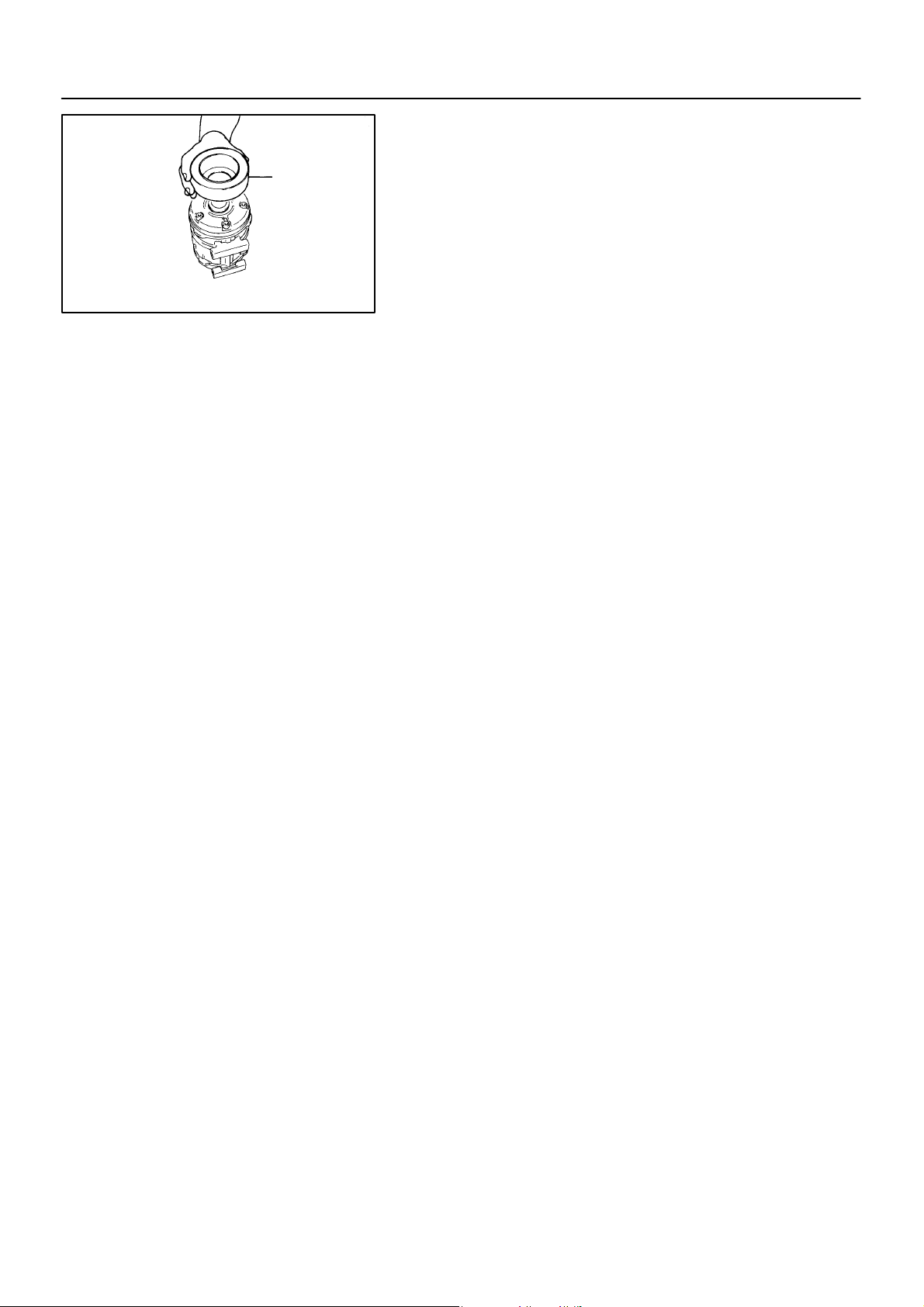
3. REMOVE STATOR
(a) Disconnect the stator lead wire from the compressor
housing.
AC1744
(b) Using SST, remove the snap ring.
SST 07114–84020
AC0950
R–Shape
Snap Ring
Stator
Compressor
1997 LEXUS ES300 (RM511U)
NOTICE:
At the time of reassembly, please refer to the following
item.
The snap ring should be installed so that its beveled side
faces up.
N20012
1595Author: Date:
Page 39
Stator
AC–39
–AIR CONDITIONING COMPRESSOR AND MAGNETIC CLUTCH
(c) Remove the stator.
AC0951
1997 LEXUS ES300 (RM511U)
1596Author: Date:
Page 40
AC–40
Dial Indicator
N04963
–AIR CONDITIONING COMPRESSOR AND MAGNETIC CLUTCH
AC0A3–03
REASSEMBLY
Reassembly is in the reverse order of disassembly (See
page AC–37 ).
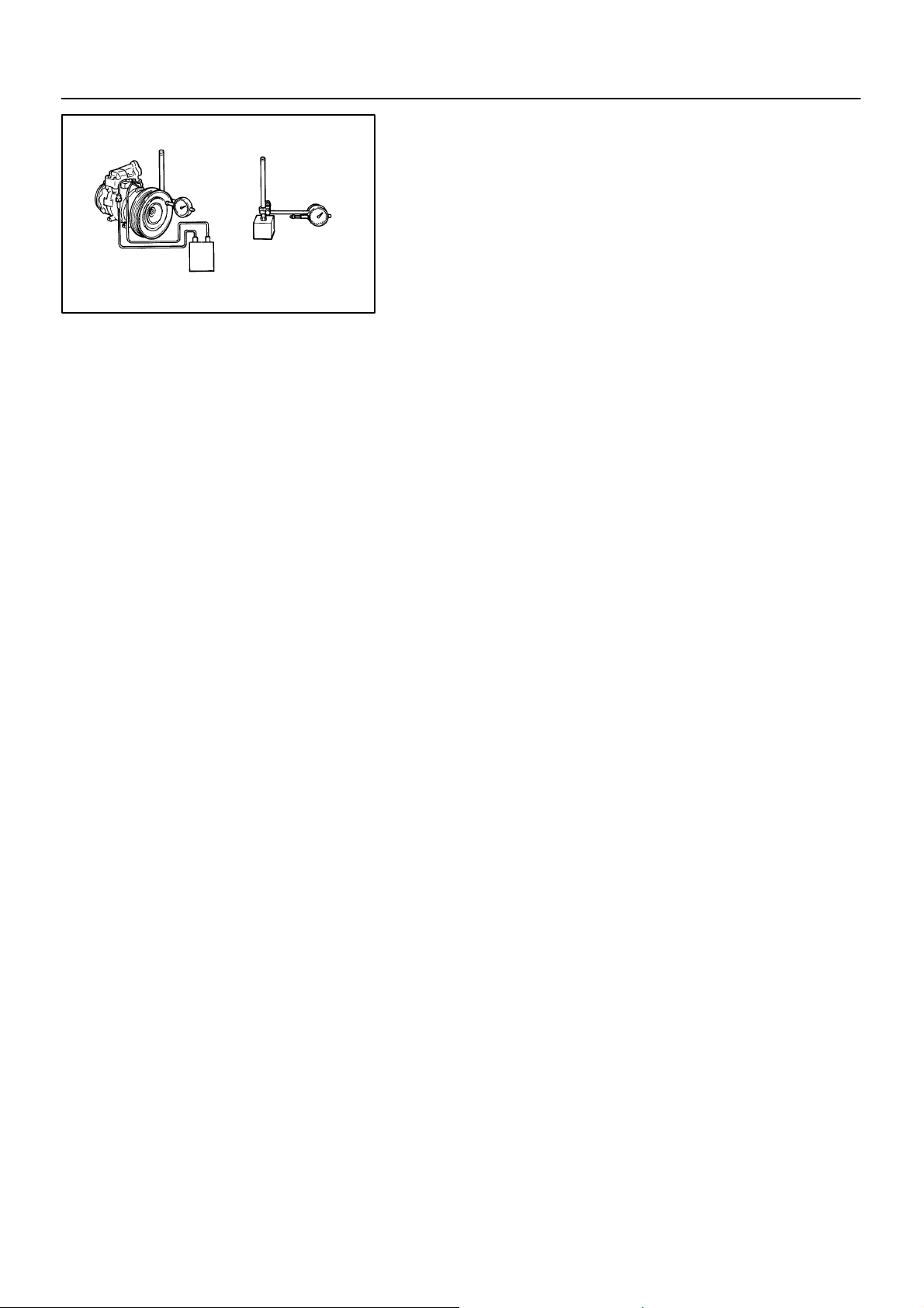
CHECK CLEARANCE OF MAGNETIC CLUTCH
HINT:
After reassembly, check the magnetic clutch clearance.
(a) Set the dial indicator to the pressure plate of the magnetic
clutch.
(b) Connect the magnetic clutch lead wire to the positive (+)
terminal of the battery.
(c) Check the clearance between the pressure plate and ro-
tor when connecting the negative (–) terminal battery.
Standard clearance:
0.5 ± 0.15 mm (0.020 ± 0.0059 in.)
If the clearance is not within the standard clearance, adjust the
clearance using shims to obtain the standard clearance.
Shim thickness:
0.1 mm (0.004 in.)
0.3 mm (0.012 in.)
0.5 mm (0.020in.)
1997 LEXUS ES300 (RM511U)
1597Author: Date:
Page 41
(A)
(B)
N20259
AC–41
–AIR CONDITIONING COMPRESSOR AND MAGNETIC CLUTCH
AC0A4–03
INSTALLATION
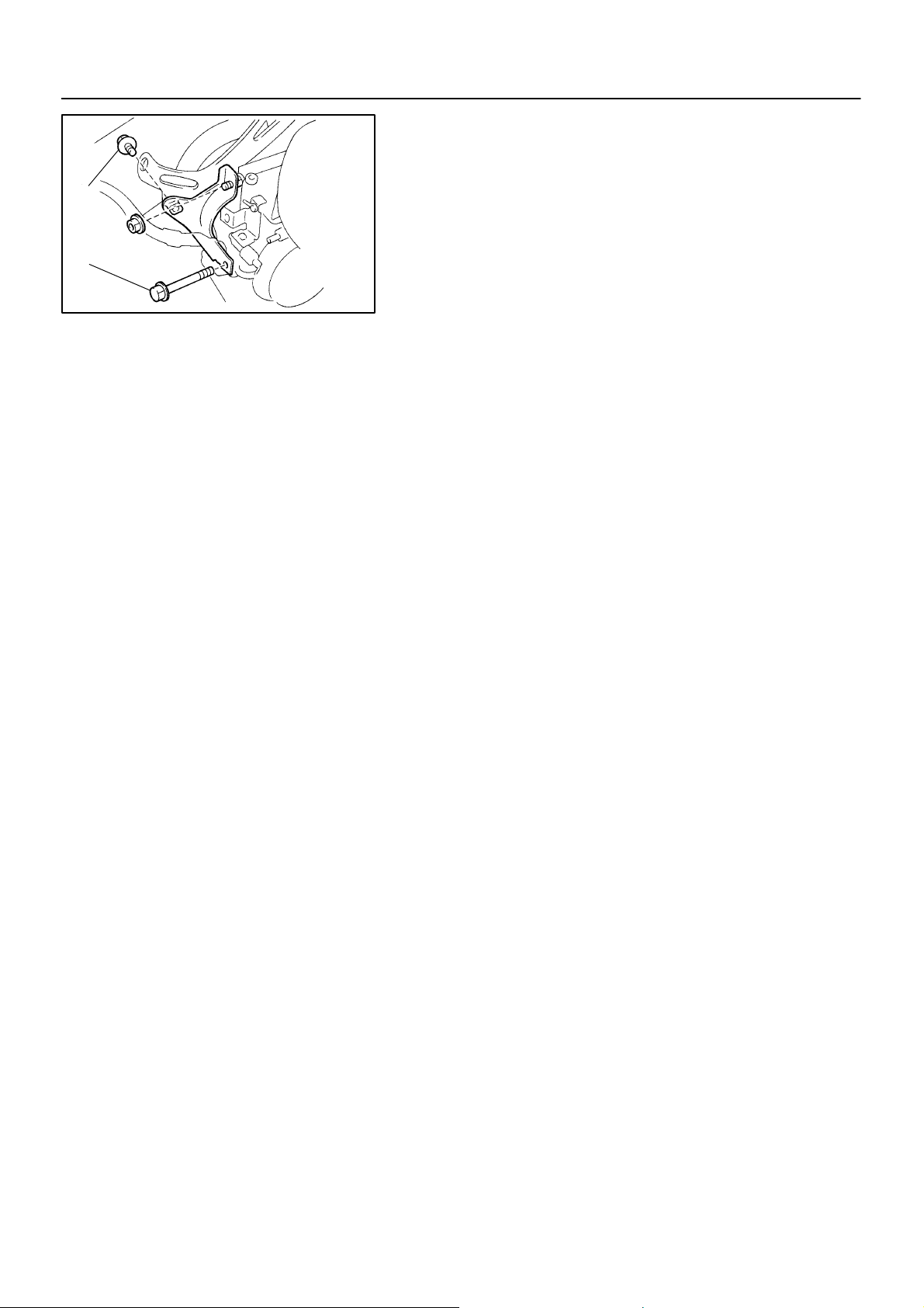
1. INSTALL COMPRESSOR
(a) Install the compressor with 3 bolts.
Torque: 25 N·m (250 kgf·cm, 18 ft·lbf)
(b) Install the generator drive belt adjusting bar bracket with
2 bolts and a nut.
Torque:
Bolt (A): 18 N·m (185 kgf·cm, 13 ft·lbf)
Bolt (B): 25 N·m (250 kgf·cm, 18 ft·lbf)
Nut: 25 N·m (250 kgf·cm, 18 ft·lbf)
2. INSTALL GENERATOR
(a) Mount generator on the generator bracket with the pivot
bolt and adjusting lock bolt. Do not tighten the bolts yet.
(b) Connect the generator connector.
(c) Connect the generator wire with the nut.
3. CONNECT DISCHARGE HOSE
Torque:10 N·m (100 kgf·cm, 7 ft·lbf)
NOTICE:
Hoses should be connected immediately after the caps
have been removed.
HINT:
Lubricate a new O–ring with compressor oil and install the tube.
4. INSTALL SUCTION HOSE
(a) Install the suction hose and tighten the bolt and nut.
Torque:
Piping joint: 32 N·m (330 kgf·cm, 24 ft·lbf)
Block joint: 10 N·m (100 kgf·cm, 7 ft·lbf)
HINT:
Lubricate 2 new O–rings with the compressor oil and install the
hose.
(b) Install the suction hose clamping bolt.
(c) Connect the wire harness clamp.
5. INSTALL DRIVE BELT
(See page AC–16)
6. INSPECT DRIVE BELT
(See page AC–14)
7. CONNECT NEGATIVE (–) TERMINAL CABLE TO B ATTERY
8. EVACUATE AIR IN REFRIGERATION SYSTEM AND
CHARGE WITH REFRIGERANT
Specified amount: 800 ± 50 g (28.22 ± 1.76 oz.)
9. INSPECT FOR LEAKAGE OF REFRIGERANT
Using a gas leak detector, check for leakage of refrigerant.
If there is leakage, check the tightening torque at the joints.
10. INSPECT A/C OPERATION
1997 LEXUS ES300 (RM511U)
1598Author: Date:
Page 42

AC–42
–AIR CONDITIONING RECEIVER
RECEIVER
ON–VEHICLE INSPECTION
INSPECT FITTINGS FOR LEAKAGE
Using a gas leak detector, check for leakage.
If there is leakage, check the tightening torque at the joints.
AC0A7–01
1997 LEXUS ES300 (RM511U)
1599Author: Date:
Page 43
AC–43
–AIR CONDITIONING RECEIVER
AC0A6–01
REMOVAL
1. DISCHARGE REFRIGERANT FROM REFRIGERATION
SYSTEM
HINT:
At the time of installation, please refer to the following item.
Evacuate air from refrigeration system.
Charge system with refrigerant and inspect for leakage of refrigerant.
Specified amount: 800 ± 50 g (28.22 ± 1.76 oz.)
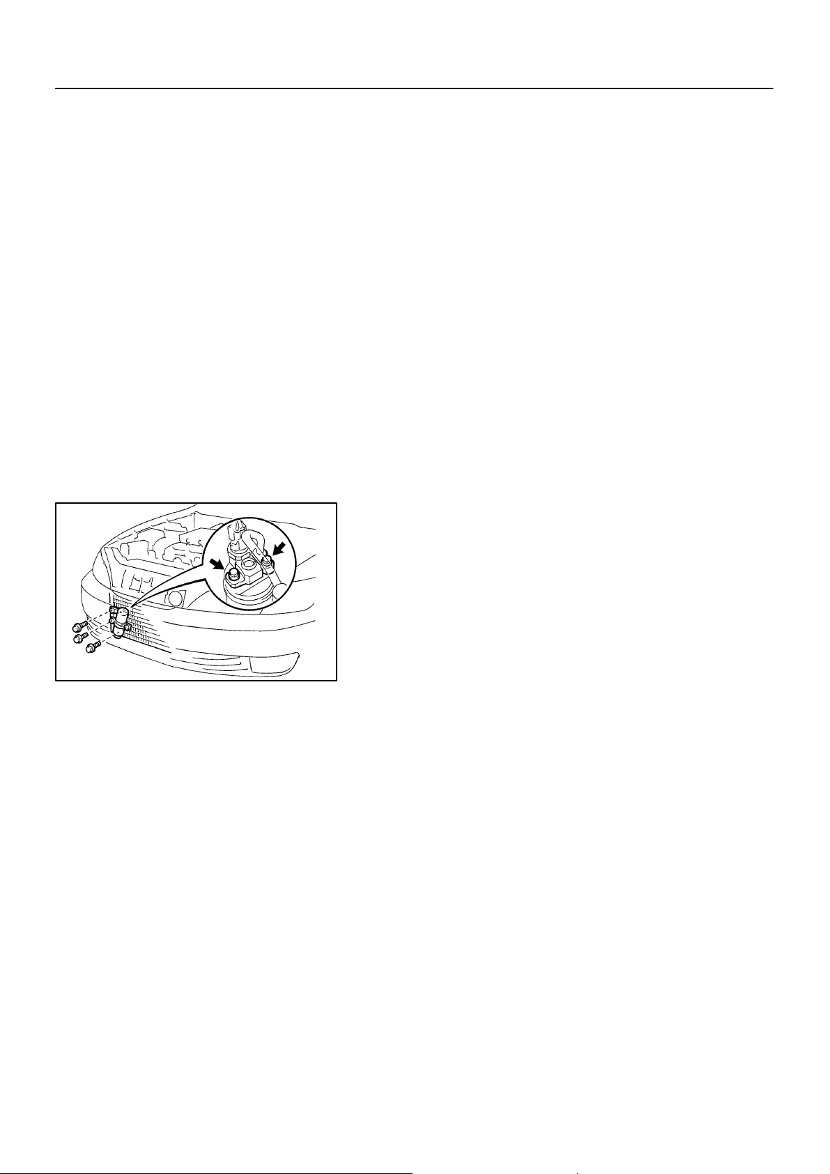
2. REMOVE RADIATOR UPPER SUPPORT SEAL
N21081
3. DISCONNECT 2 LIQUID TUBES FROM RECEIVER
Remove the 2 bolts and both tubes.
Torque: 5.4 N·m (55 kgf·cm, 48 in.·lbf)
NOTICE:
Cap the open fittings immediately to keep moisture or dirt
out of the system.
HINT:
At the time of installation, please refer to the following item.
Lubricate 2 new O–rings with compressor oil and install the
tubes.
4. REMOVE RECEIVER
(a) Remove the holder bolt and pull out receiver downward.
HINT:
At the time of installation, please refer to the following item.
If receiver is replaced, add compressor oil to receiver.
Add 20 cc (0.71 fl.oz.)
Compressor oil: ND–OIL 8 or equivalent
(b) Remove the 2 bolts and holder.
1997 LEXUS ES300 (RM511U)
1600Author: Date:
Page 44

AC–44
–AIR CONDITIONING RECEIVER
INSTALLATION
Installation is in the reverse order of removal (See page AC–43 ).
AC0A5–01
1997 LEXUS ES300 (RM511U)
1601Author: Date:
Page 45

–AIR CONDITIONING CONDENSER
CONDENSER
ON–VEHICLE INSPECTION
1. INSPECT CONDENSER FINS FOR BLOCKAGE OR DAMAGE
If the fins are clogged, wash them with water and dry with compressed air.
NOTICE:
Be careful not to damage the fins.
If the fins are bent, straighten them with a screwdriver or pliers.
2. INSPECT CONDENSER AND FITTINGS FOR LEAKAGE
Using a gas leak detector, check for leakage of refrigerant.
If there is leakage, check the tightening torque at the joints.
AC–45
AC0A8–01
1997 LEXUS ES300 (RM511U)
1602Author: Date:
Page 46
AC–46
–AIR CONDITIONING CONDENSER
AC0A9–02
REMOVAL
1. DISCHARGE REFRIGERANT FROM REFRIGERATION
SYSTEM
HINT:
At the time of installation, please refer to the following item.
Evacuate air from refrigeration system.
Charge system with refrigerant and inspect for leakage of refrigerant.
Specified amount: 800 ± 50 g (28.22 ± 1.76 oz.)
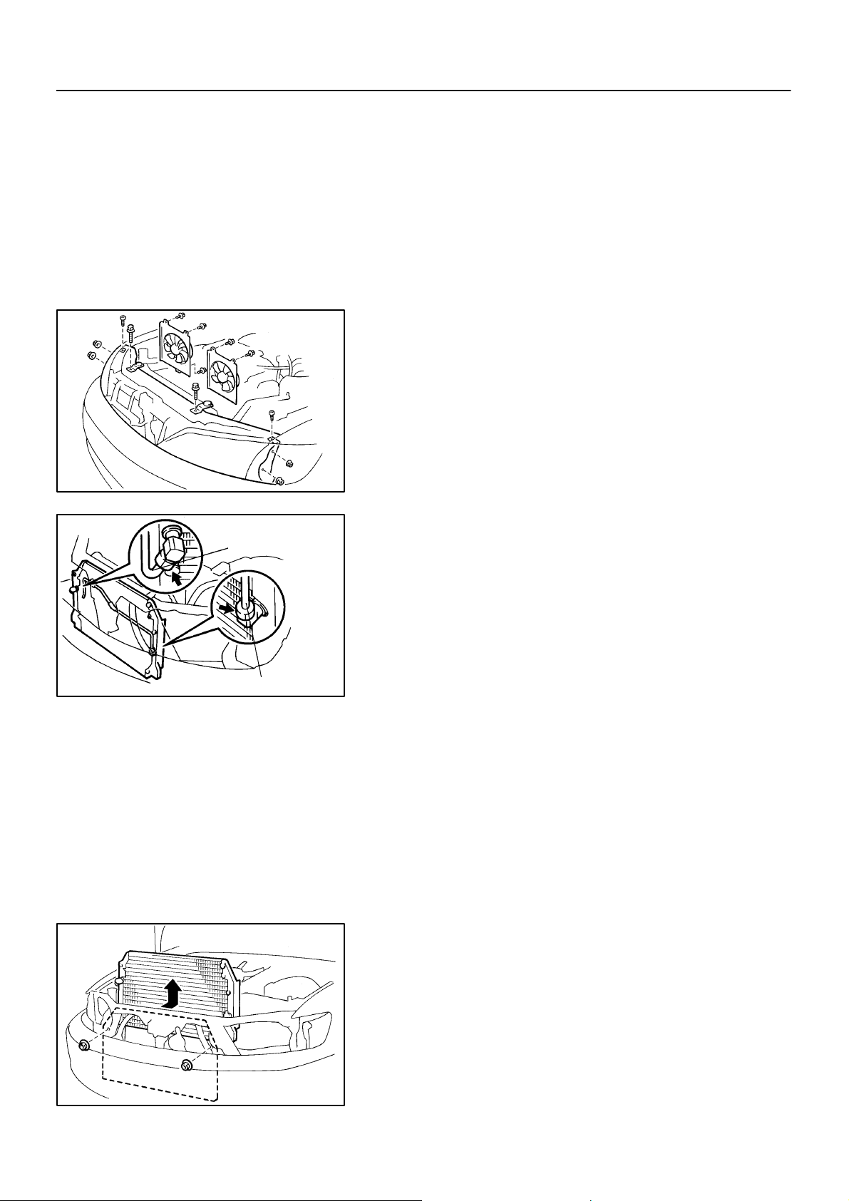
2. REMOVE THESE PARTS:
(a) Radiator upper support seal
(b) Receiver and holder
(See page AC–43)
(c) Radiator upper support
(d) Clearance lights
(e) Headlights
(f) Radiator fan and condenser fan
N21087
1997 LEXUS ES300 (RM511U)
Discharge Hose
Liquid Tube
I16648
N21085
3. DISCONNECT DISCHARGE HOSE
Loosen the nut and disconnect the discharge hose.
Torque: 22 N·m (225 kgf·cm, 16 ft·lbf)
NOTICE:
Cap the open fittings immediately to keep moisture or dirt
out of the system.
HINT:
At the time of installation, please refer to the following item
Lubricate a new O–ring with compressor oil and install the tube.
4. REMOVE LIQUID TUBE
Loosen the nut and remove the liquid tube.
Torque: 14 N·m (140 kgf·cm, 10 ft·lbf)
NOTICE:
Cap the open fittings immediately to keep moisture or dirt
out of the system.
HINT:
At the time of installation, please refer to the following item
Lubricate a new O–ring with compressor oil and install the tube.
5. REMOVE CONDENSER
(a) Remove the 2 nuts from condenser upper mountings.
(b) Push the radiator toward the engine.
(c) Push the condenser toward the radiator and pull it up-
ward.
HINT:
At the time of installation, please refer to the following item.
If condenser is replaced, add compressor oil to the compressor.
Add 40–50 cc (1.4–1.7 fl.oz.)
Compressor oil: ND–OIL 8 or equivalent
1603Author: Date:
Page 47

–AIR CONDITIONING CONDENSER
INSTALLATION
Installation is in the reverse order of removal (See page AC–46 ).
AC–47
AC0AA–01
1997 LEXUS ES300 (RM511U)
1604Author: Date:
Page 48
AC–48
–AIR CONDITIONING EVAPORATOR
N21063
EVAPORATOR
AC0AB–02
REMOVAL
1. DISCHARGE REFRIGERANT FROM REFRIGERATION
SYSTEM
HINT:
At the time of installation, please refer to the following item.
Evacuate air from refrigeration system.
Charge system with refrigerant and inspect for leakage of refrigerant.
Specified amount: 800 ± 50 g (28.22 ± 1.76 oz.)
2. REMOVE BLOWER UNIT
(See page AC–29)
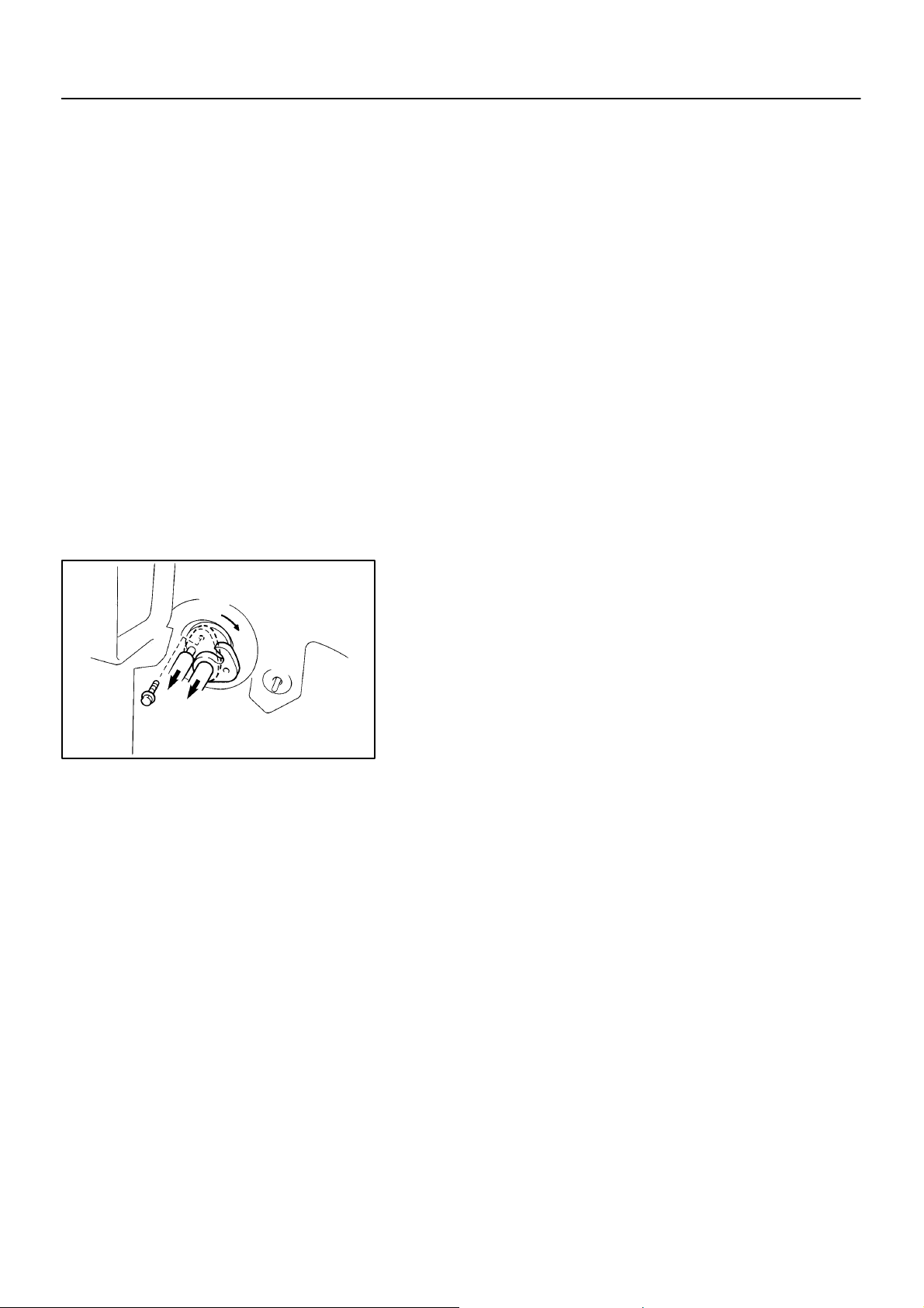
3. DISCONNECT LIQUID AND SUCTION TUBE
Remove the bolt and slide the plate, then disconnect both
tubes.
Torque: 10 N·m (100 kgf·cm, 7 ft·lbf)
NOTICE:
Cap the open fittings immediately to keep moisture or dirt
out of the system.
HINT:
At the time of installation, please refer to the following item.
Lubricate 2 new O–rings with compressor oil and install the
tubes.
1997 LEXUS ES300 (RM511U)
1605Author: Date:
Page 49
N21091
AC–49
–AIR CONDITIONING EVAPORATOR
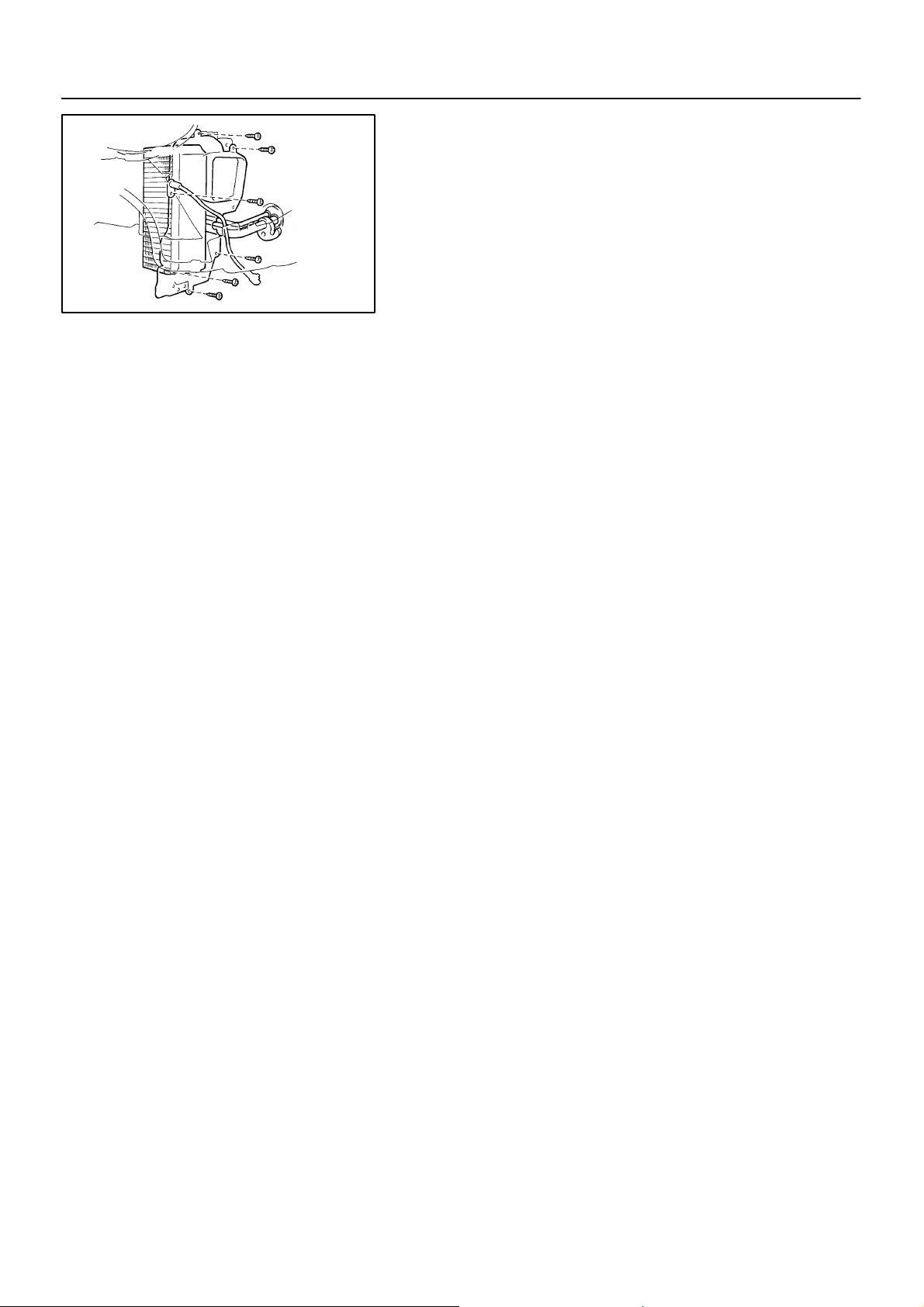
4. REMOVE EVAPORATOR
(a) Disconnect the connector.
(b) Remove the screw and pull out the evaporator temp. sen-
sor.
(c) Remove the 5 screws and evaporator cover.
HINT:
At the time of installation, please refer to the following item.
Do not reuse the evaporator cover.
(d) Pull out the evaporator.
HINT:
At the time of installation, please refer to the following item.
If evaporator is replaced, add compressor oil to evaporator.
Add 40 cc (1.4 fl.oz.)
Compressor oil: ND–OIL 8 or equivalent
1997 LEXUS ES300 (RM511U)
1606Author: Date:
Page 50

–AIR CONDITIONING EVAPORATOR
INSTALLATION
Installation is in the reverse order of removal (See page AC–48 ).
AC–51
AC0AD–01
1997 LEXUS ES300 (RM511U)
1608Author: Date:
Page 51
AC–52
–AIR CONDITIONING HEATER RADIATOR
N21092
N21061
HEATER RADIATOR
AC0AE–01
REMOVAL
1. DRAIN ENGINE COOLANT FROM RADIATOR
HINT:
It is not necessary to drain out all coolant.
2. REMOVE THESE PARTS:
(a) No.1 lower panel
(b) Lower panel LH
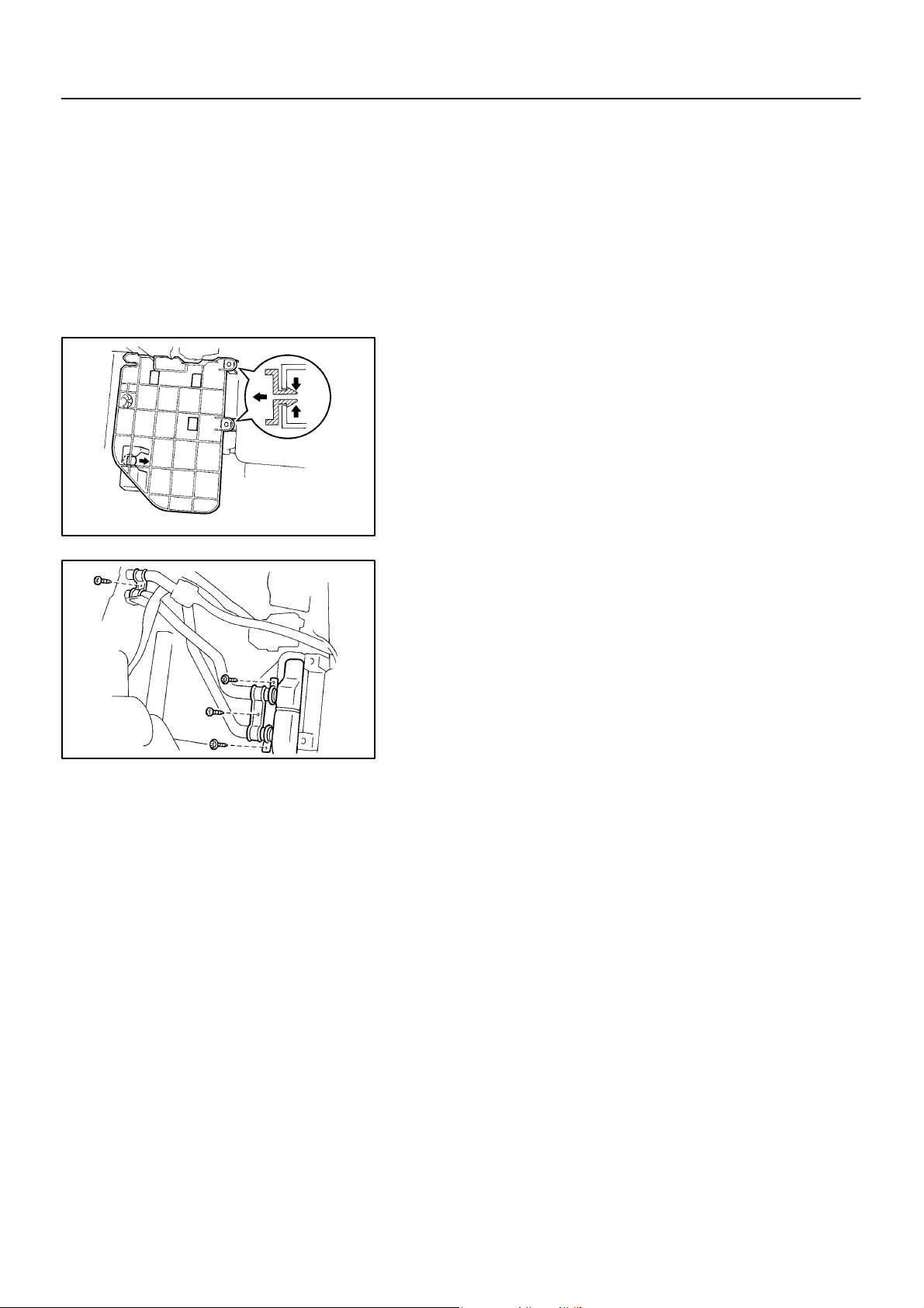
3. REMOVE HEATER RADIATOR
(a) Release the 3 claws and remove the heater protector.
(b) Remove 2 screws and 2 clamps.
(c) Remove the 2 screws and 2 clips, then disconnect the
heater radiator pipes from heater radiator.
(d) Remove 2 O–rings from heater radiator pipes.
HINT:
At the time of installation, please refer to the following item.
Do not reuse 2 O–rings.
(e) Pull out the heater radiator.
1997 LEXUS ES300 (RM511U)
1609Author: Date:
Page 52

–AIR CONDITIONING HEATER RADIATOR
INSPECTION
INSPECT FINS FOR BLOCKAGE
If the fins are clogged, clean them with compressed air.
AC–53
AC0AF–01
1997 LEXUS ES300 (RM511U)
1610Author: Date:
Page 53

AC–54
–AIR CONDITIONING HEATER RADIATOR
INSTALLATION
Installation is in the reverse order of removal (See page AC–52 ).
AC0AG–01
1997 LEXUS ES300 (RM511U)
1611Author: Date:
Page 54

–AIR CONDITIONING EXPANSION VALVE
EXPANSION VALVE
ON–VEHICLE INSPECTION
1. CHECK QUANTITY OF GAS IN REFRIGERATION CYCLE
2. SET ON MANIFOLD GAUGE SET
(See page AC–17)
3. RUN ENGINE
Run the engine at 1,500 rpm for at least 5 minutes.
2
Then check that the high pressure reading is 1.37 – 1.57 MPa (14 – 16 kgf/cm
4. CHECK EXPANSION VALVE
If the expansion valve is faulty, the low pressure reading will drop to 0 kPa (0 kgf/cm
HINT:
2
When the low pressure drops to 0 kPa (0 kgf/cm
, 0 pis), check the receiver’s IN and OUT sides for no tem-
perature difference.
, 199 –228 psi).
2
, 0 psi).
AC–55
AC0AH–01
1997 LEXUS ES300 (RM511U)
1612Author: Date:
Page 55
AC–56
N21066
–AIR CONDITIONING EXPANSION VALVE
AC0AI–02
REMOVAL
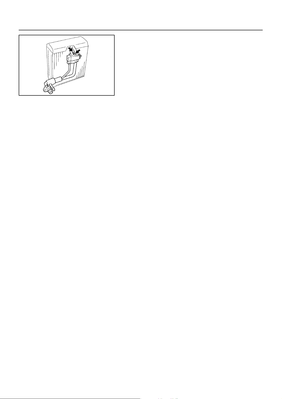
1. REMOVE EVAPORATOR
(See page AC–48)
2. REMOVE EXPANSION VALVE
Using a hexagon wrench, remove the 2 bolts and separate the
expansion valve, evaporator and tube.
Torque: 5.4 N·m (55 kgf·cm, 48 in.·lbf)
HINT:
At the time of installation, please refer to the following item.
Lubricate 4 new O–rings with compressor oil and install the tube
and valve.
1997 LEXUS ES300 (RM511U)
1613Author: Date:
Page 56

–AIR CONDITIONING EXPANSION VALVE
INSTALLATION
Installation is in the reverse order of removal (See page AC–56 ).
AC–57
AC0AJ–01
1997 LEXUS ES300 (RM511U)
1614Author: Date:
Page 57

AC–58
–AIR CONDITIONING WATER VALVE
WATER VALVE
ON–VEHICLE INSPECTION
1. WARM UP ENGINE
2. DISCONNECT WATER VALVE CONTROL CABLE
3. INSPECT WATER VALVE OPERATION
(a) Check that warm air blown out when the water valve lever is moved to ”WARM” position.
(b) Check that cool air blown out when the water valve is moved to the ”COOL” position.
If operation is not as specified, replace the water valve.
4. CONNECT WATER VALVE CONTROL CABLE
HINT:
After connection, adjust the control cable.
AC0AK–01
1997 LEXUS ES300 (RM511U)
1615Author: Date:
Page 58
AC–59
–AIR CONDITIONING WATER VALVE
AC0AL–02
REMOVAL
1. DRAIN ENGINE COOLANT FROM RADIATOR
HINT:
It is not necessary to drain out all the coolant.
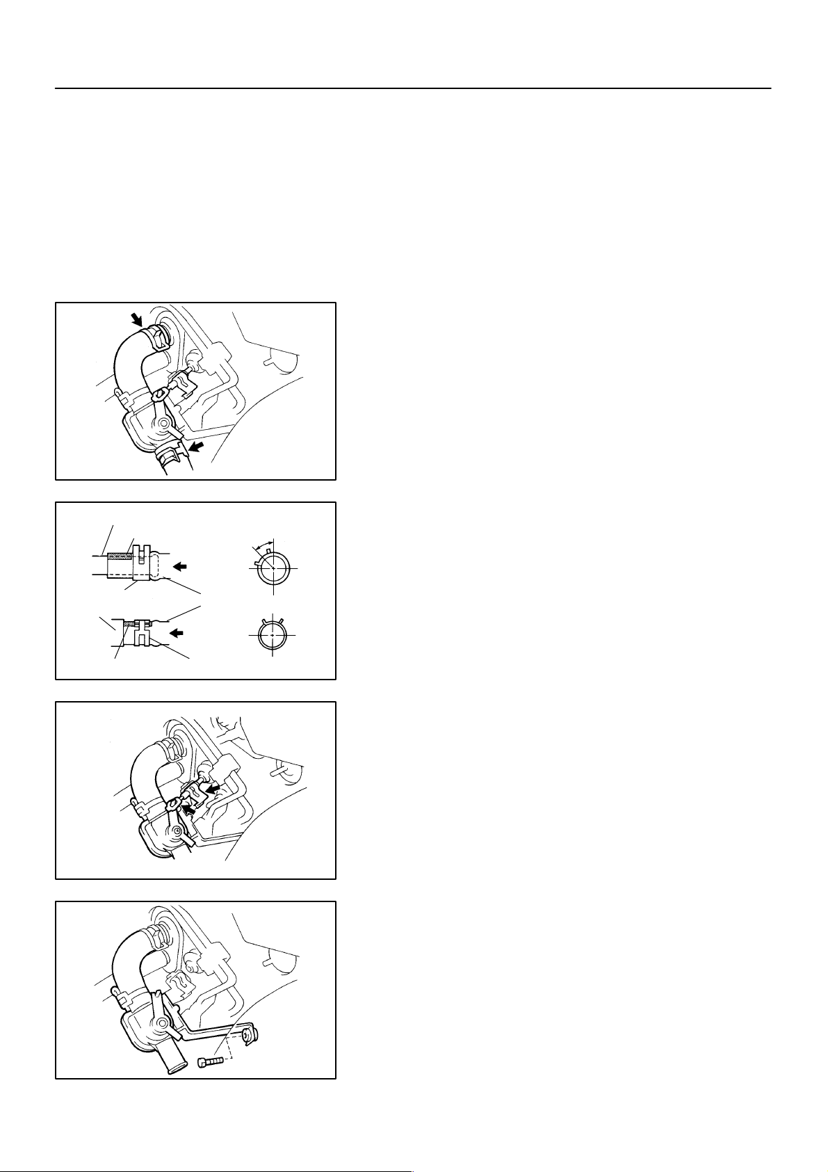
2. DISCONNECT WATER HOSES FROM WATER VALVE
AND HEATER RADIATOR PIPE
(a) Using pliers, grip the claws of the hose clip and slide the
hose clip along the hose.
(b) Disconnect the water hose.
Heater Radiator Pipe
Marking
Hose Clip
Water Valve
Marking
Water Hose
Hose Clip
45 ± 10°
RH
Fr.
Upper
Lower
N21070
LH
Rr.
N21068
N21071
HINT:
At the time of installation, please refer to the following items.
Push the water hose onto the heater radiator pipe as far
as the pipe grommet.
Install the hose clip in a position, as shown in the illustra-
tion.
3. DISCONNECT WATER VALVE CONTROL CABLE
FROM WATER VALVE
HINT:
At the time of installation, please refer to the following item.
For installing the control cable, refer to ”INSTALLATION”.
1997 LEXUS ES300 (RM511U)
4. REMOVE WATER VALVE
Remove the bolt and water valve.
N21072
1616Author: Date:
Page 59
AC–60
To COOL
Clamp
N01181
–AIR CONDITIONING WATER VALVE
AC0AM–02
INSTALLATION
Installation is in the reverse order of removal (See page
AC–59).
HINT:
After installation, adjust water valve control cable.
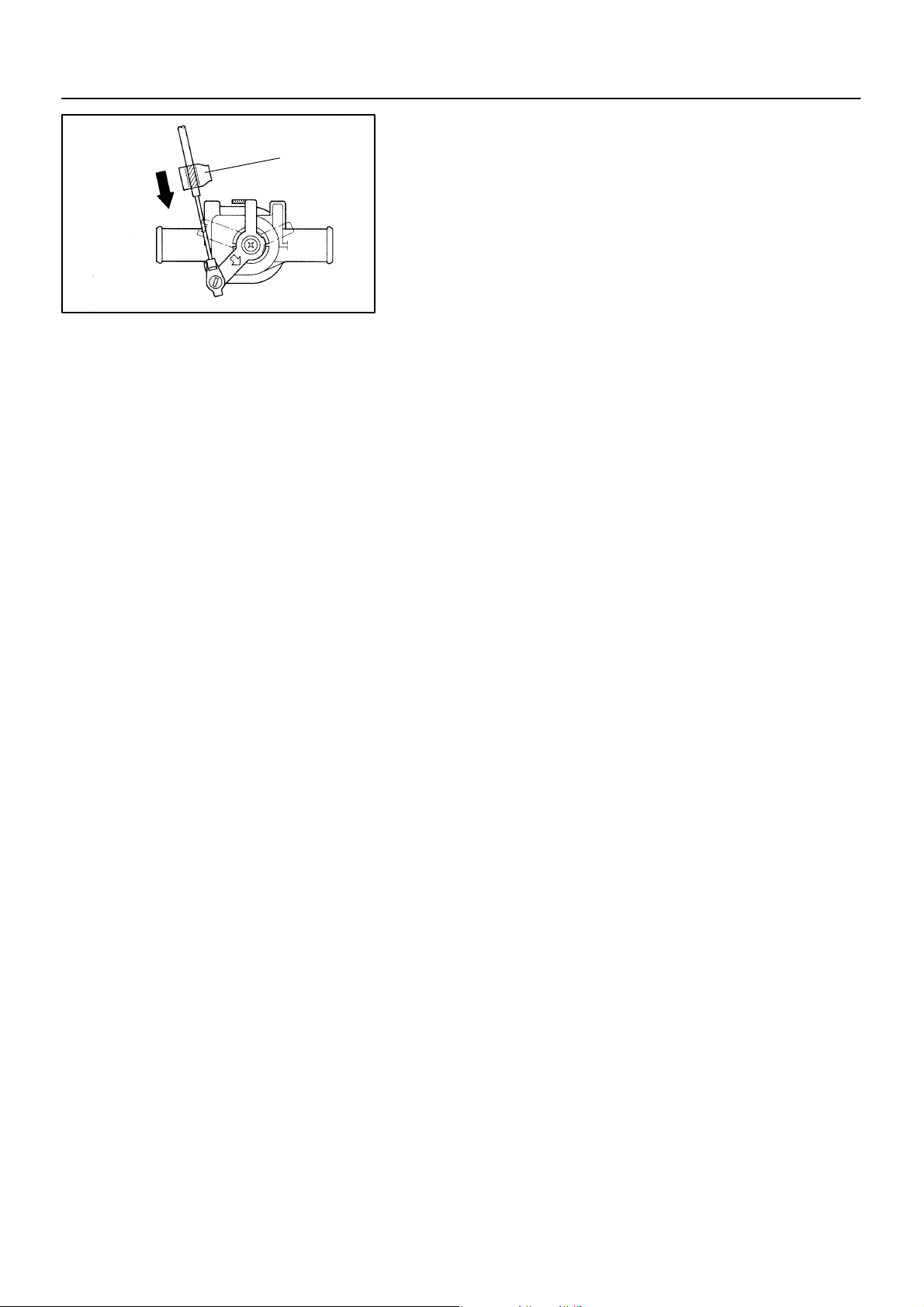
ADJUST WATER VALVE CONTROL CABLE
(a) Turn ignition switch to ON.
(b) Set temperature control switch at ”COOL”.
(c) Set the water valve control lever on the ”COOL” position
and install the control cable and lock the clamp.
HINT:
Lock the clamp while lightly pushing the outer cable in the direction shown by arrow.
1997 LEXUS ES300 (RM511U)
1617Author: Date:
Page 60
–AIR CONDITIONING BLOWER MOTOR
AC–61
N21089
BLOWER MOTOR
AC0AN–02
REMOVAL
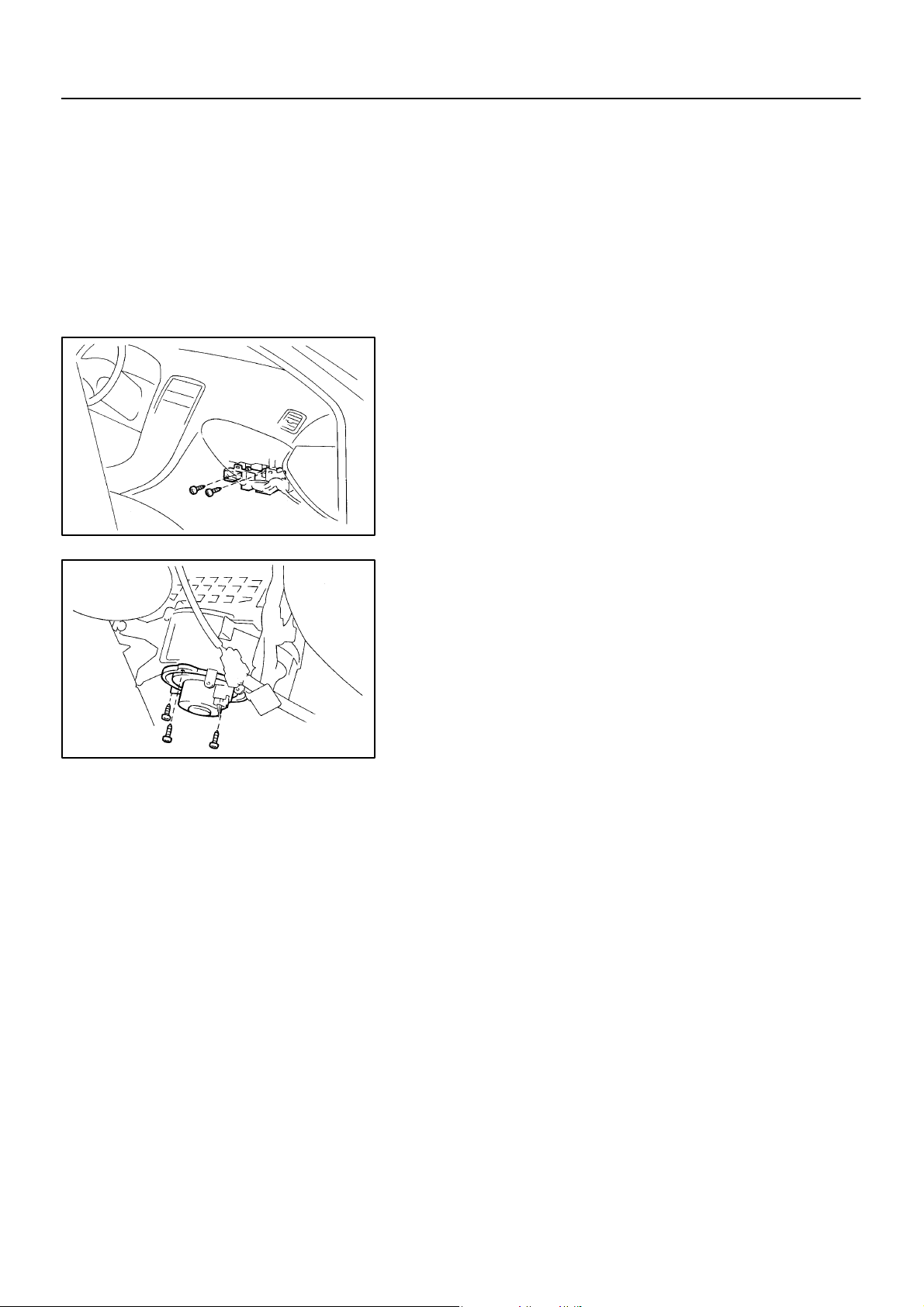
1. REMOVE THESE PARTS:
(a) Cowl side trim RH
(b) Front door scuff plate RH
(c) No. 2 instrument panel under cover
2. REMOVE 2 CONNECTOR BRACKET SET SCREWS
3. REMOVE BLOWER MOTOR
(a) Disconnect the connector.
(b) Remove the 3 screws and blower motor.
N21064
1997 LEXUS ES300 (RM511U)
1618Author: Date:
Page 61

AC–62
INSPECTION
INSPECT BLOWER MOTOR CIRCUIT
(See page DI–583)
–AIR CONDITIONING BLOWER MOTOR
AC0AO–02
1997 LEXUS ES300 (RM511U)
1619Author: Date:
Page 62

–AIR CONDITIONING BLOWER MOTOR
INSTALLATION
Installation is in the reverse order of removal (See page AC–61 ).
AC–63
AC0AP–01
1997 LEXUS ES300 (RM511U)
1620Author: Date:
Page 63
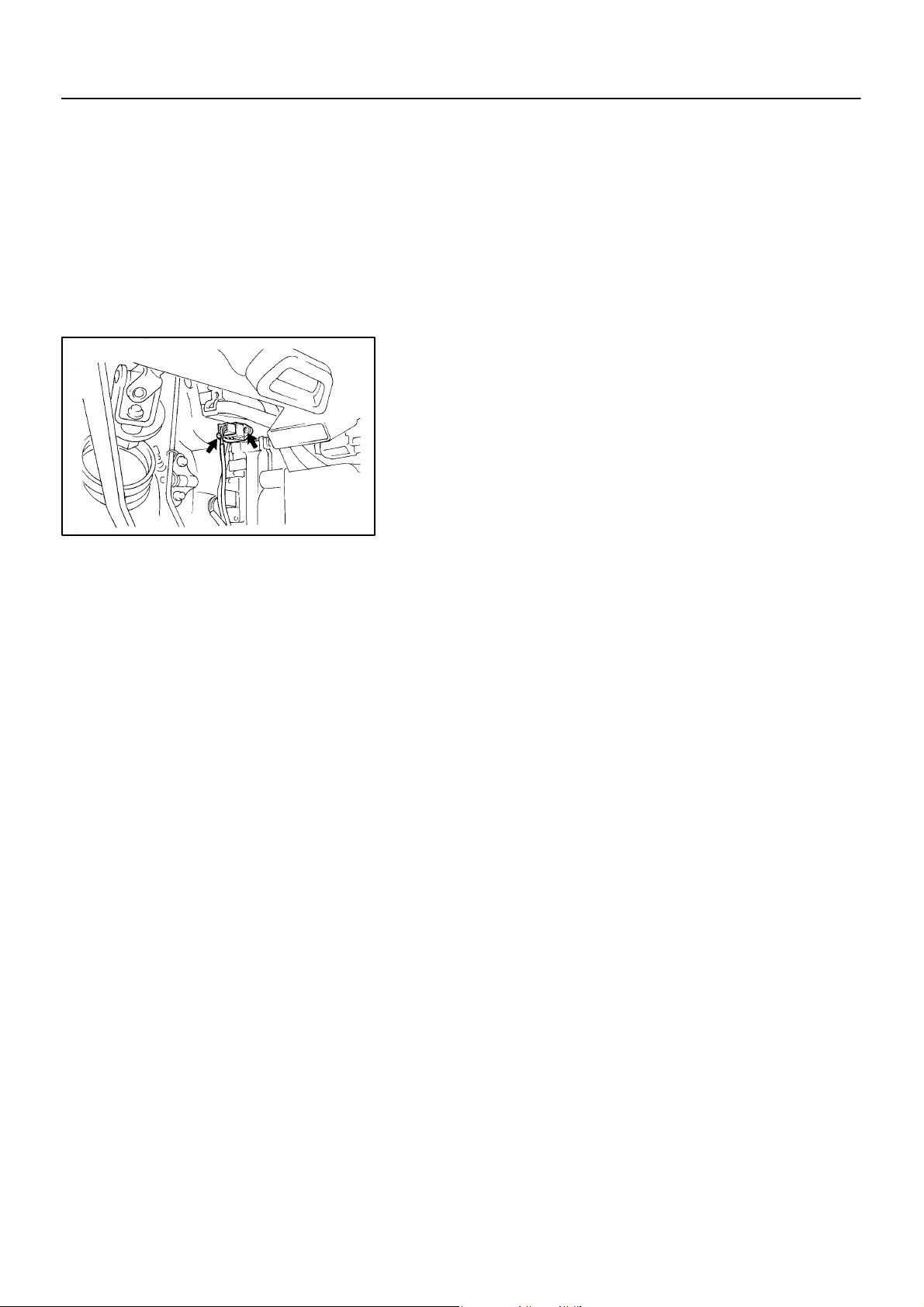
AC–64
–AIR CONDITIONING BLOWER RESISTOR
N12077
BLOWER RESISTOR
REMOVAL
1. REMOVE THESE PARTS:
(a) No. 1 instrument lower panel
(b) Instrument lower panel LH
2. REMOVE BLOWER RESISTOR
(a) Disconnect the connector.
(b) Remove the 2 screws and blower resistor.
AC0AQ–02
1997 LEXUS ES300 (RM511U)
1621Author: Date:
Page 64

AC–65
–AIR CONDITIONING BLOWER RESISTOR
AC2SZ–01
INSPECTION
INSPECT BLOWER RESISTOR RESISTANCE
Measure resistance between terminals.
Standard resistance:
12
Z14433
1.8 – 2.2 Ω
If resistance is not as specified, replace the blower resistor.
1997 LEXUS ES300 (RM511U)
1622Author: Date:
Page 65

AC–66
–AIR CONDITIONING BLOWER RESISTOR
INSTALLATION
Installation is in the reverse order of removal (See page AC–64 ).
AC0AS–01
1997 LEXUS ES300 (RM511U)
1623Author: Date:
Page 66
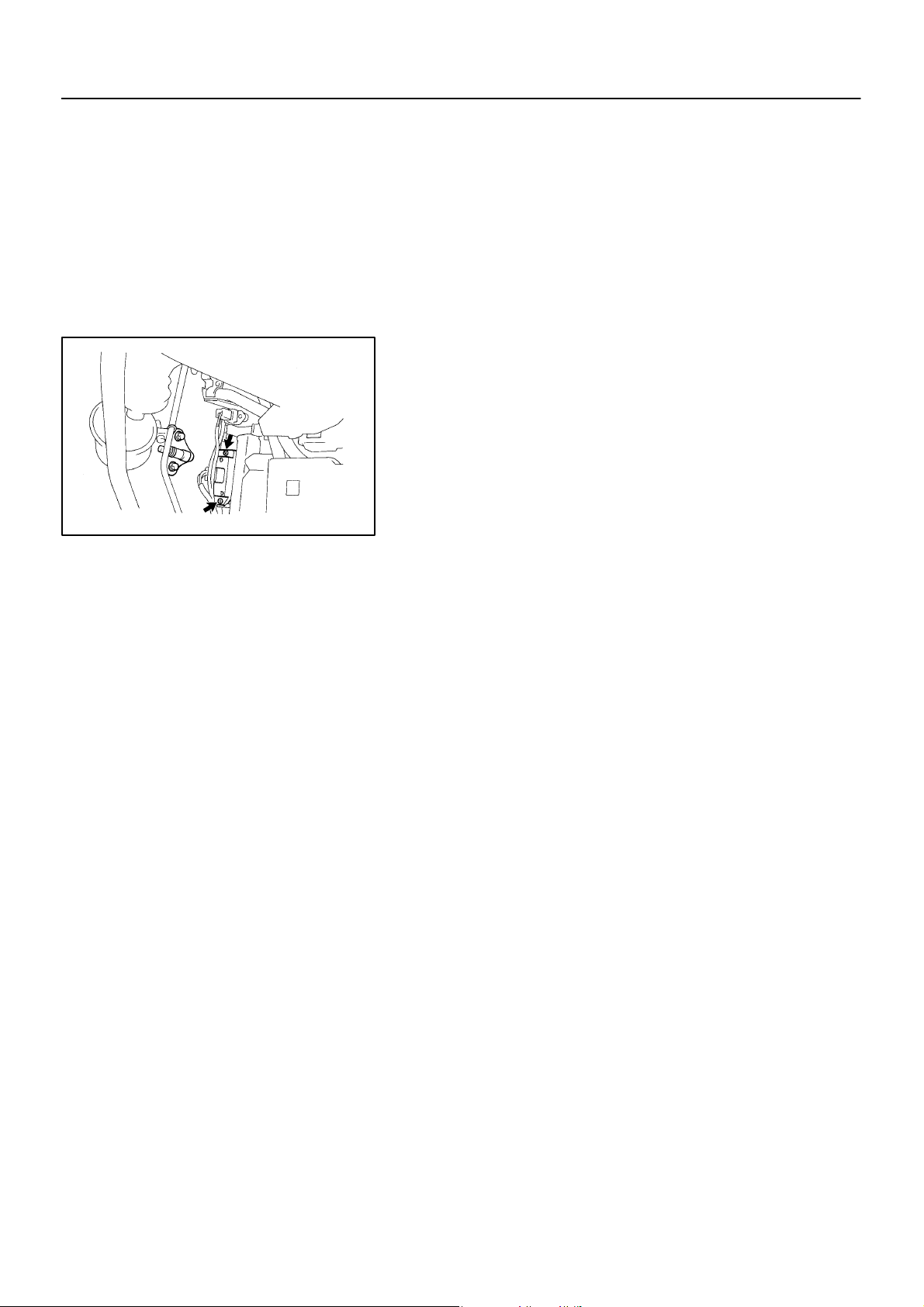
–AIR CONDITIONING BLOWER MOTOR LINEAR CONTROLLER
BLOWER MOTOR LINEAR
AC–67
N12820
CONTROLLER
AC0AT–02
REMOVAL
1. REMOVE THESE PARTS:
(a) No. 1 instrument lower panel
(b) Instrument lower panel LH
2. REMOVE BLOWER MOTOR LINEAR CONTROLLER
(a) Disconnect the connector.
(b) Remove the 2 screws and controller.
1997 LEXUS ES300 (RM511U)
1624Author: Date:
Page 67

AC–68
–AIR CONDITIONING BLOWER MOTOR LINEAR CONTROLLER
INSPECTION
INSPECT BLOWER MOTOR LINEAR CONTROLLER CIRCUIT
(See page DI–583)
AC0AU–02
1997 LEXUS ES300 (RM511U)
1625Author: Date:
Page 68

–AIR CONDITIONING BLOWER MOTOR LINEAR CONTROLLER
INSTALLATION
Installation is in the reverse order of removal (See page AC–67 ).
AC–69
AC0AV–01
1997 LEXUS ES300 (RM511U)
1626Author: Date:
Page 69
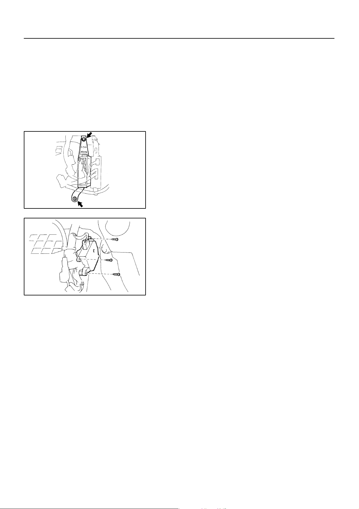
AC–70
–AIR CONDITIONING AIR INLET SERVOMOTOR
N21073
AIR INLET SERVOMOTOR
REMOVAL
1. REMOVE THESE PARTS:
(a) Cowl side trim RH
(b) Front door scuff plate RH
(c) No. 2 instrument panel under cover
(d) Glove compartment
2. REMOVE ECM
(a) Disconnect the connectors.
(b) Remove the 2 nuts and ECM.
3. REMOVE AIR INLET SERVOMOTOR
(a) Disconnect the connector.
(b) Remove the 3 screws and servomotor.
AC0AW–02
N21074
1997 LEXUS ES300 (RM511U)
1627Author: Date:
Page 70

–AIR CONDITIONING AIR INLET SERVOMOTOR
INSPECTION
1. INSPECT AIR INLET SERVOMOTOR CIRCUIT
(See page DI–566)
2. INSPECT AIR INLET DAMPER POSITION SENSOR CIRCUIT
(See page DI–560)
AC–71
AC0AX–01
1997 LEXUS ES300 (RM511U)
1628Author: Date:
Page 71

AC–72
–AIR CONDITIONING AIR INLET SERVOMOTOR
INSTALLATION
Installation is in the reverse order of removal (See page AC–70 ).
AC0AY–01
1997 LEXUS ES300 (RM511U)
1629Author: Date:
Page 72
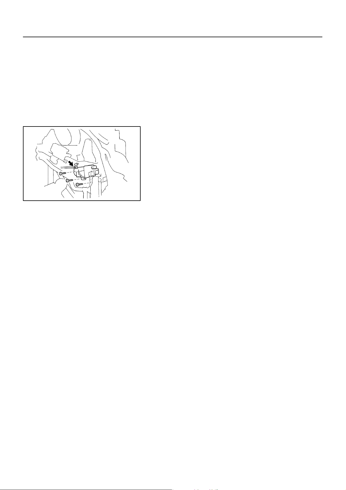
–AIR CONDITIONING AIR MIX SERVOMOTOR
AC–73
N21060
AIR MIX SERVOMOTOR
AC0AZ–02
REMOVAL
1. REMOVE THESE PARTS:
(a) No. 1 instrument lower panel
(b) Instrument lower panel LH
2. REMOVE AIR MIX SERVOMOTOR
(a) Disconnect the connector.
(b) Remove the 3 screws and servomotor, then disconnect
the control cable.
1997 LEXUS ES300 (RM511U)
1630Author: Date:
Page 73

AC–74
–AIR CONDITIONING AIR MIX SERVOMOTOR
INSPECTION
1. INSPECT AIR MIX SERVOMOTOR CIRCUIT
(See page DI–563)
2. INSPECT AIR MIX DAMPER POSITION SENSOR CIRCUIT
(See page DI–557)
AC0B0–01
1997 LEXUS ES300 (RM511U)
1631Author: Date:
Page 74

–AIR CONDITIONING AIR MIX SERVOMOTOR
INSTALLATION
Installation is in the reverse order of removal (See page AC–73 ).
AC–75
AC0B1–01
1997 LEXUS ES300 (RM511U)
1632Author: Date:
Page 75
AC–76
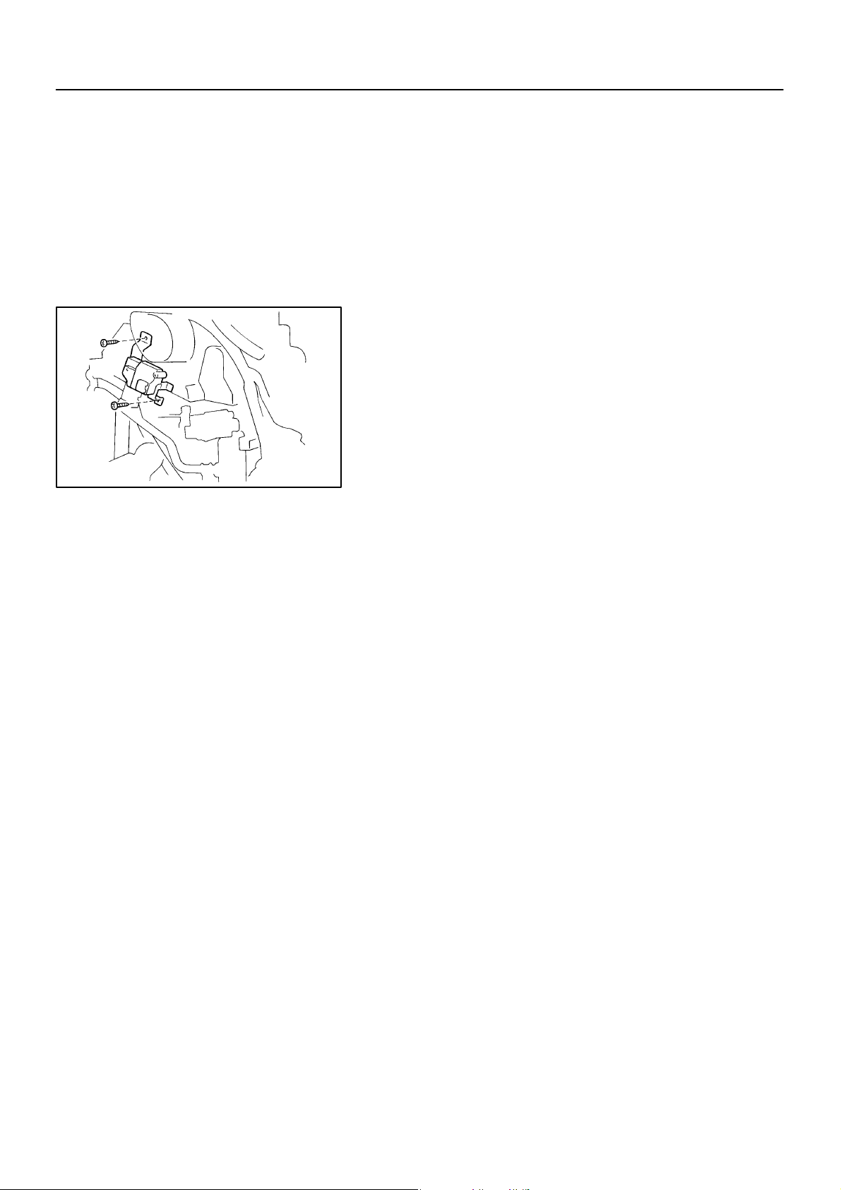
–AIR CONDITIONING AIR OUTLET SERVOMOTOR
N21059
AIR OUTLET SERVOMOTOR
REMOVAL
1. REMOVE THESE PARTS:
(a) No. 1 instrument lower panel
(b) Instrument lower panel LH
2. REMOVE AIR OUTLET SERVOMOTOR
(a) Disconnect the connector.
(b) Remove the 2 screws and servomotor.
AC0B2–02
1997 LEXUS ES300 (RM511U)
1633Author: Date:
Page 76

INSPECTION
INSPECT AIR OUTLET SERVOMOTOR CIRCUIT
(See page DI–574)
AC–77
–AIR CONDITIONING AIR OUTLET SERVOMOTOR
AC0B3–02
1997 LEXUS ES300 (RM511U)
1634Author: Date:
Page 77

AC–78
–AIR CONDITIONING AIR OUTLET SERVOMOTOR
INSTALLATION
Installation is in the reverse order of removal (See page AC–76 ).
AC0B4–01
1997 LEXUS ES300 (RM511U)
1635Author: Date:
Page 78
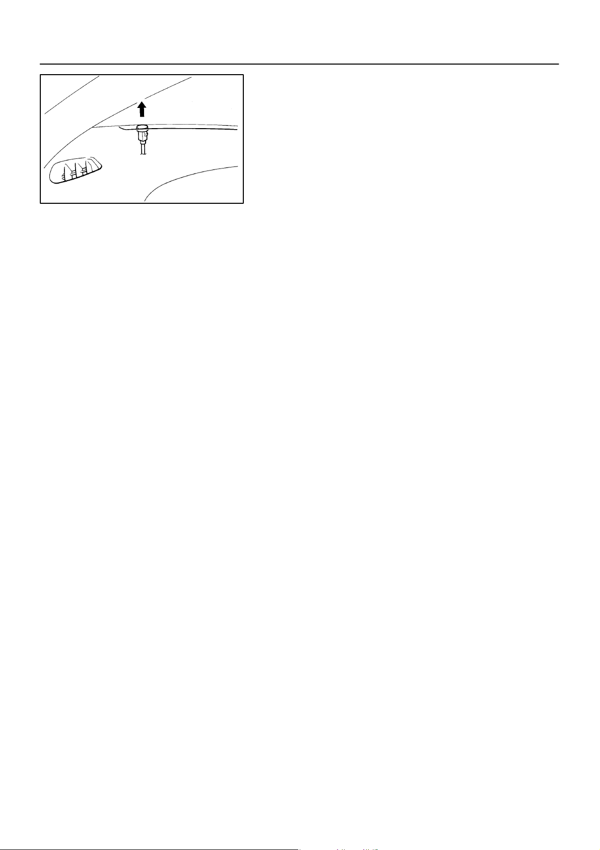
–AIR CONDITIONING SOLAR SENSOR
AC–79
N21083
SOLAR SENSOR
AC0B5–01
REMOVAL
REMOVE SOLAR SENSOR
Using a screwdriver, pull out the sensor, then disconnect the
connector.
HINT:
Tape the screwdriver tip before use.
1997 LEXUS ES300 (RM511U)
1636Author: Date:
Page 79

AC–80
INSPECTION
INSPECT SOLAR SENSOR CIRCUIT
(See page DI–549)
–AIR CONDITIONING SOLAR SENSOR
AC0B6–01
1997 LEXUS ES300 (RM511U)
1637Author: Date:
Page 80

–AIR CONDITIONING SOLAR SENSOR
INSTALLATION
Installation is in the reverse order of removal (See page AC–79 ).
AC–81
AC0B7–01
1997 LEXUS ES300 (RM511U)
1638Author: Date:
Page 81
AC–82
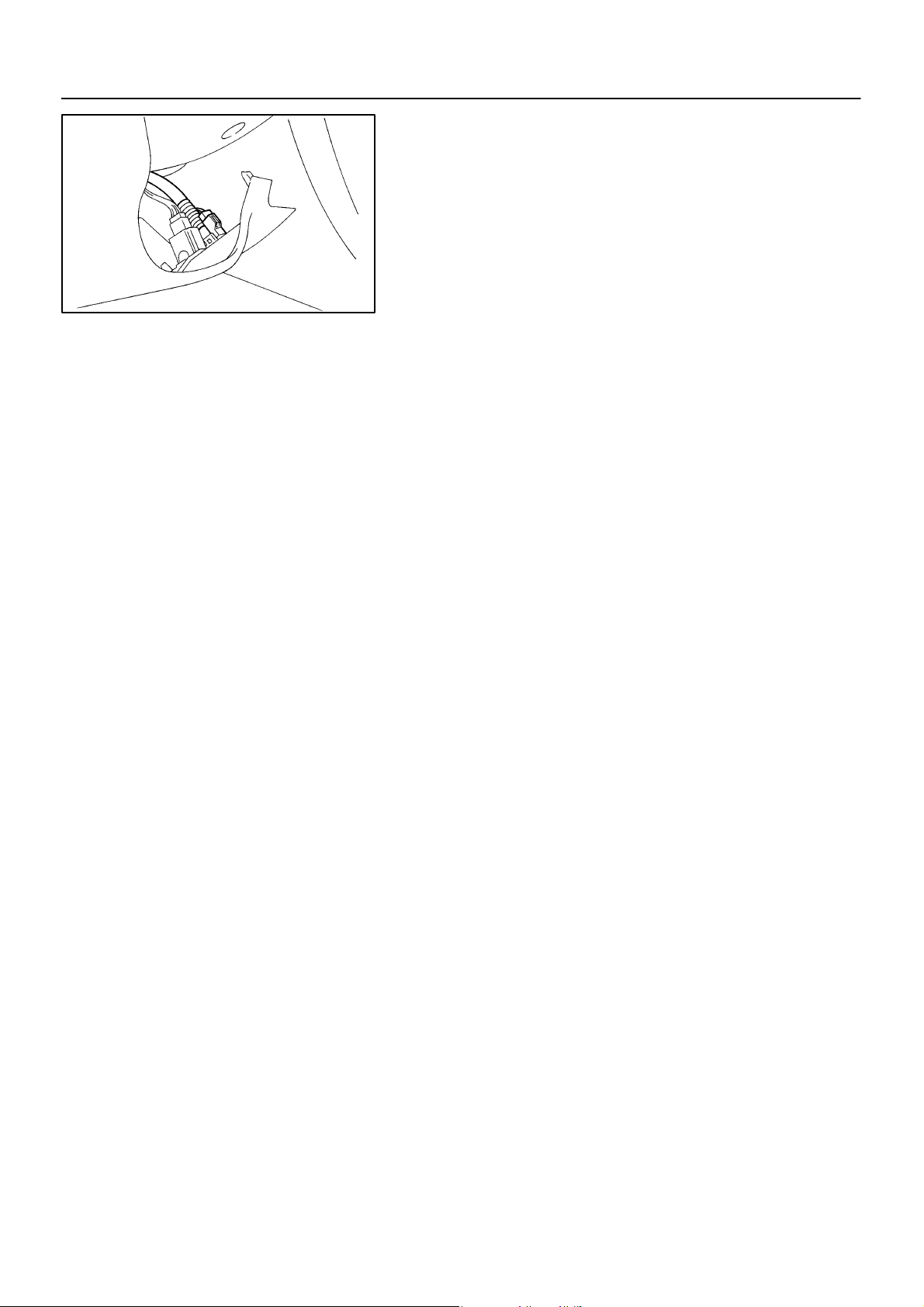
–AIR CONDITIONING ROOM TEMPERATURE SENSOR
N21090
ROOM TEMPERATURE SENSOR
AC0B8–02
REMOVAL
REMOVE ROOM TEMP. SENSOR
(a) Remove the No. 1 instrument lower panel set screws.
(b) Disconnect the aspirator hose.
(c) Disconnect the connector.
(d) Release the 2 claws and pull out the sensor from No. 1
instrument lower panel.
1997 LEXUS ES300 (RM511U)
1639Author: Date:
Page 82

INSPECTION
INSPECT ROOM TEMP. SENSOR CIRCUIT
(See page DI–537)
AC–83
–AIR CONDITIONING ROOM TEMPERATURE SENSOR
AC0B9–01
1997 LEXUS ES300 (RM511U)
1640Author: Date:
Page 83

AC–84
–AIR CONDITIONING ROOM TEMPERATURE SENSOR
INSTALLATION
Installation is in the reverse order of removal (See page AC–82 ).
AC0BA–01
1997 LEXUS ES300 (RM511U)
1641Author: Date:
Page 84
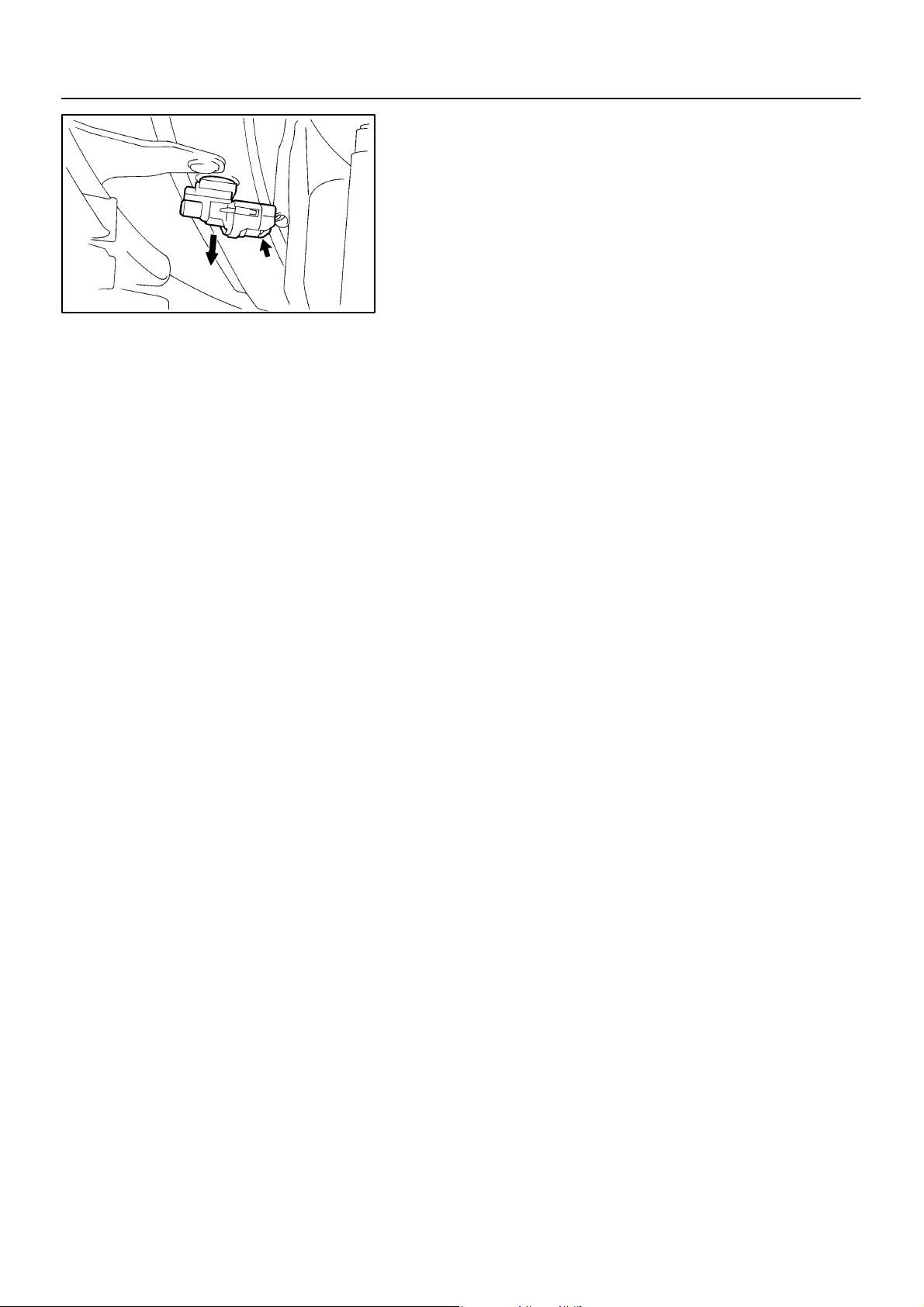
–AIR CONDITIONING AMBIENT TEMPERATURE SENSOR
AMBIENT TEMPERATURE
AC–85
N21077
SENSOR
REMOVAL
REMOVE AMBIENT TEMPERATURE SENSOR
(a) Disconnect the connector.
(b) Pull out the sensor from bumper reinforcement.
AC0BE–01
1997 LEXUS ES300 (RM511U)
1642Author: Date:
Page 85

AC–86
–AIR CONDITIONING AMBIENT TEMPERATURE SENSOR
INSPECTION
INSPECT AMBIENT TEMPERATURE SENSOR CIRCUIT
(See page DI–540)
AC0BF–01
1997 LEXUS ES300 (RM511U)
1643Author: Date:
Page 86

–AIR CONDITIONING AMBIENT TEMPERATURE SENSOR
INSTALLATION
Installation is in the reverse order of removal (See page AC–85 ).
AC–87
AC0BG–01
1997 LEXUS ES300 (RM511U)
1644Author: Date:
Page 87
AC–88
–AIR CONDITIONING EVAPORATOR TEMPERATURE SENSOR
EVAPORATOR TEMPERATURE
SENSOR
REMOVAL
1. REMOVE THESE PARTS:
(a) Cowl side trim RH
(b) Front door scuff plate RH
(c) No. 2 instrument panel under cover
(d) Glove compartment
(e) w/ CD Changer:
Finish upper panel
(f) w/ CD Changer:
CD changer assembly
(g) Audio amplifier
(h) ECM
(i) Blower unit (See page AC–29 )
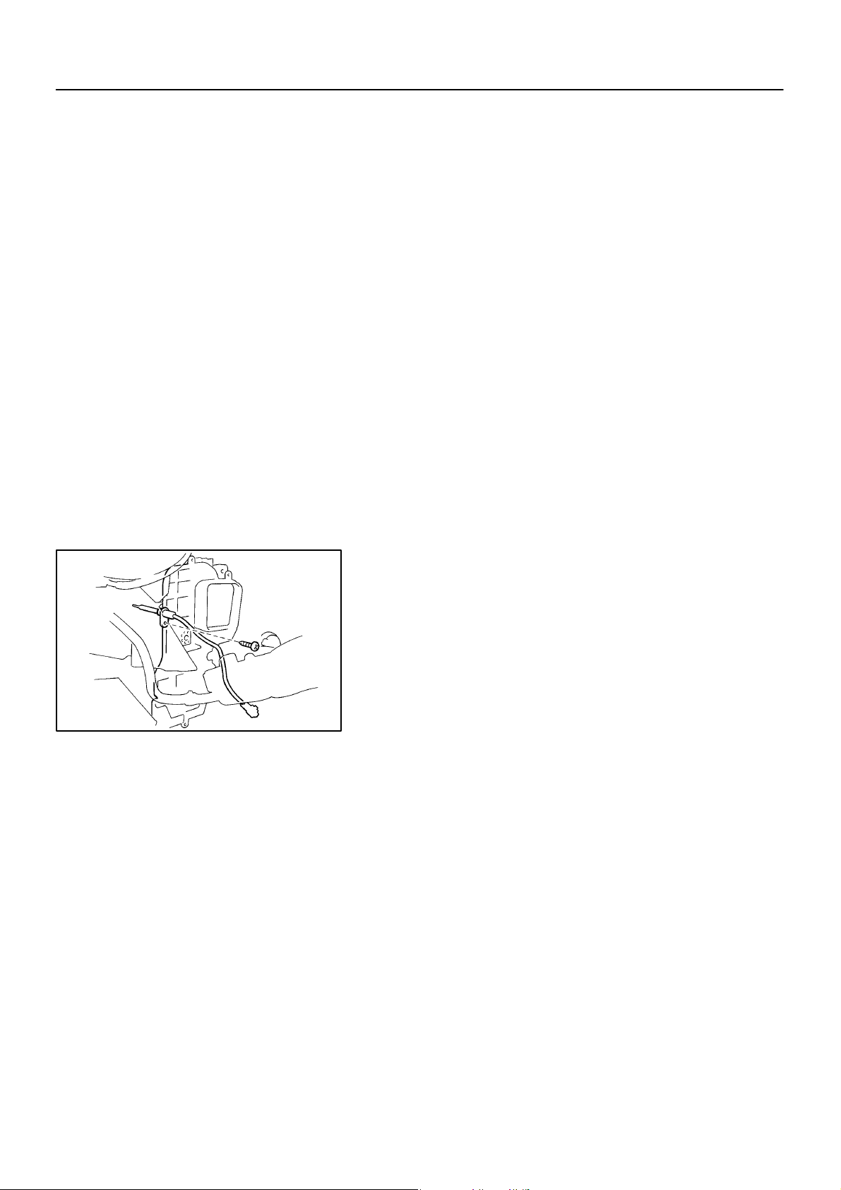
2. REMOVE EVAPORATOR TEMP. SENSOR
(a) Disconnect the connector.
(b) Remove the screw and pull out the sensor.
AC0BB–02
1997 LEXUS ES300 (RM511U)
N21062
1645Author: Date:
Page 88

INSPECTION
INSPECT EVAPORATOR TEMP. SENSOR CIRCUIT
(See page DI–543)
AC–89
–AIR CONDITIONING EVAPORATOR TEMPERATURE SENSOR
AC0BC–01
1997 LEXUS ES300 (RM511U)
1646Author: Date:
Page 89

AC–90
–AIR CONDITIONING EVAPORATOR TEMPERATURE SENSOR
INSTALLATION
Installation is in the reverse order of removal (See page AC–88 ).
AC0BD–01
1997 LEXUS ES300 (RM511U)
1647Author: Date:
Page 90
–AIR CONDITIONING PRESSURE SWITCH
AC–91
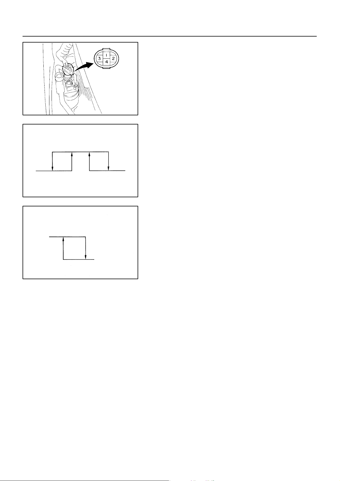
Magnetic Clutch Control
Low Pressure Side
196 kpa
(2.0 kgf·cm2, 28 psi)
OFF (No Continuity)
Cooling Fan Control
ON
(Continuity)
1,226 kpa
(12.5 kgf·cm2, 178 psi)
N20291
High Pressure Side
ON (Continuity)
3,140 kpa
(32.0 kgf·cm2, 455 psi)
OFF (No Continuity)
Z13470
1,520 kpa
(15.5 kgf·cm2, 220 psi)
OFF
(No Continuity)
Z13471
PRESSURE SWITCH
AC0BH–01
ON–VEHICLE INSPECTION
1. SET ON MANIFOLD GAUGE SET
(See page AC–17)
2. DISCONNECT CONNECTOR FROM PRESSURE
SWITCH
3. RUN ENGINE AT APPROX. 1,500 RPM
4. Magnetic Clutch Control:
INSPECT PRESSURE SWITCH OPERATION
(a) Connect the positive (+) lead from the ohmmeter to termi-
nal 4 and the negative (–) lead to terminal 1.
(b) Check continuity between terminals when refrigerant
pressure is changed, as shown in the illustration.
If operation is not as specified, replace the pressure switch.
5. Cooling Fan Control:
INSPECT PRESSURE SWITCH OPERATION
(a) Connect the positive (+) lead from the ohmmeter to termi-
nal 2 and the negative (–) lead to terminal 3.
(b) Check continuity between terminals when refrigerant
pressure is changed, as shown in the illustration.
If operation is not as specified, replace the pressure switch.
6. STOP ENGINE AND SET OFF MANIFOLD GAUGE SET
7. CONNECT CONNECTOR TO PRESSURE SWITCH
1997 LEXUS ES300 (RM511U)
1648Author: Date:
Page 91
AC–92
N20292
–AIR CONDITIONING PRESSURE SWITCH
AC0BI–01
REMOVAL
1. DISCHARGE REFRIGERANT FROM REFRIGERATION
SYSTEM
HINT:
At the time of installation, please refer to the following item.
Evacuate air from refrigeration system.
Charge system with refrigerant and inspect for leakage of refrigerant.
Specified amount: 800 ± 50 g (28.22 ± 1.76 oz.)
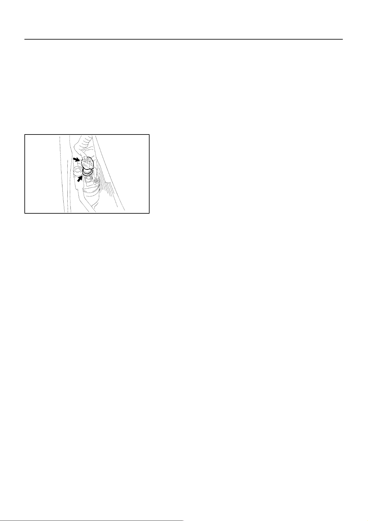
2. REMOVE PRESSURE SWITCH FROM LIQUID TUBE
Disconnect the connector and remove the pressure switch.
Torque: 10 N·m (100 kgf·cm, 7 ft·lbf)
HINT:
Lock the switch mount on the tube with an open end
wrench, being careful not to deform the tube, and remove
the switch.
At the time of installation, please refer to the following
item.
Lubricate a new O–ring with compressor oil and install the
switch.
1997 LEXUS ES300 (RM511U)
1649Author: Date:
Page 92

–AIR CONDITIONING PRESSURE SWITCH
INSTALLATION
Installation is in the reverse order of removal (See page AC–92 ).
AC–93
AC0BJ–01
1997 LEXUS ES300 (RM511U)
1650Author: Date:
Page 93
AC–94
3
–AIR CONDITIONING RELAY
5
4
3
4
5
RELAY
INSPECTION
AC2T0–01
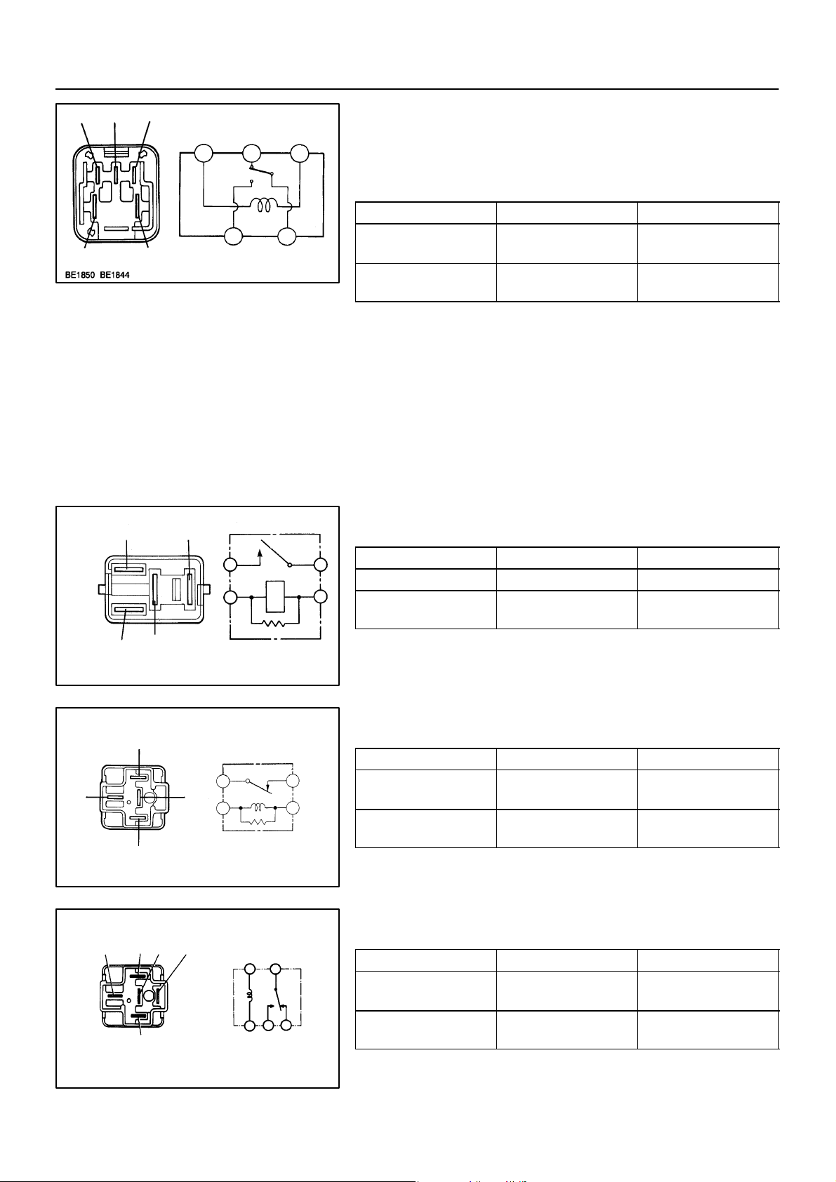
1. INSPECT HEATER MAIN RELAY
(Marking: HTR RLY) CONTINUITY
Condition Tester connection Specified condition
21
21
Z19533
Constant
Apply B+ between
terminals 3 and 5.
2 – 4
1 – 3
1 – 2 Continuity
Continuity
If continuity is not as specified, replace the relay.
2. INSPECT MAGNETIC CLUTCH RELAY
2
1
3
5
1
3
2
5
Z18060
(Marking: MG CLT RLY) CONTINUITY
Condition Tester connection Specified condition
Constant 1 – 2 Continuity
Apply B+ between
terminals 1 and 2.
3 – 5 Continuity
If continuity is not as specified, replace the relay.
3. INSPECT No.1 COOLING FAN RELAY
1
3
3
4
1
4
2
2
Z12319
(Marking: FAN RLY NO.1) CONTINUITY
Condition Tester connection Specified condition
Constant
Apply B+ between
terminals 1 and 2.
1 – 2
3 – 4
3 – 4 No continuity
If continuity is not as specified, replace the relay.
Continuity
4. INSPECT No. 2 COOLING FAN RELAY
15
3
2
4
13
54
2
(Marking: FAN RLY NO.2) CONTINUITY
Condition Tester connection Specified condition
Constant
Apply B+ between termi-
nals 1 and 2
1 – 2
3 – 4
3 – 5 Continuity
Continuity
If continuity is not as specified, replace the relay
N02832
1997 LEXUS ES300 (RM511U)
1651Author: Date:
Page 94
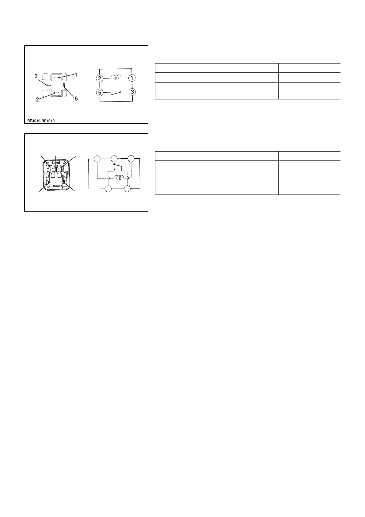
AC–95
–AIR CONDITIONING RELAY
5. INSPECT No.3 COOLING FAN RELAY
(Marking: FAN RLY NO.3) CONTINUITY
Condition Tester connection Specified condition
Constant 1 – 2 Continuity
Apply B+ between
terminals 1 and 2.
3 – 5 Continuity
If continuity is not as specified, replace the relay.
Z05932
6. INSPECT ENGINE MAIN RELAY
(Marking: ENGINE MAIN RLY) CONTINUITY
3
2
5
1
3
5
4
1
2
4
If continuity is not as specified, replace the relay.
Z06166
Condition Tester connection Specified condition
Constant
Apply B+ between
terminals 1 and 3.
1 – 3
2 – 4
4 – 5 Continuity
Continuity
1997 LEXUS ES300 (RM511U)
1652Author: Date:
Page 95
AC–96
–AIR CONDITIONING CONDENSER FAN
CONDENSER FAN
AC0BL–01
ON–VEHICLE INSPECTION
1. INSPECT CONDENSER FAN OPERATION
Inspect the fan operation, as shown in the chart below.
Test conditions:
Ignition switch ON
Blower speed control switch position ”HI”
Temperature control dial at ”MAX. COOL”
Install on manifold gauge set”
A/C switch ON
Condition Fan operation
Engine coolant temperature
83 °C (181 °F) or below
Engine coolant temperature
98 °C (208 °F) or above
Refrigerant pressure is less than
1,520 kPa (15.5 kgf/cm2, 220 psi)
Refrigerant pressure is 1,520 kPa
(15.5 kgf/cm2, 220 psi) or above
If operation is not as specified, proceed to the next inspection.
Not rotate
Rotate
Not rotate
Rotate
1997 LEXUS ES300 (RM511U)
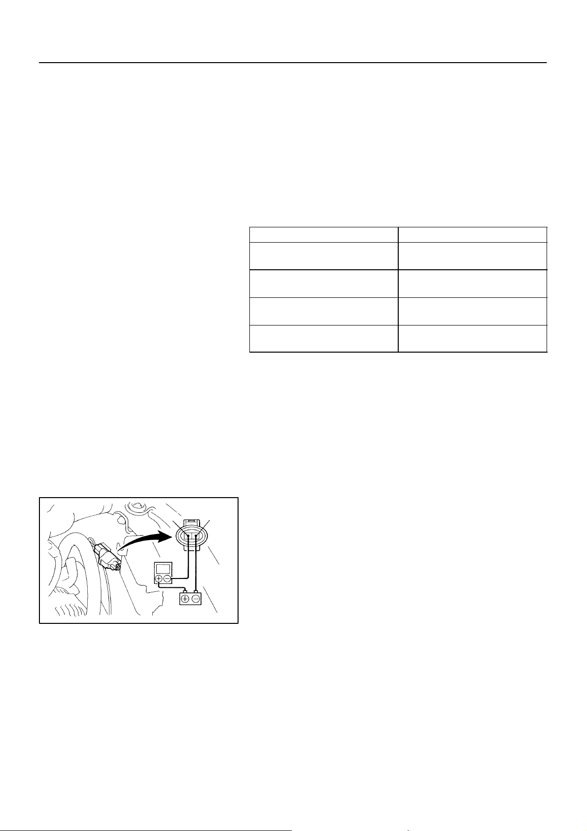
2. INSPECT CONDENSER FAN MOTOR OPERATION
1
2
(a) Disconnect the fan connector.
(b) Connect battery and ammeter.
(c) Check that the fan rotates smoothly, and then check that
the reading on the ammeter.
A
Specified amperage: 10.1 ± 1.8 A at 20 °C (68 °F)
If operation is not as specified, replace the fan motor.
If operation is as specified, check the pressure switch, cooling
N20290
fan relays and engine coolant temp. switch.
1653Author: Date:
Page 96
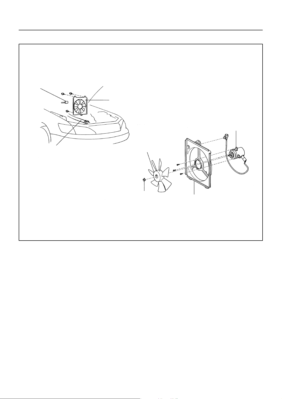
COMPONENTS
Condenser Fan Connector
AC–97
–AIR CONDITIONING CONDENSER FAN
AC0BM–01
Condenser Fan
Fan Motor
Upper Radiator Hose
Non–reusable part
Fan
Clip
Fan Shroud
Z19368
1997 LEXUS ES300 (RM511U)
1654Author: Date:
Page 97

AC–98
–AIR CONDITIONING CONDENSER FAN
REMOVAL
1. DRAIN ENGINE COOLANT FROM RADIATOR
HINT:
It is not necessary to drain out all the coolant.
2. DISCONNECT UPPER RADIATOR HOSE FROM RADIATOR
3. REMOVE CONDENSER FAN
(a) Disconnect the connector.
(b) Remove the 3 bolts and fan.
AC0BN–01
1997 LEXUS ES300 (RM511U)
1655Author: Date:
Page 98
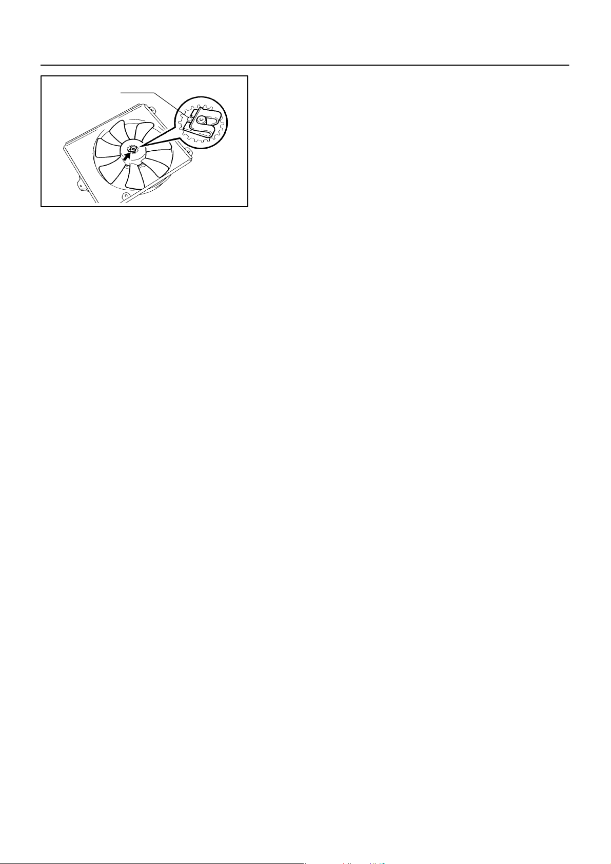
Protrusion
I03508
AC–99
–AIR CONDITIONING CONDENSER FAN
AC0BO–01
DISASSEMBLY
1. REMOVE FAN
Remove the clip and fan.
NOTICE:
When removing the clip and fan, do not apply too much
force to the motor shaft. And do not scratch the motor
shaft.
HINT:
At the time of installation, please refer to the following item.
Install a new clip from the side opposite the protrusion on the
fan.
2. REMOVE FAN MOTOR
(a) Disconnect the lead wire from the fan shroud.
(b) Remove the 3 screws and fan motor.
1997 LEXUS ES300 (RM511U)
1656Author: Date:
Page 99

AC–100
–AIR CONDITIONING CONDENSER FAN
REASSEMBLY
Reassembly is in the reverse order of disassembly (See page AC–99 ).
AC0BP–01
1997 LEXUS ES300 (RM511U)
1657Author: Date:
Page 100

–AIR CONDITIONING CONDENSER FAN
INSTALLATION
Installation is in the reverse order of removal (See pageAC–98 ).
AC–101
AC0BQ–01
1997 LEXUS ES300 (RM511U)
1658Author: Date:
 Loading...