

Page 1
C720
Setup Guide
November 2000
www.lexmark.com
Page 2

Edition: November 2000
The following paragraph does not apply to any country where such provisions are inconsistent with local law: LEXMARK INTERNATIONAL, INC.,
PROVIDES THIS PUBLICATION “AS IS” WITHOUT WARRANTY OF ANY KIND, EITHER EXPRESS OR IMPLIED, INCLUDING, BUT NOT
LIMITED TO, THE IMPLIED WARRANTIES OF MERCHANTABILITY OR FITNESS FOR A PARTICULAR PURPOSE. Some states do not allow
disclaimer of express or implied warranties in certain transactions; therefore, this statement may not apply to you.
This publication could include technical inaccuracies or typographical errors. Changes are periodically made to the information herein; these changes
will be incorporated in later editions. Improvements or changes in the products or the programs described may be made at any time.
Comments about this publication may be addressed to Lexmark International, Inc., Department F95/032-2, 740 West New Circle Road, Lexington,
Kentucky 40550, U.S.A. In the United Kingdom and Eire, send to Lexmark International Ltd., Marketing and Services Department, Westhorpe House,
Westhorpe, Marlow Bucks SL7 3RQ. Lexmark may use or distribute any of th e info rmation you supply in any way it believ es app ropr iate without
incurring any obligation to you. You can purchase additional copies of publications related to this product by calling 1-800-553-9727. In the United
Kingdom and Eire, call 0628-481500. In other countries, contact your point of purchase.
References in this publication to products, programs, or services do not imply that the manufacturer intends to make these available in all countries in
which it operates. Any reference to a product, program, or service is not intended to state or imply that only that product, program, or service may be
used. Any functionally equivalent product, program, or service that does not infringe any existing intellectual property right may be used instead.
Evaluation and verification of operation in conjunction with other products, programs, or services, except those expressly designated by the
manufacturer, are the user’s responsibility.
Lexmark and Lexmark with diamond design, MarkNet and MarkVision are trademarks of Lexmark International, Inc., registered in the United States
and/or other countries.
®
is a registered trademark of the Hewlett-Packard Company. PCL is Hewlett-Packard Company’s designation of a set of printer commands
PCL
(language) and functions included in its printer products. This printer is intended to be compatible with the PCL language. This means the printer
recognizes PCL commands used in various application programs, and that the printer emulates the functions corresponding to the commands.
®
PostScript
(language) and functions included in its software products. This printer is intended to be compatible with the PostScript 3 language. This means the
printer recognizes PostScript 3 commands used in various application programs, and that the printer emulates the functions corresponding to the
commands.
Other trademarks are the property of their respective owners.
© Copyright 2000 Lexmark International, Inc.
All rights reserved.
UNITED STATES GOVERNMENT RESTRICTED RIGHTS
This software and documentation are provided with RESTRICTED RIGHTS. Use, duplication or disclosure by the Government is subject to restrictions
as set forth in subparagraph (c)(1)(ii) of the Rights in Technical Data and Computer Software clause at DFARS 252.227-7013 and in applicable FAR
provisions: Lexmark International, Inc., Lexington, KY 40550.
is a registered trademark of Adobe Systems Incorporated. PostScript 3 is Adobe Systems’ designation of a set of printer commands
Safety information
• If your product is NOT marked with this symbol , it MUST be connected to an electrical outlet that is properly grounded.
• The power cord must be connected to an electrical outlet that is near the product and easily accessible.
• Refer service or repairs, other than those described in the operating instructions, to a professional service person.
• This product is designed, tested, and approved to meet strict global safety standards with the use of specific Lexmark components.
The safety features of some parts may not always be obvious. Lexm ark is not responsible f o r the use of other replacem en t parts.
• Y our product uses a laser , exercise CAUTION: Use of controls or adjustments or performance of procedures other than those specified
herein may result in hazardous radi ation exposure.
• Y ou r product uses a printing process that heats the print media, and the heat may cause the media to release emissions. Yo u must
understand the section in your operating instructions that discusses the guidelines for selecting print media to avoid the possibility of
harmful emissions.
FCC compliance
• This device complies with Part 15 of the FCC Rules for a Class B (without network) or Class A (with network) digital device. Refer to
Notices on the Lexmark C720 online infor m ation for further information.
Page 3

Table of contents
Using your documentation . . . . . . . . . . . . . . . . . . . . . . . . . . . . . . . . . . . . . . . .1
Step 1: Select a location for your printer . . . . . . . . . . . . . . . . . . . . . . . . . . . . 3
Step 2: Unpack and position the optional drawer . . . . . . . . . . . . . . . . . . . . .7
Step 3: Unpack and position the printer . . . . . . . . . . . . . . . . . . . . . . . . . . . . 9
Step 4: Set up the optional drawer . . . . . . . . . . . . . . . . . . . . . . . . . . . . . . . . 15
Step 5: Install memory and network options . . . . . . . . . . . . . . . . . . . . . . . .23
Step 6: Install the optional duplex unit . . . . . . . . . . . . . . . . . . . . . . . . . . . . . 43
Step 7: Install supplies . . . . . . . . . . . . . . . . . . . . . . . . . . . . . . . . . . . . . . . . . . 49
Step 8: Attach the cables . . . . . . . . . . . . . . . . . . . . . . . . . . . . . . . . . . . . . . . .61
Step 9: Load the paper tray . . . . . . . . . . . . . . . . . . . . . . . . . . . . . . . . . . . . . . 65
Step 10: Verify setup . . . . . . . . . . . . . . . . . . . . . . . . . . . . . . . . . . . . . . . . . . . . 75
Step 11: Load MarkVision and drivers . . . . . . . . . . . . . . . . . . . . . . . . . . . . . . 89
Step 12: Configure the network printer . . . . . . . . . . . . . . . . . . . . . . . . . . . . .91
Index . . . . . . . . . . . . . . . . . . . . . . . . . . . . . . . . . . . . . . . . . . . . . . . . . . . . . . . .109
iii
Page 4

iv
Page 5

Using your
documentation
About this book This Setup G uide contains all the info rmation you need to
TM
C720 color lase r printer. This
Note: Refer to the safety infor-
mation in the front of this book
before setting up your printer.
set up your new Lexmark
manual provides detailed instructions for unpacking your
printer, installing options, lo ading paper or media in the
trays, and launching the CD to install printer drivers and
utilities.
When you have completed setup and if you need more
information about your pri nter, refer to the Lexmark C720
online information either on the Publications CD or on the
Lexmark Web site at www.lexmark.com. Information is
available on printer settings, color functions, media specifications, printer supplies, memory requirements, and
solving printer problems.
Lexmark offers other sources of information about your
printer or about Lexmark products and services. The Driv-
ers, MarkVision and Utilities compact disc (CD) that comes
with your printer contains several online documents. You
can also access our site on the World Wide Web, www.lexmark.com.
Using your documentation
1
Page 6
Conventions It may help you to recognize the conventions we
have used in this book:
• Operator panel buttons are printed in a
boldface type. For example:
Go after chan ging a menu setting.
Press
• Messages that appear on the operator panel
display are also prin ted in a boldface t ype:
88 Black Toner Low appears on the oper-
If
ator panel display, you should order a
new black toner cartridge at this ti me.
Note: A note provides auxiliary infor-
mation you may find useful.
Warning! A warning identifies some-
thing that might damage your printer
hardware or software.
CAUTION! A caution identifies some-
thing that might cause you harm.
Use the table to locate
your next step.
• Notes, warnings, and cautions appear i n the
left column for easy reference.
• On selected pages, steps you may skip, or
information about steps you may need to
perform are identified with a colored arrow
and table.
If you need to… See page…
Determine the space requ irements for you r
printer
Unpack and position the optional drawer
unit
Unpack and position the printer 9
3
7
2
Using your documentation
Page 7

Step 1: Select a location
for your printer
Choosing the correct location for your new Lexmark C720 printer is vital to ensuring the printer
provides you with the quality of service you
expect.
When selecting a place to set up your printer consider:
• The amount of space your printer and any
options will require
• The type of environment necessary for opti-
mum printer performance
Allowing enough
space
Allow enough space for the printer and any
options you m ay have purchase d.
Leave enough room to open the printer’s p a per
trays and top and rear doors. Allow space for
proper venting around the printer.
Select a location for your printer
3
Page 8
102 mm
(4 in.)
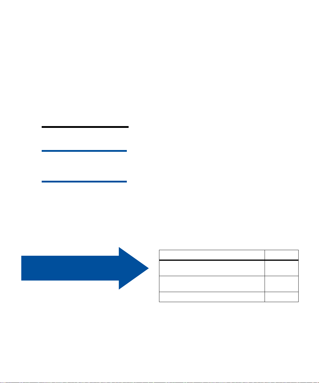
For a base printer
When selecting a location for your printer, make
sure you have at least the amount of space indicated in the figure at left.
710 mm
(28 in.)
203 mm
(8 in.)
1110 mm
(44 in.)
102 mm
(4 in.)
1110 mm
(44 in.)
508 mm
(20 in.)
711 mm
(28 in.)
1434 mm
(57 in.)
For a printer with an
optional paper drawer
508 mm
(20 in.)
711 mm
(28 in.)
862 mm
(34 in.)
203 mm
(8 in.)
1434 mm
(57 in.)
When selecting a location for your printer configured with an opt ional 500-sheet drawer, make sure
you have at least the amount of space indicated in
the figure at left.
Select a location for your printer
4
Page 9
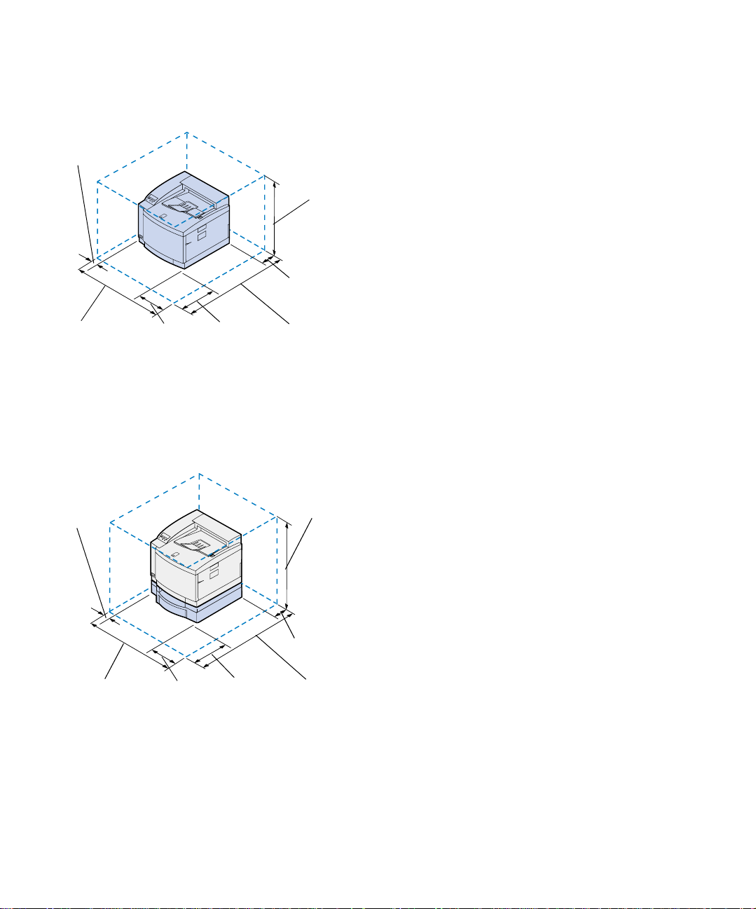
For a printer with an
optional paper drawer a nd
duplex unit
102 mm
(4 in.)
1110 mm
(44 in.)
508 mm
(20 in.)
711 mm
(28 in.)
Considering
environmental issues
912 mm
(36 in.)
711 mm
(28 in.)
1434 mm
(57 in.)
When selecting a location for your printer configured with an optional 500-sheet drawer and
duplex unit, make sure you have at least the
amount of space indicated in the figure at left.
When choosing a place to set up the printer, make
sure the location you select is:
Note: Adequate ventilation is espe-
cially important if you will be printing a
high volume of materials, or if the printer
will be used continuously over a long
period of time.
• A firm, leve l, and stable surfac e
• Well ventilated
• Away from the direct airflow of air condi-
tioners, heaters, or ventilators
• Free of temperature or humidity extremes
or fluctuations
• Clean, dry, and free of dust
• Away from direct sunlight
Select a location for your printer
5
Page 10
Moving the printer In the future if you’re going to move the printer,
remember the following:
• The printer weighs approximately 39 kg (86
lb) and two people are required to lift it
safely.
• When lifting, use the handholds on the
sides.
• Remove the toner cart ridges, photo devel-
oper cartridge, and oil bottle before you
move the printer. Remove the oil from the
oil sump after removing the oil bottle.
• Protect the photo developer cartridge from
light by covering it with a cloth.
• Unlock the optional paper drawer from the
printer by removing the rear locking clip
and sliding the front lock to the left.
• Be sure to plug the printer into a properly
grounded outlet.
Use the table to locate
your next step.
Select a location for your printer
6
If you need to… See page…
Unpack and position the opt ion al drawer 7
Unpack and position the printer 9
Page 11
Step 2: Unpack and position
the optional drawer
Your printer supports an optional drawer with a
single 500-sheet tray. To install the optional
drawer:
CAUTION! If you are installing the
optional drawer after initial printer setup,
turn the printer off, and disconnect the
power cord and printer cables.
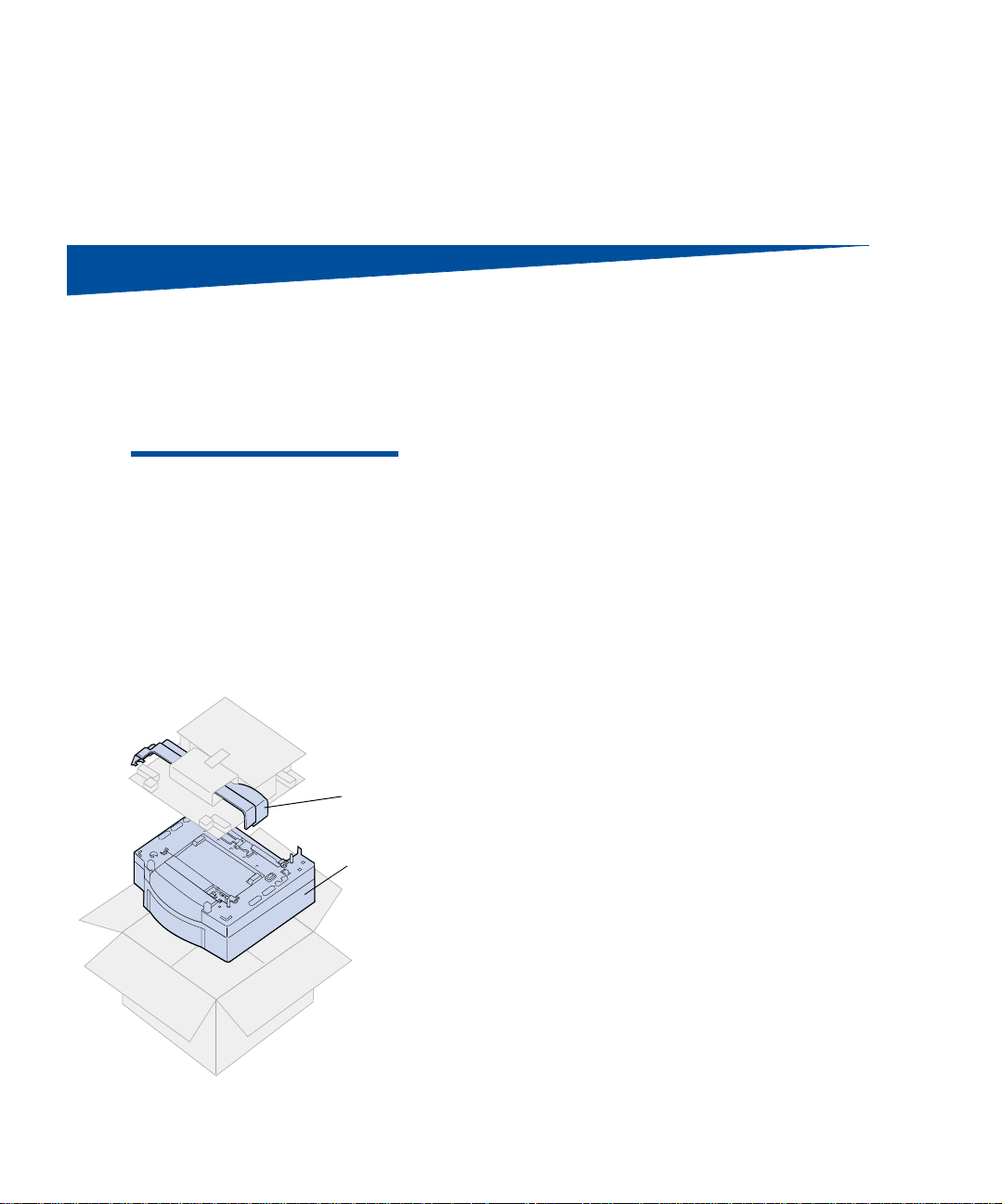
Side access
panels
Optional drawer
1 Remove the optional drawer and side
access panels from the carton.
Save the carton and packing material in case
you need to repack the drawer.
If any items are missing or damaged, refer
to th e registration card for the Lexmark
phone number for your country.
2 Remove an y shipping tape and packing
material from the drawer and tray.
3 Place the side access panels to the side.
Unpack and position the optional drawer
7
Page 12
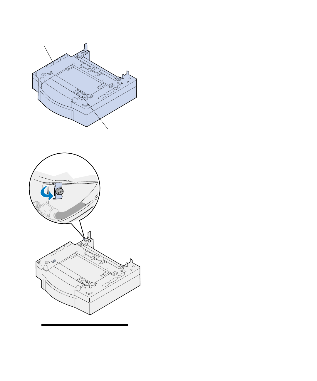
Optional drawer base
4 Place the optional drawer in the location
you have selected for your printer.
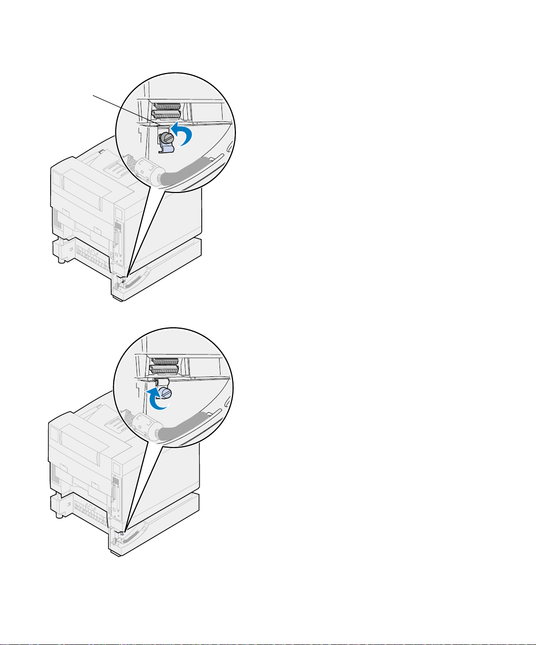
Lock
5 Loosen the locking clip thumbscrew by
rotating counterclockwise.
6 Rotate the locking clip so that it hangs
down.
Rotating the locking clip down prevents
damage to the connector cover and makes
cover removal easier.
Note: Install the side access panels
after the optional drawer or duplex unit
electrical connections are made.
Unpack and position the optional drawer
8
Page 13
Step 3: Unpack and position
the printer
CAUTION! This printer weighs 39 kg
(86 Ib) and requires two people to lift it.
Anytime you move or lift the printer make
sure you have someone help you. Whenever you lift the printer use the handholds located on the sides.
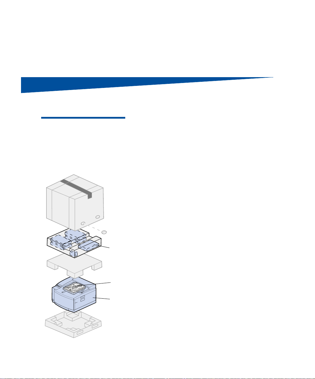
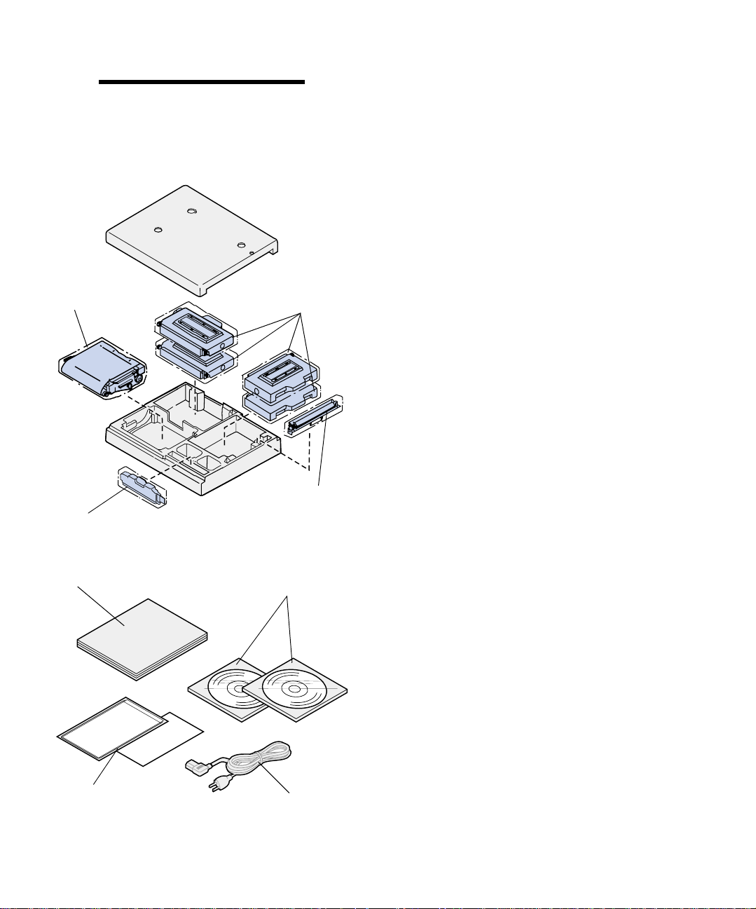
1 Remove the supplies box and accessories bag
from the printer carton.
Save the pri nter carton and packing materials in case you need to repack the printer.
Supplies box
Accessories
bag
Printer
Unpack and position the printer
9
Page 14
Note: Do not remove the oil bottle,
photo developer, or toner cartridges from
their individual packages until you are
ready to use them.
Photo developer cartridge
Oil bottle
Toner cartridges
2 Open the supplies box and make sure you
have the following items:
– Cleaning roll
– Photo developer cartridge
– Black, magenta, cyan, and yellow toner
cartridges
– Oil bottle
Cleaning
roll
Setup guide
Quick Reference Card
and Sleeve
Unpack and position the printer
10
CD’s
Power cord
3 Open the accessories bag and make sure
you have the following items.
– Setup Guide and Quick Reference Card
– Publications CD
– Drivers, MarkVision and Utilities CD
– Power cord
If any items are missing or damaged, refer
to th e registration card for the Lexmark
phone number for your country.
In addition to the Publications CD, you can
access your C720 online information on our
site on the World Wide Web at www.lexmark.com. There you can obtain up-to-date
Page 15
Note: Place the printer in an area that
will be convenient for removing the packing material and installing the components.
Position the printer If you have an option al dr awer f ollo w the “Printer
Printer with optional
drawer
information about Lexmark and Lexmark
products.
with optional drawer” procedures. Otherwise go
follow the “Printer without optional drawer” procedures on page 13.
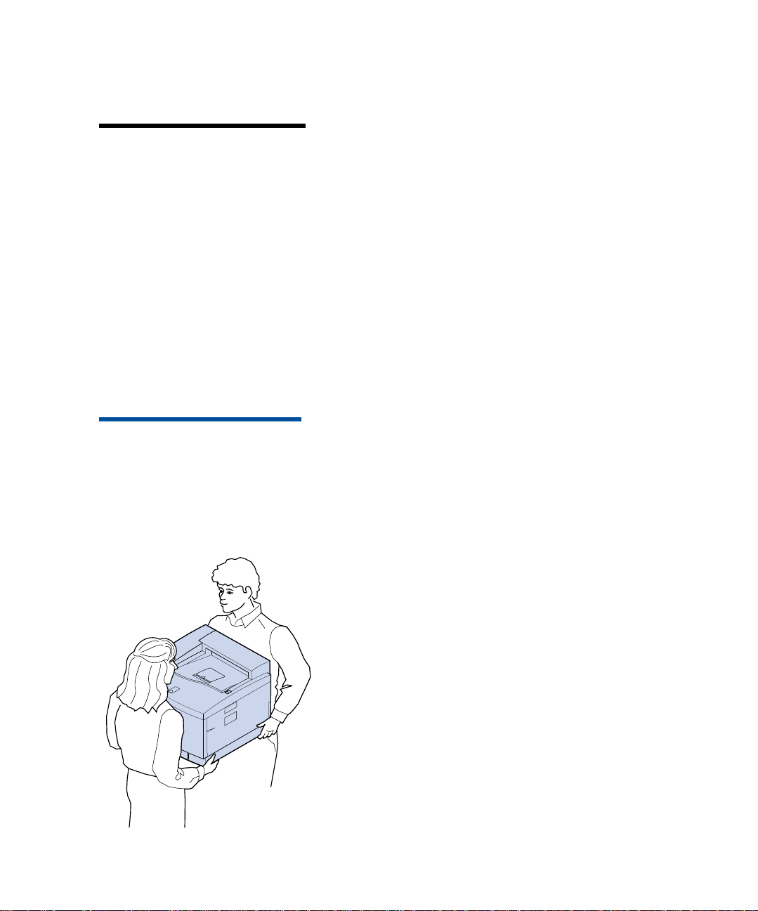
CAUTION! This printer weighs 39 kg
(86 Ib) and requires two people to lift it.
Anytime you move or lift the printer make
sure you have someone help you. Whenever you lift the printer use the handholds located on the sides of the printer.
1 Have someone help you lift the printer
from the carton base.
When lifting, use the handholds on the
sides.
Unpack and position the printer
11
Page 16
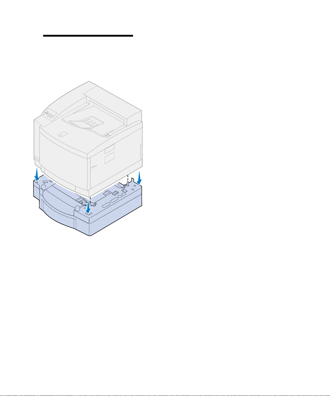
Note: If you align the sides and cor-
ners of the printer with the optional
drawer and then lower the printer, the
pins and connector align easier.
2 Align the pins on top o f the optional
drawer with the holes on the bottom of the
printer.
3 Lower the printer onto the drawer.
4 Remove the shipping tape and other pack-
ing material from the exterior of the
printer.
5 Continue with “Iden tifying printer parts”
on page 14.
Unpack and position the printer
12
Page 17
Printer without optional
drawer
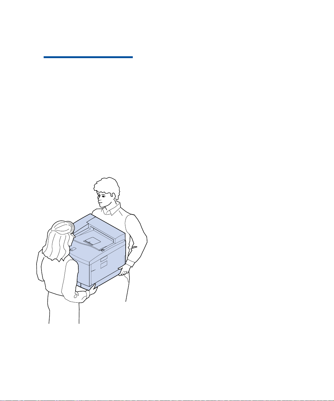
CAUTION! This printer weighs 39 kg
(86 Ib) and requires two people to lift it.
Anytime you move or lift the printer make
sure you have someone help you. Whenever you lift the printer use the handholds located on the sides of the printer.
1 Have someone help you lift the printer
from the carton base.
When lifting, use the handholds on the
sides.
2 Place the printer on a flat, stable surface
that will be convenient for removing the
packing material and insta l ling any
options.
3 Remove the shipping tape and other pack-
ing material from the exterior of the
printer.
4 Continue with “Iden tifying printer parts”
on page 14.
Unpack and position the printer
13
Page 18
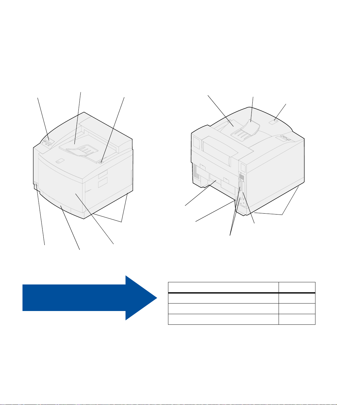
Identifying printer
parts
Familiarize yourself with the names and locations
of items on your new printer. This will help you
during printer setup. We use the same terms
throughout this book, the Publications CD and on
the Lexmark C720 online information.
Operator panel
Pow er switch
Top door
Paper tray
Top door release latch
Handholds
Front door
Top door and output bin
Rear door
Power cord socket
Paper guide
Paper stop
Handholds
Option slot cover
Parallel and Ethernet
connectors
Use the table to locate
your next step.
Unpack and position the printer
14
If you need to… See page…
Set up the optional d rawer 15
Install memory and network options 23
Install supplies 49
Page 19
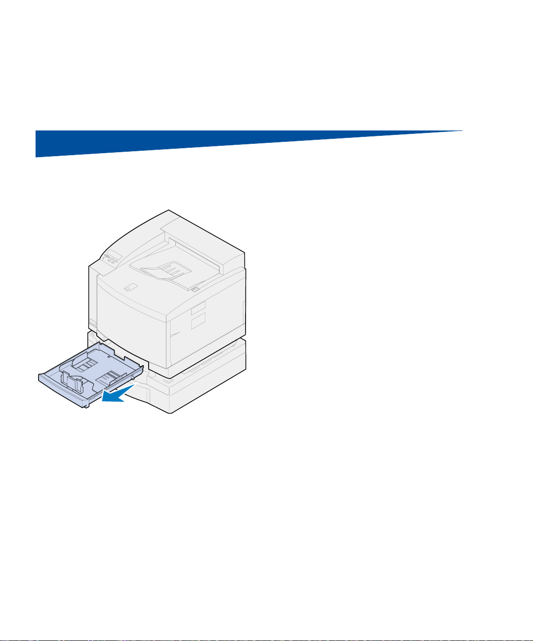
Step 4: Set up the optional
drawer
1 Remove tray 1.
Set up the optional drawer
15
Page 20
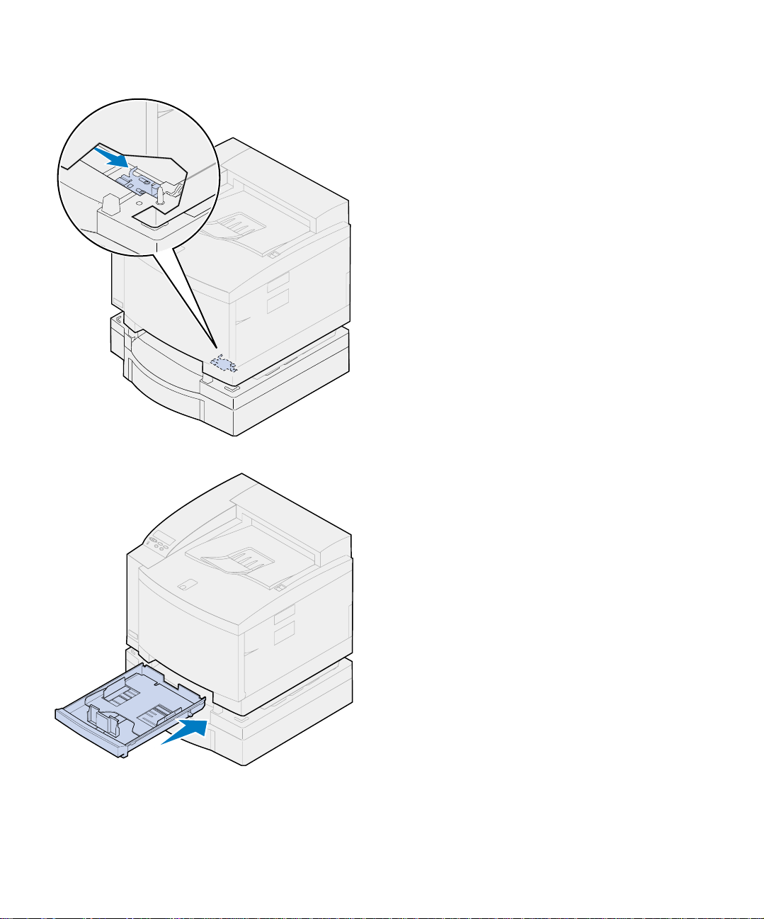
2 Move the drawer unit lo ck to the right
until it locks into place.
The lock is located between the optional
drawer and printe r. Y ou must r eac h thr ough
the printer tray opening to move the lo ck.
3 Slide in the paper tray.
Set up the optional drawer
16
Page 21
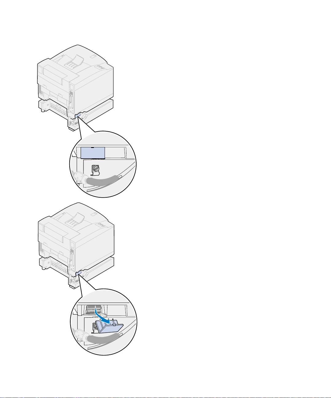
4 Remove the connector cover.
The connector cover is located as shown.
Press in and rotate the cover dow nward or
use a small flathead screwdriver to remove
the connector cover.
Set up the optional drawer
17
Page 22
Slot
5 Make sure the locking clip thumbscrew is
loose enough to rotate the locking clip.
6 Rotate the locking clip and place the t op of
the clip inside the slot.
7 Tighten the locking clip thumbscrew.
Set up the optional drawer
18
Page 23
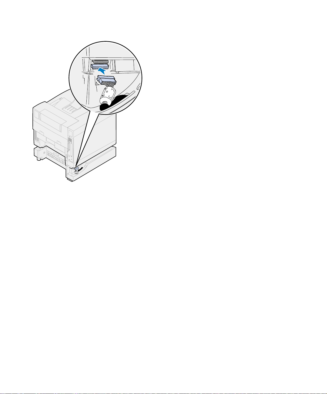
8 Align and attach the white drawer connec-
tor to the white printer connector.
9 If you have an optional duplex unit skip
steps 10 and 1 1. Locate yo ur next step u sing
the table on page 21.
Set up the optional drawer
19
Page 24
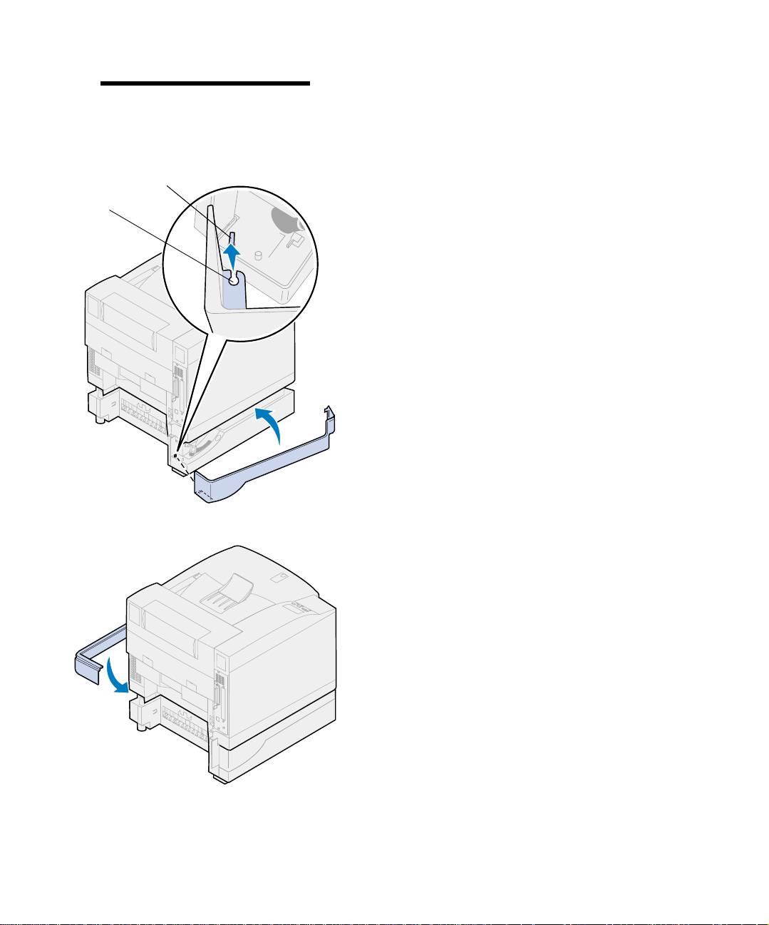
Note: Do not install the side access
panels at this time if you have a duplex
unit.
Pin
Slot
10 Install the left side access panel.
a Place the slot on the rear of the panel
onto the pin at the rear of the printer.
b Rotate the panel toward the front of the
printer until it snaps into place.
Set up the optional drawer
20
11 Install the right side access panel.
a Place the rear of the panel into the rear
of the printer.
b Rotate the panel toward the front of the
printer until it snaps into place.
If you installed the optional drawer after
initial printer setup, connect the printer
cables and power cord, and then turn the
printer on.
Page 25
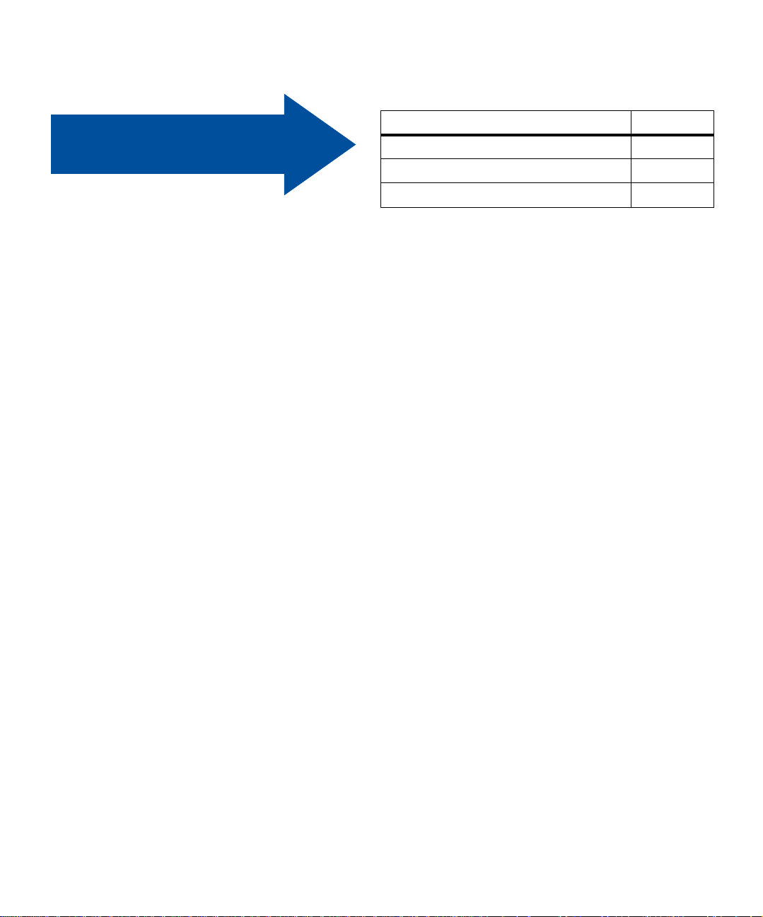
Use the table to locate
your next step.
If you need to… See page…
Install the memory or network options 23
Install the optional duplex unit 43
Install supplies 49
Set up the optional drawer
21
Page 26

Set up the optional drawer
22
Page 27

Step 5: Install memory and
network options
You can add memory and interface ports to your
printer by installing the following options:
• Printer memory
• Hard disk
• Print server (INA)
• Tri-Port adapter
• Parallel port interface card
• USB port interface card
Removing the
system board
Note: Place the printer in a convenient
location to remove the system board for
installing internal opt ions.
CAUTION! This printer weighs 39 kg
(86 Ib) and requires two people to lift it.
Anytime you move or lift the printer make
sure you have someone help you. Whenever you lift the printer use the handholds located on the sides.
You must remove the system board to install
memory cards, a hard disk, print server, tri-port
adapter, or a parallel port interface card.
You need a number 2 Phillips screwdriver to
remove the system board.
Install memory and network options
23
Page 28
CAUTION!If you are installing internal
options after initial printer setup, turn the
printer off and unplug the power cord. If
you have any other devices connected to
the printer, turn them off as well and
unplug any cables going to the printer.
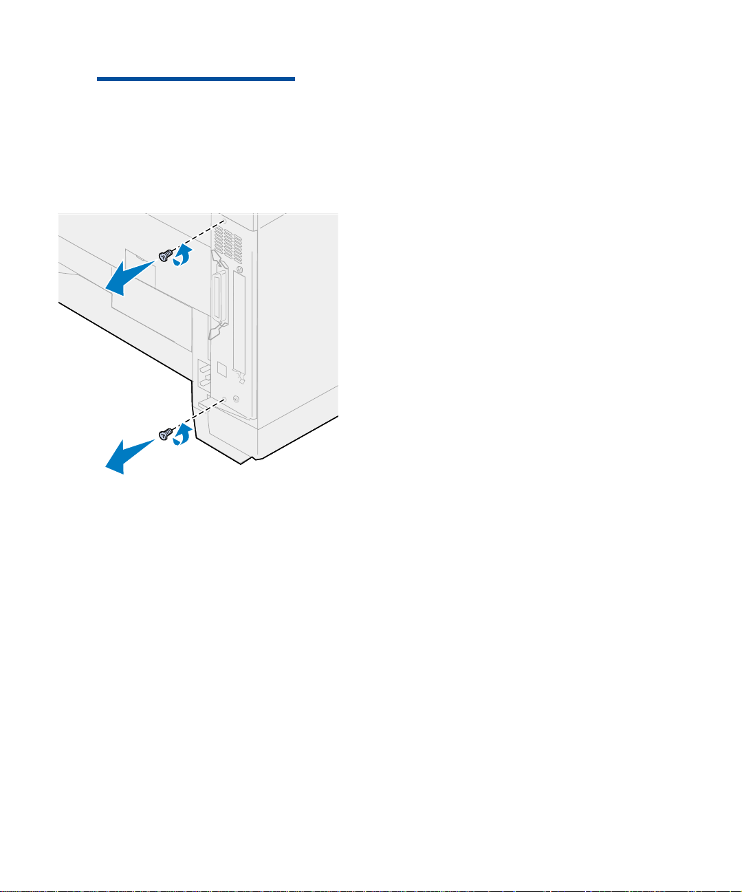
1 Remove the two screws on the system
board cover as shown.
Put the screws in a safe place so they are
available when you reinstall the system
board.
Install memory and network options
24
Page 29
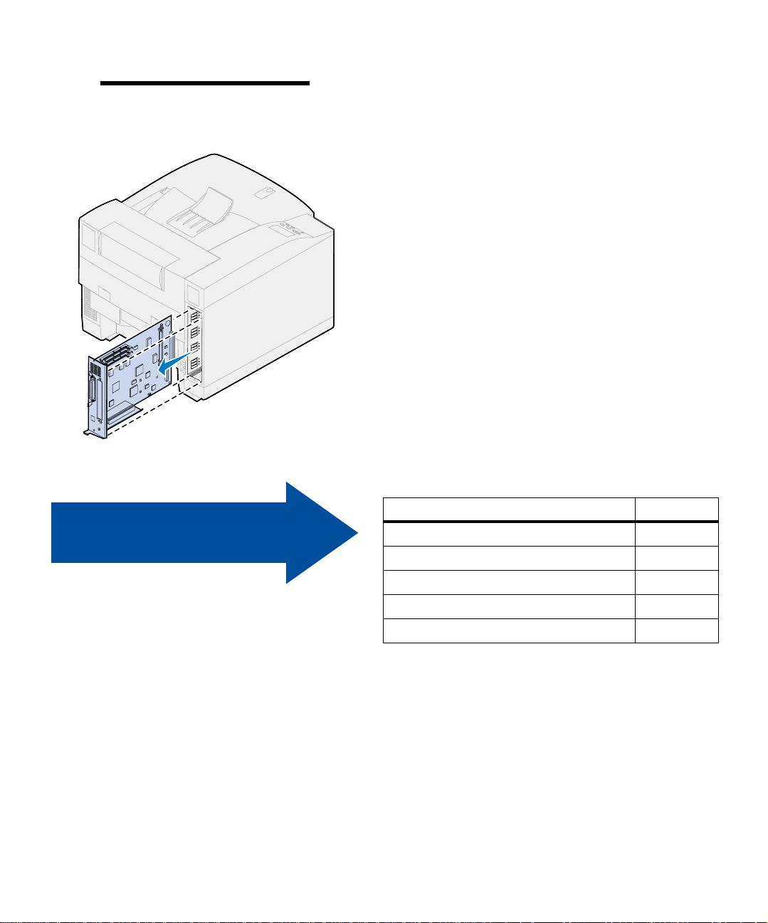
Note: You must replace the system
board before you can operate the printer.
2 Pull the syst em board out of the printer.
Use the table to locate
your next step.
If you need to… See page…
Install a memory card 26
Install a flash memory card 29
Install a hard disk 33
Install a printer option card 37
Install the system board 39
Install memory and network options
25
Page 30
Installing memory
cards
Note: Memory options designed for
other Lexmark printers may not work
with your printer. For more information,
refer to the Lexmark C720 online information.
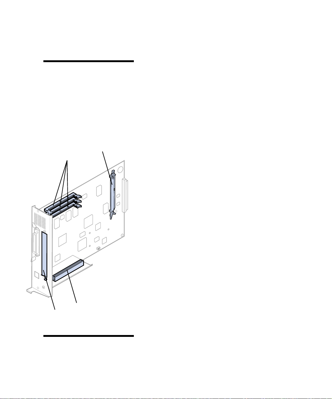
Resident code card
DO NOT REMOVE
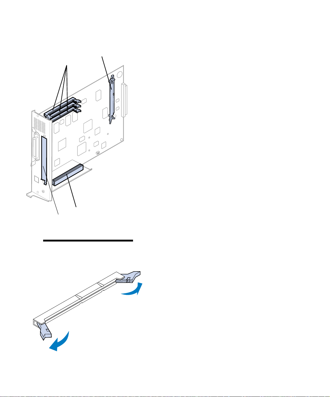
Memory connectors
Your printer comes with at least 32MB already
installed. (Some printer mode ls may have more
standard memory.) You can purchase many different memory options from Lexmark for the three
memory connectors in your printer. The maximum amount of usable memory is 384MB. Use
SDRAM DIMM memory cards that meet the following criteria:
• 100MHz or greater
• 100 pin
• 4K refresh rate
• Unbuffered, non ECC
• x32
• 3.3 V
If you need to remove a memory card, refer to the
Lexmark C720 online information.
To install optional memory:
1 Complete the steps in “Removing the
system board” on page 23 if the system
board is still installed.
2 Locate the memory connectors on the sys-
tem board.
Option slot
Option slot cover
Note: Your printer may not have a resi-
dent code card.
Install memory and network options
26
Each connector can support either a printer
memory card or a flash memory card.
You cannot operate the printer with more
than one flash memory card installed.
Page 31

Warning! The memory card is easily
damaged by static electricity. Touch
something metal before you touch the
memory card.
3 Open the latches on both ends of the con-
nector socket you are going to use.
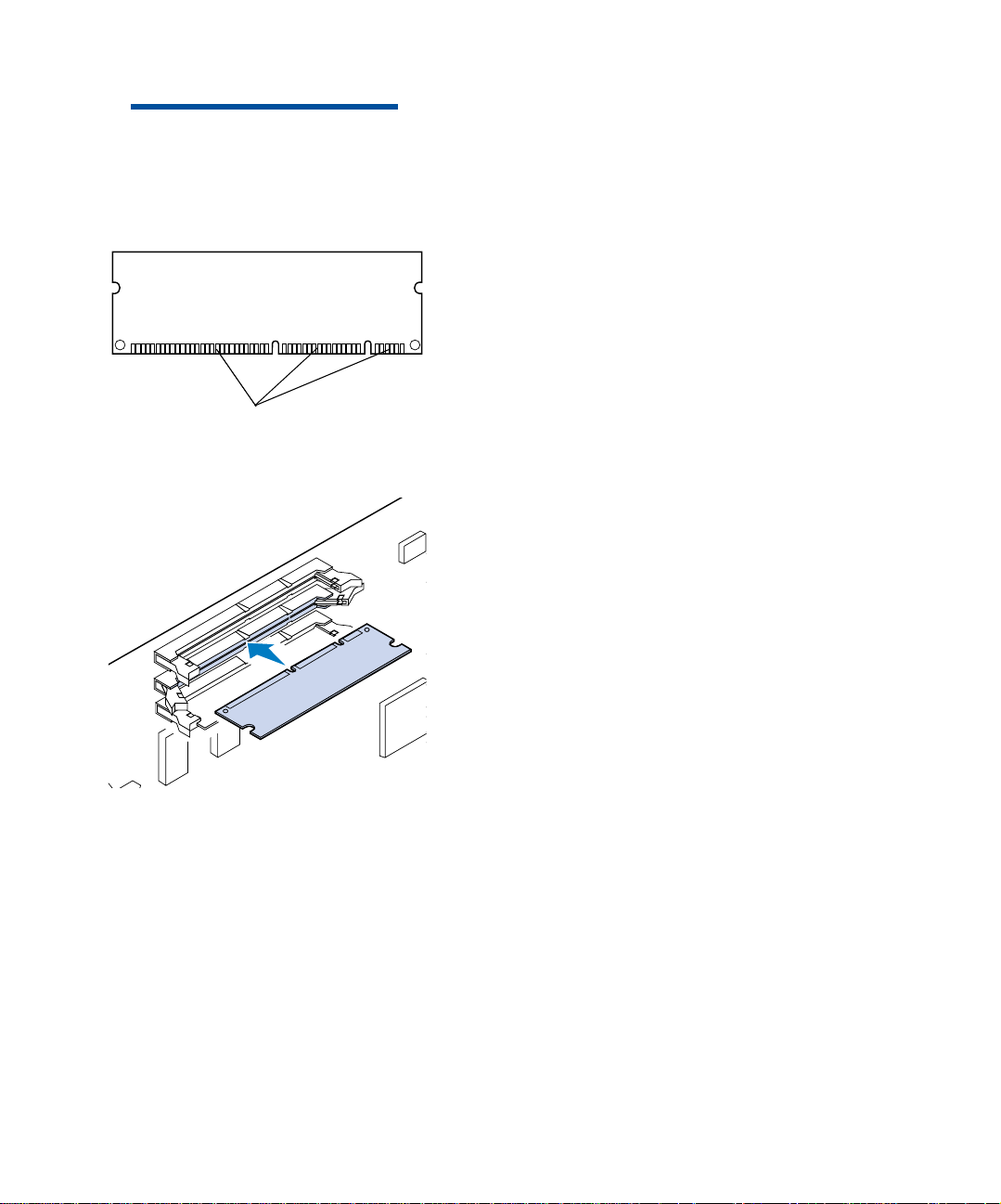
4 Unpack the memory card.
Unpack each memory card separately just
before installing it. Avoid touching connection points along the edge of card. Save the
packaging.
Connection points
5 Hold the memory card with the co nnection
points pointing toward the system b oa rd
as shown.
Install memory and network options
27
Page 32
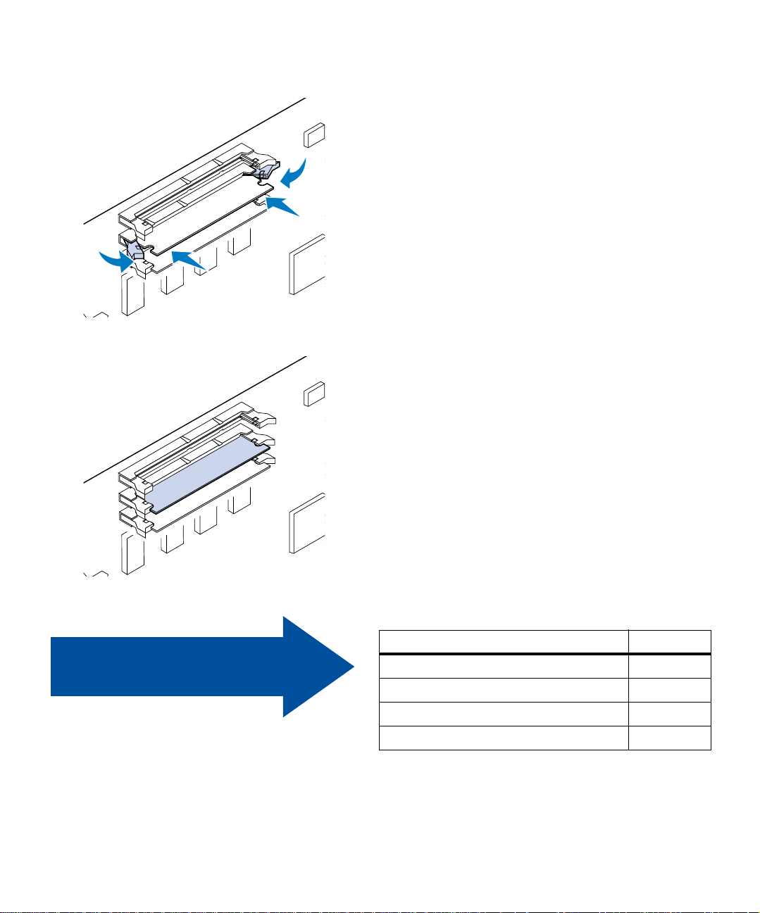
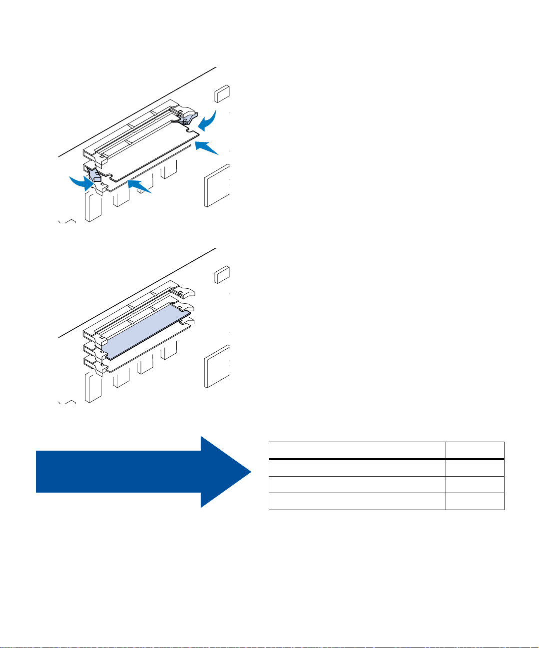
6 Push the memory card into the connector
until the latches on both ends of the connector snap into place.
It may require some force to fully seat the
card.
7 Make sure the latches fit over the not che s
on each end of the connector card.
8 Repeat steps 3 throug h 7 to install other
memory cards.
Use the table to locate
your next step.
Install memory and network options
28
If you need to… See page…
Install a flash memory card 29
Install a hard disk 33
Install a printer option card 37
Install the system board 39
Page 33

Flash memory option Flash memory is useful for stori ng information
such as downloaded fonts and macros. Your
printer driver or the MarkVision
used to download fonts, symbol sets, and macros
to flash memory.
TM
utility can be
Note: You cannot operate the printer
with more than one flash memory card
installed.
Installing a flash memory
card
Note: Each connector can support
either a printer memory card or a flash
memory card. Installing a flash memory
card reduces your maximum RAM memory capability.
Information stored in flash memory is retained
when the printer is turned off. You can buy 2MB,
4MB, 8MB, or 16MB flash memory cards.
Refer to the Technical Reference for more details
about using your flash memory option.
If you need to remove a flash memory card, refer
to the Lexmark C720 online information.
1 Complete the steps in “Removing the
system board” on page 23 if the system
board is still installed.
Install memory and network options
29
Page 34
Resident code card
DO NOT REMOVE
Memory connectors
Option slot
Option slot cover
2 Locate the memory connectors on the sys-
tem board.
Each connector can support either a printer
memory card or a flash memory card.
Note: Your printer may not have a resi-
dent code card.
Install memory and network options
30
3 Open the latches on both ends of the con-
nector socket you are going to use.
Each connector can support either a printer
memory card or flash memory card.
You cannot operate the printer with more
than one flash memory card installed.
Page 35
Warning! The flash memory card is
easily damaged by static electricity.
Touch somethin g meta l bef or e y ou touc h
the memory card.
Connection points
4 Unpack the flash memory card.
You can install a 2MB, 4MB, 8MB, or 16MB
flash memory card.
Unpack the flash memory card just before
installing it. Avoid touching connection
points along the edge of car d. Save the pa ckaging.
5 Hold the flash memory card with the con-
nection points pointing toward the sy st em
board as shown.
Install memory and network options
31
Page 36
6 Push the flash memory card into the co n-
nector until the latches on both ends of the
connector snap into place.
It may require some force to fully seat the
card.
7 Make sure the latches fit over the not che s
on each end of the connector card.
Use the table to locate
your next step.
Install memory and network options
32
If you need to… See page…
Install a hard disk 33
Install a printer option card 37
Install the system board 39
Page 37
Installing a hard disk You can purchase a hard disk option from Lex-
Warning! System board electrical com-
ponents are easily damaged by static
electricity. Touch something metal before
you touch any system board electronic
components or connect or s.
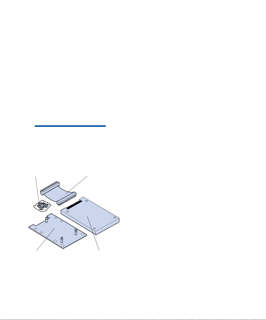
Attachme nt screws
Ribbon cable
mark. You must assemble the hard disk option
and attach it to the system board.
If you use a third-part y hard di sk, it must meet the
following cr iteria:
• 2.5-inch platter
• ATA-2 (IDE) interface
• Maximum thickness of 13 mm (0.51 in.)
• 3.2GB minimum hard disk capacity
• 10GB maximum hard disk capacity
You need a number 2 Phillips screwdriver to
attach the hard disk to the mounting pla te.
1 Complete the steps in “Removing the
system board” on page 23 if the system
board is still installed.
Mounting plate
Hard disk
Place the system board on a flat, level, and
stable surface.
2 Remove the mounting plate, hard disk,
ribbon cable, and attachment screws from
the package.
Install memory and network options
33
Page 38
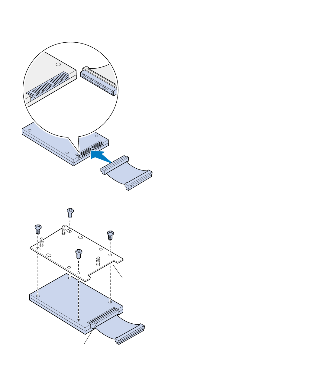
3 Align the ribbon cable connec tor to the
connector pins on the hard disk.
The connector ends on the ribbon cable
slightly differ from each other. The connector end that has pin holes not drilled is the
connector that attaches to the hard disk.
4 Push the cable connector onto the hard
disk.
5 Align the screw holes in the hard disk with
the holes on the mounting plate.
Hard disk connector
Install memory and network options
34
Notch
Make sure the hard disk connector and
notch on mounting plate are aligned as
shown.
6 Insert the four screws into the holes on the
mounting plate.
7 Gently tighten the screws to secure the
hard disk to the mounting plate.
Page 39
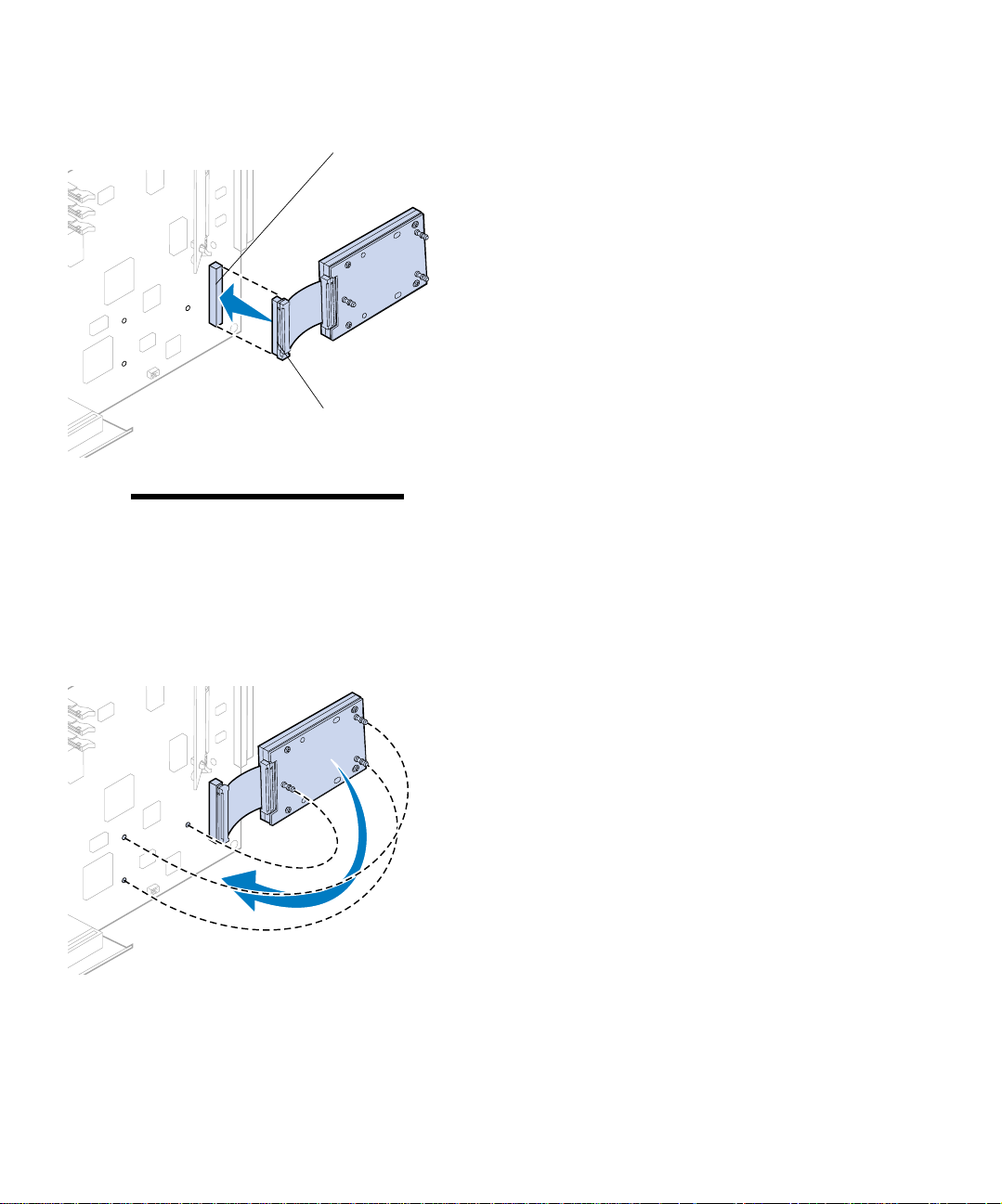
System board connector
Hard disk connector
Note: If the holes on the mounting
plate do not align with the holes on the
system board, the mounting plate has
been incorrectly installed on the hard
disk. Refer to step 5 on page 34 for
proper mounting plate installation.
8 Align the connector on th e rib bo n ca ble
with the connector pins on the system
board.
9 Press the hard disk cable connector onto
the system board connector.
10 Rotate the hard disk and mounting plate as
shown to align the three posts on the
mounting plate with the holes on the system board.
Install memory and network options
35
Page 40
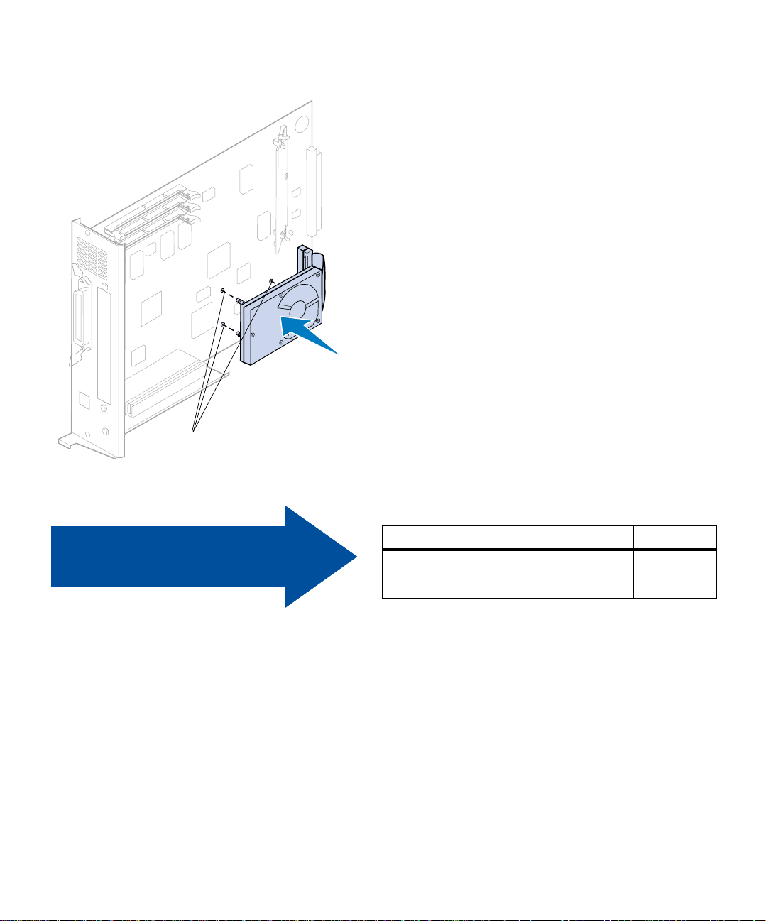
Mounting holes
11 Press the mounting plate posts into the
three holes on the system board until they
snap into place.
Use the table to locate
your next step.
Install memory and network options
36
If you need to… See page…
Install a printer option card 37
Install the system board 39
Page 41
Installing printer
option cards
You can install any of the following printer option
cards in your printer:
• Print server
• Tri-Port adapter
• Parallel port interface card
• USB interface card
A print server (sometimes called an internal network adapter or INA) such as the
MarkNet
a local area network (LAN). MarkNet N2000 print
servers support the following LAN options:
The tri-Port adapter provides connectors for the
following:
The parallel port interface card provides an additional parallel port. Its IEEE 1284C connector
requires a 1284 A–C cable. You can purchase a 3 m
(9.8 ft) cable, Lexmark part number 43H5171,
meeting these specifications. Refer to the documentation that came with your interface card or
adapter for more information.
TM
N2001e lets you connect th e printer to
• Ethernet 10BaseT and 10Base2
• Ethernet 10/100BaseTX
• Token-Ring
• Serial interface (RS-232C or RS-422)
• LocalTalk network
• An infrared adapter
Your system board has one option slot. The option
slot supports network, tr i- po rt , para llel port, USB,
and fax modem printer option cards.
The instructions on page 38 explain how to install
a printer option card.
Install memory and network options
37
Page 42

Warning! Printer option cards are eas-
ily damaged by static electricity. Touch
something metal before you touch a
printer option card.
System board
You need a number 2 Phillips screwdriver to
install a printer option card.
To remove a printer o ption card first, refer to the
Lexmark C720 online information.
1 Complete the steps for “Removing the
system board” on page 23 if the system
board is still installed.
2 Remove the screw on the top end of the
option slot.
Option slot
Screw
Save the screw. Yo u may need it to secure
the printe r option ca rd to the connector
bracket.
3 Remove the option slot cover.
Save the option slot cover so you can reinstall it if you remove the printer option card.
4 Unpack the printer option card.
Save the packing materials.
Option slot cover
5 Align the printer option card connector
with the connector on the system board .
6 Push the printer option card firm ly into
the connector until it is seated on the system board.
The two connectors should fit snugly
together.
Install memory and network options
38
Connector
Page 43

Screws
7 Insert the screw you saved in step 2 (or the
extra screws shipped with the printer
option card) through the holes at each end
of the option slot and into the printer
option card.
8 Gently tighten the screws to secure the
printer option card.
Installing the
rear cover and
system board
After you have insta lled your me mory and pr inter
option cards, complete the following steps to
install the rear cover and system board.
You need a number 2 Phillips screwdriver to
install the cover.
1 Make sure the printer is turned off.
Install memory and network options
39
Page 44

Note: You must replace the system
board before you can operate the printer.
2 Align the system board with the top and
bottom slots inside the back of the printer
as shown.
3 Insert the system board into the prin ter.
Install memory and network options
40
Page 45

4 Align the two screws in the rear cover with
the holes on the printer frame.
5 Tighten the two screws to secure the rear
cover and system board to the printer.
If you installed internal options after initial
printer setup, connect the pri nter c ables and
power cord, and turn the printer on.
Use the table to locate
your next step.
If you need to… See page…
Install the optional duplex unit 43
Continue with printer setup 49
Install memory and network options
41
Page 46

Install memory and network options
42
Page 47

Step 6: Install the optional
duplex unit
Note: Installing the duplex unit is eas-
ier if you have access to the rear and
sides of the printer.
CAUTION! If you are installing the
optional duplex unit after initial printer
setup, turn the printer off before installing
the duplex unit.
Your printer supports an optional d uplex u nit t hat
provides two - sided color or monochrome printing. To install a duplex unit, you must have previously installed the optional drawer (see page 15
for instructions).
To install the duplex unit:
1 Remove the duplex unit from its packing
material.
2 Remove any shipping tape and additional
packing material from the duple x u nit
components.
Open all the doors and c overs and remove
any tape or packing material from inside the
duplex unit.
Install the optional duplex unit
43
Page 48
Note: If you are installing the duplex
unit after initial printer setup, you must
have previously installed an optional
drawer.
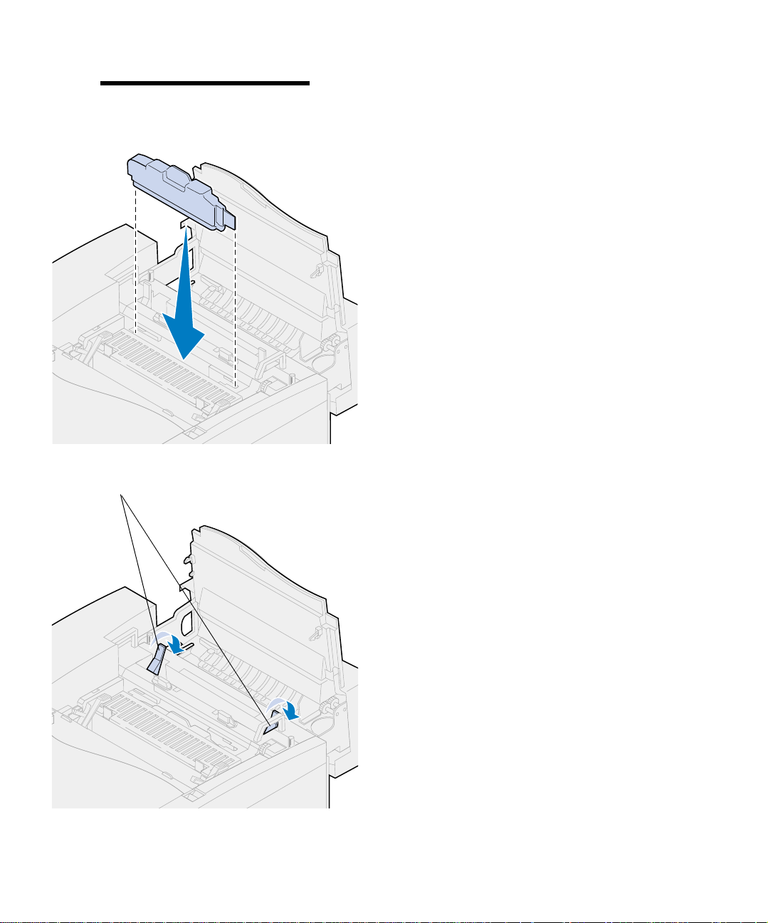
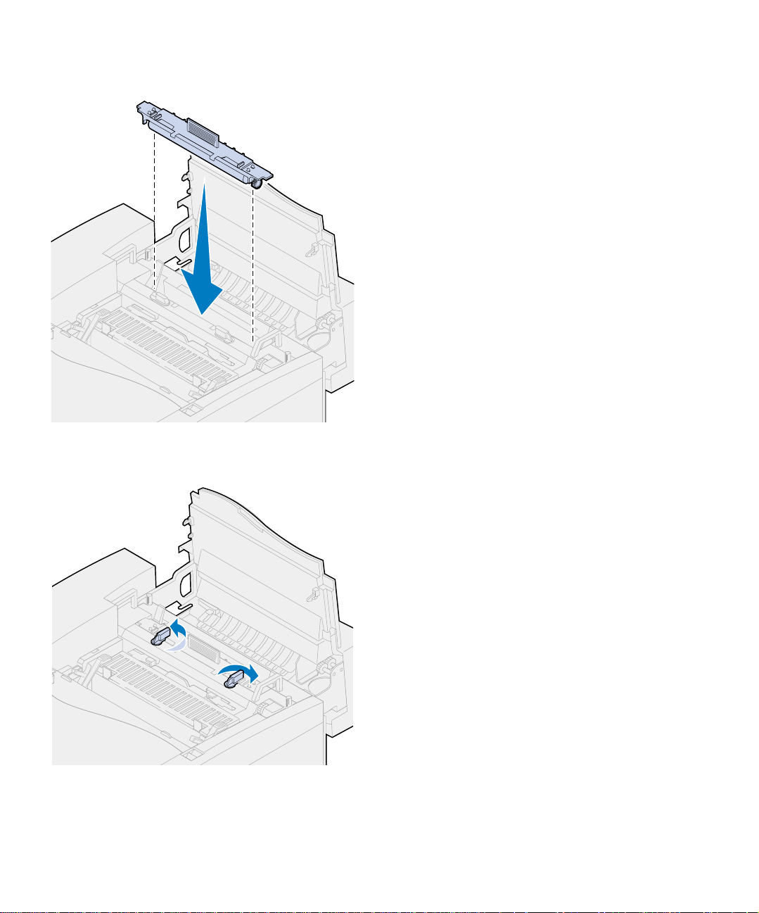
Top access panel
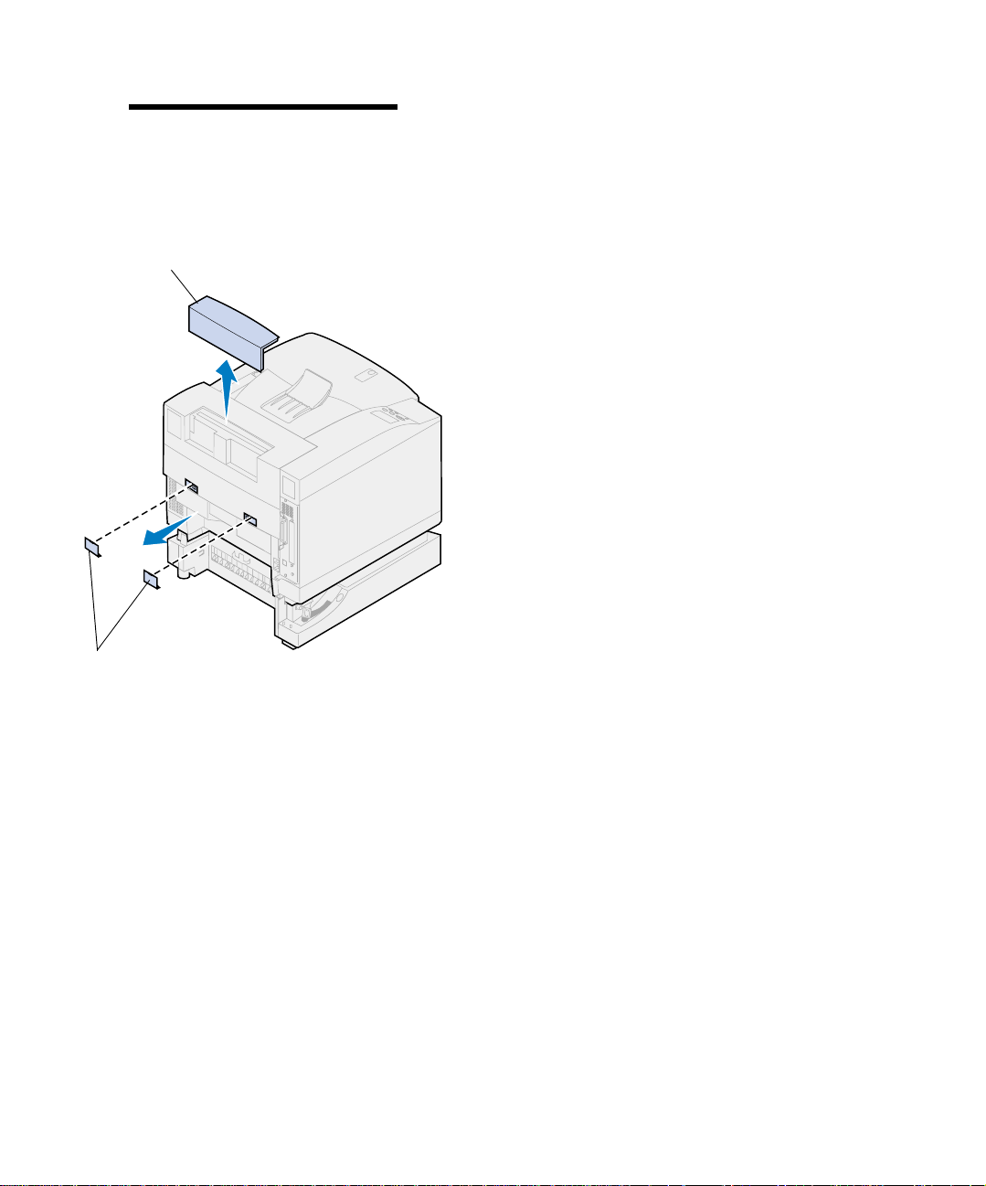
3 Remove the top access panel.
Push in on the bottom edge of the top access
panel. Then lift upward to remove it.
4 Pry outward on the rear tab covers an d
remove them.
You may need to use a small flathead screwdriver to remove the rear tab covers.
Tabs
Install the optional duplex unit
44
Page 49
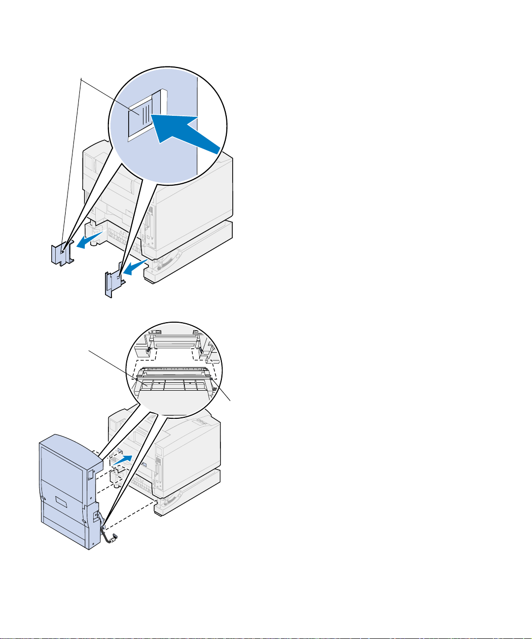
Lock
Pin
5 Press in on the left cover lock and slide the
cover off.
6 Press in on the right cover lock and slide
the cover off.
7 Insert the lower left and right pins on the
duplex unit into the slots of the op tional
drawer as shown.
Pin
8 Lift the duplex unit and place the tabs into
the holes of the printer.
9 Lower the du plex unit into place.
Install the optional duplex unit
45
Page 50

10 Open the duplex unit top cover.
11 Align the thumbscrews on the duplex unit
with the holes on the printer.
12 Tighte n the thumbscrews to secure the
duplex unit to the printer.
13 Close the duplex unit top cover.
14 Attach the black duplex unit connector to
the black printer connector.
Install the optional duplex unit
46
Page 51
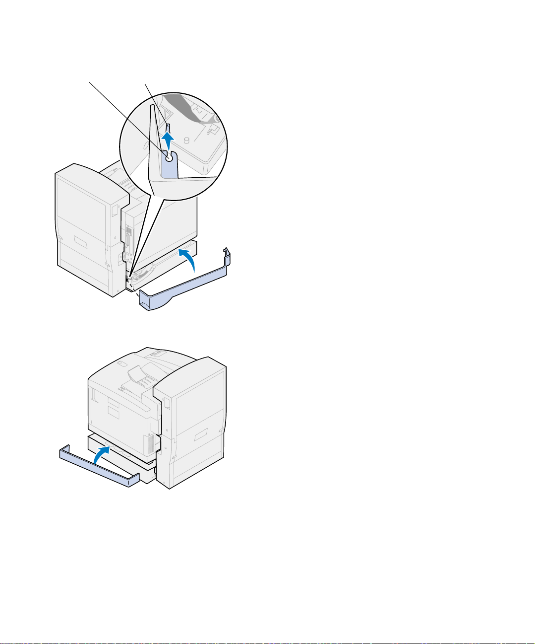
Slot
Pin
15 Install the left side access panel.
a Place the slot on the rear of the panel
onto the pin as shown.
b Rotate the panel toward the front of the
printer until it snaps into place.
16 Install the right side access panel.
a Place the rear of the panel into the rear
of the printer.
b Rotate the panel toward the front of the
printer until it snaps into place.
If you installed the duplex unit after initial
printer setup, connect the pri nter c ables and
power cord, and turn the printer on.
17 Continue with “Install supplies” on
page 49.
Install the optional duplex unit
47
Page 52

Install the optional duplex unit
48
Page 53

Step 7: Install supplies
Installing the oil bottle
and cleaning roll
Warning! It takes approximately 30
minutes for the oil to reach the fuser after
initial oil bottle installation. Make sure the
oil bottle has been installed for at least
30 minutes before printing.
Note: If a duplex unit is installed, open
the duplex unit top door also.
Your printer shi ps with an oil bottle and clea ning
roll that you must install to operate your printer.
Oil lubricates the fuser and the cleaning roll
removes excess toner and other contaminants
from the fuser.
Without oil, your fuser does not operate properly.
Insufficient lubrication cause s paper jams and
reduces the life of your fuser. You must wait 30
minutes after installing the oil bottle before printing.
To install the oil bottle and cleaning roll:
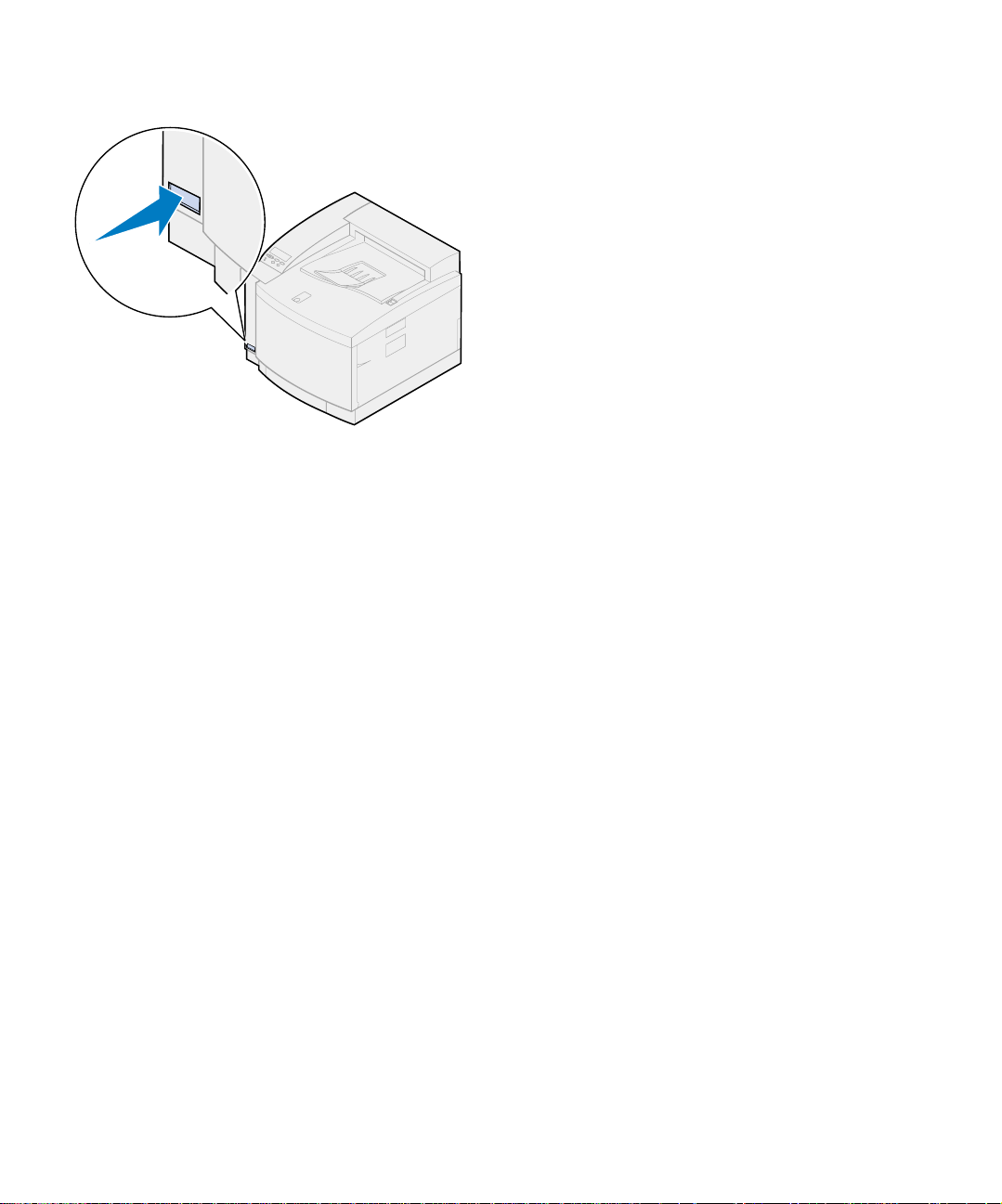
1 Slide the top door release latch toward the
front of the printer.
2 Lift the top do or.
Top door
release latch
Install supplies
49
Page 54
Warning! Once the oil bottle has been
installed, do not tilt or move the printer.
Oil can drip and cause damage. For
information on removing the oil bottle,
refer to the Lexmark C720 online information.
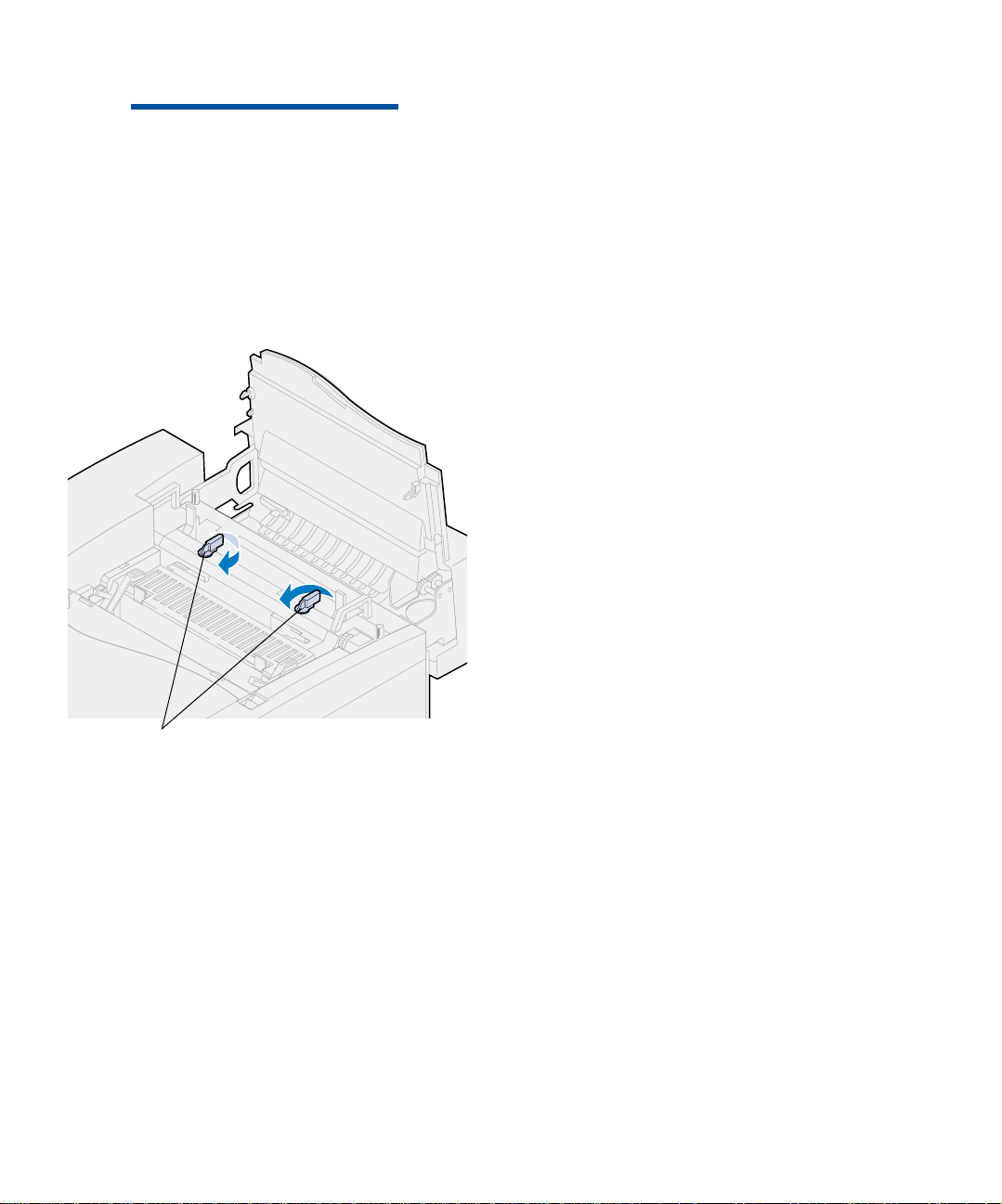
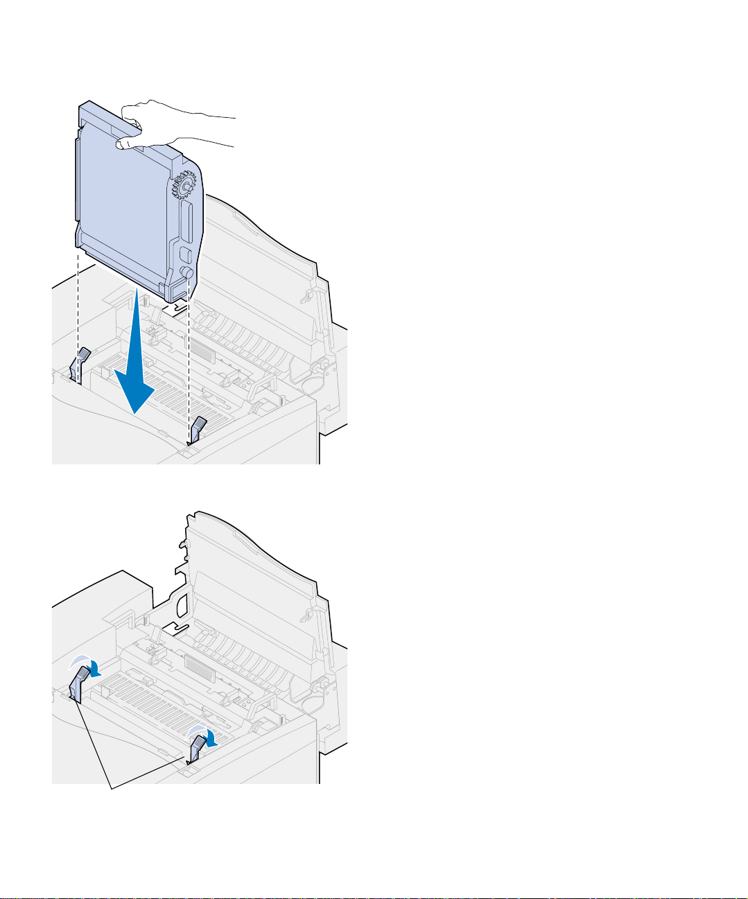
3 Turn the left and right green oil bottle
locking levers to unlock the oil bottle and
cleaning roll slots.
4 Remove the oil bottle from the packaging
material.
Oil bottle locking levers
Install supplies
50
Page 55
Important Oil may soil clothing.
5 Align the oil bottle with the slots in the
printer.
6 Lower the oil bottle into the printer.
Roller release levers
7 Move the green fuser roller release levers
toward the rear of the printer.
It may require some force to move the
levers.
Install supplies
51
Page 56
8 Remove the cleaning roll from the packing
material.
9 Remove any packing material or tape from
the cleaning roll.
10 Align the cleaning roll with the slot in the
printer.
11 Lower the cleaning roll into the printer.
12 Turn the left and right green oil bottle
locking levers to lock the oil bottle and
cleaning roll in the printer.
Install supplies
52
Page 57

Installing the photo
developer cartridge
Your printer ships with a photo developer cartridge that must be installed for your printer to
operate. The photo developer cartridge creates
and carries the image from the toner cartridges to
the transfer drum.
To install the photo develo per cartridg e:
1 Lift the left and right green photo devel-
oper locking levers.
Photo developer locking levers
Install supplies
53
Page 58
Warning! Do not touch the glossy
green film in the photo developer cartridge. T ouching the photo developer film
damages it and reduces print quality.
Metal shipping pin
Cover
Metal shipping pin
Photo developer film
2 Remove the photo developer cartridge
from the packing material.
3 Pull the two me tal shipping pins away
from the photo developer cartridge to
remove them.
The metal shipping pins have orange tape
on them.
4 Remove the cover, and any packing mate-
rial from the photo developer cartridge.
Do not leave the cartridge exposed to light
for more than 10 minutes. If the cartridge
will be exposed to light for longer than 10
minutes, place it in the box or cover it.
Make sure you do not scratch the surface of
the photo developer film. Scratches or tears
greatly affect print quality.
Install supplies
54
5 Discard the metal shipping pins and cover.
Page 59
6 Align the p hoto developer cartridge with
the slots in the green locking levers.
7 Lower the photo developer cartridge into
the printer until it is firmly seated.
Photo developer locking levers
8 Rotate the green ph oto developer locking
levers down.
Install supplies
55
Page 60

9 Close the top door.
If a duplex unit is instal led, cl ose the dupl ex
unit top door also.
Install supplies
56
Page 61

Installing the
toner cartridges
Your printer ships with four color-coded toner cartridges. These cartridges must b e placed inside the
front of the printer. Each cartridge has its own
color-coded position inside the printer.
To install the four toner cartridges:
1 Pull the front door release latch toward the
front of the printer.
2 Open the front door.
3 Remove an y shipping tape and packing
material from the front of the printer.
Check inside the toner ca rtridge compartment for packing material.
4 Remove a toner cartridge from the packing
material.
You can install the cartridges in any order.
However, it may be easier to install them in
the following order from bottom to top:
cyan, magenta, yellow, and black.
Front door release latch
5 Gently shake the toner cartridge to distrib-
ute the toner evenly.
Install supplies
57
Page 62
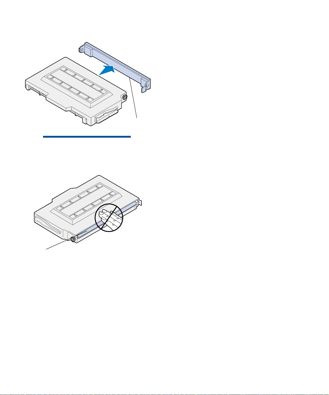
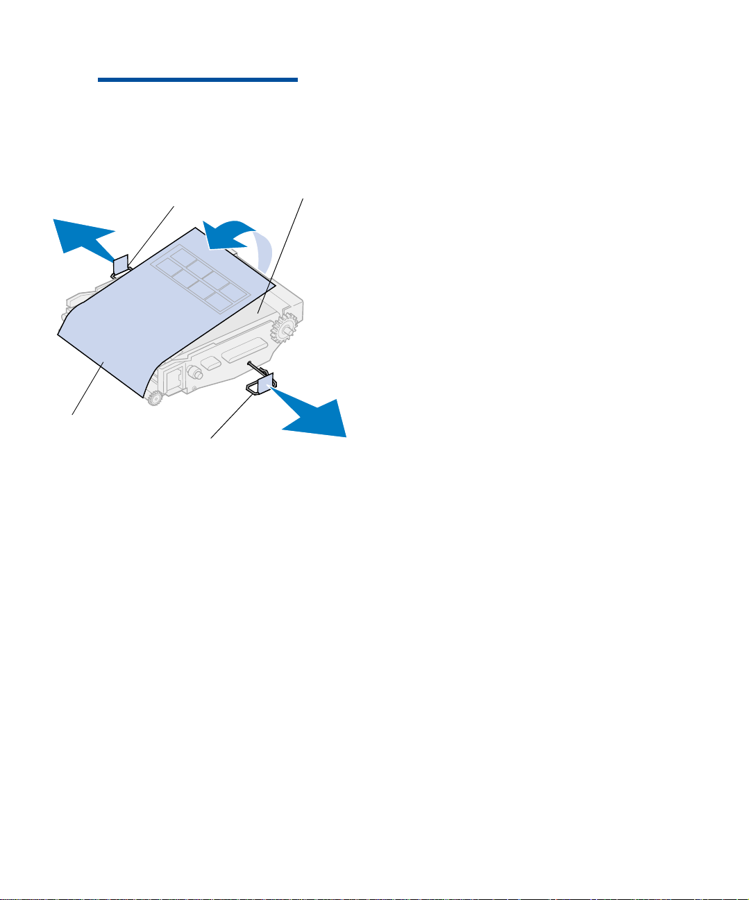
Cover
Warning! Do not touch the toner roller
surface under the cover. Touching the
surface of the toner roller may damage it.
6 Remove the cover and any other packing
material or tape from the toner cartridge.
Roller
Install supplies
58
Page 63
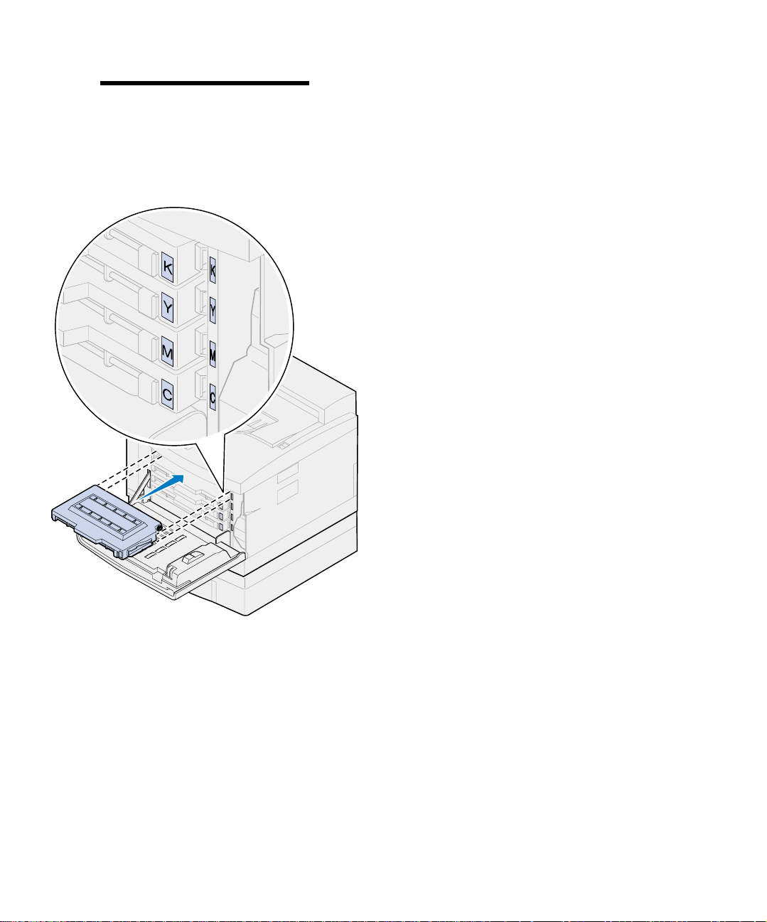
Note: Each cartridge is keyed to fit a
specific location inside the printer. If the
cartridge does not fit, make sure you are
placing the cartridge in the correct location.
7 Align the toner cartridge with the appro-
priate slot in the front of the printer.
The letter C, M, Y, or K on the toner cartridge corresponds with the letter inside the
printer.
8 Slide the new toner cartridge into the
printer.
Install supplies
59
Page 64
Attach the Quick
Reference Card
9 Repeat steps 4 throug h 8 to install the
remaining cartridges.
10 Close the front door.
Install supplies
60
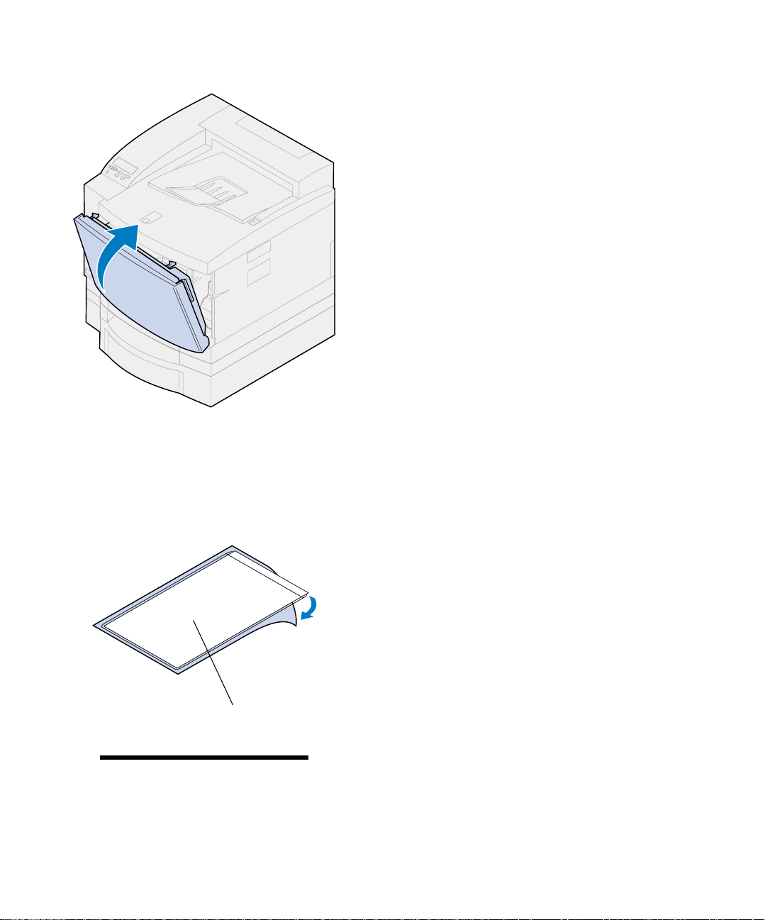
1 Find a convenient location for the Quick
Reference card.
2 Remove the protective pa per from the ba ck
of the Quick Reference sleeve.
3 Firmly press the adhesive-backed sleeve
onto the spot you have chosen.
Quick Reference sleeve
Note: Do not cover the vent holes on
the printer.
Page 65

Step 8: Attach the cab les
You can attach your printer to a LAN by:
• Connecting the printer dir ectly to the server
using a parallel, USB, or serial cable.
Your printer standard parallel port requires
an IEEE-1284 compliant parallel cab le. We
recommend Lexmark part number 1329605
(10 ft) or 1427498 (20 ft). If you use something other than an IEE E -compliant cable,
you may not be able to access all of your
printer functions.
If you’re attaching a serial cable, we recommend Lexmark part number 1038693 (50 ft).
Attach the cable to the serial connector on
the optional tri-port interface card you
installed in the printer.
CAUTION!When connecting a cable to
the printer from another powered component such as a computer or external
fax modem, make sure you turn off and
unplug the component power cord
before connecting any cables to the
printer.
• Connecting the printer directly to the LAN:
– Use an external print server such as Lex-
mark’s MarkNet Pro.
– Use a print server, such as the
MarkNet N2000 Series server described
on page 37.
– Use the optional tri-port interface card to
connect to a LocalTalk network.
For more information about your particular
interface card, refer to the documentati on
that came w ith it.
Attach the cables
61
Page 66
Note: Connect only one network cable
even if the internal print server has more
than one network port.
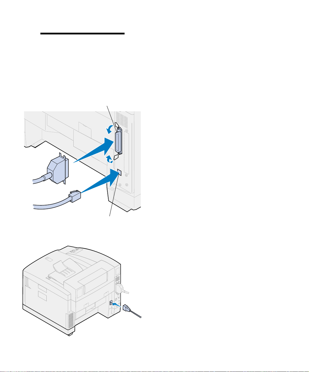
To attach a cable to your printer:
1 At the right rear of printer, locate the paral-
lel or the optional port connec tor.
Depending on the options you have
installed, additional parallel, serial, USB, or
network connectors may be available.
Parallel connector
Optional Ethernet
connector
2 Connect the appropriate cable.
3 Plug the power cord into rear of the printer
and into a properly grounded electrical
outlet.
Attach the cables
62
Page 67
4 Turn the pri nte r on.
5 Continue with “Load the paper tray” on
page 65.
Attach the cables
63
Page 68

Attach the cables
64
Page 69
Step 9: Load the paper tray
Your printer has one standard 250-sheet tray—
tray 1—that holds A4, letter, and executive size
paper. An optional 250-sheet legal tray is also
available. You can also load transparencies, envelopes, and card stock in tray 1. F or details about
the types of media your printer supports, refer to
the Lexmark C720 online information.
Note: If you load transparencies in
tray 1, make sure you change the Paper
Type setting to Transparency. See
“Changing the Paper Type setting” on
page 77 for more information.
If you installed an optional paper drawer, the
instructions are the same for loading paper in that
tray. However, load only paper in tray 2.
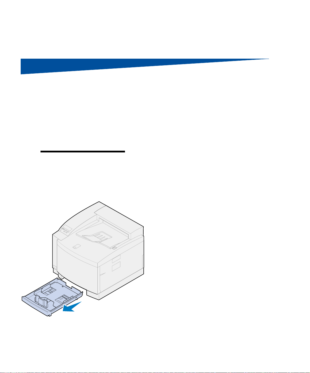
To load the tray:
1 Pull the paper tray completely out of the
printer.
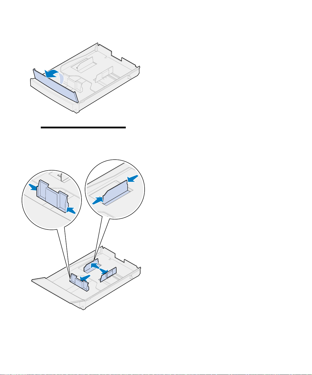
2 Set the paper tray on a flat surface.
Load the paper tray
65
Page 70
Note: If you are loading A4 or letter
size paper, the tray may already be set
up for the appropriate paper size.
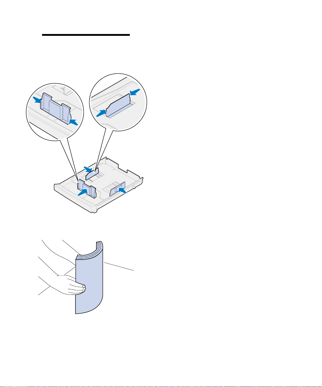
3 Squeeze the snap locks on the end of the
front paper guide.
4 Slide the front paper guide to align with
the position of the paper size you are loading.
5 Release the snap locks.
The position of the front paper guide tells
the printer the size of the paper in the tray. If
the front paper guide is in the wrong position, you may experience paper feeding
problems or incorrect page format ting.
6 Squeeze the snap locks on the end of the
left side paper guide.
7 Slide the left side paper guide to align
with the position of the paper size you are
loading.
Load the paper tray
66
8 Release the snap locks.
9 Before loading the paper, flex the sheets
back and forth to loosen them, and then
fan them. Straighten the edges on a level
surface.
Page 71
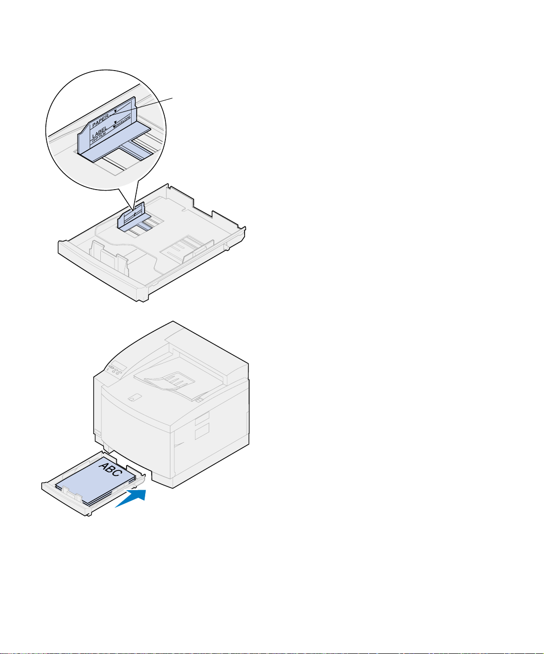
10 Load the paper with the recomm ended
print side face up.
Maximum
stack height
Do not exceed the maximum stack height
indicated on the label inside the paper tray.
If you’re loading preprinted letterhead,
place the top of the page at the rear of the
tray.
11 Slide the paper tray into the printer.
Load the paper tray
67
Page 72

Loading envelopes
Load envelopes only in tray 1. To load the tray:
1 Pull the paper tray completely out of the
printer.
2 Set the paper tray on a flat surface.
3 Squeeze the snap locks on the end of the
front paper guide.
4 Slide the front paper guide to align with
the position of the envelope size you are
loading.
Snap locks
Load the paper tray
68
5 Release the snap locks.
The position of the front paper guide tells
the printer the size of the envelope in the
tray.
For some envelopes, you may have to set
the envelope size through the operator
panel.
If the front p ape r guide is in the wro ng position, you may experience envelope feeding
problems or incorrect formatting.
6 Squeeze the snap locks on the end of the
left side paper guide.
Page 73

Maximum
stack height
7 Slide the left side paper guide to align
with the position of the en velope size you
are loading.
8 Release the snap locks.
9 Before loading the envelopes, flex them
back and forth to loosen them, and then
fan them. Straighten the edges on a level
surface.
10 Load the envelopes with the recommended
print side face up and the return address
area toward the front of the printer.
Do not load stamp ed envelopes.
Do not exceed the maximum stack height
indicated on the label inside the paper tray.
Load the paper tray
69
Page 74

11 Slide the paper tray into the printer.
Loading the optional
legal paper tray
The optional legal paper tray replaces tray 1, the
standard 250-sheet tray. In addition to legal size
paper, you can load all the paper sizes and types
supported by the standard tray 1.
To load the tray:
1 Place the legal paper tray on a flat surface.
Load the paper tray
70
Page 75
Note: The paper tray may already be
set up for the appropriate paper size.
2 Lift the front tray cover.
3 Squeeze the snap locks on the end of the
front paper guide.
4 Slide the front paper guide to align with
the position of the paper size you are loading.
5 Release the snap locks.
The position of the front paper guide tells
the printer the size of the paper in the tray. If
the front paper guide is in the wrong position, you may experience paper feeding
problems or incorrect page format ting.
6 Squeeze the snap locks on the end of the
left side paper guide.
7 Slide the left side paper guide to align
with the position of the paper size you are
loading.
8 Release the snap locks.
Load the paper tray
71
Page 76

9 Before loading the paper, flex the sheets
back and forth to loosen them, and then
fan them. Straighten the edges on a level
surface.
10 Load the paper with the recomm ended
print side face up.
Maximum
stack height
Do not exceed the maximum stack height
indicated on the label inside the paper tray.
If you’re loading preprinted letterhead,
place the top of the page at the rear of the
tray.
11 Lower the front tray cover.
Load the paper tray
72
Page 77

12 Slide the paper tray into the printer.
Load the paper tray
73
Page 78

Load the paper tray
74
Page 79

Step 10: Verify setup
Print a menu settings page to review default
printer settings and identify all of your installed
options. The menu settings page also indicates
whether options are operating correctly.
1 Turn the printer on.
After you turn the printer on, it performs a
self test and warms up. During this period,
the messages
ing
Engine appear on the operator panel dis-
play.
The self test and warm-up period ensure all
components function and the printer is at
the correct operating temperature.
If you see an error code on the operator
panel display, refer to the Troubleshooting
section in the Lexmark C720 online information.
Performing Self Test and Warm-
After the printer completes its internal tests
and warms up, the
appears.
For more information about using the
printer operator panel, changing display
languages, and changing menu settings,
refer to the Lexmark C720 online information.
Ready status message
Verify setup
75
Page 80
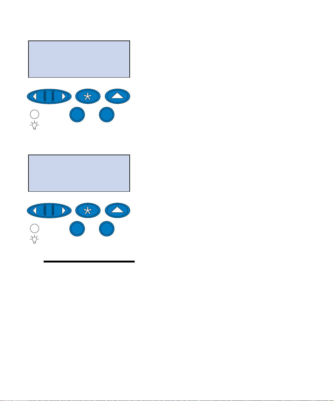
Ready
1
Menu
2
Go
Select
5
UTILITIES MENU
3
Return
Stop
Power Saver is set at 20 minute s (the fact ory
default). You can set the Power Saver time
to a value between 0 and 240 minutes.
Power Saver replaces the Ready status mes-
sage after the specified period of time. Both
messages indicate the printer is ready to
4
receive print jobs . Refer to the Lexm ark
C720 online information for more information about modifying the Power Saver setting.
2 From the printer operator panel, pre ss
6
Menu> or <Menu to enter the operator panel
menus.
3 Continue to pre ss and release Menu> or
<Menu until UTILITIES MENU appears on the
operator panel.
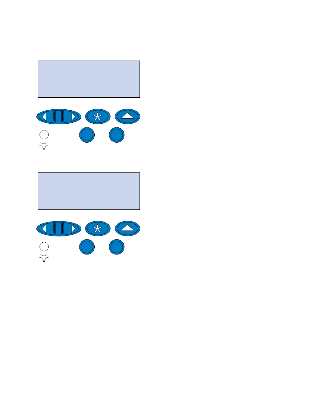
Print Menus
1
Menu
2
Go
Note: Before printing the menu set-
tings page, make sure the selected
paper source holds A4 or letter size
paper. If you use a paper type other than
plain paper, you need to set the printer to
the correct type. Refer to the Lexmark
C720 online information for more information on paper sizes and sources.
Select
5
3
Return
Stop
6
4 Press Select.
4
UTILITIES MENU appears on the first line,
Print Menus is on the second line.
and
5 Press Select again to print the menu set-
tings page.
The message
The printer returns to
menu settings page prints.
If an error message appears on the display,
refer to the Troubleshooting section on the
Lexmark C720 online information for more
information.
Printing Menu Settings appears.
Ready status after the
76
Verify setup
Page 81

6 Ve rify the options you installed are listed
on the menu settings page under
“Installed Features.”
If an option you installed does not appear
on the page, turn the printer off, unplug the
power cord, and reinsta ll th e option.
7 If you attached a serial cable, verify the
printer serial settings listed on the menu
settings page are appropriate for your system.
For more informat ion abou t the Seri al Menu
and changing these settings, refer to the
Lexmark C720 online information.
Changing the
Paper Type setting
It is important to verify the Paper Type settings are
accurate for all the installed paper sources. Refer
to the menu settings page you printed. The Paper
Type is listed for each of the instal led paper
sources.
Paper Type refers to the type of media loaded in
the sources: plain paper, letterhead, envelopes,
and transparencies. Since tray 1 can hold different
media, you can customize tray 1 Paper Type settings.
The printer uses the Paper Type setting to optimize print quality for the media you specified. For
example, selecting the Transparency paper type
slows the printing process to produce the best
transparency possible.
The Paper Type setting also affects the printer
automatic source selection ca pability, as well as
the tray linking function. For these reasons, it’s
important to change the setting each time you
change the media in the trays.
Refer to the Lexmark C720 online information for
more detailed information about the paper types
supported by each paper source, as well as ways
Verify setup
77
Page 82
to use the Paper Type setting to make printing
more efficient.
If you need to change a Paper Type setting:
1 From the printe r operator panel, press
Menu> or <Menu to enter the menus.
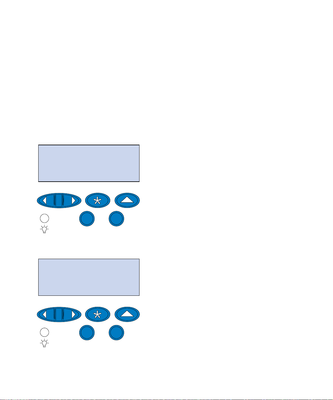
PAPER MENU
1
Menu
2
Go
Select
5
PAPER MENU
PAPER TYPE
1
Menu
2
Go
Select
5
3
3
Stop
Stop
Return
6
Return
6
PAPER MENU appears on the second line of
4
the display.
2 Press Select to open the Paper Menu.
3 Press and release Menu> until PAPER TYPE
appears on the second line.
4
78
Verify setup
Page 83

4 Press Select.
PAPER TYPE
Tray 1 Type
1
Menu
2
Select
Go
Tray 1 Type
=Plain Paper*
1
Menu
2
Select
Tray 1 Type appears on the second line of the
display.
5 Press Select again if you want to change the
Return
6
4
3
5
Stop
Tray 1 T ype setting or press
to change to Tray 2 Type and then press
Select.
Menu> or <Menu
6 Press Menu> or <Menu to scroll through a
list of possible paper types for tray 1.
7 When the correct paper type appears on
the second line of the display, press
again to save the type as the default for
Return
4
3
tray 1.
Select
8 When you are finished changing the Paper
T ype settings, press
to the ready state.
Go to return the printer
Go
5
Stop
6
9 If you have an optional tray or duplex u nit
go to “Adju sting tray 2 and duplex unit
margins” on page 80, otherwise continue
with “Load MarkVision and drivers” on
page 89.
Verify setup
79
Page 84
Adjusting tray 2 and
duplex unit margins
Adjusting the tray 2 and duplex unit margins
makes sure your margins ar e consistent when t ray
linking is enable d and when duplex printing is
selected. The left margin of your optional tray or
duplex unit may not match the printed left margin
of tray 1. If you have an optional drawer or duplex
unit, use the following procedures to verify and
adjust your left margins:
Determining the correct
SETUP MENU
1
Menu
2
Go
Select
5
SETUP MENU
LEFT MARGIN
tray2margin
Return
6
4
3
Stop
1 Make sure you have plain paper loaded in
tray 1 and tray 2.
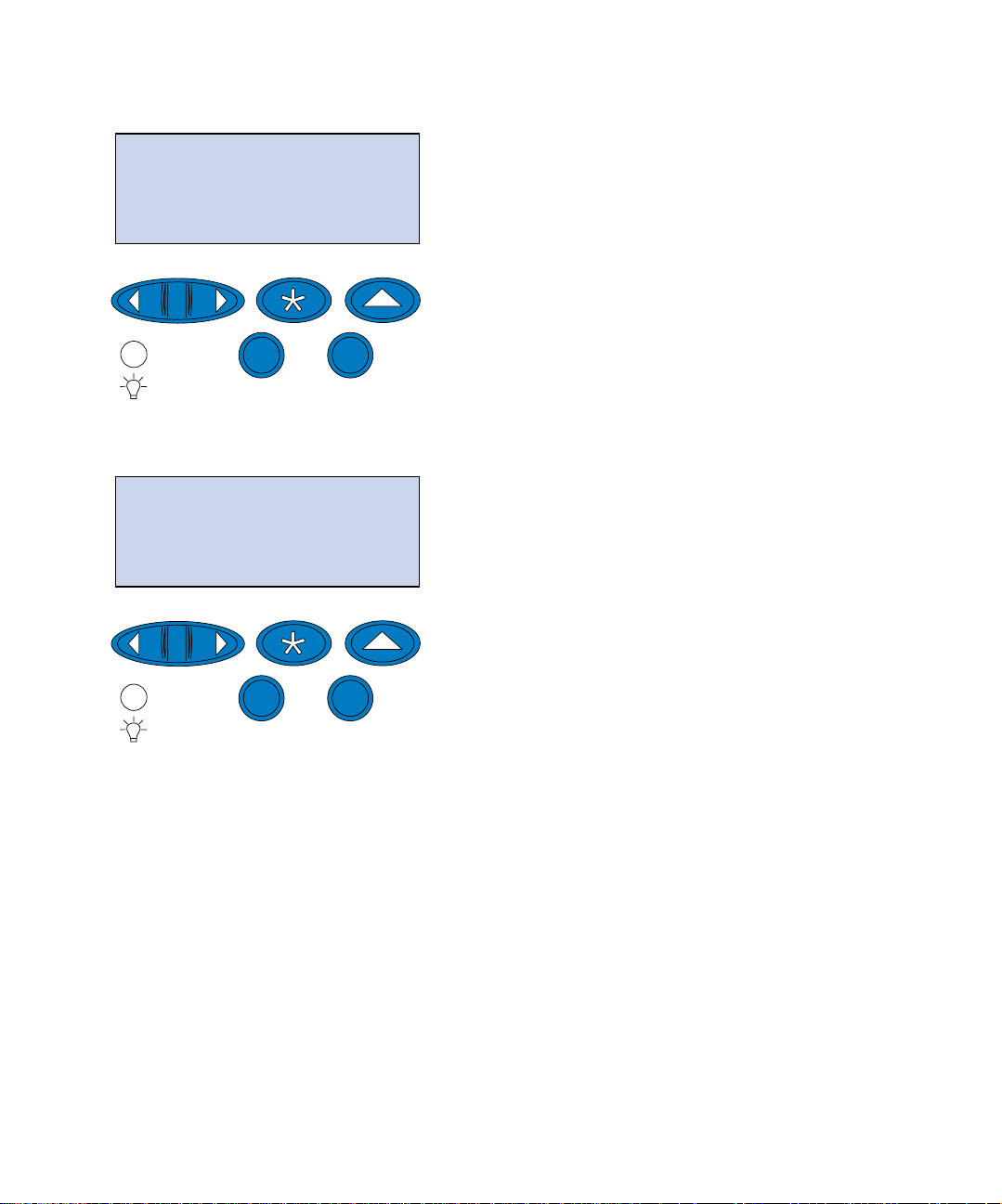
2 From the printer operator panel, pre ss
Menu> or <Menu until SETUP MENU appears
on the second line of the display.
3 Press Select to open the Setup Menu.
4 Press Menu> or <Menu until LEFT MARGIN
appears on the second line of the display.
5 Press Select to open the Left Margin menu.
80
1
Verify setup
Menu
2
Go
Select
5
3
Stop
Return
6
4
Page 85
LEFT MARGIN
Tray 2
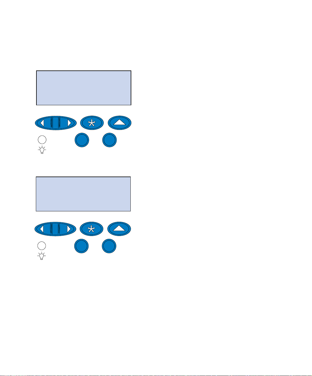
6 Press Menu> or <Menu until Tray 2 appears
on the second line of the display.
1
Menu
Tray 2
= 5*
1
Menu
2
Go
Select
5
3
Stop
Return
6
4
7 Press Select to open the Left Margin value.
Tray 2 appears on the first line and the cur-
rent default value appears on the second
line of the display .
2
Go
Select
5
3
Stop
Return
6
4
8 Press Select to print the two alignment
pages.
Printing Alignment Page appears on the dis-
play.
One page prints from tray 1 and the other
from tray 2.
The numerical value with (*) printed on the
tray 2 page is the current default value.
Verify setup
81
Page 86
Adjusting the
tray 2 margin
Note: After the margin adjust ment
pages are printed, the printer returns to
Ready.
Instructions
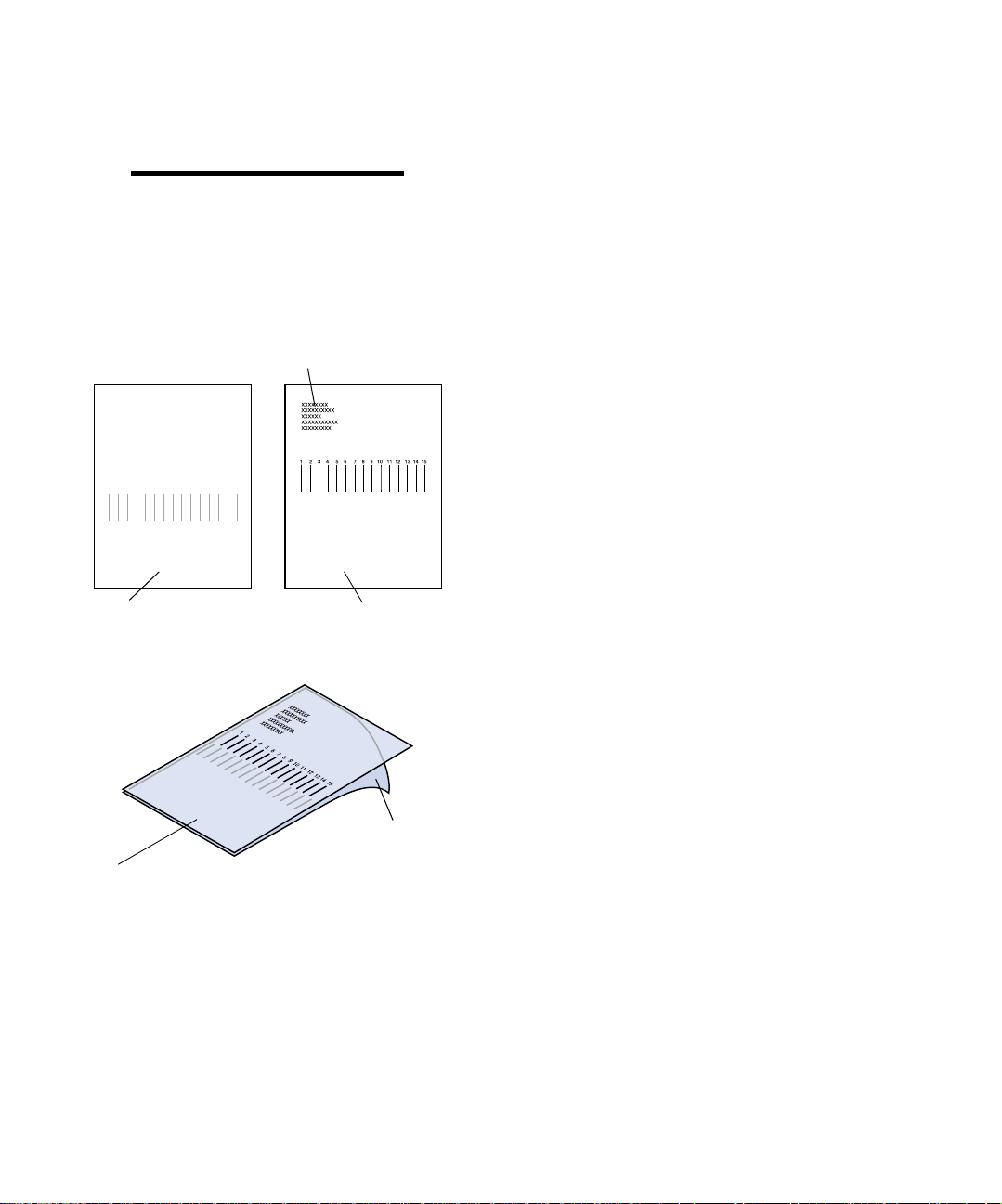
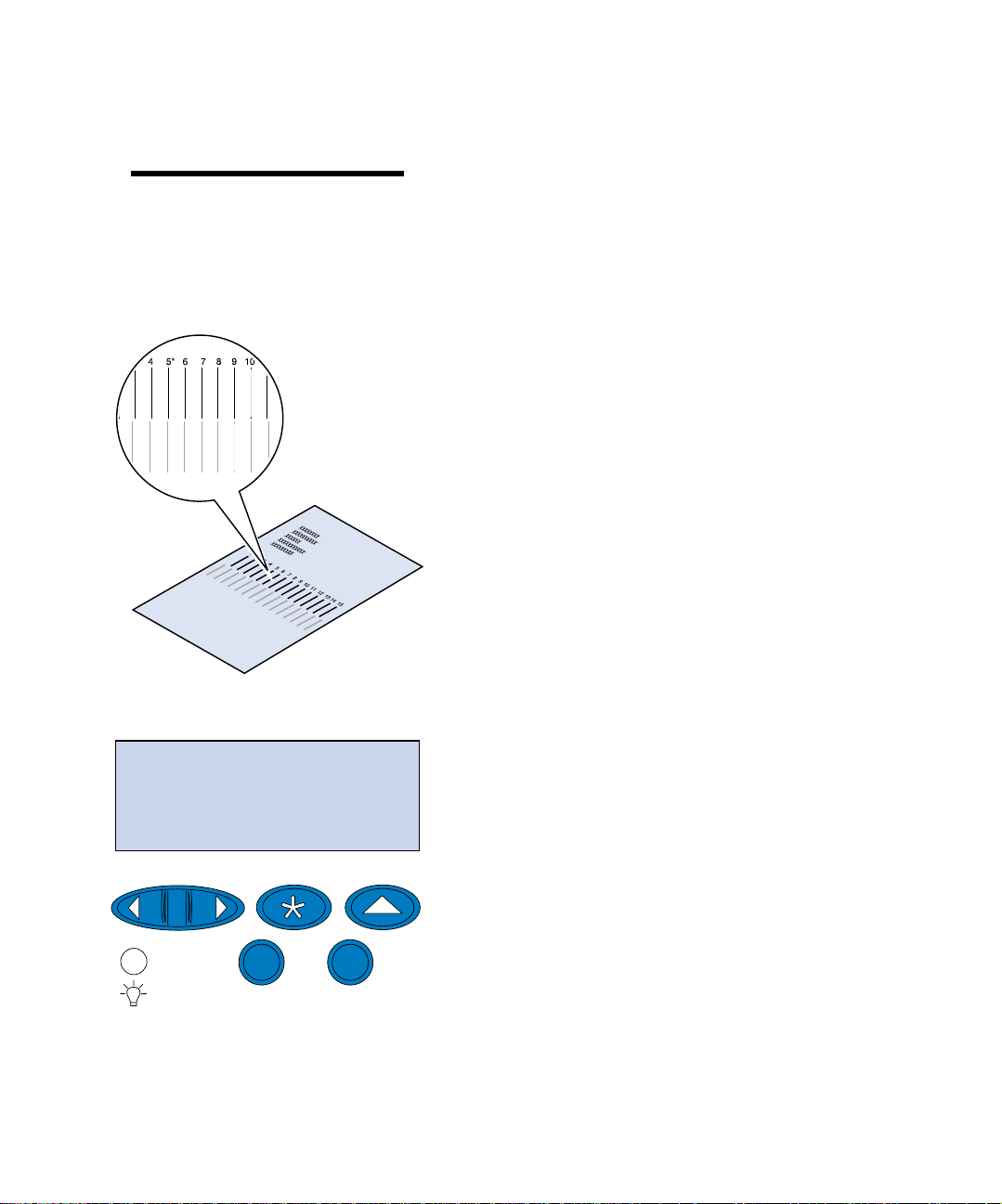
Tray 1 page Tray 2 page
Each page has 15 vertical lines printed across the
page.
The tray 2 page has adjustment instructions in the
upper left c orner and a numerical value above
each vertical line.
1 Place the page from tray 2 on top of the
page from tray 1.
Tray 2 page
82
Tray 1 page
Verify setup
Page 87
Tray 2
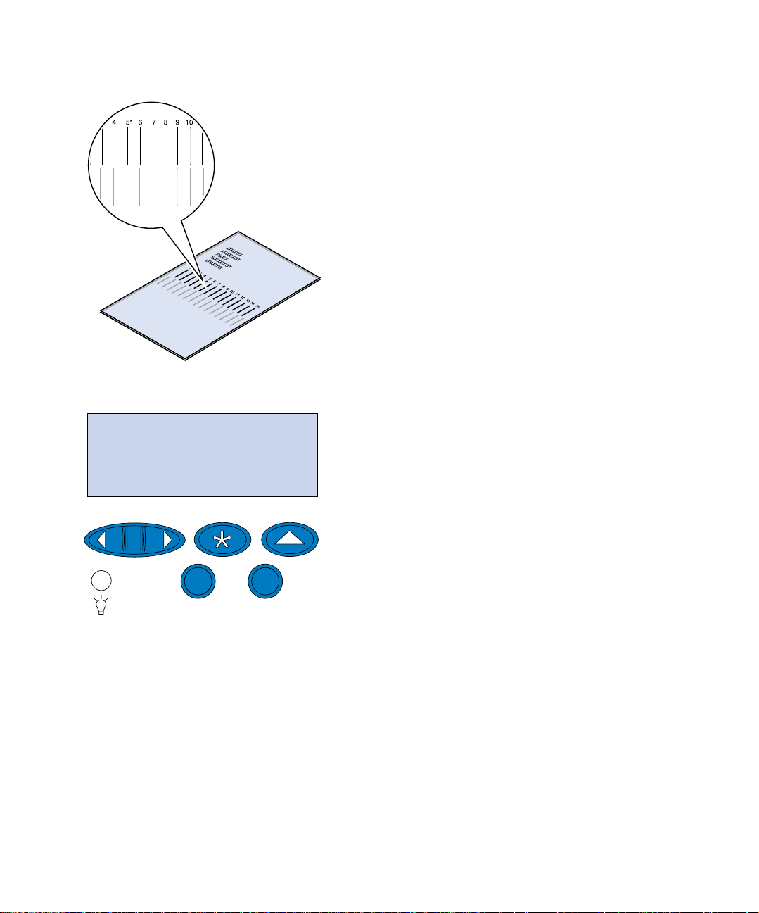
2 Hold the pages up toward the light and
find the lines that most closely form a single vertical line.
3 The numerical value abo ve the lines that
most closely forms a vertical line is your
new setting.
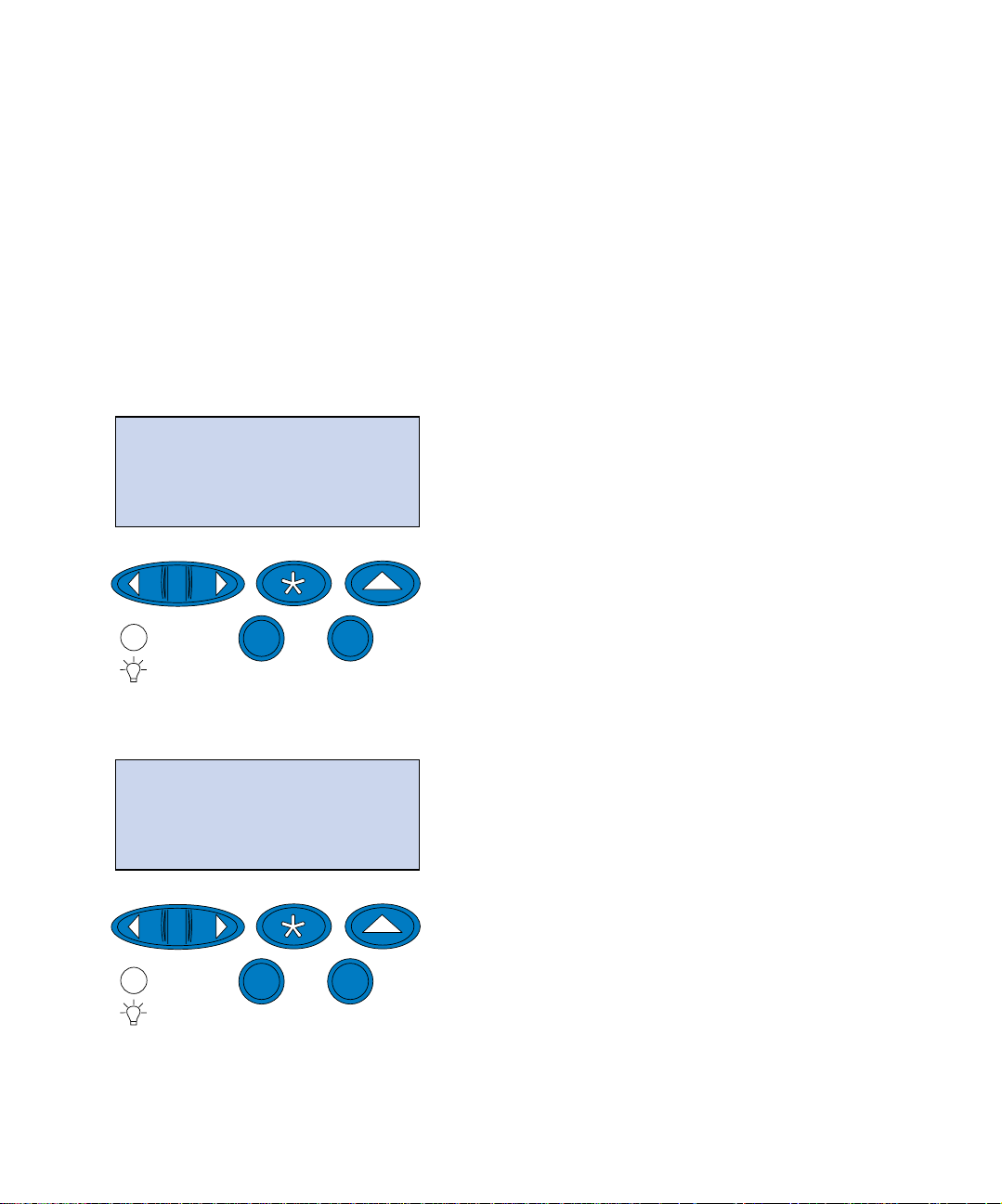
4 Repeat steps 1 through 7 on pages 80
through 81, then continue with step 5 on
page 83.
= 8*
1
Menu
5 Press <Menu or Menu> until you see the
numerical value you want to select.
2
Go
Select
5
3
Stop
Return
6
4
Verify setup
83
Page 88

Tray 1 page Tray 2 page
Tray 2 page
6 Press Select to save the new alignment set-
ting and print the two alignment pages.
7 Place the page from tray 2 on top of the
page from tray 1.
Tray 1 page
84
8 Hold the pages up toward the light and
find the lines that most closely form a single vertical line.
If the numerical value above the matching
vertical lines has an * alongside it, the margins are aligned properly.
If the lines that most closely form a single
line do not have the numerical value and
an *, your margin is not adjusted properly.
Verify setup
Page 89
9 Repeat steps 1 through 8 if further adjust-
ment is required.
10 If you have an optional duplex unit, see
“Determining the correct duplex unit margin”. Otherwise continue with “Load
MarkVision and drivers” on page 89.
Determining the correct
duplex unit margin
SETUP MENU
1
Menu
2
Go
Select
5
SETUP MENU
LEFT MARGIN
3
Stop
Return
6
1 Make sure you have plain paper loaded in
tray 1.
2 From the printer operator panel, pre ss
Menu> or <Menu until SETUP MENU appears
on the second line of the display.
3 Press Select to open the Setup Menu.
4
4 Press Menu> or <Menu until LEFT MARGIN
appears on the second line of the display.
5 Press Select to open the Left Margin menu.
1
Menu
2
Go
Select
5
3
Stop
Return
6
4
Verify setup
85
Page 90

LEFT MARGIN
Duplex
6 Press Menu> or <Menu until Duplex appears
on the second line of the display.
1
Menu
Duplex
= 5*
1
Menu
2
Go
Select
5
3
Stop
Return
6
4
7 Press Select to open the Left Margin value.
Duplex appears on the first line and the cur-
rent default value appears on the second
line of the display .
2
Go
Select
5
3
Stop
Return
6
4
86
8 Press Select to print a duplex alignment
page.
Printing Alignment Page appears on the dis-
play.
Verify setup
Page 91
Adjusting the
duplex unit margin
Note: After the margin adjust ment
pages are printed, the printer returns to
Ready.
Duplex
= 8*
Each page has 15 vertical lines printed across the
page.
The back page has adjustment instructions in the
upper left c orner.
1 Hold the page up toward the light and find
the lines that most closely form a single
vertical line.
The numerical value above the lines that
most closely forms a vertical line will be
your new setting.
2 Repeat steps 1 through 7 on pages 85
through 86, then continue with step 3 on
page 87.
3 Press <Menu or Menu> until you see the
numerical value you want to select.
4 Press Select to save the new alignment set-
ting and print the alignm ent page.
1
Menu
2
Go
Select
5
3
Stop
Return
6
4
Verify setup
87
Page 92

5 Hold the pages up toward the light and
find the lines that most closely form a single vertical line.
If the numerical value above the matching
vertical lines has an * alongside it, the margins are aligned properly.
If the lines that most closely form a single
line do not have the numerical value and
an *, your margin is not adjusted properly.
6 Repeat steps 1 through 5 if further adjust-
ment is required.
88
Verify setup
Page 93

Step 11: Load MarkVision and
drivers
The compact disc (CD) shipped with your printer
contains the printer drivers and utilities for Windows 95/98/Me, Windows NT 4.0, Windows
2000, and Macintosh. Drivers are available for
both PostScript 3 and PCL emulations.
Refer to the CD Readme file for a co mplete list of
all the drivers included on the CD. Updated drivers, as well as a complete description of the driver
packages and Lexmark driver support, are also
available electronic ally fro m the Lexmark W e b site
on the World Wide Web at www.lexmark.com.
To su pport all the printer’s features, install the
custom Lexmark drivers on your system. If you
use drivers designed for printers other than the
Lexmark C720, you may not be able to control all
of the printer’s functions . Fo r mo re information
about these functions, refer to th e driver online
Help.
In addition to printer drivers, you may be interested in insta lling the MarkVision
MarkVision provides numerous printer management tools that can help you set up a network of
printers, mo nitor the status of the printers, and
collect information about printer use. For more
information about MarkVision features and installation, refer to the MarkVision information on the
Drivers, MarkVision and Utilities CD, or access the
Lexmark C720 online information.
printer ut ility.
1 Launch the Drivers, MarkVision and Utili-
ties CD.
Load MarkVision and drivers
89
Page 94

Refer to the boo klet included with the CD
for information about la unching the CD for
your operating system.
When you launch the CD, the CD program
displays icons or text items that let you
choose what you want to do.
If necessary, you can change the language of
the text the CD displays on the screen. This
also changes the language of the text displayed on the user interface screens for the
drivers and utilities you choose to install.
Note: To use your printer most effec-
tively, we recommend you install the custom Lexmark printer drivers appropriate
for your printing environment.
Congratulations! You have successfully set up your Lexmark C720.
2 Select the appropriate icon to:
– Install printer drivers.
– Install the MarkVision printer utility.
– Install network support.
– Install screen fonts.
– View the CD Readme file.
– Access Lexmark support phone num-
bers.
– Register your printer (Windows operat-
ing systems only).
At any time the CD program is running, press F1
for online Help. Refer to the CD Readme file for
the latest i nformation about the contents of the
CD.
If you need to configure your printer for use on a
network, continue with Step 12: “Configure the
network printer” on page 91.
Refer to the Lexmark C720 online information for
complete information about all of the unique features of your Lexmark color printer.
Load MarkVision and drivers
90
Page 95

Step 12: Configure the network
printer
Printing a network
setup page
Note: The UAA is preset at the factory.
However, you can override it with an
optional locally administered address
(LAA) if you want a particular physical
address for this print server.
Use the printer operator panel to print the network setup page. You will need this information
during network setup.
The network setup page shows the physical
address, known as the universally administered
address (UAA), of the print server and other
important data. Look for the UAA under the Network heading on the setup page.
The UAA is a 12-digit number. The left column
shows the address in MSB form and the right column shows the address in canonical form.
Configure the network printer
91
Page 96
NETWORK MENU
NETWORK OPTION 1
1
Menu
2
Select
3
Return
To print the network setup page:
1 From the operator panel, press Menu> or
<Menu to enter the menus.
2 Continue to pre ss and release Menu> or
<Menu until you see NETWORK MENU.
3 Press Select.
NETWORK OPTION 1 appears on the second
4
line of the display. If necessary, press
<Menu to display the correct network
or
Menu>
option.
4 Press Select.
Go
5
Stop
NETWORK OPTION 1
NETWORK 1 SETUP
1
Menu
2
Go
Select
5
3
Return
Stop
6
5 Press Menu> or <Menu until you see NET-
WORK 1 SETUP
display.
4
6
on the second line of the
Configure the network printer
92
Page 97

6 Press Select.
NETWORK 1 SETUP
Print
1
Menu
2
Go
Select
5
3
Return
Stop
Print
Print Setup Pa ge
1
Menu
2
Select
3
Return
7 Press Menu> or <Menu until you see Print on
the second line of the display.
4
6
8 Press Select.
Print Setup Page appears on the second line
of the display.
9 Press Select to print the page.
4
Go
Stop
6
Configure the network printer
93
5
Page 98
Configuring and
printing
If you have more than one version of the Drivers,
MarkVision and Utilities CD, always use the latest
version.
For troubleshooting information, look on the Driv-
ers, MarkVision and Utilities CD. Click View Docu-
mentation and look for the MarkNet link.
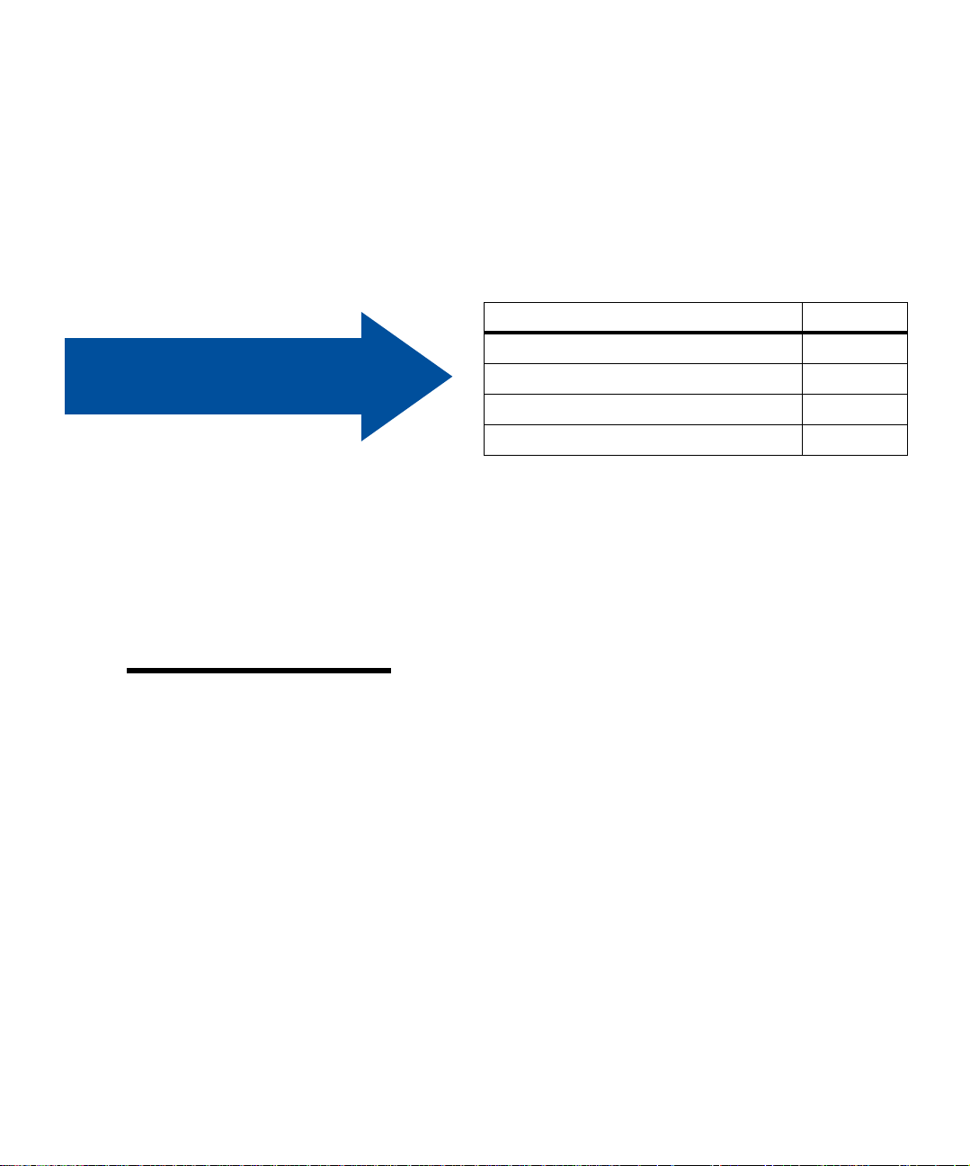
If your network environment is… See page…
Use the table to the right
to locate your next step.
Set the IP address,
netmask, and gateway
Note: For instructions on other ways to
set the IP address, look on the Drivers,
MarkVision and Utilities CD. Click View
Documentation and look for the MarkNet link.
TCP/IP 94
Novell NetWare 100
AppleTalk 101
OS/2 Warp Server 103
TCP/IP
You must assign an IP address, netmask, and gateway to the print server for other network devices
to find the printer on the ne twork.
• If you have DHCP, the proper address values are automatically assigned. To verify the
assignment has occurred, print a network
setup page and make sure the IP address,
netmask, and gatewa y appear as non-zero.
Configure the network printer
94
• If you don’t have DHCP, there are other
methods you can use to manual ly assign the
address such as the printer operator panel,
static ARP and telnet, RARP and telnet,
BOOTP, MarkVision, or other Lexmark utility. Inst ructions for these methods follow.
Page 99

Printer operator panel
A simple way to set the IP address, netmask, and
gateway inside the print serve r is to use the operator panel. You need to be standing at the printer to
use this method.
Note: “X” designates option slot in the
printer being used. For example, if you
install the MarkNet card in option slot 2,
the operator panel selection shows:
work Option 2
.
Net-
1 From the operator panel, choose Network
Menu, Network Option X, Network Option X
, TCP/IP, Set IP Address. (Hint: Press
Setup
Menu> until you see the correct menu item,
and then press
Select.)
2 When the current IP address appears, use
the menu buttons to change the address.
(Hint: Press
segment in the address. Press
increase the number by one.
decrease the number by one.)
Select to advance to the next
Menu> to
<Menu to
3 Press Select until the word SAVED appears
briefly.
4 Repeat steps 1 through 3 to Set IP N etmask
and then again to Set IP Gateway.
5 Print a new netw ork setup page to verify
the parameters are set as you intended.
Static ARP and telnet
Note: The computer and the printer
must be on the same subnet.
You can use this method from any Windows,
OS/2, or UNIX computer. You need to know the
physical address of the print server to use this
method.
1 Find the physical address (UAA) of the
print server (for example, 0020 0022012F) on
the network setup page you printed earlier.
If you have an Ethernet network, use the
number in the right column (canonical). If
Configure the network printer
95
Page 100

you have a Token-Ring network, use the
number in the left column (MSB).
2 Set the IP ad dress in your computer A R P
table.
At a DOS prompt, type a command line containing the IP address you want to assign
and the UAA. The following is an example
of an IP address and UAA command line.
arp -s 192.168.236.24 00-20-00-22-01-2F
3 Set the IP address, netmask, and gateway
in the print server.
Telnet to port 9000 on the print server by
typing a command similar to the following:
telnet 192.168.236.24 9000
4 Ve rify the print server is up and ru nning
on the network.
ping 192.168.236.24
Note: If you are using Windows 2000
or Windows NT Server 4.0 or later and
running TCP/IP, you can use Network
Plug and Print to automate your printer
setup process.
Configure the network printer
96
Set up to print There ar e many ways to send a pri nt job incl uding
FTP, TFTP, LPR/LPD, point-to-point (LexIP), and
various queue-based methods. Instructions for
two of the methods follow.
Print to a queue on a Windows NT server
This section explains the setup for queue-based
printing where network users print to a queue
defined on a Windows NT server. The print server
services this queue.
To use this method, you must have at least one
server running Windows NT Server software and
TCP/IP.
The following in structions apply to Windows NT
Server Versions 4.0 and later.
 Loading...