

Lexmark 4227 - Forms Printer B/W Dot-matrix, 4227-300 Service Manual

Edition: January 15, 2007
Lexmark™ Forms Pr inter
• Table of contents
4227-300
• Start diagnostics
• Safety and notices
• Trademarks
•Index
Lexmark and Lexmark with diamond
design are trademarks of Lexmark
International , I nc., register ed in the
United States and/or other countries .

4227-300
Edition: January 15, 2007
The following paragraph does not apply to any country where such provisions are
inconsistent with local law: LEXMARK INTER N ATIONAL, INC. PROVIDES THIS
PUBLICATION “AS IS” WITHOUT WARRANTY OF ANY KIND, EITHER EXPRESS OR
IMPLIED, INCLUDING, BUT NOT LIMITED TO, THE IMPLIED WARRANTIES OF
MERCHANTABILITY OR FITNESS FOR A PARTICULAR PURPOSE. Some states do
not allow disclaimer of express or implied warranties in certain transactions, therefore,
this statement may not apply to you.
This publication could include technical inac curacies or typographical err ors. Changes
are periodically made to the information herein; these changes will be incorporated in
later editions. Improvements or changes in the products or the programs described may
be made at any ti m e.
Comments may be addressed to Lexmark International, Inc., Department D22/035-3,
740 New C ircle Road N .W., Lexington, Kentucky 40550, U.S .A. Lexm ark may use or
distribute any of the information you supply i n any way it believes appropriate without
inc urring any obligation to you.
Lexmark and Lexmark with diamond design are trademarks of Lexmark International,
Inc., registered in the Uni ted States and/or other countries.
Color Jetprinter is a trademark of Lexmark International, Inc.
All other trad emarks are the property of their respective owners.
© 1996, 2006 Lexmark International, Inc.
All rights reserved.
UNITED STATES GOV E RNMENT RIGHTS
This software and any accompanying documentation provided under this agreement are
commercial compu ter software and d ocumentation developed exclusively at private
expense.
12G9625

4227-300
Table of contents
Table of contents. . . . . . . . . . . . . . . . . . . . . . . . . . . . . . . . . . . . . . . . . . . . . . . ii
Safety info rmation . . . . . . . . . . . . . . . . . . . . . . . . . . . . . . . . . . . . . . . . . . 1-vi
Preface . . . . . . . . . . . . . . . . . . . . . . . . . . . . . . . . . . . . . . . . . . . . . . . . . . . . . . .xi
Definitions . . . . . . . . . . . . . . . . . . . . . . . . . . . . . . . . . . . . . . . . . . . . . . . . . xi
. . . . . . . . . . . . . . . . . . . . . . . . . . . . . . . . . . . . . . . . . . . . . . . . . . . . . . . . 1-xi
General information . . . . . . . . . . . . . . . . . . . . . . . . . . . . . . . . . . . . . . . . . . 1-1
Description . . . . . . . . . . . . . . . . . . . . . . . . . . . . . . . . . . . . . . . . . . . . . . . 1-1
Voltage, ground, and continuity readings . . . . . . . . . . . . . . . . . . . . . . . . 1-2
Voltage readings . . . . . . . . . . . . . . . . . . . . . . . . . . . . . . . . . . . . . . . . 1-2
Ground checks. . . . . . . . . . . . . . . . . . . . . . . . . . . . . . . . . . . . . . . . . . 1-2
Continuity rea dings . . . . . . . . . . . . . . . . . . . . . . . . . . . . . . . . . . . . . . 1-2
Maintenance appr oach . . . . . . . . . . . . . . . . . . . . . . . . . . . . . . . . . . . . . . 1-3
Options . . . . . . . . . . . . . . . . . . . . . . . . . . . . . . . . . . . . . . . . . . . . . . . . . . 1-3
Tools . . . . . . . . . . . . . . . . . . . . . . . . . . . . . . . . . . . . . . . . . . . . . . . . . . . . 1-3
Abbreviations . . . . . . . . . . . . . . . . . . . . . . . . . . . . . . . . . . . . . . . . . . . . . 1-4
Using the operator panel . . . . . . . . . . . . . . . . . . . . . . . . . . . . . . . . . . . . 1-5
Using the function menus . . . . . . . . . . . . . . . . . . . . . . . . . . . . . . . . . . . . 1-6
Setting print er f unctions. . . . . . . . . . . . . . . . . . . . . . . . . . . . . . . . . . . 1-7
Overview of function menus. . . . . . . . . . . . . . . . . . . . . . . . . . . . . . . . 1-8
Buttons. . . . . . . . . . . . . . . . . . . . . . . . . . . . . . . . . . . . . . . . . . . . . . . 1-10
Lights . . . . . . . . . . . . . . . . . . . . . . . . . . . . . . . . . . . . . . . . . . . . . . . . 1-11
Diagnostic infor ma ti on . . . . . . . . . . . . . . . . . . . . . . . . . . . . . . . . . . . . . . . 2-1
Start . . . . . . . . . . . . . . . . . . . . . . . . . . . . . . . . . . . . . . . . . . . . . . . . . . . . 2-1
Error indication table . . . . . . . . . . . . . . . . . . . . . . . . . . . . . . . . . . . . . . . . 2-1
Symptom tables . . . . . . . . . . . . . . . . . . . . . . . . . . . . . . . . . . . . . . . . . . . 2-3
Abnormal Indications . . . . . . . . . . . . . . . . . . . . . . . . . . . . . . . . . . . . . 2-4
Abnormal print operation problem s . . . . . . . . . . . . . . . . . . . . . . . . . . 2-4
Auto Sheet Feeder problems. . . . . . . . . . . . . . . . . . . . . . . . . . . . . . . 2-5
6XX Error indications. . . . . . . . . . . . . . . . . . . . . . . . . . . . . . . . . . . . . 2-5
Paper feed problems . . . . . . . . . . . . . . . . . . . . . . . . . . . . . . . . . . . . . 2-6
Operator panel problems. . . . . . . . . . . . . . . . . . . . . . . . . . . . . . . . . . 2-8
Power Problems. . . . . . . . . . . . . . . . . . . . . . . . . . . . . . . . . . . . . . . . . 2-8
Print quality problems. . . . . . . . . . . . . . . . . . . . . . . . . . . . . . . . . . . . . 2-9
Ribbon feed problems . . . . . . . . . . . . . . . . . . . . . . . . . . . . . . . . . . . 2-10
Service checks . . . . . . . . . . . . . . . . . . . . . . . . . . . . . . . . . . . . . . . . . . . 2-11
Auto Gap service che ck. . . . . . . . . . . . . . . . . . . . . . . . . . . . . . . . . . 2-11
Auto Sheet Feeder (ASF) ser vice check . . . . . . . . . . . . . . . . . . . . . 2-13
Auto Sheet Feeder princ iples of operation. . . . . . . . . . . . . . . . . . . . 2-13
Carrier drive service check. . . . . . . . . . . . . . . . . . . . . . . . . . . . . . . . 2-15
Intermittent problem service check . . . . . . . . . . . . . . . . . . . . . . . . . 2-16
No print or abnormal pr int service check . . . . . . . . . . . . . . . . . . . . . 2-19
Table of contents
ii

4227-300
Operator panel service che ck . . . . . . . . . . . . . . . . . . . . . . . . . . . . . .2-20
Paper feed ser vice check . . . . . . . . . . . . . . . . . . . . . . . . . . . . . . . . .2-21
POST service chec k . . . . . . . . . . . . . . . . . . . . . . . . . . . . . . . . . . . . .2-24
Powe r fa ilu r e s erv ice check. . . . . . . . . . . . . . . . . . . . . . . . . . . . . . . .2-25
Print quality service check. . . . . . . . . . . . . . . . . . . . . . . . . . . . . . . . .2-27
Print wire drive failure servi ce check . . . . . . . . . . . . . . . . . . . . . . . . .2-28
Ribbon drive service check . . . . . . . . . . . . . . . . . . . . . . . . . . . . . . . .2-30
Tractor 2 servi ce check . . . . . . . . . . . . . . . . . . . . . . . . . . . . . . . . . . .2-31
Diagnostic aids . . . . . . . . . . . . . . . . . . . . . . . . . . . . . . . . . . . . . . . . . . . . . . .3-1
Power-On Self Test (POST) . . . . . . . . . . . . . . . . . . . . . . . . . . . . . . . . . . .3-1
Hex trace mode . . . . . . . . . . . . . . . . . . . . . . . . . . . . . . . . . . . . . . . . . . . .3-2
Hex trace mode sample . . . . . . . . . . . . . . . . . . . . . . . . . . . . . . . . . . . .3-2
Interface selection . . . . . . . . . . . . . . . . . . . . . . . . . . . . . . . . . . . . . . . . . .3-3
Operation with the top cover removed . . . . . . . . . . . . . . . . . . . . . . . . . . .3-3
Service Menu . . . . . . . . . . . . . . . . . . . . . . . . . . . . . . . . . . . . . . . . . . . . . .3-3
Button Test . . . . . . . . . . . . . . . . . . . . . . . . . . . . . . . . . . . . . . . . . . . . .3-4
Factory Setting. . . . . . . . . . . . . . . . . . . . . . . . . . . . . . . . . . . . . . . . . . .3-4
Printhead Bank . . . . . . . . . . . . . . . . . . . . . . . . . . . . . . . . . . . . . . . . . .3-4
Jam/PSet Sensor Test . . . . . . . . . . . . . . . . . . . . . . . . . . . . . . . . . . . . .3-4
Impac t fo rc e. . . . . . . . . . . . . . . . . . . . . . . . . . . . . . . . . . . . . . . . . . . . .3-4
Log clear . . . . . . . . . . . . . . . . . . . . . . . . . . . . . . . . . . . . . . . . . . . . . . .3-4
Print Test. . . . . . . . . . . . . . . . . . . . . . . . . . . . . . . . . . . . . . . . . . . . . . .3-5
Other prin t te sts. . . . . . . . . . . . . . . . . . . . . . . . . . . . . . . . . . . . . . . . . .3-5
Error log. . . . . . . . . . . . . . . . . . . . . . . . . . . . . . . . . . . . . . . . . . . . . . . .3-5
Repai r in fo r m a t io n . . . . . . . . . . . . . . . . . . . . . . . . . . . . . . . . . . . . . . . . . . . .4-1
Handling ESD-sensitive parts . . . . . . . . . . . . . . . . . . . . . . . . . . . . . . . . . .4-1
Adjustments . . . . . . . . . . . . . . . . . . . . . . . . . . . . . . . . . . . . . . . . . . . . . . .4-2
Printhead installation adjustment. . . . . . . . . . . . . . . . . . . . . . . . . . . . .4-2
Printhead-to-platen gap adjustment. . . . . . . . . . . . . . . . . . . . . . . . . . .4-2
Bidirecti onal print adjustment. . . . . . . . . . . . . . . . . . . . . . . . . . . . . . . .4-3
Removals . . . . . . . . . . . . . . . . . . . . . . . . . . . . . . . . . . . . . . . . . . . . . . . . .4-5
Top cover removal . . . . . . . . . . . . . . . . . . . . . . . . . . . . . . . . . . . . . . . .4-5
Auto Ga p mo to r re m o v al . . . . . . . . . . . . . . . . . . . . . . . . . . . . . . . . . . .4-8
Auto Sheet Feeder gears removal. . . . . . . . . . . . . . . . . . . . . . . . . . . .4-9
Auto Sheet Feeder pick-up roller removal. . . . . . . . . . . . . . . . . . . . .4-10
Belt tension pul ley plate assem bly removal. . . . . . . . . . . . . . . . . . . .4-11
Base assembly removal. . . . . . . . . . . . . . . . . . . . . . . . . . . . . . . . . . .4-11
Carr ie r re mo val . . . . . . . . . . . . . . . . . . . . . . . . . . . . . . . . . . . . . . . . .4-12
Carr ie r motor ass e m b ly re m o va l . . . . . . . . . . . . . . . . . . . . . . . . . . . .4-15
Carrier plate removal. . . . . . . . . . . . . . . . . . . . . . . . . . . . . . . . . . . . .4-16
Label jam removal . . . . . . . . . . . . . . . . . . . . . . . . . . . . . . . . . . . . . . .4-16
Lower feed roller removal . . . . . . . . . . . . . . . . . . . . . . . . . . . . . . . . .4-17
Lower pinch roll er removal. . . . . . . . . . . . . . . . . . . . . . . . . . . . . . . . .4-21
Main logic board r em oval. . . . . . . . . . . . . . . . . . . . . . . . . . . . . . . . . .4-21
Memory Module removal. . . . . . . . . . . . . . . . . . . . . . . . . . . . . . . . . .4-22
iii Service Manual

4227-300
Operator panel assembly removal. . . . . . . . . . . . . . . . . . . . . . . . . . 4-22
Paper Empty sensor/TO F sensor removal. . . . . . . . . . . . . . . . . . . . 4-22
Paper feed motor removal . . . . . . . . . . . . . . . . . . . . . . . . . . . . . . . . 4-25
Paper guide removal . . . . . . . . . . . . . . . . . . . . . . . . . . . . . . . . . . . . 4-25
Paper guide/platen assembly removal . . . . . . . . . . . . . . . . . . . . . . . 4-25
Paper Select lever removal . . . . . . . . . . . . . . . . . . . . . . . . . . . . . . . 4-25
Paper Select sensor re mo val. . . . . . . . . . . . . . . . . . . . . . . . . . . . . . 4-26
Paper separator removal . . . . . . . . . . . . . . . . . . . . . . . . . . . . . . . . . 4-27
Power suppl y remo val . . . . . . . . . . . . . . . . . . . . . . . . . . . . . . . . . . . 4-29
Power sup p ly fan removal . . . . . . . . . . . . . . . . . . . . . . . . . . . . . . . . 4-29
Print unit removal. . . . . . . . . . . . . . . . . . . . . . . . . . . . . . . . . . . . . . . 4-29
Printhead removal . . . . . . . . . . . . . . . . . . . . . . . . . . . . . . . . . . . . . . 4-32
Printhead cables removal. . . . . . . . . . . . . . . . . . . . . . . . . . . . . . . . . 4-33
Ribbon drive motor assembly removal. . . . . . . . . . . . . . . . . . . . . . . 4-34
Right side frame removal. . . . . . . . . . . . . . . . . . . . . . . . . . . . . . . . . 4-35
Sub logic board removal . . . . . . . . . . . . . . . . . . . . . . . . . . . . . . . . . 4-37
Upper feed roller removal. . . . . . . . . . . . . . . . . . . . . . . . . . . . . . . . . 4-38
Preventive maint enance . . . . . . . . . . . . . . . . . . . . . . . . . . . . . . . . . . . . . . 5-1
Lubrication . . . . . . . . . . . . . . . . . . . . . . . . . . . . . . . . . . . . . . . . . . . . . . . 5-1
Specified lubricants . . . . . . . . . . . . . . . . . . . . . . . . . . . . . . . . . . . . . . 5-1
Lubrication poi nts. . . . . . . . . . . . . . . . . . . . . . . . . . . . . . . . . . . . . . . . 5-2
Locations and connectors . . . . . . . . . . . . . . . . . . . . . . . . . . . . . . . . . . . . . 6-1
4227-300 . . . . . . . . . . . . . . . . . . . . . . . . . . . . . . . . . . . . . . . . . . . . . . 6-1
Main Logic Board Connector s . . . . . . . . . . . . . . . . . . . . . . . . . . . . . . 6-2
Operator panel connectors. . . . . . . . . . . . . . . . . . . . . . . . . . . . . . . . . 6-3
Component locat ions . . . . . . . . . . . . . . . . . . . . . . . . . . . . . . . . . . . . . . . 6-4
Component location illustrations . . . . . . . . . . . . . . . . . . . . . . . . . . . . 6-5
Component location illustrations (Continued) . . . . . . . . . . . . . . . . . . 6-6
Signal connections . . . . . . . . . . . . . . . . . . . . . . . . . . . . . . . . . . . . . . . . . 6-7
Main Logic Board<-->Paper Empty & TOF Sensors . . . . . . . . . . . . . 6 -9
Main Logic Board<-->Carrier Motor Cabl e #1 . . . . . . . . . . . . . . . . . . 6-9
Main Logic Board<-->Paper Feed Motor . . . . . . . . . . . . . . . . . . . . . . 6-9
Main Logic Board<-->Tractor 2 DIN . . . . . . . . . . . . . . . . . . . . . . . . 6-10
Main Logic Board<-->Ca rrier Motor Cooling Fan. . . . . . . . . . . . . . . 6-10
Main Logic Board<-->5 V dc Power . . . . . . . . . . . . . . . . . . . . . . . . 6-10
Main Logic Board<-->Operator Panel . . . . . . . . . . . . . . . . . . . . . . . 6-11
Main Logic Board<-->Tractor PSet & Jam Sensors . . . . . . . . . . . . 6-11
Main Logic Board<-->Ribbon Motor . . . . . . . . . . . . . . . . . . . . . . . . 6-12
Main Logic Board<-->Auto Gap Motor . . . . . . . . . . . . . . . . . . . . . . 6-12
Main Logic Board<-->Serial Board . . . . . . . . . . . . . . . . . . . . . . . . . 6-12
Serial Board<-->Serial Cable. . . . . . . . . . . . . . . . . . . . . . . . . . . . . . 6-13
Sub Logic Board<-->Printhead. . . . . . . . . . . . . . . . . . . . . . . . . . . . . 6-14
Operator Panel Board<-->Ribbon Cover Sensor . . . . . . . . . . . . . . 6-14
Tractor 2 cable connectors. . . . . . . . . . . . . . . . . . . . . . . . . . . . . . . . 6-15
Connector block diagram. . . . . . . . . . . . . . . . . . . . . . . . . . . . . . . . . 6-16
Table of contents iv

4227-300
Parts catalog . . . . . . . . . . . . . . . . . . . . . . . . . . . . . . . . . . . . . . . . . . . . . . . . .7-1
How to use this parts catalog . . . . . . . . . . . . . . . . . . . . . . . . . . . . . . . . . .7-1
Assembly 1: Cover s and operator panel . . . . . . . . . . . . . . . . . . . . . . . . .7-2
Assembly 2: Paper feed . . . . . . . . . . . . . . . . . . . . . . . . . . . . . . . . . . . . . .7-4
Assemb ly 3: Carrier . . . . . . . . . . . . . . . . . . . . . . . . . . . . . . . . . . . . . . . . .7-6
Assembly 4: Base and electronics . . . . . . . . . . . . . . . . . . . . . . . . . . . . . .7-8
Assembly 5: ASF side frame/covers . . . . . . . . . . . . . . . . . . . . . . . . . . .7-10
Assembly 6: ASF roller/ support . . . . . . . . . . . . . . . . . . . . . . . . . . . . . . .7-12
Assembly 7: Tractor 2 option . . . . . . . . . . . . . . . . . . . . . . . . . . . . . . . . .7-14
Index . . . . . . . . . . . . . . . . . . . . . . . . . . . . . . . . . . . . . . . . . . . . . . . . . . . . . . . I-1
Part number index . . . . . . . . . . . . . . . . . . . . . . . . . . . . . . . . . . . . . . . . . . . . I-5
v Service Manual
Safety information
• The safety of this product is based on testing and approvals of the
original design and specific components. The manufacturer is not
responsib le f or safety in the event of use of unauthorized replacement
parts.
• The maintenance information fo r this product has bee n prepared f or
use by a prof essional service person and is not intended to be used by
others.
• There may be an increased ris k of el ectric shock and personal inj ury
during disassem bly and servicing of thi s product. Professional service
personnel sh ould understand thi s and take neces sary precautions.
• CAUTION: When you see this symbol, there is a danger
from hazardous voltage in the area of the product where
you are working. Unplug the product before you begin, or
use caution if the product must receive power in order to
perform the task.
4227-300
Consig n es de sécu ri té
• La sécurité de ce produit repose sur des tests et des
agréations portant sur sa conception d'origine et sur des composants
particuliers . Le fabricant n'assume aucune responsabili té concernant
la sécurité en cas d'utilisation de pièces de rechange non agréées.
• Les consignes d'entreti en et de répara ti on de ce produit s'adr essent
uniquement à un pers onnel de maintena nce qualifié.
• Le démontage et l'entreti en de ce produit pouvant présenter certains
risques électriques, le personnel d'entre tien qualifié devra prendre
toutes les précautions nécessaires.
• ATTENTION : Ce symbole indique la présence
d'une tension dangereuse dans la partie du produit sur
laquelle vous tra vaillez. Débranchez le produit av ant de
commencer ou faites preuve de vigilance si l'e xécuti on de
la tâche exige que le produit reste sous tension.
vi
4227-300
Norme di sicurezza
• La sicurezza del prodotto si basa sui test e sull'approvazione del
progetto origin ale e dei componenti specifici. Il produttore non è
responsabil e per la sicurezza in caso di sostituzione non autorizzata
delle parti.
• Le informazioni riguardanti la manutenzione di questo prodotto sono
indirizzate sol tanto al personale di assistenza autorizzato .
• Durante lo smont aggio e la manuten zione di questo prodotto,
il rischio di subi re sc osse elett riche e dan ni al la per sona è più e le v ato . Il
personale di assistenza autori zzato deve, quindi, adottare le
precauzioni necessarie .
• ATTENZIONE: Questo simbolo indica la presenza
di tensione pericolosa nell'area del prodot to. Scollegare il
prodotto prima di inizi are o usare cautela se il prodott o dev e
essere alimentato per eseguire l'intervento.
Sicherheitshinweise
• Die Sicherheit dieses Produkts basiert auf Tests und Zulassungen des
ursprünglichen Modells und bestimmter Bauteil e. Bei Verwendung
nicht genehmigter Ersatzt eile wird v om Hersteller keine Verantwortung
oder Haftung für die Sicherheit übernommen.
• Die Wartungsin formationen für d ieses Produkt sin d ausschließlich für
die Verwendung durch einen Wartungsfachmann bestimmt.
• Während des A useinandernehmens und der Wartung des Geräts
besteht ein zusätzliches Risi ko eines el ektrischen Schlags und
körperlicher Verletzung. Das zuständige Fach personal sollt e
entsprechende Vorsichtsmaßnahmen treffen.
• ACHTUNG: Dies es Sym bol weist auf ei ne gefährliche
elektrische Spannung hin, die in diesem Bereich des
Produkts auftreten kann. Ziehen Sie vor den Arbeiten am
Gerät den Netzstecker des Geräts, bzw. arbei ten Sie mit
großer Vorsicht, wenn das Produkt für die Ausführung der
Arbeiten an den Strom angeschlossen sein muß.
vii Servi c e M a nual
Pautas de Seguridad
• La seguridad de este producto se basa en pruebas y aprobac iones del
diseño original y componentes específicos. El fabricante no es
responsable de la seguridad en ca so de uso de piez as de repuest o no
autorizadas.
• La información sobre el man tenimiento de este producto está di rig ida
exclusivam ente al personal cualificado de ma ntenimiento.
• Existe mayor ri esgo de descarga eléctri ca y de daños personales
durante el desm ontaje y la repar ación de la máquina . El personal
cualificado debe ser consc iente de este peli gro y tomar las
precaucio nes necesarias .
• PRECAUCIÓN: este símbolo indica que el voltaje de la
parte del equipo con la que está trabajando es peligroso.
Antes de empezar, desenchufe el equipo o tenga cuidado
si, para trabajar con él, debe conectarlo.
4227-300
Informações de Segurança
• A segurança deste produto baseia-se em testes e aprovações do
modelo original e de componentes espec íficos. O fabricante não é
responsável pela segunrança, no caso de uso de peças de
substituição não autorizadas.
• As informações de segurança relati vas a este produto destinam- se a
profissionais destes servi ços e não devem ser utilizadas por outras
pessoas.
• Risco de choques eléctricos e ferimentos grav es durant e a
desmontagem e man utenção deste produto. Os profissionai s destes
serviços devem estar avisados deste facto e tomar os cuidados
necessários.
• CUIDADO: Quando vir este sí mb olo, existe a possível
presença de uma potencial tensão perigosa na zona do
produto em que está a trabalhar. Antes de começar,
desligue o produto da tomada eléctrica ou seja cuidadoso
caso o produto te nha de estar ligado à corrente eléctric a
para real izar a taref a necessária.
viii
4227-300
Informació de Seguretat
• La seguretat d'aquest producte es basa en l'avaluació i aprovació del
disseny original i els components específics.
El fabricant no es fa responsable de les qüestions de
seguretat si s' utilitz en peces de recanvi no autoritzades.
• La informació pel manteniment d’aquest producte està orientada
exclusi vame nt a professionals i no està dest inada
a ningú que no ho sigui.
• El risc de xoc elèctric i de dan ys personals pot augm entar duran t el
procés de desmuntatge i de servei d’aquest producte. El personal
professional ha d’estar-ne assabentat i prendre
le s m e s ures co nve nien t s.
• PRECAUCIÓ: aquest símbol indica que el voltatge de la
part de l'equip amb la qual esteu treballant és perillós.
Abans de començar, desendolleu l'equip o extremeu les
precaucions si, per treballar amb l'equip, l'heu de
connectar.
ix Service Manual
4227-300
x

4227-300
Preface
This manual contains maint enance procedur es for service personne l. It is
divided into the following chapters:
1. General information con tains a general description of the MFP and
the maintenance approach used to repair it. Special tools and test
equipment are listed, as well as general environmental and safety
instructions.
2. Diagnostic information contain s an error indicator table, symptom
tables , and service checks used t o isolate failing field replaceab le units
(FRUs).
3. Diagnostic aids contai ns tests and checks used to locate or repeat
symptoms of MFP problems.
4. Repair inf o rmat ion pr o vides i nstruct ions f or maki ng MFP adj ustm ents
and removing and i nstalling FRUs.
5. Connector locations uses illustrations to identi fy the connector
locations and test points on the printer.
6. Preventive maintenance contai ns the lubrication specifications and
recommendations to prevent prob lems.
7. Parts catalog contains illustrations and part numbers for individual
FRUs.
Definitions
Note: A note provid es additional information.
Wa rning: A warning identifies something that might damage the product
hardware or software.
CAUTION: A caution identifies something that might cause a servicer
harm.
CAUTION: When you see th is symb ol, the re is a danger from
hazardous voltage in the area of the product where you are
working. Unplug th e product bef ore you begin, or use caution
if the product must receive power in ord er to perform the tas k.
xi Service Manual

4227-300
1. Ge n e r a l inform a tion
Description
The Lexmark™ Form Printer 4227-300 is a dot matr ix, electromechanical prin ter that forms characters on a print media using a
printhead and fabric ribbon. The printhead is composed of 18
miniature solenoids containing print wires and operates on
electromagnetic pr inciple s. When a solenoid is energized, the small
print wire pin is “fired” toward the ribbon to make a dot on the paper.
The printer receives commands in the form of an electronic data
stream from the PC through the parallel or serial port connector. The
printer logic receives and translates the electronic data stream into
carrier returns, line spacing, characters, or graphics as instructed.
This is a versatile printer that combines excellent print quality along
with the ability to print several print styles and graphics. Some of the
features and functions included with this printer are:
Feature Function
Multi-speed Prin ti ng FastDraft - 720 cps
Draft - 600 cps
Courier and Gothic ( NL Q) - 150 cps
Resident F onts FastDraft, Draft, Courier, and Gothic
Forms Handling Forms (straight paper path)
Automatic tear-off
Automatic paper loading/unloading
Cut Sheets Manual
Optional Auto Sheet F eeder
Multiple Par t Forms 6-part Forms (carbon and carbonless)
(4227-300 - up to 8-part Forms)
Interface Connection Parallel, Serial RS-422, Serial RS-232
Auto Gap When Aut o Gap is set to On, the printer
automatically adjusts to the thickness of paper
you are using.
General information 1-1

4227-300
Voltage, ground, and continuity read ings
Voltage readings
All DC voltages must be within +5% through -10% of the values to
be considered correct. Unless stated otherwise, all connectors
should be connected norm ally when a voltage measurement is
done.
When a “line voltage” measurement is to be done, the voltage on
United States and Canada machines should be between 100 V ac
and 127 V ac. On World Trade machines, the voltage is according to
each country’s specification.
Ground checks
To check for a correct ground, measure the voltage
between the ground and a known good voltage source.
The voltage measurement must be the same as the
source voltage to consider the ground is correct.
Continuity measurements may be used to check grounds; however ,
be sure to measure to a known good ground using the lowest ohms
scale and check for zero ohms.
WARNING: Always unplug the power cord before doing any continuity measurement.
Continuity readings
When measuring continuity, be sure no back circuits affect the
measurement. If necessary , unplug connectors to remove any back
circuits. Zero the ohm range on the lowest scale (X1). An open
circuit will read infinity. A circuit with correct co ntinuity will r ead zero
ohms.
1-2 S ervice Manual

4227-300
Mai nt en an ce ap proa ch
The diagnostic information in this manual leads you to the correct
field replaceable unit (FRU) or part. Use the error indication table,
symptom/check table, service checks and diagnostic aids to
determine the symptom and repair the failure. Begin with “Power-On
Self Test (POST)” on page 3-1.
Options
The following options may be installed:
• Automatic Sheet Feeder (ASF)
• Tractor 2
• Extended Cut-sheet Paper Guides
• 32kb Memor y Module
• Extended National Language S upport modules (Non-U.S. only)
Tools
The basic tools needed are:
• Basic CE tool kit
• #1 magnetic Phillips screwdriver
• #2 magnetic Phillips screwdriver
• Feeler gauges 0.35 mm (0.014 in.) 0.4 mm (0.016 in.)
• Analog or digital volt-ohmmeter
General information 1-3

4227-300
Abbreviations
ASF Automatic Sheet Feeder
ASIC Application-Specific Integrated Circuit
CSU Customer Setup
DRAM Dynamic Random Access Memory
EPROM Erasable Programmable Read-Only Memory
ESD Electrostatic Discharge
FRU Field Replaceable Unit
HVPS High Voltage Power Supply
LAN Local Area Network
LCD Liquid Crystal Display
LED Light-Emitting Diode
LVPS Low Voltage Power Supply
NVRAM Nonvolatile Random Access Memory
OEM Original Equipment Manufacturer
POR Power-On Reset
POST Power-On Self Test
PQET Print Quality Enhancem ent Technology
ROS Read-Only Storage
SRAM Static Random Access Memory
UPR Used Parts Replacement
V ac Volts alternating current
V dc Volts direct current
1-4 S ervice Manual

4227-300
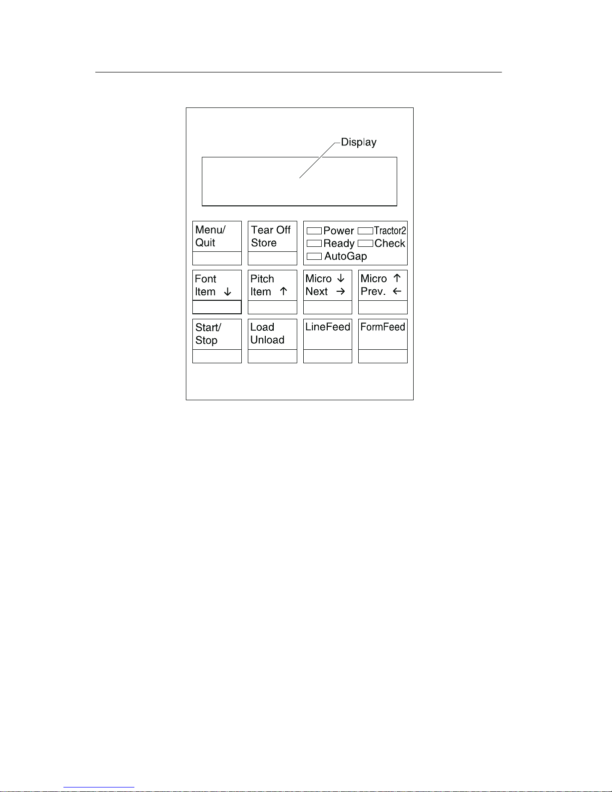
Using the operator p anel
This section provides a brief description of the operator panel
buttons, lights, and settings. Refer to the User’s Guide for additional
information.
Note: Application software may allow the user to operate the printer
from a computer. Changes made to the printer settings from a
software application override settings made from the operator panel,
with the exception of the Font and Pitch Lock features.
Changeable printer functions include:
• Set Top of Form
• Tractor selecti o n
• Character options
• Paper handling options
• Interface options
• Emulation options
• Macro definition and selection
• Print tests
• Auto Gap functions
General information 1-5
4227-300
Using the function menus
Use the Item ↓ and Item ↑ buttons to move through the menu and
option directories. Press Next → to move away from the Main Menu
to the subordinate directories and choices. Press Prev. ← if you want
to go back in a menu or return to the Main Menu.
1-6 S ervice Manual

4227-300
Setting printer functions
1. Press Start/Stop.
2. Press Menu to enter the function menu.
3. Press Item ↓ or Item ↑ until the function menu you want
appears on the display.
Note: The selectable function menu is different depending on the
selected data stream mode (IBM PPDS or Epson emulation) and the
Interface mode (Parallel, RS-232 or RS-422).
4. Press Next → to enter th at menu ite m.
5. Press Item ↓ or Item ↑ until the v alue you want appears on the
display.
6. Press Store to save the selected value.
Note: The currently selected default value is displayed with an
asterisk (*).
If you want to change the optional value in another function menu,
repeat steps 3 through 5. Otherwise, go to the next step.
7. To print the function setting, press It e m ↓ or Item ↑ until the
Print Settings message appears on the display.
8. Press Start/Stop to print the current setting values.
9. Press Quit to exit the function menus.
Note: If you have changed any settings, the printer performs a
Power-On Self Test. For more information, see “Power-On Self Test
(POST)” on page 3-1. If you did not change any settings, the printer
enters the not-ready state.
General information 1-7
4227-300
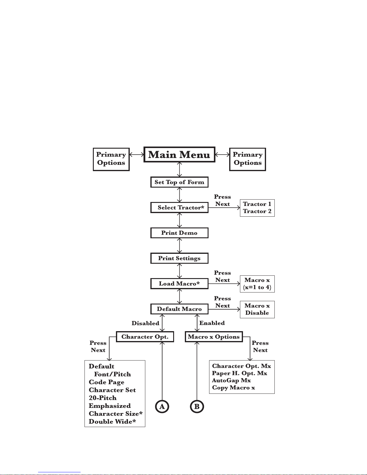
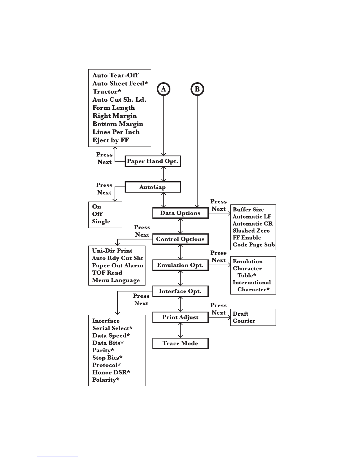
Overview of function menus
Use the Item ↑ and Item ↓ buttons to move through the menu and
option directories. Press Next → to move away from the Main Menu
to the subordinate directories and choices. Press Prev. ← if y o u w a nt
to go back in a menu or return to the Main Menu.
Menu items marked with an asterisk (*) may not appear on the
operator panel, depending on the printer settings or what printer
options are installed.
1-8 S ervice Manual
4227-300
General information 1-9

4227-300
Buttons
When using the function menus, press Item ↓ or Item ↑ to scr o l l
through the menu items. Press Next → or Prev. ← to mov e to th e
next, or previous menu level.
Press To
Menu Enter the function m enu. The printer goes
offline.
Quit • Exit the function menus.
• Run a Powe r-On Self Test ( P O S T).
Tear Off • Adv ance the forms to the tear-off posi tion.
• Retract the forms to the Top-of-Form (TOF)
position when the forms are at the tear-off
position.
Store Save the values select ed in the menus.
Font Select a font.
Item
↓ Scroll down.
Pitch Select a pitch.
Item
↑ Scroll up.
Micro
Next
Micro
Prev.
Start/Stop • To return to Ready and to Start/Stop.
Load/Unload • Load paper (cut or continuous f orms) to t he
↓ Advance the forms down 0.35 mm (1/72 in.).
→ Scroll forward.
↑ Advance the forms up 0.35 mm (1/72 in.).
← Return to the previ ous function menu.
• Load the forms to TOF position with the
ready light on.
TO F position.
• Retract the forms to the tractor position.
LineFeed Advance the paper to the nex t line.
FormFeed • Advance the paper to the T O F position on
1-10 Service Manual
the next page.
• Load the forms to the TOF position.

4227-300
Lights
Light
Power (Green) The printer power is on.
Ready (Green) The printer is online and ready to print.
Check (Yellow) Any of the following conditions may have
Description
The fol lowing con dit ions cause the Ready light
to turn off:
• Pressing Start/Stop
• An end-of-form (EOF)
• A paper jam
• A cover open
• A ha r dw a re er ro r
• A Power-On Self Test failure
• The printer is offline.
occurred:
• An end-of-form (EOF)
• A paper jam
• A cover open
• A ha r dw a re er ro r
• A data transmission error
• An interface mode error
• A Power-On Self Test (POST)
failure
Aut o G ap (Green) Auto Gap is on. Auto Gap automatically adjusts
the printer according to the th ickness of the
paper you ar e u sing.
Tractor 2 (Green) The Tractor 2 Feeder is select ed. (The Tractor
2 Feeder option must be installed. )
General information 1-11

4227-300
1-12 Service Manual

4227-300
2. Diagnostic information
Start
Make a quick visual check for defects (loose or broken part s,
unplugged connectors, or paper jams).
If there is no power after turning the printer on, go to the “Power
failure service check” on page 2-25.
If an error indicator appears, go to the “Error indication table” on
page 2-1 and take the indicated action.
Run the “Print Test” on page 3-5 and refer to the “Error log” on page
3-5 for details of error indication information. If no error indication
appears, refer to “Symptom tables” on page 2-3.
Error indication table
The following table describes the serv ice check entries for the
printer error indication codes.
When an error indication changes after you have entered a service
check, you have an intermittent problem. If this occurs, leave the
servi ce check and go to “Symptom tables” on page 2-3.
Display Indication Description/Action
631 Machine Check
Display RAM Error
632 Machine Check
System RAM Error
Display RAM Read/Write Error. This error
is detected only during POST. Replace the
operator panel.
System RAM Read/Write Error.
Replace the main logic board and
perform the
adjustment” on page 4-3
“Bidirectional print
. Check th e
“Printhead-to-platen gap adjustment”
on page 4-2
.
Diagnostic information 2-1

4227-300
Display Indication Description/ Action
633 Machine Check
Timer Inter r up t Error
636 Machine Check
NOVRAM Error
637 Machine Check
CA Drive Error
638 Machine Check
CA Drive Error
639 Machine Check
CA Drive Error
Timer Interrupt Controller Error. Replace
the main logic board and perform the
“Bidirectional print adjustment” on
page 4-3
platen gap adjustment” on page 4-2
Non-Volat ile Memory Read/Write E rror.
Replace the main log ic board and perform
the
“Bidirectional print adjustment” on
page 4-3
. Check th e “Printhead-to-
.
. Check th e “Printhead-to-
platen gap adjustment” on page 4-2.
Home Timeout Error. Go to the
“Carrier
drive service check” on page 2-15.
Carrier Drive Error.
No emitter pulse detected. Go to the
“Carrier drive service check” on page
2-15.
Carrier Drive Error.
Carrier positioning error. Go to the
“Carrier drive service check” on page
.
2-15
63B Machine Check
Key Scan Error
63C Machine Check
Auto Gap Error
63D Machine Check
Tractor 2 HP Error
63E Machine Check
Head Thermal Error
63F Machine Check
Option RAM Error
640 Machine Check
CA Thermal Error
Button Scann ing Error.
Go to the
check” on page 2-20
Auto Gap Err or.
Go to the
page 2-11
Tractor 2 Home Position Error.
Go to the
“Operator panel service
.
“Auto Gap service check” on
.
“Tractor 2 service check” on
page 2-31.
Head Thermal Sensor Error.
Go to the
service check” on page 2-28
Option RAM Read/Write Error.
Replace the 32Kb Memory Module.
Carrier Thermal Sensor Error.
Go to the
“Print wire drive failure
.
“Carrier drive service check”
on page 2-15.
2-2 S ervice Manual

4227-300
Symptom tables
1. Select the symptom that best describe s the problem.
2. Perform the appropriate action before you go to the indicated
service check.
Diagnostic information 2-3

4227-300
Abnormal Indications
Symptom Action
All LEDs turn on but
do not turn off.
The Power LED is
on, but POST will
not run.
Disconnect the in terf ace c ab le from t he print er and
turn the printer off and then back on. If POST now
runs correctly, the problem is in the computer or
interface cable.
Go to the
“POST serv ice check” on page 2-24.
Abnormal print operation problems
Symptom Action
Printer will not print,
or become Ready.
Abnormal opera ti on,
incorrec t chara cte rs ,
or incorrect line
width
Be sure the interf ace cable is connected pr operly.
Go to th e
“No print or abnormal print ser vice
check” on page 2-19.
Printer is ready but
will not print from the
computer correctly.
Undefined or
incorrect characters
2-4 S ervice Manual

4227-300
Auto Sheet Feeder problems
Symptom Action
Auto Sheet Feed er
will not feed paper.
Auto Sheet Feed er
double feeds.
Auto Sheet Feed er
has intermittent feed
problems.
Paper skews.
Be sure Auto Sheet Feed is set to On i n the Paper
Handling Option Menu.
Be sure the paper select le ver is in the cut sheet
position.
Go to the
2-11
Isolate the problem b y removing the A uto Sheet
Feeder and then feed paper using the man ual
feed tr ay . Go to th e
service check” on page 2-13
6XX Error indications
Symptom Action
6XX Machine
Check is display ed.
Turn the printer off and then on.
Go to
“Auto Gap service check” on page
.
“Auto Sheet Feeder (ASF)
.
“Error indication table” on page 2-1.
Diagnostic information 2-5

4227-300
Paper feed problems
Symptom Action
Paper Empty
Add Paper
is di splayed with
paper in the printe r.
Print operatio n starts
without paper.
Load/Unload
does not function.
Form feed length is
not correct.
Load/Unload
functions with cut
sheets i n use.
Paper feeds, but
Auto Loading does
not work.
Be sure the Pape r Empty Sensor is not blocked.
There may be a problem with the Paper Select
Sensor. Go to the
on page 2-21
Be sure the Paper Select lever is in th e corr ect
position.
There may be a problem with the Paper Select
Sensor. Go to the
“Paper feed service check”
.
“Paper feed service check”
on page 2-21.
Be sure the P a p er Select lev er is in the cut sh eet
position.
Be sure Auto Cut Sheet is enabled in the Paper
Handling Option Menu.
Go to th e
2-21.
“Paper f eed service check” on page
2-6 S ervice Manual
 Loading...