

Page 1

LevelOne
User
Manual
WBR-6005
150Mbps N Wireless
Router
Ver.
1.0
Page 2

WBR-6005 150M N WIRELESS ROUTER
IEEE 802.11n 150 Mbps Wirelesss Gateway Router,
with Four 10/100BASE-TX LAN ports,
and One 10/100BASE-TX WAN port
WBR-6005
E122009-CS-R01
149100000068W
U
SER
G
UID E
Page 3

FEDERAL COMMUNICATION COMMISSION INTERFERENCE STATEMENT
This equipment has been tested and found to comply with the limits for a
Class B digital device, pursuant to Part 15 of the FCC Rules. These limits
are designed to provide reasonable protection against harmful interference
in a residential installation. This equipment generates, uses and
can
radiate
radio frequency energy and, if not installed and used in accordance
with the instructions, may cause harmful interference to radio
communications. This transmitter must not be co-located or operating in
conjunction with any other antenna or transmitter. However, there is no
guarantee that interference will not occur in a particular installation. If this
equipment does cause harmful interference to radio or television reception,
which can be determined by turning the equipment off and on, the user is
encouraged to try to correct the interference by one of the following
measures:
◆
Reorient or relocate the receiving antenna
◆
Increase the separation between the equipment and receiver
◆
Connect the equipment into an outlet on a circuit different from that to
which the receiver is connected
◆
Consult the dealer or an experienced radio/TV technician for help
This device complies with Part 15 of the FCC Rules. Operation is subject to
the following two conditions: (1) This device may not cause harmful
interference, and (2) this device must accept any interference received,
including interference that may cause undesired operation.
FCC Caution: Any changes or modifications not expressly approved by the
party responsible for compliance could void the user's authority to operate
this equipment.
IEEE 802.11b or 802.11g operation of this product in the U.S.A. is
firmware-limited to channels 1 through 11.
IMPORTANT NOTE:
FCC RADIATION EXPOSURE STATEMENT
This equipment complies with FCC radiation exposure limits set forth for an
uncontrolled environment. This equipment should be installed
and
operated
with minimum distance 20 cm between the radiator and your
body.
– 3 –
COMPLIANCES
Page 4

IC STATEMENT
This Class B digital apparatus complies with Canadian ICES-003.
Operation is subject to the following two conditions: (1) this device may
not cause interference, and (2) this device must accept any interference,
including interference that may cause undesired operation of the device.
Cet appareil numérique de la classe B conforme á la norme NMB-003 du
Canada.
The device could automatically discontinue transmission in case of absence
of information to transmit, or operational failure. Note that this is not
intended to prohibit transmission of control or signaling information or the
use of repetitive codes where required by the technology.
IMPORTANT NOTE:
IC RADIATION EXPOSURE STATEMENT:
This equipment complies with IC RSS-102 radiation exposure limits set forth
for an uncontrolled environment. This equipment should be installed and
operated with minimum distance 20 cm between the radiator and your body.
TAIWAN NCC
根據國家通信傳播委員會低功率電波輻射性電機管理辦法規定:
第十二條 經型式認證合格之低功率射頻電機,非經許可,公司、商號或使用者均不得擅自變更
頻率、加大功率或變更原設計之特性及功能。
第十四條 低功率射頻電機之使用不得影響飛航安全及干擾合法通信;經發現有干擾現象時,應
立即停用,並改善至無干擾時方得繼續使用。前項合法通信,指依電信法規定作業之無線電通
信。低功率射頻電機須忍受合法通信或工業、科學及醫療用電波輻射性電機設備之干擾。
EC CONFORMANCE DECLARATION
Marking by the above symbol indicates compliance with the Essential
Requirements of the R&TTE Directive of the European Union (1999/5/EC).
This equipment meets the following conformance standards:
◆
EN 60950-1: 2006 (IEC 60950-1) — Product Safety
◆
EN 55022:2006 + A1:2007, Class B — ITE EMC
◆
EN 55024:1998 + A1:2001 + A2:2003 — ITE EMC
◆
EN 300 328 V1.7.1 (2006-10) — Technical requirements for 2.4 GHz
radio equipment
◆
EN 301 489-1 V1.8.1 (2008-04) — EMC requirements for radio
equipment
◆
EN 301 489-17 V1.3.2 (2008-04) — EMC requirements for radio
equipment
◆
50385 (2002) — Country-specific SAR requirements
– 4 –
C
OMPLIANCES
Page 5

This device is intended for use in the following European Community and
EFTA countries:
◆
Austria
◆
Denmark
◆
Greece
◆
Latvia
◆
Norway
◆
Slovenia
◆
Belgium
◆
Estonia
◆
Hungary
◆
Lithuania
◆
Poland
◆
Spain
◆
Bulgaria
◆
Finland
◆
Iceland
◆
Luxembourg
◆
Portugal
◆
Sweden
◆
Cyprus
◆
France
◆
Ireland
◆
Malta
◆
Romania
◆
Switzerland
◆
Czech Republic
◆
Germany
◆
Italy
◆
Netherlands
◆
Slovakia
◆
United Kingdom
NOTE: The user must use the configuration utility provided with this
product to ensure the channels of operation are in conformance with the
spectrum usage rules for European Community countries as described
below.
◆
This device will automatically limit the allowable channels determined
by the current country of operation. Incorrectly entering the country of
operation may result in illegal operation and may cause harmful
interference to other systems. The user is obligated to ensure the
device is operating according to the channel limitations, indoor/outdoor
restrictions and license requirements for each European Community
country as described in this document.
DECLARATION OF CONFORMITY IN LANGUAGES OF THE EUROPEAN
COMMUNITY
– 5 –
Czech
esky
Manufacturer tímto uje, e tento Radio LAN device je ve shod se základními
poadavky a ími píslunými ustanoveními srnice 1999/5/ES.
Estonian
Eesti
Käesolevaga kinnitab Manufacturer seadme Radio LAN device vastavust direktiivi 1999/
5/EÜ põhinõuetele ja nimetatud direktiivist tulenevatele teistele asjakohastele sätetele.
English
Hereby, Manufacturer, declares that this Radio LAN device is in compliance with the
essential requirements and other relevant provisions of Directive 1999/5/EC.
Finnish
Suomi
Valmistaja Manufacturer vakuuttaa täten että Radio LAN device tyyppinen laite on
direktiivin 1999/5/EY oleellisten vaatimusten ja sitä koskevien direktiivin muiden ehtojen
mukainen.
Dutch
Nederlands
Hierbij verklaart Manufacturer dat het toestel Radio LAN device in overeenstemming is
met de essentiële eisen en de andere relevante bepalingen van richtlijn 1999/5/EG
Bij deze
Manufacturer
dat deze Radio LAN device voldoet aan de essentiële eisen en aan
de overige relevante bepalingen van Richtlijn 1999/5/EC.
French
Français
Par la présente Manufacturer déclare que l'appareil Radio LAN device est conforme aux
exigences essentielles et aux autres dispositions pertinentes de la directive 1999/5/CE
Swedish
Svenska
Härmed intygar Manufacturer att denna Radio LAN device står I
överensstämmelse
med
de väsentliga
egenskapskrav
och övriga relevanta
bestämmelser
som framgår av direktiv
1999/5/EG.
Danish
Dansk
Undertegnede Manufacturer erklæ rer herved, at følgende udstyr Radio LAN device
overholder de væ sentlige krav og øvrige relevante krav i direktiv 1999/5/EF
C
OMPLIANCES
Page 6

– 6 –
German
Deutsch
Hiermit erklärt Manufacturer, dass sich dieser/diese/dieses Radio LAN device in
Ü bereinstimmung mit den grundlegenden Anforderungen und den anderen relevanten
Vorschriften der Richtlinie 1999/5/EG befindet". (BMWi)
Hiermit
erklärt
Manufacturer
die
Ü bereinstimmung
des
Gerätes
Radio LAN device mit den
grundlegenden Anforderungen und den anderen relevanten Festlegungen der Richtlinie
1999/5/EG. (Wien)
Greek
Manufacturer radio LAN device
1999/5/
Hungarian
Magyar
Alulírott, Manufacturer nyilatkozom, hogy a Radio LAN device megfelel a vonatkozó
alapvetõ követelményeknek és az 1999/5/EC irányelv egyéb elõírásainak.
Italian
Italiano
Con la presente Manufacturer dichiara che questo Radio LAN device è conforme ai
requisiti essenziali ed alle altre disposizioni pertinenti stabilite dalla direttiva
Latvian
Latviski
Ar
Manufacturer
deklar, ka Radio LAN device atbilst
Direktvas
1999/5/EK tiskm
prasm un citiem ar to saistajiem noteikumiem.
Lithuanian
Lietuvi
iuo Manufacturer deklaruoja, kad is Radio LAN device atitinka esminius reikalavimus ir
kitas 1999/5/EB Direktyvos nuostatas.
Maltese
Malti
Hawnhekk, Manufacturer, jiddikjara li dan Radio LAN device jikkonforma mal-tiijiet
essenzjali u ma provvedimenti orajn relevanti li hemm fid-Dirrettiva 1999/5/EC.
Spanish
Español
Por medio de la presente Manufacturer declara que el Radio LAN device cumple con los
requisitos esenciales y cualesquiera otras disposiciones aplicables o exigibles de la
Directiva 1999/5/CE
Polish
Polski
Niniejszym Manufacturer owiadcza, Radio LAN device jest zgodny z
zasadniczymi wymogami oraz pozostaymi stosownymi postanowieniami Dyrektywy
Portuguese
Português
Manufacturer declara que este Radio LAN device está conforme com os requisitos
essenciais e outras disposições da Directiva 1999/5/CE.
Slovak
Slovensky
Manufacturer týmto vyhlasuje, e Radio LAN device spa základné vky a tky
prísné ustanovenia Smernice 1999/5/ES.
Slovenian
Slovensko
Manufacturer
izjavlja, da je ta radio LAN device v skladu z
bistvenimi zahtevami
in ostalimi
relevantnimi doloili direktive 1999/5/ES.
C
OMPLIANCES
Page 7

P
URPOSE
This guide gives specific information on how to install the Wireless Router
and its physical and performance related characteristics. It also gives
information on how to operate and use the management functions of the
Wireless Broadband Router.
A
UDIENCE
This guide is for users with a basic working knowledge of computers. You
should be familiar with Windows operating system concepts.
C
ONVENTIONS
The following conventions are used throughout this guide to show
information:
NOTE: Emphasizes important information or calls your attention to related
features or instructions.
C
AUTION
:
Alerts you to a potential hazard that could cause loss of data, or
damage the system or equipment.
W
ARNING
:
Alerts you to a potential hazard that could cause personal injury.
RELATED
P
UBLICATIONS
As part of the Wireless Router‘s software, there is an online web-based
help that describes all management related features.
REVISION
H
ISTORY
This section summarizes the changes in each revision of this guide.
DECEMBER 2009 REVISION
This is the first revision of this guide.
– 7 –
ABOUT THIS GUIDE
Page 8

C
OMPLIANCES
3
ABOUT THIS
G
UIDE
7
C
ONTENTS
8
F
IGURES
12
T
ABLES
14
SECTION I
GETTING
S
TARTED
15
1
I
NTRODUCTION
Key Hardware Features
Description of Capabilities
Applications
Package Contents
Hardware Description
LED Indicators
Ethernet WAN Port
Ethernet LAN Ports
Power Connector
Reset Button
WPS Button
16
16
16
17
18
18
20
21
21
21
22
22
2
NETWORK
P
LANNING
Internet Gateway Router
LAN Access
Point
Wireless Bridge
23
23
24
25
3
INSTALLING THE WIRELESS
R
OUTER
System Requirements
Mounting the Device
Mounting on a Wall
26
26
27
27
–
8 –
CONTENTS
Page 9

Mounting on a Horizontal Surface
Router Mode Connections
Bridge Mode Connections
28
28
29
4
INITIAL
C
ONFIGURATION
ISP Settings
Connecting to the Login Page
Home Page and Main Menu
Common Web Page Buttons
Setup Wizard
Step 1 - Language Selection
Step 2 - Time Settings
Step 3 - WAN Settings - DHCP
Step 3 - WAN Settings - Static IP
Step 3 - WAN Settings - PPPoE
Step 3 - WAN Settings - PPTP
Step 3 - WAN Settings - L2TP
Step 4 - Wireless Security
Completion
31
31
31
32
33
33
33
34
35
36
37
38
40
41
42
SECTION II
WEB
C
ONFIGURATION
43
5
OPERATION
M
ODE
Logging In
Operation Mode
44
45
47
6
INTERNET
S
ETTINGS
WAN Setting
DHCP
Static IP
PPPoE
PPTP
L2TP
LAN Setting DHCP
Clients Advanced
Routing
Advanced Routing Settings
48
48
49
50
51
53
55
57
59
60
60
– 9 –
C
ONTENTS
Page 10

Routing Table
Dynamic Route
61
62
7
WIRELESS
C
ONFIGURATION
Basic Settings
HT Physical Mode Settings
Advanced Settings
Advanced Wireless
Wi-Fi Multimedia
Multicast-to-Unicast Converter
WLAN Security
Wired Equivalent Privacy (WEP)
WPA Pre-Shared Key
WPA Enterprise Mode
IEEE 802.1X and RADIUS
Access Policy
Wireless Distribution System (WDS)
Wi-Fi Protected Setup (WPS)
Station List
63
63
66
67
67
69
72
73
74
75
76
78
80
80
83
86
8
FIREWALL
C
ONFIGURATION
MAC/IP/Port Filtering
Current Filter
Rules
Virtual Server Settings (Port Forwarding)
Current Virtual Servers in system
DMZ
System Security
Content Filtering
87
87
89
90
91
91
92
93
9
ADMINISTRATION
S
ETTINGS
System Management
Time Zone Settings
DDNS Settings
Firmware Upgrade
Configuration Settings
System Status
Statistics
System Log
95
96
97
98
99
100
101
103
104
–
10
–
C
ONTENTS
Page 11

SECTION III
A
PPENDICES
105
A
T
ROUBLESHOOTING
Diagnosing LED Indicators
If You Cannot Connect to the Internet
Before Contacting Technical Support
106
106
106
107
B
HARDWARE
S
PECIFICATIONS
108
C
CABLES AND
P
INOUTS
Twisted-Pair Cable Assignments
10/100BASE-TX Pin Assignments
Straight-Through Wiring
Crossover Wiring
110
110
111
111
112
D
LICENSE
I
NFORMATION
The GNU General Public License
113
113
G
LOSSARY
117
I
NDEX
121
– 11 –
C
ONTENTS
Page 12

Figure 1:
Figure
2:
Figure
3:
Figure
4:
Figure
5:
Figure
6:
Figure
7:
Figure
8:
Figure
9:
Figure
10:
Figure
11:
Figure
12:
Figure
13:
Figure
14:
Figure
15:
Figure
16:
Figure
17:
Figure
18:
Figure
19:
Figure
20:
Figure
21:
Figure
22:
Figure
23:
Figure
24:
Figure
25:
Figure
26:
Figure
27:
Figure
28:
Figure
29:
Figure
30:
Figure
31:
Top Panel
Rear Panel
LEDs
Operating as an Internet Gateway Router
Operating as an Access Point
Operating as a Wireless Bridge
Operating as a Wireless Repeater
Wall Mounting
Router Mode Connection
Bridge Mode Connection
Login Page
Home Page
Wizard Step 1 - Language Selection
Wizard Step 2 - Time and SNTP Settings
Wizard Step 3 - WAN Settings - DHCP
Wizard Step 3 - WAN Settings - Static IP
Wizard Step 3 - WAN Settings - PPPoE
Wizard Step 3 - WAN Settings - PPTP
Wizard Step 3 - WAN Settings - L2TP
Wizard Step 4 - Wireless Security
Logging On
Home Page
Operation Mode
DHCP Configuration
Static IP Configuration
PPPoE Configuration
PPTP Configuration
L2TP Configuration
LAN Configuration
DHCP Clients
Advanced Routing (Router Mode)
19
20
20
23
24
25
25
27
28
29
32
32
33
34
35
36
37
38
40
41
45
46
47
49
50
51
53
55
57
59
60
– 12 –
FIGURES
Page 13

Figure 32:
Figure 33:
Figure 34:
Figure 35:
Figure 36:
Figure 37:
Figure 38:
Figure 39:
Figure 40:
Figure 41:
Figure 42:
Figure 43:
Figure 44:
Figure 45:
Figure 46:
Figure 47:
Figure 48:
Figure 49:
Figure 50:
Figure 51:
Figure 52:
Figure 53:
Figure 54:
Figure 55:
Figure 56:
Figure 57:
Figure 58:
Figure 59:
Figure 60:
Figure 61:
Figure 62:
Figure 63:
Figure 64:
Figure 65:
Basic Settings
HT Physical Mode Settings
Advanced Wireless Settings
Wi-Fi Multimedia Settings
WMM Configuration
Multicast-to-Unicast Converter
Security Mode Options
Security Mode - WEP
Security Mode - WPA-PSK
Security Mode - WPA
Security Mode - 802.1X
Access Policy
Manual WDS MAC Address Configuration
WDS Configuration Example
WDS Configuration
Enabling WPS
WPS Configuration
Station List
MAC/IP/Port Filtering
Virtual Server
DMZ
System Security
Content Filtering
System Management
Time Zone Settings
DDNS Settings (Router Mode)
Firmware Upgrade
Configuration Settings
System Status (Router Mode)
Statistics
System Log
RJ-45 Connector
Straight-through Wiring
Crossover Wiring
64
66
67
70
71
72
73
74
75
77
79
80
81
81
82
84
84
86
88
90
91
92
93
96
97
98
99
100
101
103
104
110
112
112
– 13 –
F
IGURES
Page 14

Table 1:
Table 2:
Table 3:
Table 4:
Table 5:
Key Hardware Features
LED Behavior
WMM Access Categories
LED Indicators
10/100BASE-TX MDI and MDI-X Port Pinouts
16
21
70
106
111
– 14 –
TABLES
Page 15

This section provides an overview of the Wireless Router, and describes
how to install and mount the unit. It also describes the basic settings
required to access the management interface and run the setup Wizard.
This section includes these chapters:
◆
―Introduction‖ on page 16
◆
―Network Planning‖ on page 23
◆
―Initial Configuration‖ on page 31
◆
―Installing the Wireless Router‖ on page 26
– 15 –
S
ECTION
I
GETTING STARTED
Page 16

The 150M N Wireless Router (WBR-6005) supports routing from an
Internet Service Provider (ISP) connection (DSL or cable modem) to a local
network. It is simple to configure and can be up and running in minutes.
KEY HARDWARE
F
EATURES
The following table describes the main hardware features of the Wireless
Router.
Table 1: Key Hardware Features
WAN Port
One 100BASE-TX RJ-45 port for connecting to the Internet.
4 LAN Ports
Four 100BASE-TX RJ-45 ports for local network connections.
WPS Button
To set up a secure connection to a wireless device.
Reset Button
For resetting the unit and restoring factory defaults.
LEDs
Provides LED indicators for Power, WAN port, LAN ports, WLAN,
and WPS status.
Mounting Options
Can be mounted on any horizontal surface such as a desktop or
shelf, or on a wall using two screws.
DESCRIPTION OF
C
APABILITIES
◆
Internet connection through an RJ-45 WAN port.
◆
Local network connection through four 10/100 Mbps Ethernet ports.
◆
DHCP for dynamic IP configuration.
◆
Firewall with Stateful Packet Inspection, client privileges, intrusion
detection, and NAT.
◆
NAT also enables multi-user Internet access via a single user account,
and virtual server functionality (providing protected access to Internet
services such as Web, FTP, e-mail, and Telnet).
◆
VPN passthrough (IPsec, PPTP, or L2TP).
◆
User-definable application sensing tunnel supports applications
requiring multiple connections.
– 16 –
Feature Description
1
INTRODUCTION
Page 17

◆
Easy setup through a Web browser on any operating system that
supports TCP/IP.
◆
Compatible with all popular Internet applications.
In addition, the Wireless Router offers full network management
capabilities through an easy-to-configure web interface.
APPLICATIONS
Many advanced networking features are provided by the Wireless Router:
◆
Wired LAN — The Wireless Router provides connectivity to wired
10/100 Mbps devices, making it easy to create a network in small
offices or homes.
◆
Internet Access — This device supports Internet access through a
WAN connection. Since many DSL providers use PPPoE to establish
communications with end users, the Wireless Router includes built-in
clients for these protocols, eliminating the need to install these services
on your computer.
◆
Shared IP Address — The Wireless Router provides Internet access
for up to 253 users via a single shared IP address. Using only one ISP
account, multiple users on your network can browse the Web at the
same time.
◆
Virtual Server — If you have a fixed IP address, you can set the
Wireless Router to act as a virtual host for network address translation.
Remote users access various services at your site using a constant IP
address. Then, depending on the requested service (or port number),
the Wireless Router can route the request to the appropriate server (at
another internal IP address). This secures your network from direct
attack by hackers, and provides more flexible management by allowing
you to change internal IP addresses without affecting outside access to
your network.
◆
DMZ Host Support — Allows a networked computer to be fully
exposed to the Internet. This function is used when NAT and firewall
security prevent an Internet application from functioning correctly.
◆
Security — The Wireless Router supports security features that deny
Internet access to specified users, or filter all requests for specific
services the administrator does not want to serve. WPA (Wi-Fi
Protected Access) and MAC filtering provide security over the wireless
network.
◆
Virtual Private Network (VPN) Passthrough — The Wireless Router
supports the passthrough of three of the most commonly used VPN
protocols – IPsec, PPTP, and L2TP. These protocols allow remote users
to establish a secure connection to their corporate network. If your
service provider supports VPNs, then these protocols can be used to
create an authenticated and encrypted tunnel for passing secure data
over the Internet (i.e., a traditionally shared data network). The VPN-
– 17 –
C
HAPTER
1 | Introduction
Description of Capabilities
Page 18

passthrough protocols supported by the Wireless Router are briefly
described below.
Internet Protocol Security — IPsec encrypts and authenticates
entire IP packets and encapsulates them into new IP packets for
secure communications between networks.
■
Point-to-Point Tunneling Protocol — Provides a secure tunnel
for remote client access to a PPTP security gateway. PPTP includes
provisions for call origination and flow control required by ISPs.
■
Layer 2 Tunneling Protocol — L2TP merges the best features of
PPTP and the Layer 2 Forwarding (L2F) protocol. Like PPTP, L2TP
requires that the ISP‘s routers support the protocol.
■
PACKAGE
C
ONTENTS
The Wireless Router package includes:
◆
WBR-6005 150M N Wireless Router
◆
RJ-45 Category 5 network cable
◆
AC power adapter
◆
Quick Installation Guide
Inform your dealer if there are any incorrect, missing or damaged parts. If
possible, retain the carton, including the original packing materials. Use
them again to repack the product in case there is a need to return it.
– 18 –
C
HAPTER
1 | Introduction
Package Contents
Page 19

HARDWARE
D
ESCRIPTION
The Wireless Router connects to the Internet using its RJ-45 WAN port. It
connects directly to your PC or to a local area network using its RJ-45 Fast
Ethernet LAN ports.
The Wireless Router includes an LED display on the front panel for system
power and port indications that simplifies installation and network
troubleshooting.
Figure 1:
Top Panel
– 19 –
C
HAPTER
1 | Introduction
Hardware Description
Page 20
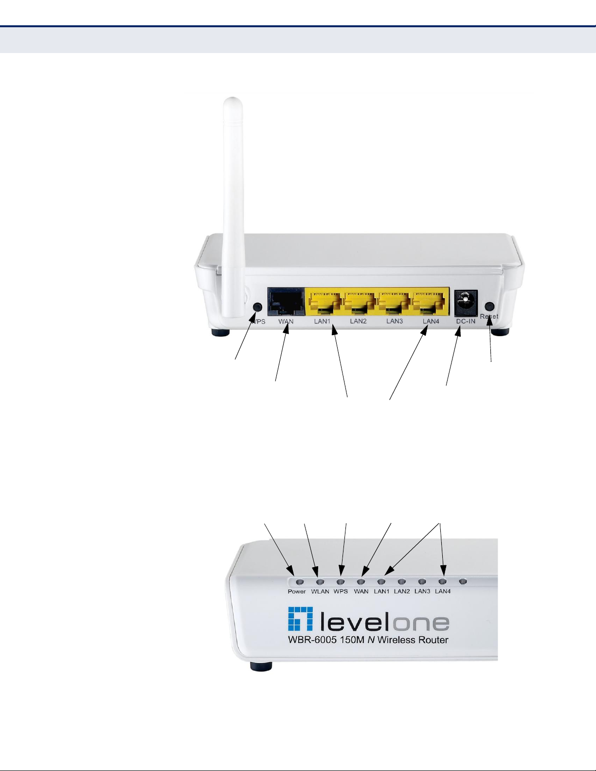
Figure 2:
Rear Panel
WPS Button
Reset Button
RJ-45 WAN Port
DC Power
Socket
RJ-45 LAN Ports
LED INDICATORS
The Wireless Router includes eight status LED indicators, as described in
the following figure and table.
Figure 3: LEDs
WPS
WAN
LAN 1~4
Power
WLAN
– 20 –
C
HAPTER
1 | Introduction
Hardware Description
Page 21

Table 2: LED Behavior
Power
On Blue
The unit is receiving power and is operating
normally.
Off
There is no power currently being supplied to
the unit.
WLAN
On/Blinking Blue
The 802.11n radio is enabled and
transmitting
or
receiving
data
through
wireless
links.
Off
The 802.11n radio is disabled.
WPS
Blinking
WPS authentication is in progress.
Off
WPS authentication is not in progress.
WAN
On Blue
The Ethernet WAN port is aquiring an IP
address.
Blinking
The Ethernet WAN port is connected and is
transmitting/receiving data.
Off
The Ethernet WAN port is disconnected or has
malfunctioned.
LAN1~LAN4
On Blue
The Ethernet LAN port is connected to a PC or
server.
Blinking
The Ethernet port is connected and is
transmitting/receiving data.
Off
The Ethernet port is disconnected or has
malfunctioned.
ETHERNET WAN PORT
A 100BASE-TX RJ-45 port that can be attached to an Internet access
device, such as a DSL or Cable modem.
ETHERNET LAN
PORTS
The Wireless Router has four 100BASE-TX RJ-45 ports that can be attached
directly to 10BASE-T/100BASE-TX LAN segments.
These port support automatic MDI/MDI-X operation, so you can use
straight-through cables for all network connections to PCs, switches, or
hubs.
POWER CONNECTOR
The Wireless Router must be powered with its supplied power adapter.
Failure to do so results in voiding of any warrantly supplied with the
product. The power adapter automatically adjusts to any voltage between
100~240 volts at 50 or 60 Hz, and supplies 5 volts DC power to the unit.
No voltage range settings are required.
– 21 –
LED Status Description
C
HAPTER
1 | Introduction
Hardware Description
Page 22

RESET BUTTON
This button is used to restore the factory default configuration. If you hold
down the button for 5 seconds or more, any configuration changes you
may have made are removed, and the factory default configuration is
restored to the Wireless Router.
WPS BUTTON
Press to automatically configure the Wireless Router with other WPS
devices in the WLAN.
– 22 –
C
HAPTER
1 | Introduction
Hardware Description
Page 23
The Wireless Router is designed to be very flexible in its deployment
options. It can be used as an Internet gateway for a small network, or as
an access point to extend an existing wired network to support wireless
users. It also supports use as a wireless bridge to connect up to four wired
LANs.
This chapter explains some of the basic features of the Wireless Router and
shows some network topology examples in which the device is
implemented.
INTERNET GATEWAY
R
OUTER
The Wireless Router can connect directly to a cable or DSL modem to
provide an Internet connection for multiple users through a single service
provider account. Users connect to the Wireless Router either through a
wired connection to a LAN port, or though the device‘s own wireless
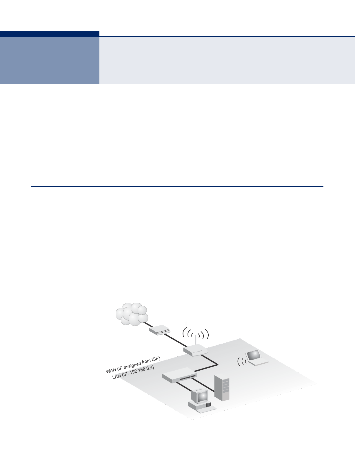
network. The Wireless Router functions as an Internet gateway when set to
Router Mode.
An Internet gateway employs several functions that essentially create two
separate Internet Protocol (IP) subnetworks; a private internal network
with wired and wireless users, and a public external network that connects
to the Internet. Network traffic is forwarded, or routed, between the two
subnetworks.
Figure 4: Operating as an Internet Gateway Router
Internet
Service
Provider
Cable/DSL
Modem
Wireless AP/Router
Notebook PC
(IP: 192.168.0.x)
LAN Switch
Server
(IP: 192.168.0.x)
Desktop PC
(IP: 192.168.0.x)
– 23 –
2
NETWORK PLANNING
Page 24
The private local network, connected to the LAN port or wireless interface,
provides a Dynamic Host Configuration Protocol (DHCP) server for
allocating IP addresses to local PCs and wireless clients, and Network
Address Translation (NAT) for mapping the multiple ―internal‖ IP addresses
to one ―external‖ IP address.
The public external network, connected to the WAN port, supports DHCP
client, Point-to-Point Protocol over Ethernet (PPPoE) and static IP for
connection to an Internet service provider (ISP) through a cable or DSL
modem.
LAN ACCESS
P
OINT
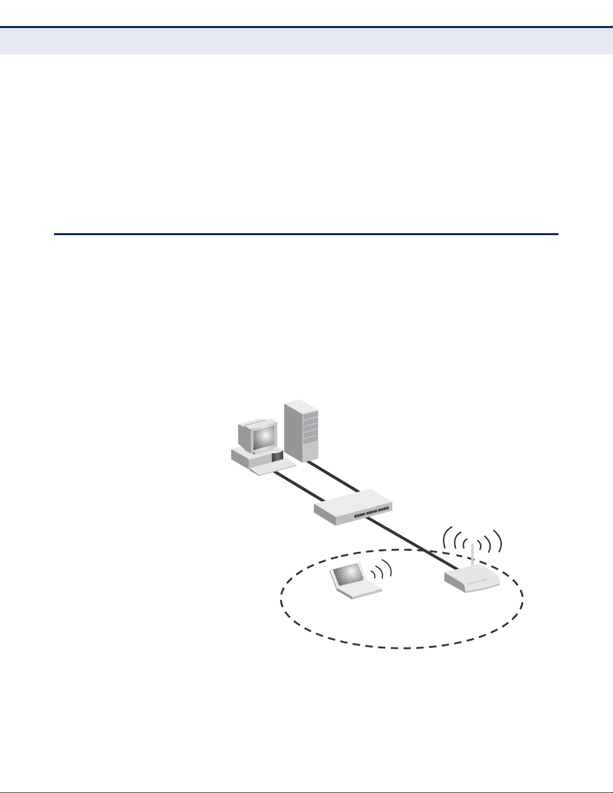
The Wireless Router can provide an access point service for an existing
wired LAN, creating a wireless extension to the local network. The Wireless
Router functions as purely an access point when set to Bridge Mode. When
used in this mode, there are no gateway functions between the WAN port
and the LAN and wireless interface.
A Wi-Fi wireless network is defined by its Service Set Identifier (SSID) or
network name. Wireless clients that want to connect to a network must set
their SSID to the same SSID of the network service.
Figure 5: Operating as an Access Point
Server
(IP: 192.168.0.x)
Desktop PC
(IP: 192.168.0.x)
LAN Switch
Wireless
AP/Router
Notebook PC
(IP: 192.168.0.x)
– 24 –
C
HAPTER
2 | Network Planning
LAN Access Point
Page 25
WIRELESS
B
RIDGE
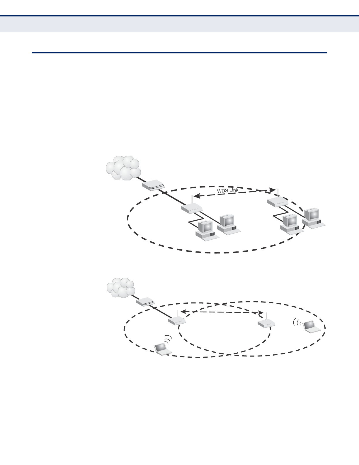
The IEEE 802.11 standard defines a Wireless Distribution System (WDS)
for bridge connections between access points. The Wireless Router can use
WDS to forward traffic on links between units.
Up to four WDS links can be specified for the Wireless Router.
The WDS feature enables two basic functions to be configured in the
wireless network. Either a repeater function that extends the range of the
wireless network, or a bridge function that connects a remote LAN segment
to an Internet connection.
Figure 6: Operating as a Wireless Bridge
Internet
Service
Provider
Cable/DSL
Modem
Gateway Router
(Bridge Mode)
Gateway Router
(Router Mode)
Desktop PCs
Desktop PCs
Figure 7: Operating as a Wireless Repeater
Internet
Service
Provider
Cable/DSL
Modem
WDS Link
Gateway Router
(Router Mode)
Gateway Router
(Bridge Mode)
Notebook PC
Notebook PC
–
25 –
C
HAPTER
2 | Network Planning
Wireless Bridge
Page 26

The Wireless Router has two basic operating modes that can be set
through the web-based management interface. For information on setting
the mode suitable for your network environment. See ―Operation Mode‖ on
page 47.
◆
Router Mode — A gateway mode that connects a wired LAN and
wireless clients to an Internet access device, such as a cable or DSL
modem. This is the factory set default mode.
◆
Bridge Mode — An access point mode that extends a wired LAN to
wirelessclients.
In addition to these basic operating modes, the wireless interface supports
Wireless Distribution System (WDS) links to other Wireless Routers. These
advanced configurations are not described in this section. See ―Network
Planning‖ on page 23 for more information.
In a basic configuration, how the Wireless Router is connected depends on
the operating mode. The sections in this chapter describe connections for
basic Router Mode and Bridge Mode operation.
SYSTEM
R
EQUIREMENTS
You must meet the following minimum requirements:
◆
An Internet access device (DSL or Cable modem) with an Ethernet port
connection.
◆
An up-to-date web browser: Internet Explorer 6.0 or above or Mozilla
Firefox 2.0 or above.
– 26 –
3
INSTALLING THE WIRELESS ROUTER
Page 27
MOUNTING THE
D
EVICE
The Wireless Router can be mounted on any horizontal surface, or on a
wall. The following sections describe the mounting options.
MOUNTING ON A WALL
The Wireless Router should be mounted only to a wall or wood surface that
is at least 1/2-inch plywood or its equivalent. To mount the unit on a wall,
always use its wall-mounting slots. The unit must be mounted with the RJ45 cable connector oriented upwards to ensure proper operation.
Figure 8:
Wall Mounting
Mounting Slots
To mount on a wall, follow the instructions below.
1.
Mark the position of the two screw holes on the wall. For concrete or
brick walls, you will need to drill holes and insert wall plugs for the
screws.
2.
Insert two 20-mm M4 tap screws (not included) into the holes, leaving
about 2~3 mm (0.08~0.12 inches) clearance from the wall.
3.
Line up the two mounting points on the unit with the screws in the wall,
then slide the unit down onto the screws until it is in a secured position.
– 27 –
C
HAPTER
3 | Installing the Wireless Router
Mounting the Device
Page 28

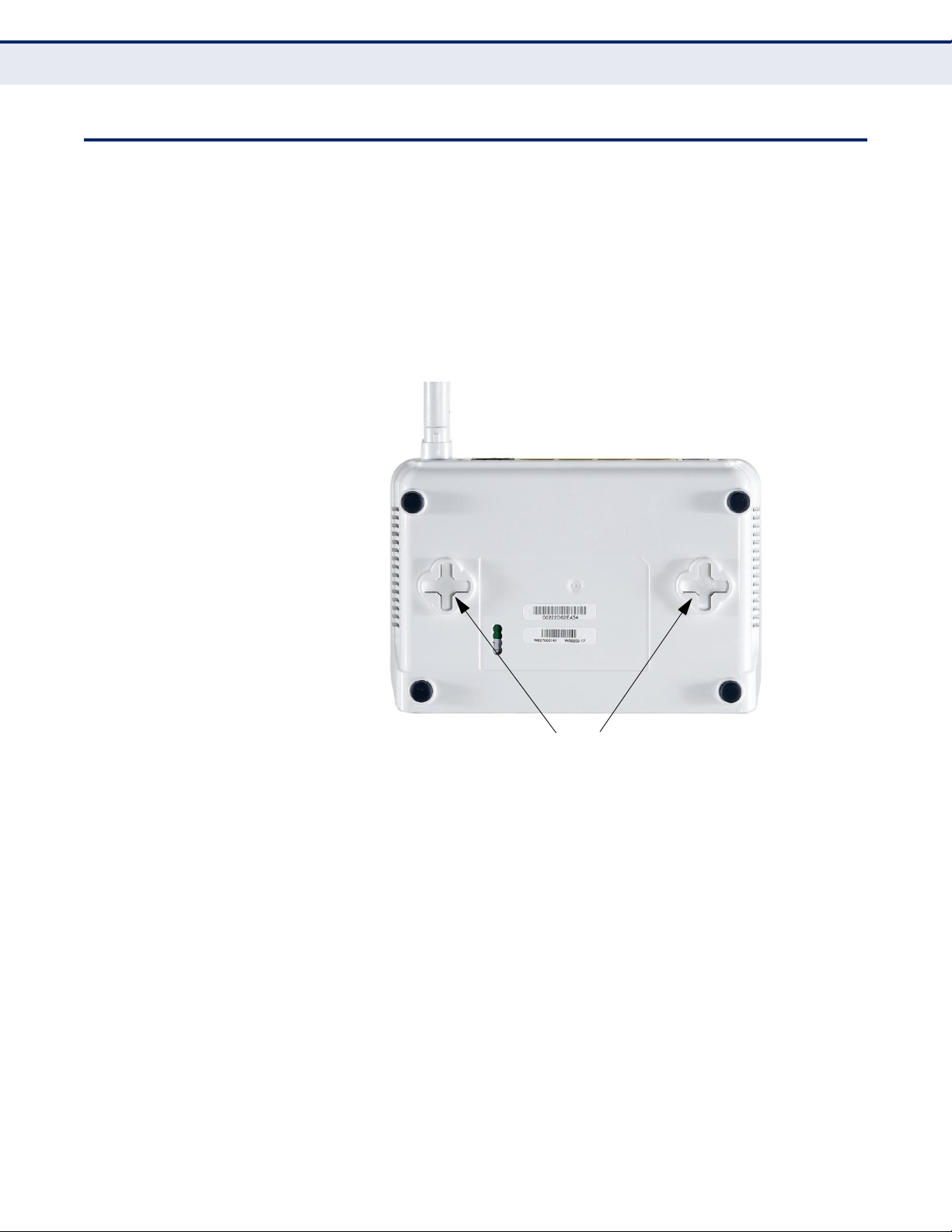
MOUNTING ON A To keep the Wireless Router from sliding on the surface, the Wireless
HORIZONTAL SURFACE
Router has four rubber feet on the bottom of the unit.
It is recommended to select an uncluttered area on a sturdy surface, such
as a desktop or table. The unit can also be protected by securing all
attached cables to a table leg or other nearby fixed structure.
ROUTER MODE
C
ONNECTIONS
In its default Router Mode, the Wireless Router forwards traffic between an
Internet connected cable or DSL modem, and wired or wireless PCs or
notebooks. The basic connections are illustrated in the figure below.
Figure 9: Router Mode Connection
4.
Set up wireless
devices
Notebook PC
1.
Connect WAN port to
cable/DSL modem
Internet
3.
Connect AC power
adapter to power source
Cable/DSL Modem
2.
Connect LAN port
to PC
To connect the Wireless Router in Router Mode for use as an Internet
gateway, follow these steps:
1.
Connect an Ethernet cable from the Wireless Router‘s WAN port to your
Internet connected cable or DSL modem.
2.
Connect an Ethernet cable from the Wireless Router‘s LAN ports to your
PCs. Alternatively, you can connect to a workgroup switch to support
more wired users. The Wireless Router can support up to 253 wired and
wireless users.
3.
Power on the Wireless Router by connecting the AC power adapter and
plugging it into a power source.
C
AUTION
:
Use ONLY the power adapter supplied with the Wireless Router.
Otherwise, the product may be damaged.
When you power on the Wireless Router, verify that the Power LED
turns on and that the other LED indicators start functioning as
described under see ―LED Indicators‖ on page 20.
– 28 –
C
HAPTER
3 | Installing the Wireless Router
Router Mode Connections
Page 29
4. Set up wireless devices by pressing the WPS button on the Wireless
Router or by using the web interface. See ―Initial Configuration‖ on
page 31 for more information on accessing the web interface.
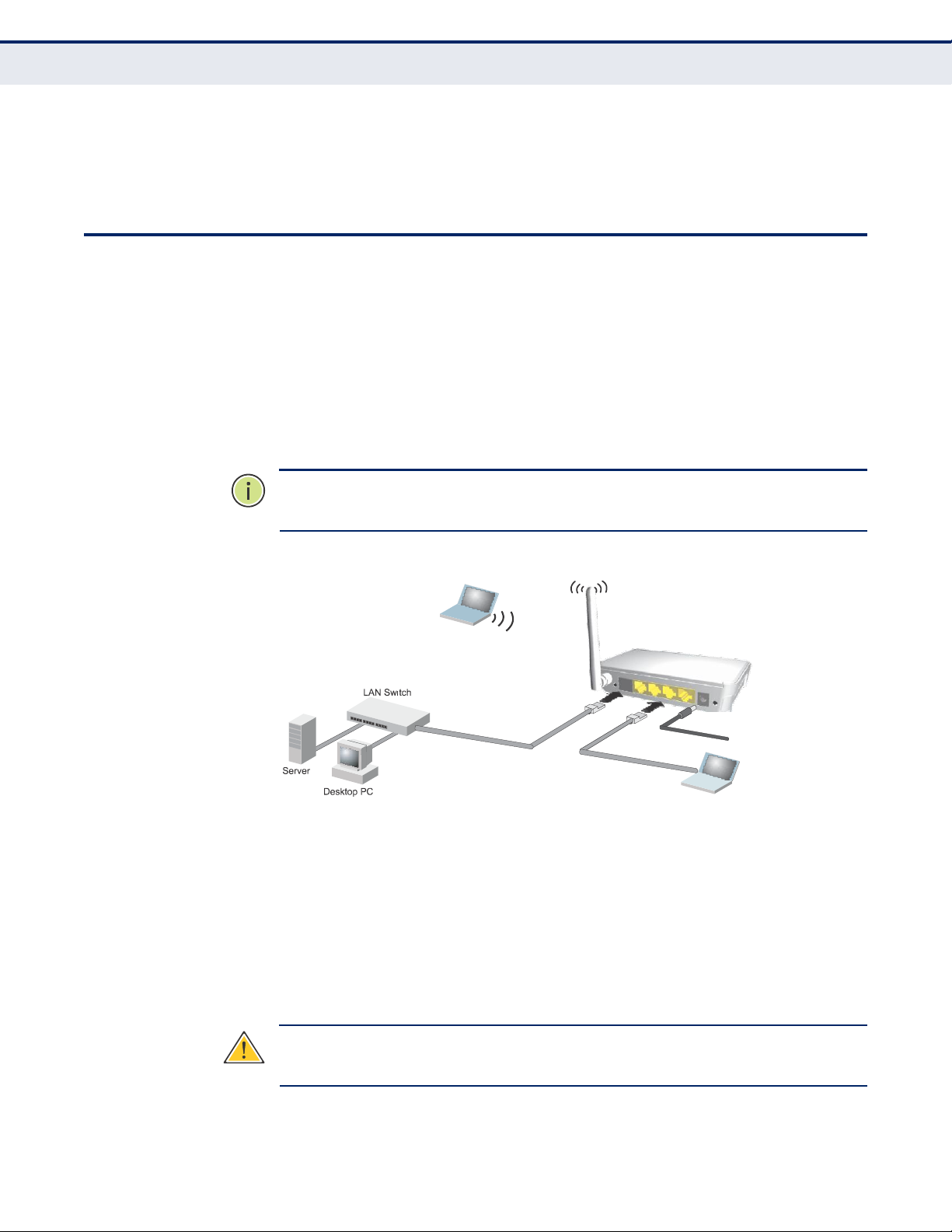
BRIDGE MODE
C
ONNECTIONS
In Bridge Mode, the Wireless Router operates as a wireless access point,
extending a local wired network to associated wireless clients (PCs or
notebooks with wireless capability). From any nearby location, you can
then make a wireless connection to the Wireless Router and access the
wired network resources, including local servers and the Internet.
In Bridge Mode, the Wireless Router does not support gateway functions on
its WAN port. Both the LAN port and the WAN ports can be connected to a
local Ethernet LAN.
NOTE: Bridge Mode is not the factory default mode and must be manually
set using the web management interface.
Figure 10: Bridge Mode Connection
4.
Set up wireless
devices
Notebook PC
2.
Connect AC power
adapter to power source
1.
Connect LAN and WAN ports
to PCs or an Ethernet LAN switch
3.
Connect LAN port
to PC
To connect the Wireless Router for use as an access point, follow these
steps:
1. Using Ethernet cable connect the Wireless Router‘s LAN and WAN ports
to PCs or a LAN switch.
2. Power on the Wireless Router by connecting the AC power adapter and
plugging it into a power source.
C
AUTION
:
Use ONLY the power adapter supplied with the Wireless Router.
Otherwise, the product may be damaged.
– 29 –
C
HAPTER
3 | Installing the Wireless Router
Bridge Mode Connections
Page 30

When you power on the Wireless Router, verify that the Power LED turns on
and that the other LED indicators start functioning as described under ―LED
Indicators‖ on page 20.
3.
Connect an Ethernet cable from the Wireless Router‘s LAN ports to your
PCs. Alternatively, you can connect to a workgroup switch to support
more wired users. The Wireless Router can support up to 253 wired and
wireless users
4.
Set up wireless devices by pressing the WPS button on the Wireless
Router or by using the web interface. See ―Initial Configuration‖ on
page 31 for more information on accessing the web interface.
– 30 –
C
HAPTER
3 | Installing the Wireless Router
Bridge Mode Connections
Page 31

The Wireless Router offers a user-friendly web-based management
interface for the configuration of all the unit‘s features. Any PC directly
attached to the unit can access the management interface using a web
browser, such as Internet Explorer (version 6.0 or above).
ISP
S
ETTINGS
If you are not sure of your connection method, please contact your
Internet Service Provider. There are several connection types to choose
from: Static IP, DHCP (cable connection), PPPoE (DSL connection), PPTP,
and L2TP.
NOTE: If using the PPPoE option, you will need to remove or disable any
PPPoE client software on your computers.
CONNECTING TO THE LOGIN
P
AGE
It is recommended to make initial configuration changes by connecting a
PC directly to one of the Wireless Router‘s LAN ports. The Wireless Router
has a default IP address of 192.168.0.1 and a subnet mask of
255.255.255.0. You must set your PC IP address to be on the same subnet
as the Wireless Router (that is, the PC and Wireless Router addresses must
both start 192.168.0.x).
To access the Wireless Router‘s management interface, follow these steps:
1. Use your web browser to connect to the management interface using
the default IP address of 192.168.0.1.
2. Log into the interface by entering the default username ―admin‖ and
password ―password,‖ then click Login.
NOTE: It is strongly recommended to change the default user name and
password the first time you access the web interface. For information on
changing user names and passwords, See ―System Management‖ on
page 96.
– 31 –
4
INITIAL CONFIGURATION
Page 32

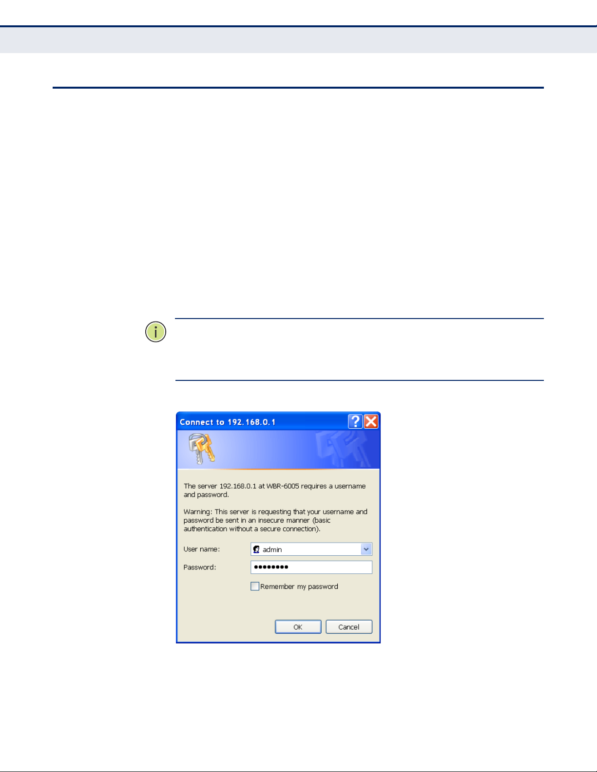
Figure 11:
Login Page
HOME PAGE AND MAIN
M
ENU
After logging in to the web interface, the Home page displays. The Home
page shows the main menu and the method to access the Setup Wizard.
Figure 12:
Home Page
–
32 –
C
HAPTER
4 | Initial Configuration
Home Page and Main Menu
Page 33

COMMON WEB PAGE
B
UTTONS
The list below describes the common buttons found on most web
management pages:
◆
Apply – Applies the new parameters and saves them to memory. Also
displays a screen to inform you when it has taken affect. Clicking
‗Apply‘ returns to the home page.
◆
Cancel – Cancels the newly entered settings and restores the previous
settings.
◆
Next – Proceeds to the next step.
◆
Previous – Returns to the previous screen.
SETUP
W
IZARD
The Wizard is designed to help you configure the basic settings required to
get the the Wireless Router up and running. There are only a few basic
steps you need to set up the the Wireless Router and provide a connection.
Follow these steps:
STEP 1 - LANGUAGE
SELECTION
Select between English, Traditional Chinese, or Simple Chinese. Click Next
to proceed to the next step of the wizard.
Figure 13: Wizard Step 1 - Language Selection
The following items are displayed on the first page of the Setup Wizard:
◆
Select Language — Selects English, Traditional Chinese, or Simple
Chinese as the interface language.
– 33 –
C
HAPTER
4 | Initial Configuration
Common Web Page Buttons
Page 34

STEP 2 - TIME
SETTINGS
The Step 2 page of the Wizard configures time zone and SNTP settings.
Select a time zone according to where the device is operated. Click Next
after completing the setup.
Figure 14: Wizard Step 2 - Time and SNTP Settings
The following items are displayed on this page:
◆
Current Time — Receives a time and date stamp from an SNTP server.
◆
Time Zone — Select the time zone that is applicable to your region.
◆
SNTP Server — Enter the address of an SNTP server to receive time
updates.
◆
SNTP synchronization (hours) — Specify the interval between SNTP
server updates.
– 34 –
C
HAPTER
4 | Initial Configuration
Setup Wizard
Page 35

STEP 3 - WAN
SETTINGS - DHCP
The Step 3 page of the Wizard specifies the Internet connection
parameters for the Wireless Router‘s WAN port. Click Next after completing
the setup.
By default, the access point WAN port is configured with DHCP enabled.
The options are Static IP, DHCP (cable modem), PPPoE (DSL modem),
PPTP, and L2TP. Each option changes the parameters that are displayed on
the page.
Figure 15: Wizard Step 3 - WAN Settings - DHCP
The following items are displayed on this page:
◆
WAN Connection Type — Select the connection type for the WAN port
from the drop down list. (Default: DHCP)
◆
Hostname — Specifies the host name of the DHCP client.
(Default: WBR-6005)
◆
Primary DNS Server — The IP address of the Primary Domain Name
Server. A DNS maps numerical IP addresses to domain names and can
be used to identify network hosts by familiar names instead of the IP
addresses. To specify a DNS server, type the IP addresses in the text
field provided. Otherwise, leave the text field blank.
◆
Secondary DNS Server — The IP address of the Secondary Domain
Name Server.
◆
MAC Clone — Some ISPs limit Internet connections to a specified MAC
address of one PC, which is registered with the ISP. This setting allows
you to manually change the MAC address of the Wireless Router's WAN
interface to match the PC's MAC address provided to your ISP for
registration. You can enter the registered MAC address manually by
typing it in the boxes provided. Otherwise, connect only the PC with the
registered MAC address to the Wireless Router, then click the ―Clone
your PC‘s MAC Address‖. (Default: Disabled)
– 35 –
C
HAPTER
4 | Initial Configuration
Setup Wizard
Page 36
NOTE: If you are unsure of the PC MAC address originally registered by
your ISP, call your ISP and request to register a new MAC address for your
account. Register the default MAC address of the Wireless Router.
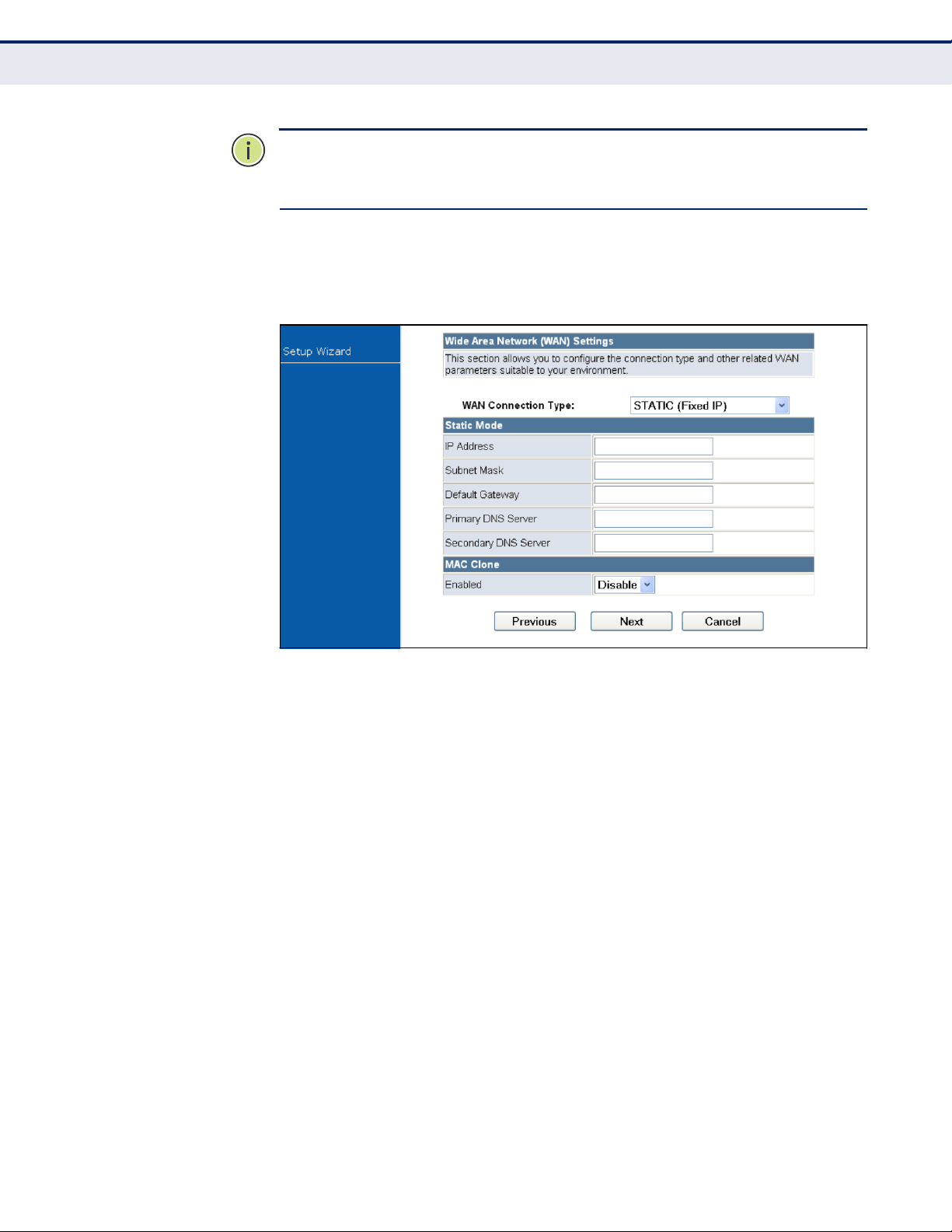
STEP 3 - WAN
SETTINGS - STATIC IP
Configures a static IP for the WAN port.
Figure 16: Wizard Step 3 - WAN Settings - Static IP
The following items are displayed on this page:
◆
WAN Connection Type — Select the connection type for the WAN port
from the drop down list. (Default: DHCP)
◆
IP Address — The IP address of the Wireless Router. Valid IP
addresses consist of four decimal numbers, 0 to 255, separated by
periods.
◆
Subnet Mask — The mask that identifies the host address bits used for
routing to specific subnets.
◆
Default Gateway — The IP address of the gateway router for the
Wireless Router, which is used if the requested destination address is
not on the local subnet.
◆
Primary DNS Server — The IP address of the Primary Domain Name
Server. A DNS maps numerical IP addresses to domain names and can
be used to identify network hosts by familiar names instead of the IP
addresses. To specify a DNS server, type the IP addresses in the text
field provided. Otherwise, leave the text field blank.
◆
Secondary DNS Server — The IP address of the Secondary Domain
Name Server.
– 36 –
C
HAPTER
4 | Initial Configuration
Setup Wizard
Page 37
◆
MAC Clone — Some ISPs limit Internet connections to a specified MAC
address. This setting allows you to manually change the MAC address
of the Wireless Router's WAN interface to match the PC's MAC address
provided to your ISP for registration. You can enter the registered MAC
address manually by typing it in the boxes provided. Otherwise,
connect only the PC with the registered MAC address to the Wireless
Router, then click the ―Clone your PC‘s MAC Address‖ (Default: Disable)
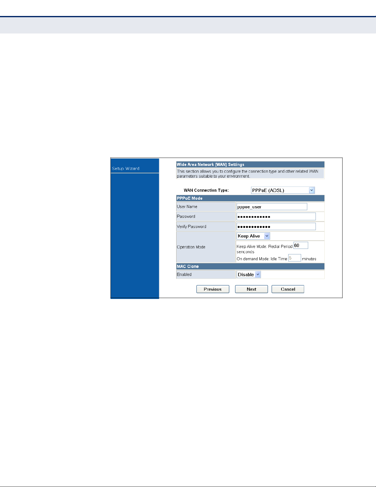
STEP 3 - WAN
SETTINGS - PPPOE
Enable the Wireless Router IP address to be assigned automatically from
an Internet service provider (ISP) through a DSL modem using Point-toPoint Protocol over Ethernet (PPPoE).
Figure 17:
Wizard Step 3 - WAN Settings - PPPoE
The following items are displayed on this page:
◆
User Name — Sets the PPPoE user name for the WAN port.
(Default: pppoe_user; Range: 1~32 characters)
◆
Password — Sets a PPPoE password for the WAN port.
(Default: pppoe_password; Range: 1~32 characters)
◆
Verify Password — Prompts you to re-enter your chosen password.
◆
Operation Mode — Enables and configures the keep alive time and
configures the on-demand idle time.
◆
MAC Clone — Some ISPs limit Internet connections to a specified MAC
address of one PC. This setting allows you to manually change the MAC
address of the Wireless Router's WAN interface to match the PC's MAC
address provided to your ISP for registration. You can enter the
registered MAC address manually by typing it in the boxes provided.
Otherwise, connect only the PC with the registered MAC address to the
– 37 –
C
HAPTER
4 | Initial Configuration
Setup Wizard
Page 38
Wireless Router, then click the ―Clone your PC‘s MAC Address‖ (Default:
Disable)
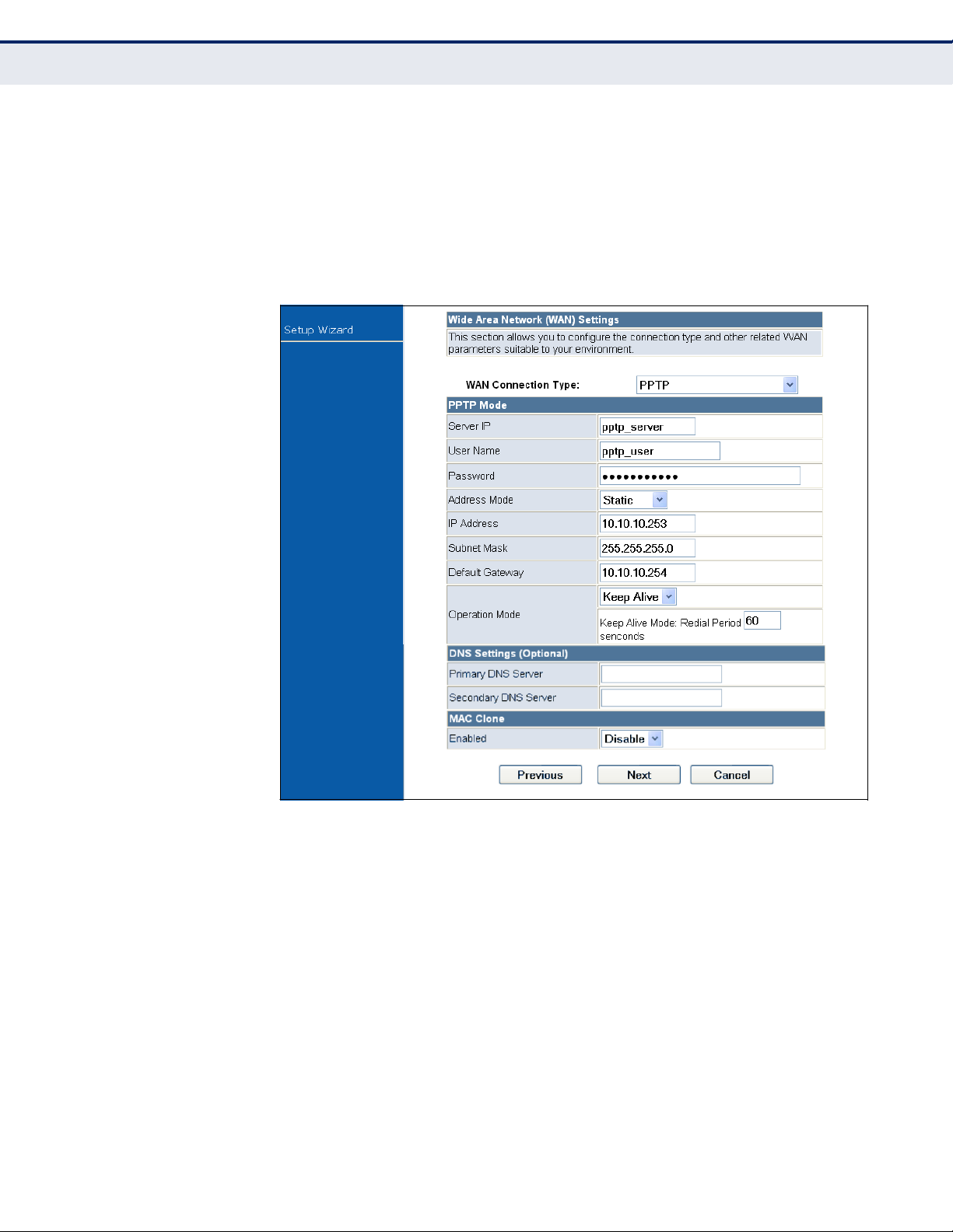
STEP 3 - WAN
SETTINGS - PPTP
Enables the Point-to-Point Tunneling Protocol (PPTP) for implementing
virtual private networks. The service is provided in many European
countries.
Figure 18:
Wizard Step 3 - WAN Settings - PPTP
The following items are displayed on this page:
◆
Server IP — Sets the PPTP server IP Address. (Default: pptp_server)
◆
User Name — Sets the PPTP user name for the WAN port.
(Default: pptp_user; Range: 1~32 characters)
◆
Password — Sets a PPTP password for the WAN port. (Default:
pptp_password; Range: 1~32 characters)
◆
Verify Password — Prompts you to re-enter your chosen password.
◆
Address Mode — Sets a PPTP network mode. (Default: Static)
◆
IP Address — Sets the static IP address. (Default: 0.0.0.0, available
when PPTP Network Mode is set to static IP.)
– 38 –
C
HAPTER
4 | Initial Configuration
Setup Wizard
Page 39

◆
Subnet Mask — Sets the static IP subnet mask. (Default:
255.255.255.0, available when PPTP Network Mode is set to static IP.)
◆
Default Gateway — The IP address of a router that is used when the
requested destination IP address is not on the local subnet.
◆
Operation Mode — Enables and configures the keep alive time.
◆
Primary DNS Server — The IP address of the Primary Domain Name
Server. A DNS maps numerical IP addresses to domain names and can
be used to identify network hosts by familiar names instead of the IP
addresses. To specify a DNS server, type the IP addresses in the text
field provided. Otherwise, leave the text field blank.
◆
Secondary DNS Server — The IP address of the Secondary Domain
Name Server.
◆
MAC Clone — Some ISPs limit Internet connections to a specified MAC
address of one PC. This setting allows you to manually change the MAC
address of the Wireless Router's WAN interface to match the PC's MAC
address provided to your ISP for registration. You can enter the
registered MAC address manually by typing it in the boxes provided.
Otherwise, connect only the PC with the registered MAC address to the
Wireless Router, then click the ―Clone your PC‘s MAC Address‖ (Default:
Disable)
– 39 –
C
HAPTER
4 | Initial Configuration
Setup Wizard
Page 40
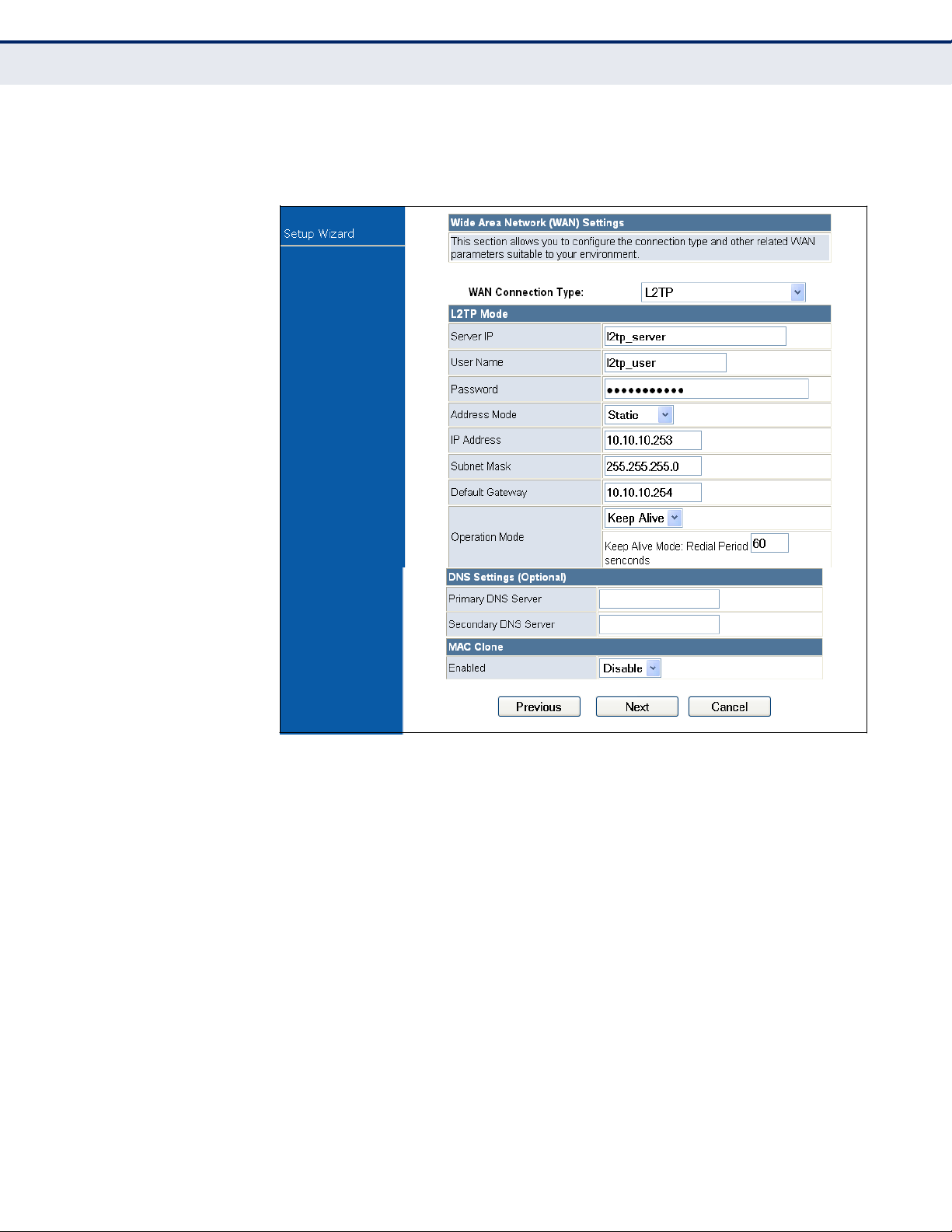
STEP 3 - WAN
SETTINGS - L2TP
Enables the Layer 2 Tunneling Protocol (L2TP) for implementing virtual
private networks. The service is provided in many European countries.
Figure 19:
Wizard Step 3 - WAN Settings - L2TP
The following items are displayed on this page:
◆
Server IP — Sets the L2TP server IP Address. (Default: l2tp_server)
◆
User Name — Sets the L2TP user name for the WAN port.
(Default: l2tp_user; Range: 1~32 characters)
◆
Password — Sets a L2TP password for the WAN port. (Default:
l2tp_password; Range: 1~32 characters)
◆
Verify Password — Prompts you to re-enter your chosen password.
◆
Address Mode — Sets a L2TP network mode. (Default: Static)
◆
IP Address — Sets the static IP address. (Default: 0.0.0.0, available
when L2TP Network Mode is set to static IP.)
◆
Subnet Mask — Sets the static IP subnet mask. (Default:
255.255.255.0, available when L2TP Network Mode is set to static IP.)
– 40 –
C
HAPTER
4 | Initial Configuration
Setup Wizard
Page 41

◆
Default Gateway — The IP address of a router that is used when the
requested destination IP address is not on the local subnet.
◆
Operation Mode — Enables and configures the keep alive time.
◆
Primary DNS Server — The IP address of the Primary Domain Name
Server. A DNS maps numerical IP addresses to domain names and can
be used to identify network hosts by familiar names instead of the IP
addresses. To specify a DNS server, type the IP addresses in the text
field provided. Otherwise, leave the text field blank.
◆
Secondary DNS Server — The IP address of the Secondary Domain
Name Server.
◆
MAC Clone — Some ISPs limit Internet connections to a specified MAC
address of one PC. This setting allows you to manually change the MAC
address of the Wireless Router's WAN interface to match the PC's MAC
address provided to your ISP for registration. You can enter the
registered MAC address manually by typing it in the boxes provided.
Otherwise, connect only the PC with the registered MAC address to the
Wireless Router, then click the ―Clone your PC‘s MAC Address‖ (Default:
Disable)
STEP 4 - WIRELESS
SECURITY
The Step 4 page of the Wizard configures the wireless network name and
security options.
Figure 20: Wizard Step 4 - Wireless Security
The following items are displayed on this page:
◆
SSID Choice — The name of the wireless network service provided by
the Wireless Router. Clients that want to connect to the network must
set their SSID to the same as that of the Wireless Router.
(Default: ―LevelOne‖)
– 41 –
C
HAPTER
4 | Initial Configuration
Setup Wizard
Page 42

◆
Security Mode — Specifies the security mode for the SSID. Select the
security method and then configure the required parameters. For more
information, see ―WLAN Security‖ on page 73. (Options: Disabled,
Open, Shared,
WEP-AUTO,
WPA-PSK, WPA2-PSK, WPA-PSK_WPA2-PSK,
WPA, WPA2, WPA1_WPA2, 802.1X; Default: Disabled)
NOTE: To keep your wireless network protected and secure, you should
implement the highest security possible. For small networks, it is
recommended to select WPA2-PSK using AES encryption as the most
secure option. However, if you have older wireless devices in the network
that do not support AES encryption, select TKIP as the encryption
algorithm.
◆
Access Policy — The Wireless Router provides a MAC address filtering
facility. The access policy can be set to allow or reject specific station
MAC addresses. This feature can be used to connect known wireless
devices that may not be able to support the configured security mode.
◆
Add a station MAC — Enter the MAC address of the station that you
want to filter. MAC addresses must be entered in the format
xx:xx:xx:xx:xx:xx.
COMPLETION
After completion of the Wizard, the screen returns to the Home Page.
– 42 –
C
HAPTER
4 | Initial Configuration
Setup Wizard
Page 43

This section provides details on configuring the Wireless Router using the
web browser interface.
This section includes these chapters:
◆
―Operation Mode‖ on page 44
◆
―Internet Settings‖ on page 48
◆
―Wireless Configuration‖ on page 63
◆
―Firewall Configuration‖ on page 87
◆
―Administration Settings‖ on page 95
– 43 –
S
ECTION
II
WEB CONFIGURATION
Page 44

The Wireless Router offers a user-friendly web-based management
interface for the configuration of all the unit‘s features. Any PC directly
attached to the unit can access the management interface using a web
browser, such as Internet Explorer (version 6.0 or above).
The following sections are contained in this chapter:
◆
―Logging In‖ on page 45
◆
―Operation Mode‖ on page 47
– 44 –
5
OPERATION MODE
Page 45
LOGGING
I
N
It is recommended to make initial configuration changes by connecting a
PC directly to one of the Wireless Router's LAN ports. The Wireless Router
has a default IP address of 192.168.0.1 and a subnet mask of
255.255.255.0. If your PC is set to ―Obtain an IP address automatically‖
(that is, set as a DHCP client), you can connect immediately to the web
interface. Otherwise, you must set your PC IP address to be on the same
subnet as the Wireless Router (that is, the PC and Wireless Router
addresses must both start 192.168.0.x).
To access the configuration menu, follow these steps:
1. Use your web browser to connect to the management interface using
the default IP address of 192.168.0.1.
2. Log into the Wireless Router management interface by entering the
default user name ―admin‖ and password ―password,‖ then click OK.
NOTE: It is strongly recommended to change the default user name and
password the first time you access the web interface. For information on
changing user names and passwords, see ―Administration Settings‖ on
page 95.
Figure 21:
Logging On
–
45 –
C
HAPTER
5 | Operation Mode
Logging In
Page 46

The home page displays the main menu items at the top of the screen and
the Setup Wizard. See ―Setup Wizard‖ on page 33.
Figure 22:
Home Page
NOTE: The displayed pages and settings may differ depending on whether
the unit is in Router or Bridge Mode. See ―Operation Mode‖ on page 47.
– 46 –
C
HAPTER
5 | Operation Mode
Logging In
Page 47

OPERATION
M
ODE
The Operation Mode Configuration page allows you to set up the mode
suitable for your network environment.
Figure 23: Operation Mode
The following items are displayed on this page:
◆
Bridge Mode — An access point mode that extends a wired LAN to
wireless clients.
◆
Router Mode — The internet gateway mode that connects a wired LAN
and wireless clients to an Internet access device, such as a cable or
DSL modem. This is the factory set default mode.
– 47 –
C
HAPTER
5 | Operation Mode
Operation Mode
Page 48

The Internet Settings pages allow you to manage basic system
configuration settings. It includes the following sections:
◆
―WAN Setting‖ on page 48
―DHCP‖ on page 49
■
―Static IP‖ on page 50
■
―PPPoE‖ on page 51
■
―PPTP‖ on page 53
■
―L2TP‖ on page 55
■
◆
―LAN Setting‖ on page 57
◆
―DHCP Clients‖ on page 59
◆
―Advanced Routing‖ on page 60
NOTE: In Bridge mode, the Wireless Router‘s Internet Settings options are
significantly reduced, with only LAN Settings and the Client List being
available to the user.
WAN
S
ETTING
The WAN Setting page specifies the Internet connection parameters. Click
on ―Internet Settings‖ followed by ―WAN‖.
◆
WAN Connection Type — By default, the access point WAN port is
configured with DHCP enabled. After you have network access to the
access point, you can use the web browser interface to modify the
initial IP configuration, if needed. The options are Static IP, DHCP (cable
modem), PPPoE (DSL modem), and PPTP. Each option changes the
parameters displayed below it. (Default: DHCP).
– 48 –
6
INTERNET SETTINGS
Page 49
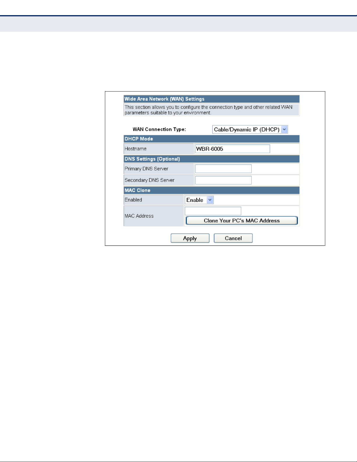
DHCP
Enables Dynamic Host Configuration Protocol (DHCP) for the WAN port.
This setting allows the Wireless Router to automatically obtain an IP
address from a DHCP server normally operated by the Internet Service
Provider (ISP).
Figure 24:
DHCP Configuration
The following items are displayed on this page:
◆
Hostname (Optional) — The hostname of the DHCP client.
◆
Primary DNS Server — The IP address of the Primary Domain Name
Server. A DNS maps numerical IP addresses to domain names and can
be used to identify network hosts by familiar names instead of the IP
addresses. To specify a DNS server, type the IP addresses in the text
field provided. Otherwise, leave the text field blank.
◆
Secondary DNS Server — The IP address of the Secondary Domain
Name Server.
◆
MAC Clone — Some ISPs limit Internet connections to a specified MAC
address of one PC. This setting allows you to manually change the MAC
address of the Wireless Router's WAN interface to match the PC's MAC
address provided to your ISP for registration. You can enter the
registered MAC address manually by typing it in the boxes provided.
Otherwise, connect only the PC with the registered MAC address to the
Wireless Router, then click the ―Clone your PC‘s MAC Address‖ (Default:
Disable)
– 49 –
C
HAPTER
6 | Internet Settings
WAN Setting
Page 50

NOTE: If you are unsure of the PC MAC address originally registered by
your ISP, call your ISP and request to register a new MAC address for your
account. Register the default MAC address of the Wireless Router.
STATIC IP
Configures a static IP for the WAN port.
Figure 25:
Static IP Configuration
The following items are displayed on this page:
◆
IP Address — The IP address of the Wireless Router. Valid IP
addresses consist of four decimal numbers, 0 to 255, separated by
periods.
◆
Subnet Mask — The mask that identifies the host address bits used for
routing to specific subnets.
◆
Default Gateway — The IP address of the gateway router for the
Wireless Router, which is used if the requested destination address is
not on the local subnet.
◆
Primary DNS Server — The IP address of the Primary Domain Name
Server on the network. A DNS maps numerical IP addresses to domain
names and can be used to identify network hosts by familiar names
instead of the IP addresses. If you have one or more DNS servers
located on the local network, type the IP addresses in the text fields
provided. Otherwise, leave the addresses as all zeros (0.0.0.0).
– 50 –
C
HAPTER
6 | Internet Settings
WAN Setting
Page 51
◆
Secondary DNS Server — The IP address of the Secondary Domain
Name Server on the network.
◆
MAC Clone — Some ISPs limit Internet connections to a specified MAC
address of one PC. This setting allows you to manually change the MAC
address of the Wireless Router‘s WAN interface to match the PC‘s MAC
address provided to your ISP for registration. You can enter the
registered MAC address manually by typing it in the boxes provided.
Otherwise, connect only the PC with the registered MAC address to the
Wireless Router, then click the ―Clone your PC‘s MAC Address‖ (Default:
Disable)
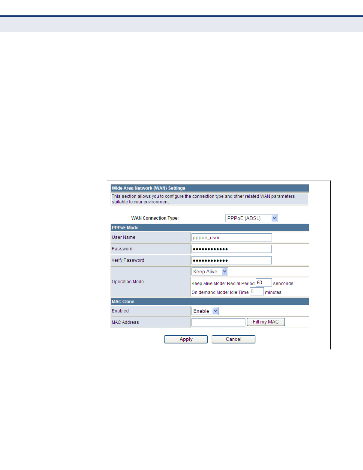
PPPOE
Enables the Wireless Router IP address to be assigned automatically from
an Internet service provider (ISP) through a DSL modem using Point-toPoint Protocol over Ethernet (PPPoE).
Figure 26:
PPPoE Configuration
The following items are displayed on this page:
◆
PPPoE User Name — Sets the PPPoE user name for the WAN port.
(Default: pppoe_user; Range: 1~32 characters)
◆
PPPoE Password — Sets a PPPoE password for the WAN port.
(Default: pppoe_password; Range: 1~32 characters)
◆
Verify Password — Prompts you to re-enter your chosen password.
– 51 –
C
HAPTER
6 | Internet Settings
WAN Setting
Page 52

◆
Operation Mode — Selects the operation mode as Keep Alive, On
Demand or Manual. (Default: Keep Alive)
Keep Alive Mode: The Wireless Router will periodically check your
Internet connection and automatically re-establish your connection
when disconnected. (Default: 60 seconds)
■
On Demand Mode: The maximum length of inactive time the unit
will stay connected to the DSL service provider before
disconnecting. (Default: 5 minutes)
■
◆
MAC Clone — Some ISPs limit Internet connections to a specified MAC
address of one PC. This setting allows you to manually change the MAC
address of the Wireless Router's WAN interface to match the PC's MAC
address provided to your ISP for registration. You can enter the
registered MAC address manually by typing it in the boxes provided.
Otherwise, connect only the PC with the registered MAC address to the
Wireless Router, then click the ―Clone your PC‘s MAC Address‖ (Default:
Disable)
– 52 –
C
HAPTER
6 | Internet Settings
WAN Setting
Page 53
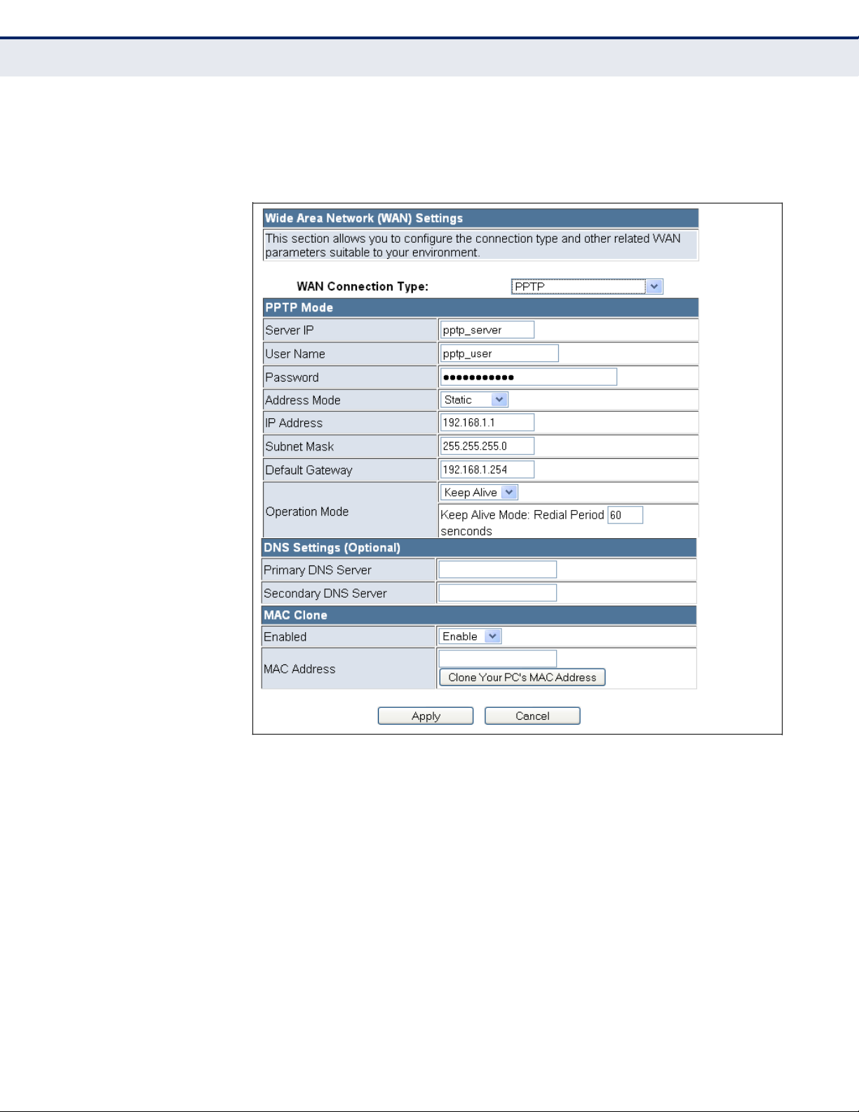
PPTP
Enables the Point-to-Point Tunneling Protocol (PPTP) for implementing
virtual private networks. The service is provided in many European
countries.
Figure 27:
PPTP Configuration
The following items are displayed on this page:
◆
Server IP — Sets a PPTP server IP Address. (Default: pptp_server)
◆
User Name — Sets the PPTP user name for the WAN port. (Default:
pptp_user; Range: 1~32 characters)
◆
Password — Sets a PPTP password for the WAN port. (Default:
pptp_password; Range: 1~32 characters)
◆
Verify Password — Prompts you to re-enter your chosen password.
◆
Address Mode — Sets a PPTP network mode. (Default: Static)
– 53 –
C
HAPTER
6 | Internet Settings
WAN Setting
Page 54

◆
IP Address — Sets the static IP address. (Default: 0.0.0.0, available
when PPTP Network Mode is set to static IP.)
◆
Subnet Mask — Sets the static IP subnet mask. (Default:
255.255.255.0, available when PPTP Network Mode is set to static IP.)
◆
Default Gateway — The IP address of the gateway router for the
Wireless Router, which is used if the requested destination address is
not on the local subnet.
◆
Operation Mode — Selects the operation mode as Keep Alive, or
Manual. (Default: Keep Alive)
Keep Alive Mode: The Wireless Router will periodically check your
Internet connection and automatically re-establish your connection
when disconnected. (Default: 60 seconds)
■
Manual Mode: The unit will remain connected to the Internet
without disconnecting.
■
◆
Primary DNS Server — The IP address of the Primary Domain Name
Server. A DNS maps numerical IP addresses to domain names and can
be used to identify network hosts by familiar names instead of the IP
addresses. To specify a DNS server, type the IP addresses in the text
field provided. Otherwise, leave the text field blank.
◆
Secondary DNS Server — The IP address of the Secondary Domain
Name Server.
◆
MAC Clone — Some ISPs limit Internet connections to a specified MAC
address of one PC. This setting allows you to manually change the MAC
address of the Wireless Router's WAN interface to match the PC's MAC
address provided to your ISP for registration. You can enter the
registered MAC address manually by typing it in the boxes provided.
Otherwise, connect only the PC with the registered MAC address to the
Wireless Router, then click the ―Clone your PC‘s MAC Address‖ (Default:
Disable)
– 54 –
C
HAPTER
6 | Internet Settings
WAN Setting
Page 55

L2TP
Enables the Layer 2 Tunneling Protocol (L2TP) for implementing virtual
private networks. The service is provided in many European countries.
Figure 28:
L2TP Configuration
The following items are displayed on this page:
◆
Server IP — Sets the L2TP server IP Address. (Default: l2tp_server)
◆
User Name — Sets the L2TP user name for the WAN port.
(Default: l2tp_user; Range: 1~32 characters)
◆
Password — Sets a L2TP password for the WAN port. (Default:
l2tp_password; Range: 1~32 characters)
◆
Verify Password — Prompts you to re-enter your chosen password.
◆
Address Mode — Sets a L2TP network mode. (Default: Static)
– 55 –
C
HAPTER
6 | Internet Settings
WAN Setting
Page 56

◆
IP Address — Sets the static IP address. (Default: 0.0.0.0, available
when L2TP Network Mode is set to static IP.)
◆
Subnet Mask — Sets the static IP subnet mask. (Default:
255.255.255.0, available when L2TP Network Mode is set to static IP.)
◆
Default Gateway — The IP address of the gateway router for the
Wireless Router, which is used if the requested destination address is
not on the local subnet.
◆
Operation Mode — Selects the operation mode as Keep Alive, or
Manual. (Default: Keep Alive)
Keep Alive Mode: The Wireless Router will periodically check your
Internet connection and automatically re-establish your connection
when disconnected. (Default: 60 seconds)
■
Manual Mode: The unit will remain connected to the Internet
without disconnecting.
■
◆
Primary DNS Server — The IP address of the Primary Domain Name
Server. A DNS maps numerical IP addresses to domain names and can
be used to identify network hosts by familiar names instead of the IP
addresses. To specify a DNS server, type the IP addresses in the text
field provided. Otherwise, leave the text field blank.
◆
Secondary DNS Server — The IP address of the Secondary Domain
Name Server.
◆
MAC Clone — Some ISPs limit Internet connections to a specified MAC
address of one PC. This setting allows you to manually change the MAC
address of the Wireless Router's WAN interface to match the PC's MAC
address provided to your ISP for registration. You can enter the
registered MAC address manually by typing it in the boxes provided.
Otherwise, connect only the PC with the registered MAC address to the
Wireless Router, then click the ―Clone your PC‘s MAC Address‖ (Default:
Disable)
– 56 –
C
HAPTER
6 | Internet Settings
WAN Setting
Page 57
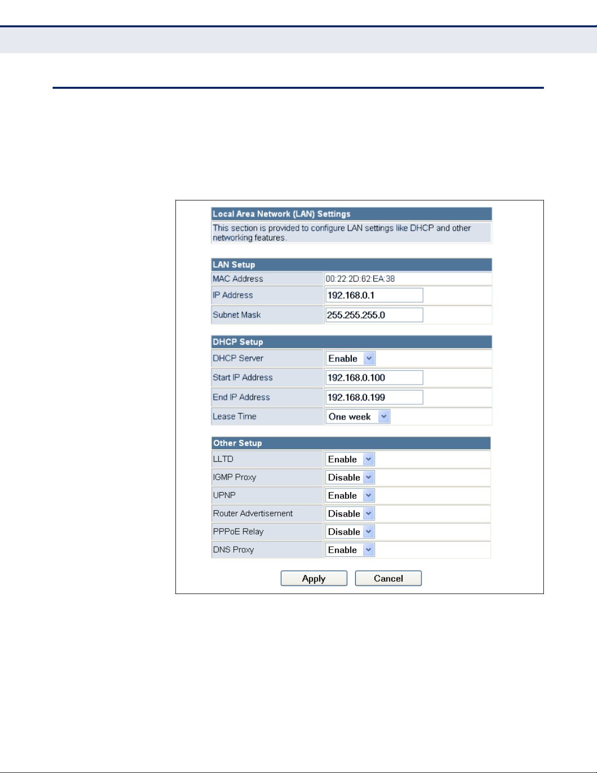
LAN
S
ETTING
The Wireless Router must have a valid IP address for management using a
web browser and to support other features. The unit has a default IP
address of 192.168.0.1. You can use this IP address or assign another
address that is compatible with your existing local network. Click on
―Internet Settings‖ followed by ―LAN.‖
Figure 29:
LAN Configuration
The following items are displayed on this page:
◆
LAN IP Address — Valid IP addresses consist of four decimal
numbers, 0 to 255, separated by periods. The default setting is
192.168.0.1.
◆
Subnet Mask — Indicate the local subnet mask. (Default:
255.255.255.0.)
– 57 –
C
HAPTER
6 | Internet Settings
LAN Setting
Page 58

◆
MAC Address — The shared physical layer address for the Wireless
Router‘s LAN ports.
◆
DHCP Server — Enable this feature to assign IP settings to wired and
wireless clients connected to the Wireless Router. The IP address,
subnet mask, default gateway, and Domain Name Server (DNS)
address are dynamically assigned to clients. (Options: Enable, Disable;
Default: Enable)
◆
Start/End IP Address — Specify the start and end IP addresses of a
range that the DHCP server can allocate to DHCP clients. Note that the
address pool range is always in the same subnet as the unit‘s IP
setting. The maximum clients that the unit can support is 253.
◆
Primary DNS Server — The IP address of Domain Name Servers on
the network. A DNS maps numerical IP addresses to domain names
and can be used to identify network hosts by familiar names instead of
the IP addresses.
◆
Secondary DNS Server — The IP address of the Secondary Domain
Name Server on the network.
◆
Default Gateway — The default gateway is the IP address of the
router for the Wireless Router, which is used if the requested
destination address is not on the local subnet.
◆
Lease Time — Select a time limit for the use of an IP address from the
IP pool. When the time limit expires, the client has to request a new IP
address. The lease time is expressed in seconds. (Options: Forever, Two
weeks, One week, Two days, One day, Half day, Two hours, One hour,
Half hour; Default: One week)
◆
Statically Assigned — Up to three devices with specific MAC
addresses can be assigned static IP addresses. That is, the DHCP server
always assigns these devices the same IP addresses.
◆
LLTD — Link Layer Topology Discovery (LLTD) is a Microsoft proprietary
discovery protocol which can be used for both wired and wireless
networks. (Options: Disable/Enable, Default: Enable)
◆
IGMP Proxy — Enables IGMP proxy on the Wireless Router. (Options:
Disable/Enable, Default: Disable)
◆
UPNP — Allows the device to advertise its UPnP capabilities. (Default:
Enable)
◆
Router Advertisement — Enables the sending and receiving of
routing advertisements to discover the existence of neighboring
routers. (Options: Disable/Enable, Default: Disable)
◆
PPPoE Relay — When enabled, the Wireless Router will forward PPPoE
messages to clients. Clients are then able to connect to the PPPoE
service through the WAN port. (Options: Disable/Enable, Default:
Disable)
– 58 –
C
HAPTER
6 | Internet Settings
LAN Setting
Page 59

◆
DNS Proxy — Enables DNS proxy on the LAN port. DNS Proxy receives
DNS queries from the local network and forwards them to an Internet
DNS server. (Default: Enable)
DHCP
C
LIENTS
The DHCP Clients page displays information on connected client stations
that have been assigned IP addresses from the DHCP address pool.
Figure 30: DHCP Clients
The following items are displayed on this page:
Host name — The name of the connected client station.
MAC Address — The MAC address of the connected client station.
IP Address — The IP address assigned to the client from the IP pool.
Expires in — The time limit for the use of the IP address from the IP pool.
When the time limit expires, the client has to request a new IP address.
– 59 –
C
HAPTER
6 | Internet Settings
DHCP Clients
Page 60

ADVANCED
R
OUTING
Routing setup allows a manual method to set up routing between
networks. The network administrator configures static routes by entering
routes directly into the routing table. Static routing has the advantage of
being predictable and easy to configure.
ADVANCED ROUTING
SETTINGS
This screen is used to manually configure static routes to other IP
networks, subnetworks, or hosts. Click ―Internet Settings‖ followed by
―Advanced Routing‖. (Maximum 32 entries are allowed.)
Figure 31:
Advanced Routing (Router Mode)
– 60 –
C
HAPTER
6 | Internet Settings
Advanced Routing
Page 61

The following items are displayed on this page:
◆
Destination — A destination network or specific host to which packets
can be routed.
◆
Type — Defines the type of destination. (Options: Host/Net, Default:
Host)
◆
Gateway — The IP address of the router at the next hop to which
matching frames are forwarded.
◆
Interface — The selected interface to which a static routing subnet is
to be applied.
◆
Comment — Enters a useful comment to help identify this route.
ROUTING TABLE
This page displays the information necessary to forward a packet along the
best path toward its destination. Each packet contains information about
its origin and destination. When a packet is received, a network device
examines the packet and matches it to the routing table entry providing
the best match for its destination. The table then provides the device with
instructions for sending the packet to the next hop on its route across the
network.
NOTE: The Routing Table is only available when the Wireless Router is set to
Router Mode.
◆
Destination — Displays all destination networks or specific hosts to
which packets can be routed.
◆
Netmask — Displays the subnetwork associated with the destination.
◆
Gateway — Displays the IP address of the router at the next hop to
which matching frames are forwarded.
◆
Flags — Flags – Possible flags identify as below
0: reject route
■
1: route is up
■
3: route is up, use gateway
■
5: route is up, target is a host
■
7: route is up, use gateway, target is a host
■
◆
Metric — A number used to indicate the cost of the route so that the
best route, among potentially multiple routes to the same destination,
can be selected.
– 61 –
C
HAPTER
6 | Internet Settings
Advanced Routing
Page 62

◆
Ref — Number of references to this route.
◆
Use — Count of lookups for the route.
◆
Interface — Interface to which packets for this route will be sent.
◆
Comment — Displays a useful comment to identify the routing rules.
DYNAMIC ROUTE
◆
The Wireless Router supports RIP 1 and RIP 2 dynamic routing protocol.
Routing Information Protocol (RIP) is the most widely used method for
dynamically maintaining routing tables. RIP uses a distance vectorbased approach to routing. Routes are chosen to minimize the distance
vector, or hop count, which serves as a rough estimate of transmission
cost. Each router broadcasts its advertisement every 30 seconds,
together with any updates to its routing table. This allows all routers on
the network to build consistent tables of next hop links which lead to
relevant subnets.
◆
RIP — Enables or disable the RIP protocol for the WAN or LAN
interface. (Options: Disable/v1/v2, Default: Disable)
– 62 –
C
HAPTER
6 | Internet Settings
Advanced Routing
Page 63

The wireless settings section displays configuration settings for the access
point functionality of the Wireless Router. It includes the following sections:
◆
―Basic Settings‖ on page 63
◆
―Advanced Settings‖ on page 67
◆
―WLAN Security‖ on page 73
◆
―Wireless Distribution System (WDS)‖ on page 80
◆
―Wi-Fi Protected Setup (WPS)‖ on page 83
◆
―Station List‖ on page 86
BASIC
S
ETTINGS
The IEEE 802.11n interface includes configuration options for radio signal
characteristics and wireless security features.
The Wireless Router‘s radio can operate in six modes, mixed 802.11b/g/n,
mixed 802.11b/g, mixed 802.11g/n, 802.11n only, 802.11b only, or
802.11g only. Note that 802.11g is backward compatible with 802.11b, and
802.11n is backward compatible with 802.11b/g at slower data transmit
rates.
The Wireless Router supports two virtual access point (VAP) interfaces.
One VAP is the primary (Network Name SSID), and the other one is
referred to as "Multiple SSID1." Each VAP functions as a separate access
point, and can be configured with its own Service Set Identification (SSID)
and security settings. However, most radio signal parameters apply to all
VAP interfaces.
Traffic to specific VAPs can be segregated based on user groups or
application traffic. All VAPs can have up to 64 wireless clients, whereby the
clients associate with these VAPs the same as they would with a physical
access point.
NOTE: The radio channel settings for the access point are limited by local
regulations, which determine the number of channels that are available.
– 63 –
7
WIRELESS CONFIGURATION
Page 64

The Basic Settings page allows you to configure the wireless network name
(Service Set Identifier or SSID) and set the wireless security method.
Click on ―Wireless Settings,‖ followed by ―Basic.‖
Figure 32:
Basic Settings
The following items are displayed on this page:
◆
Wireless On/Off — Enables or Disable the radio. (Default: Enable)
◆
Network Mode — Defines the radio operating mode. (Default: 11g/n
Mixed)
11b/g mixed: Both 802.11b and 802.11g clients can communicate
with the Wireless Router (up to 108 Mbps), but data transmission
rates may be slowed to compensate for 802.11b clients. Any
802.11n clients will also be able to communicate with the Wireless
Router, but they will be limited to 802.11g protocols and data
transmission rates.
■
11b only: All 802.11b, 802.11g, and 802.11n clients will be able to
communicate with the Wireless Router, but the 802.11g and
802.11n clients will be limited to 802.11b protocols and data
transmission rates (up to 11 Mbps).
■
11g only: Both 802.11g and 802.11n clients will be able to
communicate with the Wireless Router, but the 802.11n clients will
be limited to 802.11g protocols and data transmission rates (up to
54 Mbps). Any 802.11b clients will not be able to communicate with
the Wireless Router.
■
– 64 –
C
HAPTER
7 | Wireless Configuration
Basic Settings
Page 65

11n only: Only 802.11n clients will be able to communicate with
the Wireless Router (up to 150 Mbps).
■
11g/n mixed: Both 802.11g and 802.11n clients can communicate
with the Wireless Router (up to 150 Mbps), but data transmission
rates may be slowed to compensate for 802.11g clients.
■
11b/g/n Mixed: All 802.11b/g/n clients can communicate with the
Wireless Router (up to 150 Mbps), but data transmission rates may
be slowed to compensate for 802.11b/g clients.
■
◆
Network Name (SSID) — The name of the wireless network service
provided by the Wireless Router. Clients that want to connect to the
network must set their SSID to the same as that of the Wireless Router.
(Default: ―LevelOne‖; Range: 1-32 characters)
◆
Multiple SSID1 — One additional VAP interface supported on the
device. (Default: no name configured; Range: 1-32 characters)
◆
Broadcast Network Name (SSID) — By default, the Wireless Router
always broadcasts the SSID in its beacon signal. Disabling the SSID
broadcast increases security of the network because wireless clients
need to already know the SSID before attempting to connect. When set
to disable, the Network Name SSID, and SSID1 are automatically set to
―Hide.‖ (Default: Enabled)
◆
AP Isolation — The Wireless Router will isolate communincation
between all clients in order to protect them. Normally for users who are
at hotspots. (Default: Disabled)
◆
MBSSID AP Isolation — The Wireless Router will isolate wireless
clients from different SSID.
◆
BSSID — The identifier (MAC address) of the Wireless Router in the
Basic Service Set (BSS) network.
◆
Frequency (Channel) — The radio channel that the Wireless Router
uses to communicate with wireless clients. When multiple access points
are deployed in the same area, set the channel on neighboring access
points at least five channels apart to avoid interference with each other.
For example, you can deploy up to three access points in the same area
using channels 1, 6, 11. Note that wireless clients automatically set the
channel to the same as that used by the Wireless Router to which it is
linked. Selecting Auto Select enables the Wireless Router to
automatically select an unoccupied radio channel. (Default: AutoSelect)
– 65 –
C
HAPTER
7 | Wireless Configuration
Basic Settings
Page 66

HT PHYSICAL MODE
SETTINGS
The HT Physical Mode section on the Wireless Settings Advanced page
includes additional parameters for 802.11n operation.
Figure 33: HT Physical Mode Settings
The following items are displayed in this section on this page:
◆
HT Channel Bandwidth — The Wireless Router provides a channel
bandwidth of 40 MHz by default giving an 802.11g connection speed of
108 Mbps (sometimes referred to as Turbo Mode) and a 802.11n
connection speed of up to 150 Mbps. Setting the HT Channel Bandwidth
to 20 MHz slows connection speed for 802.11g and 802.11n to 54 Mbps
and 74 Mbps respectively and ensures backward compliance for slower
802.11b devices. (Default: 20MHz)
◆
Guard Interval — The guard interval between symbols helps receivers
overcome the effects of multipath delays. When you add a guard time,
the back portion of useful signal time is copied and appended to the
front. (Default: Auto)
◆
MCS — The Modulation and Coding Scheme (MCS) is a value that
determines the modulation, coding and number of spatial channels.
(Options: value [range] = 0~7 (1 Tx Stream), 8~15 (2 TxStream), 32
and auto (33). Default: auto)
◆
Reverse Direction Grant (RDG) — When Reverse Direction Grant is
enabled, the Wireless Router can reduce the transmitted data packet
collision by using the reverse direction protocol. During TXOP
(Transmission Opportunity) period, the receiver could use remaining
transmission time to transmit data to a sender. The RDG improves
transmission performance and scalability in a wireless environment.
◆
Extension Channel — When 20/40MHz channel bandwidth has been
set, the extension channel option will be enabled. The extension
channel will allow you to get extra bandwidth. (Options: 2417MHz/
Channel 2, 2457MHz/Channel 10. Default: AutoSelect.)
– 66 –
C
HAPTER
7 | Wireless Configuration
Basic Settings
Page 67

◆
Aggregate MSDU (A-MSDU) — This option enables Mac Service Data
Unit (MSDU) aggregation. (Default: Disable)
◆
Auto Block ACK — Select to block ACK (Acknowledge Number) or not
during data transferring.
◆
Decline BA Request — Select to reject peer BA-Request or not.
ADVANCED
S
ETTINGS
The Advanced Settings page includes additional parameters concerning the
wireless network and Wi-Fi Multimedia settings.
NOTE: There are several variables to consider when selecting a radio mode
that make it fully functional. Simply selecting the mode you want is not
enough to ensure full compatibility for that mode. Information on these
variables may be found in the HT Physcial Mode Setting section.
ADVANCED WIRELESS
The Advanced Wireless section on the Wireless Settings Advanced page
includes additional radio parameters.
Figure 34:
Advanced Wireless Settings
The following items are displayed in this section on this page:
◆
BG Protection Mode — Enables a backward compatible protection
mechanism for 802.11b clients. There are three modes: (Default: Auto)
– 67 –
C
HAPTER
7 | Wireless Configuration
Advanced Settings
Page 68

Auto — The unit enables its protection mechanism for 802.11b
clients when they are detected in the network. When 802.11b
clients are not detected, the protection mechanism is disabled.
■
On — Forces the unit to always use protection for 802.11b clients,
whether they are detected in the network or not. Note that enabling
b/g Protection can slow throughput for 802.11g/n clients by as
much as 50%.
■
Off — Forces the unit to never use protection for 802.11b clients.
This prevents 802.11b clients from connecting to the network.
■
◆
Beacon Interval — The rate at which beacon signals are transmitted
from the access point. The beacon signals allow wireless clients to
maintain contact with the access point. They may also carry powermanagement information. (Range: 20-999 TUs; Default: 100 TUs)
◆
Data Beacon Rate (DTIM) — The rate at which stations in sleep
mode must wake up to receive broadcast/multicast transmissions.
Known also as the Delivery Traffic Indication Map (DTIM) interval, it
indicates how often the MAC layer forwards broadcast/multicast traffic,
which is necessary to wake up stations that are using Power Save
mode. The default value of one beacon indicates that the access point
will save all broadcast/multicast frames for the Basic Service Set (BSS)
and forward them after every beacon. Using smaller DTIM intervals
delivers broadcast/multicast frames in a more timely manner, causing
stations in Power Save mode to wake up more often and drain power
faster. Using higher DTIM values reduces the power used by stations in
Power Save mode, but delays the transmission of broadcast/multicast
frames. (Range: 1-255 beacons; Default: 1 beacon)
◆
Fragmentation
Threshold – Configures the minimum packet size that
can be fragmented when passing through the access point.
Fragmentation of the PDUs (Package Data Unit) can increase the
reliability of transmissions because it increases the probability of a
successful transmission due to smaller frame size. If there is significant
interference present, or collisions due to high network utilization, try
setting the fragment size to send smaller fragments. This will speed up
the retransmission of smaller frames. However, it is more efficient to
set the fragment size larger if very little or no interference is present
because it requires overhead to send multiple frames. (Range: 2562346 bytes; Default: 2346 bytes)
◆
RTS Threshold — Sets the packet size threshold at which a Request to
Send (RTS) signal must be sent to a receiving station prior to the
sending station starting communications. The access point sends RTS
frames to a receiving station to negotiate the sending of a data frame.
After receiving an RTS frame, the station sends a CTS (clear to send)
frame to notify the sending station that it can start sending data.
If the RTS threshold is set to 0, the access point always sends RTS
signals. If set to 2347, the access point never sends RTS signals. If set
to any other value, and the packet size equals or exceeds the RTS
– 68 –
C
HAPTER
7 | Wireless Configuration
Advanced Settings
Page 69

threshold, the RTS/CTS (Request to Send / Clear to Send) mechanism
will be enabled.
The access points contending for the medium may not be aware of each
other. The RTS/CTS mechanism can solve this ―Hidden Node Problem.‖
(Range: 1-2347 bytes: Default: 2347 bytes)
◆
Short Preamble — Sets the length of the signal preamble that is used
at the start of a data transmission. Use a short preamble (96
microseconds) to increase data throughput when it is supported by all
connected 802.11g clients. Use a long preamble (192 microseconds) to
ensure all 802.11b clients can connect to the network.
(Default: Disabled)
◆
Short Slot — Sets the basic unit of time the access point uses for
calculating waiting times before data is transmitted. A short slot
time
(9
microseconds) can increase data throughput on the access point, but
requires that all clients can support a short slot time (that is, 802.11gcompliant clients must support a short slot time). A long slot time
(20 microseconds) is required if the access point has to support
802.11b clients. (Default: Enabled)
◆
TX Burst — A performance enhancement that transmits a number of
data packets at the same time when the feature is supported by
compatible clients. (Default: Enabled)
◆
Packet Aggregate — A performance enhancement that combines data
packets together when the feature is supported by compatible clients.
(Default: Enabled)
WI-FI MULTIMEDIA
The Wireless Router implements Quality of Service (QoS) using the Wi-Fi
Multimedia (WMM) standard. Using WMM, the access point is able to
prioritize traffic and optimize performance when multiple applications
compete for wireless network bandwidth at the same time. WMM employs
techniques that are a subset of the developing IEEE 802.11e QoS standard
and it enables access points to interoperate with both WMM-enabled clients
and other devices that may lack any WMM functionality.
WMM defines four access categories (ACs): voice, video, best effort, and
background. These categories correspond to traffic priority levels and are
mapped to IEEE 802.1D priority tags (see Table 3). The direct mapping of
the four ACs to 802.1D priorities is specifically intended to facilitate
interoperability with other wired network QoS policies. While the four ACs
are specified for specific types of traffic, WMM allows the priority levels to
be configured to match any network-wide QoS policy. WMM also specifies a
protocol that access points can use to communicate the configured traffic
priority levels to QoS-enabled wireless clients.
– 69 –
C
HAPTER
7 | Wireless Configuration
Advanced Settings
Page 70

Table 3: WMM Access Categories
AC_VO (AC3)
Voice
Highest priority, minimum delay. Time-sensitive
data such as VoIP (Voice over IP) calls.
7, 6
AC_VI (AC2)
Video
High priority, minimum delay. Time-sensitive
data such as streaming video.
5, 4
AC_BE (AC0)
Best Effort
Normal priority, medium delay and throughput.
Data only affected by long delays. Data from
applications or devices that lack QoS
capabilities.
0, 3
AC_BK (AC1)
Background
Lowest priority. Data with no delay or
throughput requirements, such as bulk data
transfers.
2, 1
The Wi-Fi Multimedia section on the Wireless Settings Advanced page
allows you to enable WMM and set detailed QoS parameters.
Figure 35: Wi-Fi Multimedia Settings
The following items are displayed in this section on this page:
◆
WMM — Sets the WMM operational mode on the access point. When
enabled, the QoS capabilities are advertised to WMM-enabled clients in
the network. WMM must be supported on any device trying to
associated with the access point. Devices that do not support this
feature will not be allowed to associate with the access point.
(Default: Enabled)
◆
APSD — When WMM is enabled, Automatic Power Save Delivery
(APSD) can also be enabled. APSD is an efficient power management
method that enables client devices sending WMM packets to enter a
low-power sleep state between receiving and transmitting data.
(Default: Disabled)
◆
WMM Parameters — Click the WMM Configuration button to set
detailed WMM parameters.
– 70 –
Access WMM Description 802.1D
Category Designation Tags
C
HAPTER
7 | Wireless Configuration
Advanced Settings
Page 71
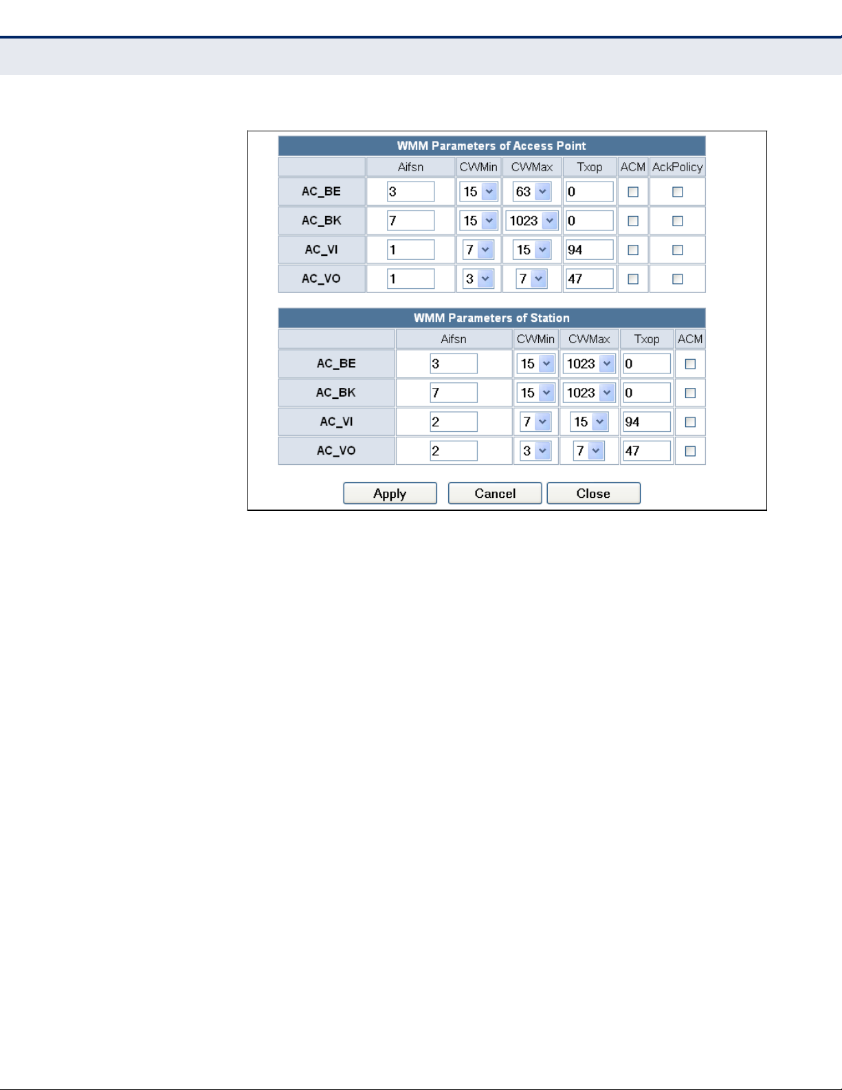
Figure 36:
WMM Configuration
The following items are displayed in the WMM Configuration window:
◆
AIFSN (Arbitration Inter-Frame Space) — The minimum amount of
wait time before the next data transmission attempt. Specify the AIFS
value in the range 0-15 microseconds.
◆
CWMin (Minimum Contention Window) — The initial upper limit of the
random backoff wait time before wireless medium access can be
attempted. The initial wait time is a random value between zero and
the CWMin value. Specify the CWMin value in the range 0-15
microseconds. Note that the CWMin value must be equal or less than
the CWMax value.
◆
CWMax (Maximum Contention Window) — The maximum upper limit
of the random backoff wait time before wireless medium access can be
attempted. The contention window is doubled after each detected
collision up to the CWMax value. Specify the CWMax value in the range
0-15 microseconds. Note that the CWMax value must be greater or
equal to the CWMin value.
◆
Txop (Transmit Opportunity Limit) — The maximum time an AC
transmit queue has access to the wireless medium. When an AC queue
is granted a transmit opportunity, it can transmit data for a time up to
the TxOpLimit. This data bursting greatly improves the efficiency for
high data-rate traffic. Specify a value in the range 0-65535
microseconds.
– 71 –
C
HAPTER
7 | Wireless Configuration
Advanced Settings
Page 72

◆
ACM — The admission control mode for the access category. When
enabled, clients are blocked from using the access category.
(Default: Disabled)
◆
AckPolicy — By default, all wireless data transmissions require the
sender to wait for an acknowledgement from the receiver. WMM allows
the acknowledgement wait time to be turned off for each Access
Category (AC) 0-3. Although this increases data throughput, it can also
result in a high number of errors when traffic levels are heavy.
(Default: Acknowledge)
MULTICAST-TO-
UNICAST CONVERTER
The Multicast-to-Unicast Converter section on the Wireless Settings
Advanced page allows you to enable multicast traffic conversion.
Converting multicast traffic to unicast before sending to wireless clients
allows a longer DTIM (Data Beacon Rate) interval to be set. A longer DTIM
interval prevents clients in power-save mode having to activate their radios
to receive the multicast data, which saves battery life.
Figure 37: Multicast-to-Unicast Converter
The following items are displayed in this section on this page:
◆
Multicast-to-Unicast — Enables multicast traffic streams to be
converted to unicast traffic before delivery to wireless clients.
(Default: Disabled)
–
72 –
C
HAPTER
7 | Wireless Configuration
Advanced Settings
Page 73
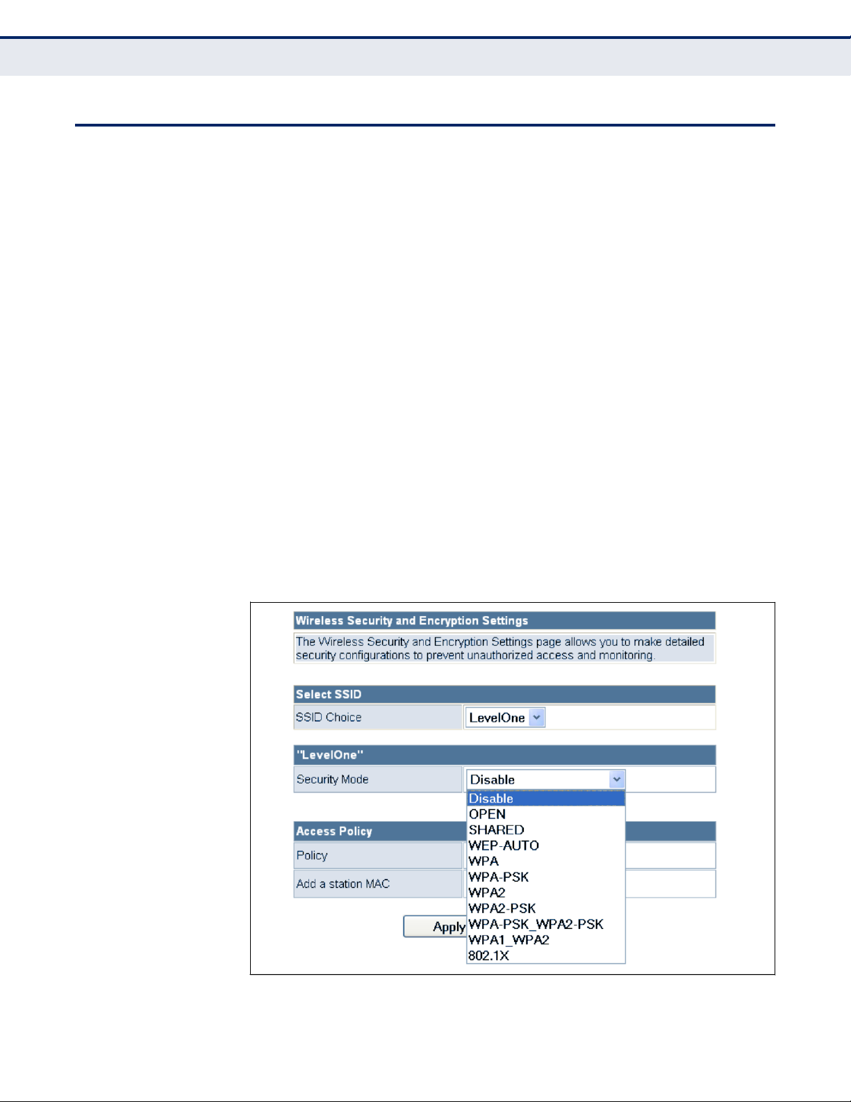
WLAN
S
ECURITY
The Wireless Router‘s wireless interface is configured by default as an
―open system,‖ which broadcasts a beacon signal including the configured
SSID. Wireless clients with a configured SSID of ―ANY‖ can read the SSID
from the beacon, and automatically set their SSID to allow immediate
connection to the wireless network.
To implement wireless network security, you have to employ one or both of
the following functions:
◆
Authentication — It must be verified that clients attempting to
connect to the network are authorized users.
◆
Traffic Encryption — Data passing between the unit and clients must
be protected from interception and eavesdropping.
The Wireless Router supports supports ten different security mechanisms
that provide various levels of authentication and encryption depending on
the requirements of the network.
The Wireless Router supports two SSID interfaces. Each SSID interface
functions as a separate access point, and can be configured with its own
security settings.
Click on ―Wireless Settings,‖ followed by ―Basic‖.
Figure 38:
Security Mode Options
– 73 –
C
HAPTER
7 | Wireless Configuration
WLAN Security
Page 74

The supported security mechanisms and their configuration parameters are
described in the following sections:
◆
OPEN, SHARED, WEP-AUTO — See ―Wired Equivalent Privacy (WEP)‖
on page 74
◆
WPA-PSK, WPA2-PSK, WPA-PSK_WPA2-PSK — See ―WPA Pre-
Shared Key‖ on page 75
◆
WPA, WPA2, WPA1_WPA2 — See ―WPA Enterprise Mode‖ on
page 76
◆
802.1X — See ―IEEE 802.1X and RADIUS‖ on page 78
WIRED EQUIVALENT
PRIVACY (WEP)
WEP provides a basic level of security, preventing unauthorized access to
the network, and encrypting data transmitted between wireless clients and
an access point. WEP uses static shared keys (fixed-length hexadecimal or
alphanumeric strings) that are manually distributed to all clients that want
to use the network.
When you select to use WEP, be sure to define at least one static WEP key
for user authentication or data encryption. Also, be sure that the WEP
shared keys are the same for each client in the wireless network.
Figure 39: Security Mode - WEP
The following items are displayed in this section on this page:
Security Mode — Configures the WEP security mode used by clients.
When using WEP, be sure to define at least one static WEP key for the
Wireless Router and all its clients. (Default: Disable)
◆
OPEN — Open-system authentication accepts any client attempting to
connect the Wireless Router without verifying its identity. In this mode
the default data encryption type is ―WEP.‖
◆
SHARED — The shared-key security uses a WEP key to authenticate
clients connecting to the network and for data encryption.
– 74 –
C
HAPTER
7 | Wireless Configuration
WLAN Security
Page 75

◆
WEP-AUTO — Allows wireless clients to connect to the network using
Open-WEP (uses WEP for encryption only) or Shared-WEP (uses WEP
for authentication and encryption).
◆
Encrypt Type — Selects WEP for data encryption (OPEN mode only).
◆
Default Key — Selects the WEP key number to use for authentication
or data encryption. If wireless clients have all four WEP keys configured
to the same values, you can change the encryption key to any of the
settings without having to update the client keys. (Default: 1;
Range: 1~4)
◆
WEP Keys 1 ~ 4 — Sets WEP key values. The user must first select
ASCII or hexadecimal keys. Each WEP key has an index number. Enter
key values that match the key type and length settings. Enter 5
alphanumeric characters or 10 hexadecimal digits for 64-bit keys, or
enter 13 alphanumeric characters or 26 hexadecimal digits for 128-bit
keys. (Default: Hex, no preset value)
WPA PRE-SHARED
KEY
Wi-Fi Protected Access (WPA) was introduced as an interim solution for the
vulnerability of WEP pending the adoption of a more robust wireless
security standard. WPA2 includes the complete wireless security standard,
but also offers backward compatibility with WPA. Both WPA and WPA2
provide an ―enterprise‖ and ―personal‖ mode of operation.
For small home or office networks, WPA and WPA2 provide a simple
―personal‖ operating mode that uses just a pre-shared key for network
access. The WPA Pre-Shared Key (WPA-PSK) mode uses a common
password phrase for user authentication that is manually entered on the
access point and all wireless clients. Data encryption keys are
automatically generated by the access point and distributed to all clients
connected to the network.
Figure 40: Security Mode - WPA-PSK
The following items are displayed in this section on this page:
Security Mode — Configures the WPA-PSK and WPA2-PSK security modes
used by clients. When using WPA-PSK or WPA2-PSK, be sure to define the
shared key for the Wireless Router and all its clients. (Default: Disable)
◆
WPA-PSK — Clients using WPA with a Pre-shared Key are accepted for
authentication. The default data encryption type for WPA is TKIP.
– 75 –
C
HAPTER
7 | Wireless Configuration
WLAN Security
Page 76

◆
WPA2-PSK — Clients using WPA2 with a Pre-shared Key are accepted
for authentication. The default data encryption type for WPA is AES.
◆
WPA-PSK_WPA2-PSK — Clients using WPA or WPA2 with a Pre-
shared Key are accepted for authentication. The default data encryption
type is TKIP/AES.
◆
WPA Algorithms — Selects the data encryption type to use. (Default
is determined by the Security Mode selected.)
TKIP — Uses Temporal Key Integrity Protocol (TKIP) keys for
encryption. WPA specifies TKIP as the data encryption method to
replace WEP. TKIP avoids the problems of WEP static keys by
dynamically changing data encryption keys.
■
AES — Uses Advanced Encryption Standard (AES) keys for
encryption. WPA2 uses AES Counter-Mode encryption with Cipher
Block Chaining Message Authentication Code (CBC-MAC) for
message integrity. The AES Counter-Mode/CBCMAC Protocol (AESCCMP) provides extremely robust data confidentiality using a 128bit key. Use of AES-CCMP encryption is specified as a standard
requirement for WPA2. Before implementing WPA2 in the network,
be sure client devices are upgraded to WPA2-compliant hardware.
■
TKIP/AES — Uses either TKIP or AES keys for encryption. WPA and
WPA2 mixed modes allow both WPA and WPA2 clients to associate
to a common SSID. In mixed mode, the unicast encryption type
(TKIP or AES) is negotiated for each client.
■
◆
Pass Phrase — The WPA Preshared Key can be input as an ASCII
string (an easy-to-remember form of letters and numbers that can
include spaces) or Hexadecimal format. (Range: 8~63 ASCII
characters, or exactly 64 Hexadecimal digits)
◆
Key Renewal Interval — Sets the time period for automatically
changing data encryption keys and redistributing them to all connected
clients. (Default: 3600 seconds)
WPA ENTERPRISE
MODE
Wi-Fi Protected Access (WPA) was introduced as an interim solution for the
vulnerability of WEP pending the adoption of a more robust wireless
security standard. WPA2 includes the complete wireless security standard,
but also offers backward compatibility with WPA. Both WPA and WPA2
provide an ―enterprise‖ and ―personal‖ mode of operation.
For enterprise deployment, WPA and WPA2 use IEEE 802.1X for user
authentication and require a RADIUS authentication server to be
configured on the wired network. Data encryption keys are automatically
generated and distributed to all clients connected to the network.
– 76 –
C
HAPTER
7 | Wireless Configuration
WLAN Security
Page 77

Figure 41:
Security Mode - WPA
The following items are displayed in this section on this page:
Security Mode — Configures the WPA and WPA2 security modes used by
clients. When using WPA or WPA2, be sure there is a RADIUS server in the
connected wired network, and that the RADIUS settings are configured.
See ―IEEE 802.1X and RADIUS‖ on page 78 for more
information.
(Default:
Disable)
◆
WPA — Clients using WPA with an 802.1X authentication method are
accepted for authentication. The default data encryption type for WPA
is TKIP.
◆
WPA2 — Clients using WPA2 with an 802.1X authentication method
are accepted for authentication. The default data encryption type for
WPA is AES.
◆
WPA1_WPA2 — Clients using WPA or WPA2 with an 802.1X
authentication method are accepted for authentication. The default
data encryption type is TKIP/AES.
◆
WPA Algorithms — Selects the data encryption type to use. (Default
is determined by the Security Mode selected.)
TKIP — Uses Temporal Key Integrity Protocol (TKIP) keys for
encryption. WPA specifies TKIP as the data encryption method to
replace WEP. TKIP avoids the problems of WEP static keys by
dynamically changing data encryption keys.
■
AES — Uses Advanced Encryption Standard (AES) keys for
encryption. WPA2 uses AES Counter-Mode encryption with Cipher
Block Chaining Message Authentication Code (CBC-MAC) for
■
– 77 –
C
HAPTER
7 | Wireless Configuration
WLAN Security
Page 78

message integrity. The AES Counter-Mode/CBCMAC Protocol (AESCCMP) provides extremely robust data confidentiality using a 128bit key. Use of AES-CCMP encryption is specified as a standard
requirement for WPA2. Before implementing WPA2 in the network,
be sure client devices are upgraded to WPA2-compliant hardware.
TKIP/AES — Uses either TKIP or AES keys for encryption. WPA and
WPA2 mixed modes allow both WPA and WPA2 clients to associate
to a common SSID. In mixed mode, the unicast encryption type
(TKIP or AES) is negotiated for each client.
■
◆
Key Renewal Interval — Sets the time period for automatically
changing data encryption keys and redistributing them to all connected
clients. (Default: 3600 seconds)
◆
PMK Cache Period — WPA2 provides fast roaming for authenticated
clients by retaining keys and other security information in a cache, so
that if a client roams away from an access point and then returns
reauthentication is not required. This parameter sets the time for
deleting the cached WPA2 Pairwise Master Key (PMK) security
information. (Default: 10 minutes)
◆
Pre-Authentication — When using WPA2, pre-authentication can be
enabled that allows clients to roam to another access point and be
quickly associated without performing full 802.1X authentication.
(Default: Disabled)
IEEE 802.1X AND
RADIUS
IEEE 802.1X is a standard framework for network access control that uses
a central RADIUS server for user authentication. This control feature
prevents unauthorized access to the network by requiring an 802.1X client
application to submit user credentials for authentication. The 802.1X
standard uses the Extensible Authentication Protocol (EAP) to pass user
credentials (either digital certificates, user names and passwords, or other)
from the client to the RADIUS server. Client authentication is then verified
on the RADIUS server before the client can access the network.
Remote Authentication Dial-in User Service (RADIUS) is an authentication
protocol that uses software running on a central server to control access to
RADIUS-aware devices on the network. An
authentication
server contains a
database of user credentials for each user that requires access to the
network.
The WPA and WPA2 enterprise security modes use 802.1X as the method of
user authentication. IEEE 802.1X can also be enabled on its own as a
security mode for user authentication. When 802.1X is used, a RADIUS
server must be configured and be available on the connected wired network.
NOTE: This guide assumes that you have already configured RADIUS
server(s) to support the access point. Configuration of RADIUS server
software is beyond the scope of this guide, refer to the documentation
provided with the RADIUS server software.
– 78 –
C
HAPTER
7 | Wireless Configuration
WLAN Security
Page 79

Figure 42: Security Mode - 802.1X
The following items are displayed in this section on this page:
Security Mode — Configures the 802.1X security mode used by clients.
When using 802.1X, either with WPA/WPA2 or on its own, be sure there is
a configured RADIUS server in the connected wired network.
(Default: Disable)
802.1X WEP: Selects WEP keys for data encryption. When enabled, WEP
encryption keys are automatically generated by the RADIUS server and
distributed to all connected clients. (Default: Disabled)
RADIUS Server — Configures RADIUS server settings.
◆
IP Address — Specifies the IP address of the RADIUS server.
◆
Port — The User Datagram Protocol (UDP) port number used by the
RADIUS server for authentication messages. (Range: 1024-65535;
Default: 1812)
◆
Shared Secret — A shared text string used to encrypt messages
between the access point and the RADIUS server. Be sure that the
same text string is specified on the RADIUS server. Do not use blank
spaces in the string. (Maximum length: 20 characters)
◆
Session Timeout — Number of seconds the access point waits for a
reply from the RADIUS server before resending a request. (Range: 160 seconds; Default: 0)
◆
Idle Timeout — Sets the maximum time (in seconds) of client
inactivity before a session is terminated.
– 79 –
C
HAPTER
7 | Wireless Configuration
WLAN Security
Page 80
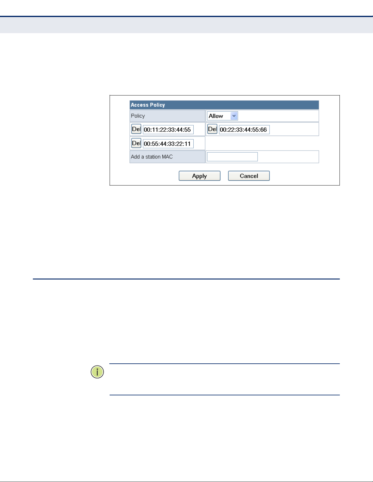
ACCESS POLICY
The Wireless Router provides a MAC address filtering facility. The access
policy can be set to allow or reject specific station MAC addresses. This
feature can be used to connect known wireless devices that may not be
able to support the configured security mode.
Figure 43: Access Policy
The following items are displayed in this section on this page:
◆
Access Policy — The access policy can be set to allow or reject specific
station MAC addresses.
◆
Add a station MAC — Enter the MAC address of the station that you
want to filter. MAC addresses must be entered in the format
xx:xx:xx:xx:xx:xx.
WIRELESS DISTRIBUTION SYSTEM (WDS)
The radio interface can be configured to operate in a mode that allows it to
forward traffic directly to other Wireless Router units. This feature can be
used to extend the range of the wireless network to reach remote clients,
or to link disconnected network segments to an Internet connection.
To set up links between units, you must configure the Wireless Distribution
System (WDS) forwarding table by specifying the wireless MAC address of
all units to which you want to forward traffic.
NOTE: All units in a WDS wireless network must be configured with the
same SSID and use the same radio channel. Also each WDS link must be
configured with the same encryption key on both units in the link.
Up to four WDS links can be specified for each unit in the WDS network.
The following figures illustrate an example WDS network. Figure 44 shows
the manual set up of MAC addresses for units in the WDS network.
Figure 45 shows the basic configuration required on each unit in the WDS
network.
– 80 –
C
HAPTER
7 | Wireless Configuration
Wireless Distribution System (WDS)
Page 81

Figure 44: Manual WDS MAC Address Configuration
Internet
Service
Provider
MAC: 00-22-2D-62-EA-11
WDS MAC List:
00-22-2D-62-EA-22
00-22-2D-62-EA-33
00-22-2D-62-EA-44
MAC: 00-22-2D-62-EA-22
WDS MAC List:
Figure 45: WDS Configuration Example
Internet
Service
Provider
Operation Mode:
Router
WDS Mode:
Bridge
DHCP Server:
Enable
LAN IP Address:
192.168.0.1
LAN IP Address:
192.168.0.4
WDS Mode:
Lazy
LAN IP Address:
192.168.0.2
LAN IP Address:
192.168.0.3
A WDS link between two units can be configured in any of the following
Operation Mode combinations:
1.
Both units in a link are configured as Router Mode.
2.
One unit in a link is configured in Router Mode and the other in Bridge
Mode.
3.
Both units in a link are configured as Bridge Mode.
When two or more units in the WDS network are set to Router Mode, be
sure to check these settings:
◆
Be sure each unit is configured with a different LAN IP address.
– 81 –
Operation Mode:
Bridge
DHCP Server:
Disable
LAN IP
Address:
Operation Mode:
Bridge
WDS Mode:
Repeater
DHCP Server:
Disable
LAN IP
Address:
Operation Mode:
Router
WDS Mode:
Lazy
DHCP Server:
Disable
LAN IP
Address:
Cable/DSL
Modem
MAC: 00-22-2D-62-EA-33
00-22-2D-62-EA-11
MAC:
WDS MAC List:
00-22-2D-62-EA-11
Cable/DSL
Modem
C
HAPTER
7 | Wireless Configuration
Wireless Distribution System (WDS)
Page 82
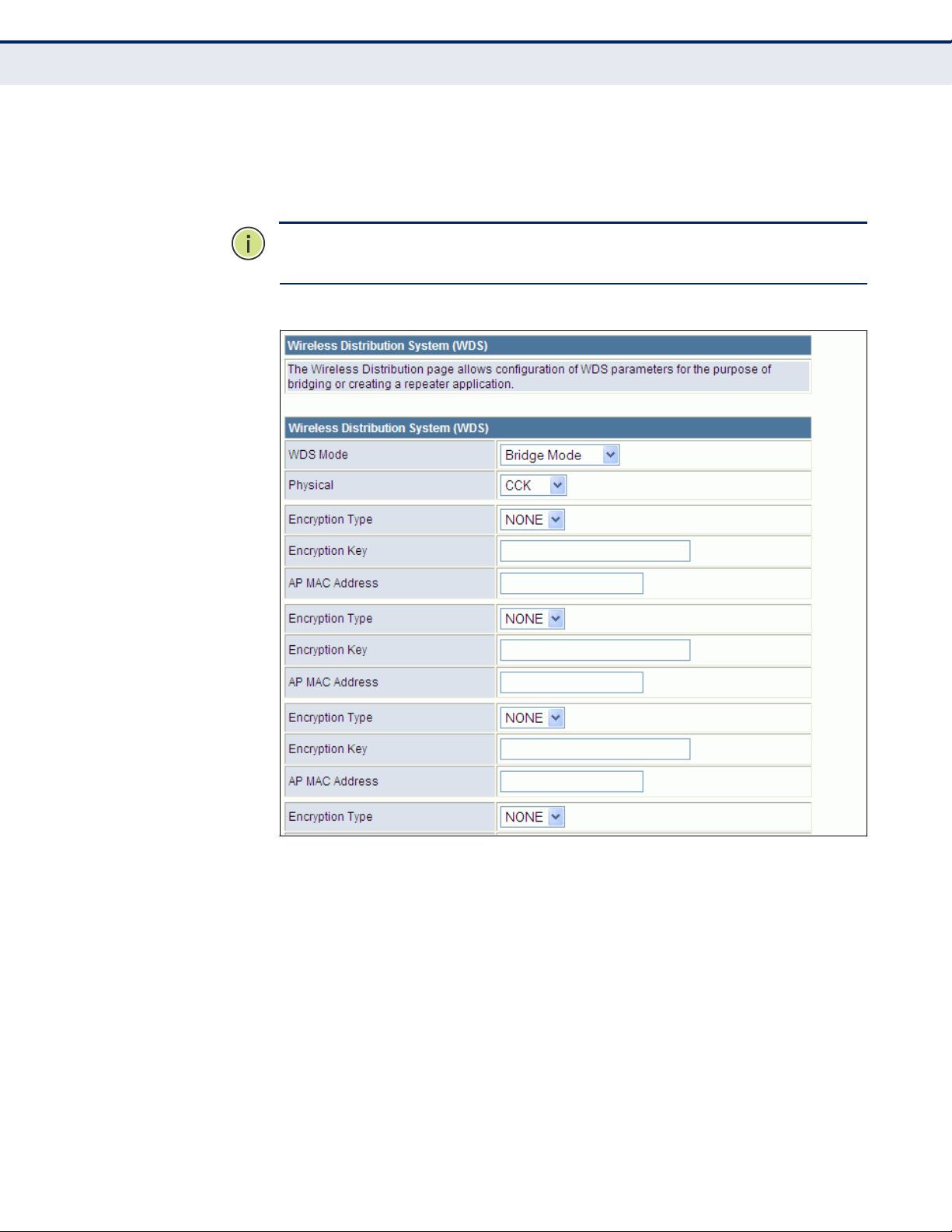
◆
Be sure that only one unit has an Internet access on its WAN port.
◆
Be sure the DHCP server is enabled only on one unit. When one unit is
providing Internet access, enable the DHCP server on that unit.
NOTE: When using WDS Lazy mode in the network, at least one unit must
be set to Bridge or Repeater mode.
Figure 46:
WDS Configuration
The WDS settings configure WDS related parameters. Up to four MAC
addresses can be specified for each unit in the WDS network. WDS links
may either be manually configured (Bridge and Repeater modes) or autodiscovered (Lazy mode).
The following items are displayed on this page:
◆
WDS Mode — Selects the WDS mode of the SSID. (Options: Disable,
Lazy, Bridge, Repeater. Default: Disable)
Disable: WDS is disabled.
■
Lazy: Operates in an automatic mode that detects and learns WDS
peer addresses from received WDS packets, without the need to
■
– 82 –
C
HAPTER
7 | Wireless Configuration
Wireless Distribution System (WDS)
Page 83

configure a WDS MAC list entry. This feature allows the Wireless
Router to associate with other Wireless Routers in the network and
use their WDS MAC list. Lazy mode requires one other Wireless
Router within the wireless network that is configured in Bridge or
Repeater mode, and has a configured MAC address list.
Bridge: Operates as a standard bridge that forwards traffic
between WDS links (links that connect to other units in Repeater or
Lazy mode). The MAC addresses of WDS peers must be configured
on the Wireless Router.
■
Repeater: Operates as a wireless repeater, extending the range for
remote wireless clients and connecting them to an AP connected to
the wired network. The MAC addresses of WDS peers must be
configured on the Wireless Router.
■
◆
Physical — The radio media coding used on all WDS links. CCK
corresponds to 11b, OFDM corresponds to 11g, and HTMIX corresponds
to 11n.
◆
Encryption Type — The data encryption used on the WDS link. Be
sure that both ends of a WDS link are configured with the same
encryption type and key. (Options: None, WEP, TKIP, AES.
Default: None)
◆
Encryption Key — The encryption key for the WDS link. The key type
and length varies depending on the encryption type selected. For WEP,
enter 5 alphanumeric characters or 10 hexadecimal digits for 64-bit
keys, or 13 alphanumeric characters or 26 hexadecimal digits for 128bit keys. For TKIP or AES, enter a password key phrase of between 8 to
63 ASCII characters, which can include spaces, or specify exactly 64
hexadecimal digits.
◆
AP MAC Address — The MAC address of the other Wireless Router in
the WDS link.
WI-FI PROTECTED SETUP (WPS)
Wi-Fi Protected Setup (WPS) is designed to ease installation and activation
of security features in wireless networks. WPS has two basic modes of
operation, Push-button Configuration (PBC) and Personal Identification
Number (PIN). The WPS PIN setup is optional to the PBC setup and
provides more security. The WPS button on the Wireless Router can be
pressed at any time to allow a single device to easily join the network.
The WPS Settings page includes configuration options for setting WPS
device PIN codes and activating the virtual WPS button.
Click on ―Wireless Settings,‖ followed by ―WPS‖.
– 83 –
C
HAPTER
7 | Wireless Configuration
Wi-Fi Protected Setup (WPS)
Page 84
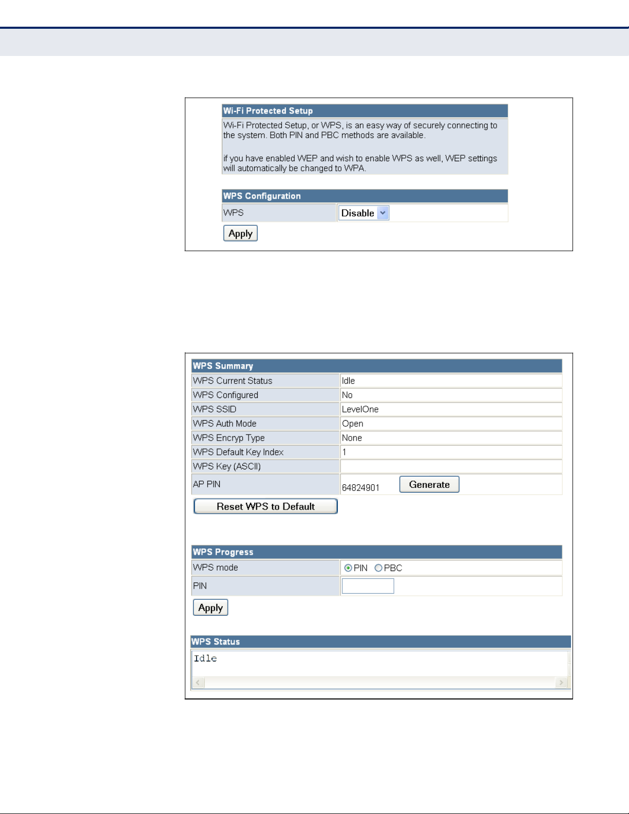
Figure 47: Enabling WPS
The following items are displayed on this page:
◆
WPS — Enables WPS, locks security settings, and refreshes WPS
configuration information. (Default: Disabled)
Figure 48:
WPS Configuration
– 84 –
C
HAPTER
7 | Wireless Configuration
Wi-Fi Protected Setup (WPS)
Page 85

The following items are displayed on this page:
WPS Summary — Provides detailed WPS statistical information.
◆
WPS Current Status — Displays if there is currently any WPS traffic
connecting to the Wireless Router. (Options: Start WSC Process; Idle)
◆
WPS Configured — States if WPS for wireless clients has been
configured for this device.
◆
WPS SSID — The service set identifier for the unit.
◆
WPS Auth Mode — The method of authentication used.
◆
WPS Encryp Type — The encryption type used for the unit.
◆
WPS Default Key Index — Displays the WEP default key (1~4).
◆
WPS Key (ASCII) — Displays the WPS security key (ASCII) which can
be used to ensure the security of the wireless network.
◆
AP PIN — Displays the PIN Code for the Wireless Router. The default is
exclusive for each unit. (Default: 64824901)
◆
Reset WPS to Default — Resets the WPS settings to factory default
values.
WPS Config — Configures WPS settings for the Wireless Router.
◆
WPS Mode — Selects between methods of broadcasting the WPS
beacon to network clients wanting to join the network:
PIN: The Wireless Router, along with other WPS devices, such as
notebook PCs, cameras, or phones, all come with their own eightdigit PIN code. When one device, the WPS enrollee, sends a PIN
code to the Wireless Router, it becomes the WPS registrar. After
configuring PIN-Code information you must press ―Apply‖ to send
the beacon, after which you have up to two minutes to activate WPS
on devices that need to join the network.
■
PBC: This has the same effect as pressing the physical WPS button
that is located on the front of the Wireless Router. After checking
this option and clicking ―Apply‖ you have up to two minutes to
activate WPS on devices that need to join the network.
■
– 85 –
C
HAPTER
7 | Wireless Configuration
Wi-Fi Protected Setup (WPS)
Page 86

STATION
L
IST
Displays the station information which associated to this Wireless Router.
Figure 49:
Station List
–
86 –
C
HAPTER
7 | Wireless Configuration
Station List
Page 87

The Wireless Router provides extensive firewall protection by restricting
connection parameters to limit the risk of intrusion and defending against a
wide array of common hacker attacks.
Firewall Configuration contains the following sections:
◆
―MAC/IP/Port Filtering‖ on page 87
◆
―Virtual Server Settings (Port Forwarding)‖ on page 90
◆
―DMZ‖ on page 91
◆
―System Security‖ on page 92
◆
―Content Filtering‖ on page 93
MAC/IP/PORT
F
ILTERING
MAC/IP/Port filtering restricts connection parameters to limit the risk of
intrusion and defends against a wide array of common hacker attacks.
MAC/IP/Port filtering allows the unit to permit, deny or proxy traffic
through its MAC addresses, IP addresses and ports.
The Wireless Router allows you define a sequential list of permit or deny
filtering rules (up to 32). This device tests ingress packets against the filter
rules one by one. A packet will be accepted as soon as it matches a permit
rule, or dropped as soon as it matches a deny rule. If no rules match, the
packet is either accepted or dropped depending on the default policy
setting.
– 87 –
8
FIREWALL CONFIGURATION
Page 88
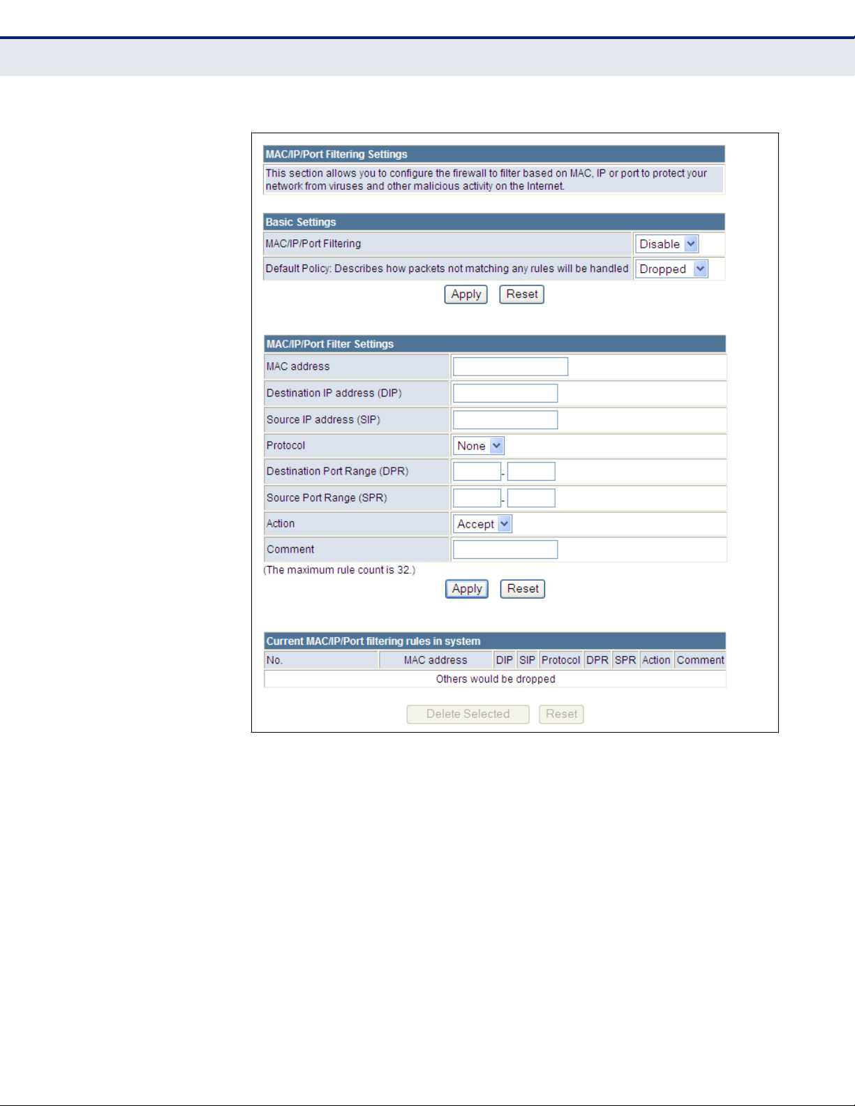
Figure 50:
MAC/IP/Port Filtering
The following items are displayed on this page:
◆
MAC/IP/Port Filtering — Enables or disables MAC/IP/Port Filtering.
(Default: Disable)
◆
Default Policy — When MAC/IP/Port Filtering is enabled, the default
policy will be enabled. If you set the default policy to ―Dropped‖, all
incoming packets that don‘t match the rules will be dropped. If the
policy is set to "Accepted," all incoming packets that don't match the
rules are accepted. (Default: Dropped)
◆
MAC Address — Specifies the MAC address to block or allow traffic
from.
– 88 –
C
HAPTER
8 | Firewall Configuration
MAC/IP/Port Filtering
Page 89

◆
Destination IP Address — Specifies the destination IP address to
block or allow traffic from.
◆
Source IP Address — Specifies the source IP address to block or allow
traffic from.
◆
Protocol — Specifies the destination port type, TCP, UDP or ICMP.
(Default: None).
◆
Destination Port Range — Specifies the range of destination port to
block traffic from the specified LAN IP address from reaching.
◆
Source Port Range — Specifies the range of source port to block
traffic from the specified LAN IP address from reaching.
◆
Action — Specifies if traffic should be accepted or dropped. (Default:
Accept)
◆
Comment — Enter a useful comment to help identify the filtering rules.
CURRENT FILTER
RULES
The Current Filter Table displays the configured IP addresses and ports that
are permitted or denied access to and from the Wireless Router.
◆
Select — Selects a table entry.
◆
MAC Address — Displays a MAC address to filter.
◆
Destination IP Address — Displays the destination IP address.
◆
Source IP Address — Displays the source IP address.
◆
Protocol — Displays the destination port type.
◆
Destination Port Range — Displays the destination port range.
◆
Source Port Range — Displays the source port range.
◆
Action — Displays if the specified traffic is accepted or dropped.
◆
Comment — Displays a useful comment to identify the routing rules.
– 89 –
C
HAPTER
8 | Firewall Configuration
MAC/IP/Port Filtering
Page 90

VIRTUAL SERVER SETTINGS (PORT
F
ORWARDING
)
Virtual Server (sometimes referred to as Port Forwarding) is the act of
forwarding a network port from one network node to another. This
technique can allow an external user to reach a port on a private IP
address (inside a LAN) from the outside through a NAT-enabled router.
(Maximum 32 entries are allowed.)
Figure 51:
Virtual Server
The following items are displayed on this page:
◆
Virtual Server Settings — Selects between enabling or disabling port
forwarding the virtual server. (Default: Disable)
◆
IP Address — Specifies the IP address on the local network to allow
external access.
◆
Port Range — Specifies the port range through which traffic is
forwarded.
◆
Protocol — Specifies a protocol to use for port forwarding, either TCP,
UDP or TCP&UDP.
◆
Comment — Enter a useful comment to help identify the forwarded
port service on the network.
– 90 –
C
HAPTER
8 | Firewall Configuration
Virtual Server Settings (Port Forwarding)
Page 91

CURRENT VIRTUAL
SERVERS IN SYSTEM
The Current Port Forwarding Table displays the entries that are allowed to
forward packets through the Wireless Router‘s firewall.
◆
No. — The table entry number.
◆
IP Address — Displays an IP address on the local network to allow
external access to.
◆
Port Mapping — Displays the port the server is mapped.
◆
Protocol — Displays the protocol used for forwarding of this port.
◆
Comment — Displays a useful comment to identify the nature of the
port to be forwarded.
DMZ
Enables a specified host PC on the local network to access the Internet
without any firewall protection. Some Internet applications, such as
interactive games or video conferencing, may not function properly behind
the Wireless Router's firewall. By specifying a Demilitarized Zone (DMZ)
host, the PC's TCP ports are completely exposed to the Internet, allowing
open two-way communication. The host PC should be assigned a static IP
address (which is mapped to its MAC address) and this must be configured
as the DMZ IP address.
Figure 52: DMZ
The following items are displayed on this page:
◆
DMZ Settings — Sets the DMZ status. (Default: Disable)
◆
DMZ IP Address — Specifies an IP address on the local network
allowed unblocked access to the WAN.
– 91 –
C
HAPTER
8 | Firewall Configuration
DMZ
Page 92

SYSTEM
S
ECURITY
The Wireless Router includes the facility to manage it from a remote
location. The unit can also be sent a ping message from a remote location.
Figure 53:
System Security
The following items are displayed on this page:
◆
Remote Management — Denies or allows management access to the
Wireless Router through the WAN interface. When connecting with the
web interface from the WAN port, be sure to specify TCP port 8080 in
the URL; for example,
―http://200.180.1.19:8080,‖
where
―200.180.1.19‖ is the WAN IP address. (Default: Deny)
◆
Ping from WAN Filter — When enabled, the Wireless Router does not
respond to ping packets received on the WAN port. (Default: Disable)
◆
Stateful Packet Inspection (SPI) — The Stateful Packet Inspection
(SPI) firewall protects your network and computers against attacks and
intrusions. A stateful packet firewall looks at packet contents to check if
the traffic may involve some type of security risk. (Default: Enable)
– 92 –
C
HAPTER
8 | Firewall Configuration
System Security
Page 93

CONTENT
F
ILTERING
The Wireless Router provides a variety of options for blocking Internet
access based on content, URL and host name.
Figure 54:
Content Filtering
The following items are displayed on this page:
Web URL Filter Settings — By filtering inbound Uniform Resource
Locators (URLs) the risk of compromising the network can be reduced.
URLs are commonly used to point to websites. By specifying a URL or a
keyword contained in a URL traffic from that site may be blocked.
◆
Current URL Filters — Displays current URL filter.
◆
Add a URL Filter — Adds a URL filter to the settings. For example,
myhost.example.com.
Web Host Filter Settings — The Wireless Router allows Internet content
access to be restricted based on web address keywords and web domains.
A domain name is the name of a particular web site. For example, for the
address
www.FUNGAMES.com,
the domain name is FUNGAMES.com. Enter
the Keyword then click ―Add‖.
– 93 –
C
HAPTER
8 | Firewall Configuration
Content Filtering
Page 94

◆
Current Host Filters — Displays current Host filter.
◆
Add a Host Filter — Enters the keyword for a host filtering.
– 94 –
C
HAPTER
8 | Firewall Configuration
Content Filtering
Page 95

The Wireless Router‘s Administration Settings menu provides the same
configuration options in both Router and Bridge Mode. These settings allow
you to configure a management access password, set the system time,
upgrade the system software, display the system status and statistics.
Administration Settings contains the following sections:
◆
―System Management‖ on page 96
◆
―Time Zone Settings‖ on page 97
◆
―DDNS Settings‖ on page 98
◆
―Firmware Upgrade‖ on page 99
◆
―Configuration Settings‖ on page 100
◆
―System Status‖ on page 101
◆
―Statistics‖ on page 103
◆
―System Log‖ on page 104
– 95 –
9
ADMINISTRATION SETTINGS
Page 96
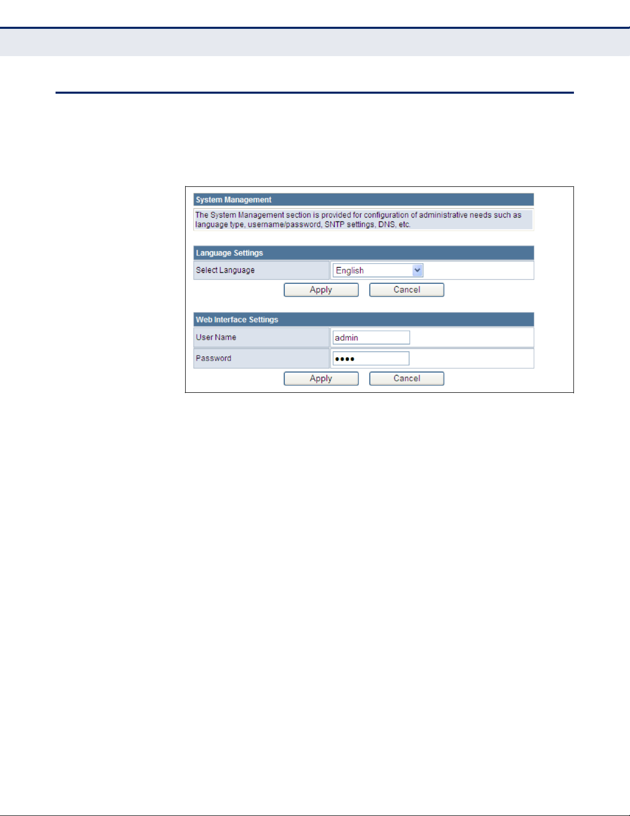
SYSTEM
M
ANAGEMENT
The System Management commands allow you to change the language
settings displayed in the interface, and change the user name and
password.
Figure 55: System Management
The following items are displayed in the first two sections on this page:
◆
Language Settings — You can change the language displayed in web
interface. Select the language of your choice from the drop-down list,
then click ―Apply‖. (Options: English, Traditional Chinese, or Simple
Chinese. Default: English)
◆
Web Interface Settings — To protect access to the management
interface, you need to configure a new administrator‘s user name and
password as soon as possible. If a new user name and password are
not configured, then anyone having access to the Wireless Router may
be able to compromise the unit's security by entering the default
values.
User Name — The name of the user. The default name for access
to the unit is ―admin‖. (Length: 3-16 characters, case sensitive)
■
Password — The password for management access. The default
password preset for access to the unit is ―password‖ (Length: 3-16
characters, case sensitive)
■
– 96 –
C
HAPTER
9 | Administration Settings
System Management
Page 97
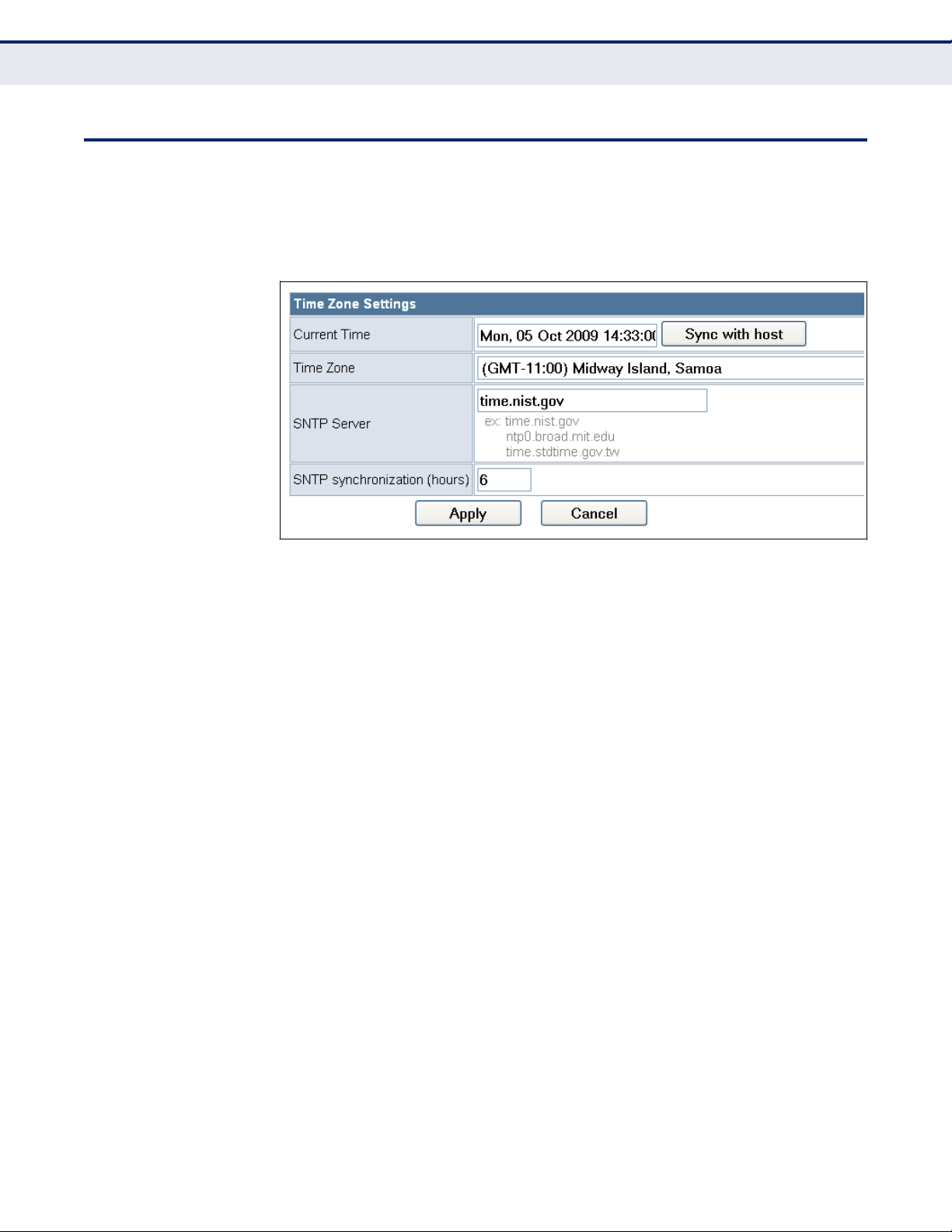
TIME ZONE
S
ETTINGS
The System Management page allows you to manually configure time
settings or enable the use of a Simple Network Time Protocol (SNTP) or
NTP server.
Figure 56: Time Zone Settings
The following items are displayed in this section on this page:
◆
Current Time — Displays the current system time on the unit.
◆
Sync with host — Updates the unit's time from the web management
PC's system time.
◆
Time Zone — Specifies the time zone in relation to Greenwich Mean
Time (GMT).
◆
SNTP Server — The IP address or URL of the NTP server to be used.
◆
SNTP synchronization — Sets the SNTP sycnronization in hours.
– 97 –
C
HAPTER
9 | Administration Settings
Time Zone Settings
Page 98

DDNS
S
ETTINGS
Dynamic DNS (DDNS) provides users on the Internet with a method to tie
a specific domain name to the unit‘s dynamically assigned IP address.
DDNS allows your domain name to follow your IP address automatically by
changing your DNS records when your IP address changes.
The Wireless Router provides access to three DDNS service providers,
DynDns.org, Non-IP.com and ZoneEdit.com. To set up an DDNS account,
visit the websites of these service providers at www.dyndns.org, www.nonip.com, or www.zoneedit.com.
Figure 57: DDNS Settings (Router Mode)
The following items are displayed in this section on this page:
◆
Dynamic DNS Provider — Specifies the DDNS service provider,
DynDns.org, Freedns.afraid.org, ZoneEdit.com or Non-IP.com.
(Default: none)
◆
User Name — Specifies your user name for the DDNS service.
◆
Password — Specifies your password for the DDNS service.
◆
HostName — Specifies the URL of the DDNS service.
– 98 –
C
HAPTER
9 | Administration Settings
DDNS Settings
Page 99
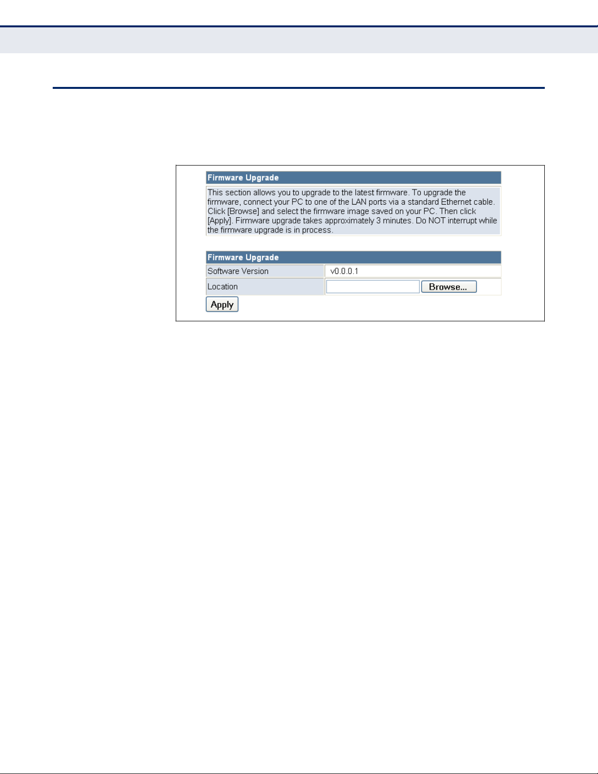
FIRMWARE
U
PGRADE
You can update the Wireless Router firmware by using the Firmware
Update facility.
Figure 58: Firmware Upgrade
The following items are displayed on this page:
◆
Firmware Upgrade — Allows you to upload new firmware manually by
specifying a file path. Make sure the firmware you want to use is on the
local computer by clicking Browse to search for the firmware to be used
for the update.
Software Version — The current version number of the firmware.
■
Browse — Opens a directory on the local hard drive for specifying
the path of the file to upload.
■
Apply — Starts the upload procedure.
■
– 99 –
C
HAPTER
9 | Administration Settings
Firmware Upgrade
Page 100

CONFIGURATION
S
ETTINGS
The Configuration Setting page allows you to save the Wireless Router‘s
current configuration or restore a previously saved configuration back to
the device.
Figure 59:
Configuration Settings
The following items are displayed on this page:
◆
Export Settings — Saves the current configuration to a file locally.
◆
Import Settings — Allows the user to load previously saved
configuration files from a local source.
◆
Load Factory Defaults — Restores the factory defaults.
– 100 –
C
HAPTER
9 | Administration Settings
Configuration Settings
 Loading...