

Page 1
S400
Safety switch
EN 2014/07 - 607920
We reserve the right to
make technical changes
SAFE IMPLEMENTATION AND OPERATION
Original operating instructions
Page 2

© 2014
Leuze electronic GmbH + Co. KG
In der Braike 1
D-73277 Owen / Germany
Phone: +49 7021 573-0
Fax: +49 7021 573-199
http://www.leuze.com
Leuze electronic S400 2
Page 3

1 About this document. . . . . . . . . . . . . . . . . . . . . . . . . . . . . . . . . . . . . . . . . . . . . . . . . . . . 4
1.1 Other applicable documents . . . . . . . . . . . . . . . . . . . . . . . . . . . . . . . . . . . . . . . . . . . . . . . . . . . . . . . 4
1.2 Used symbols and signal words . . . . . . . . . . . . . . . . . . . . . . . . . . . . . . . . . . . . . . . . . . . . . . . . . . . . 4
2 Safety . . . . . . . . . . . . . . . . . . . . . . . . . . . . . . . . . . . . . . . . . . . . . . . . . . . . . . . . . . . . . . . 5
2.1 Approved purpose and foreseeable improper operation . . . . . . . . . . . . . . . . . . . . . . . . . . . . . . . . . . 5
2.1.1 Proper use . . . . . . . . . . . . . . . . . . . . . . . . . . . . . . . . . . . . . . . . . . . . . . . . . . . . . . . . . . . . . . . . . . . . . 5
2.1.2 Foreseeable misuse . . . . . . . . . . . . . . . . . . . . . . . . . . . . . . . . . . . . . . . . . . . . . . . . . . . . . . . . . . . . . 6
2.2 Competent personnel . . . . . . . . . . . . . . . . . . . . . . . . . . . . . . . . . . . . . . . . . . . . . . . . . . . . . . . . . . . . 6
2.3 Responsibility for safety. . . . . . . . . . . . . . . . . . . . . . . . . . . . . . . . . . . . . . . . . . . . . . . . . . . . . . . . . . . 6
2.4 Disclaimer . . . . . . . . . . . . . . . . . . . . . . . . . . . . . . . . . . . . . . . . . . . . . . . . . . . . . . . . . . . . . . . . . . . . . 7
3 Device description . . . . . . . . . . . . . . . . . . . . . . . . . . . . . . . . . . . . . . . . . . . . . . . . . . . . . 8
3.1 Device overview. . . . . . . . . . . . . . . . . . . . . . . . . . . . . . . . . . . . . . . . . . . . . . . . . . . . . . . . . . . . . . . . . 8
4 Functions . . . . . . . . . . . . . . . . . . . . . . . . . . . . . . . . . . . . . . . . . . . . . . . . . . . . . . . . . . . 10
4.1 Special functions and performance characteristics of the S420-OSx series . . . . . . . . . . . . . . . . . . 10
4.2 Display elements . . . . . . . . . . . . . . . . . . . . . . . . . . . . . . . . . . . . . . . . . . . . . . . . . . . . . . . . . . . . . . . 10
5 Applications . . . . . . . . . . . . . . . . . . . . . . . . . . . . . . . . . . . . . . . . . . . . . . . . . . . . . . . . . 12
6 Mounting. . . . . . . . . . . . . . . . . . . . . . . . . . . . . . . . . . . . . . . . . . . . . . . . . . . . . . . . . . . . 13
6.1 Mounting the safety hinge switch. . . . . . . . . . . . . . . . . . . . . . . . . . . . . . . . . . . . . . . . . . . . . . . . . . . 13
7 Electrical connection . . . . . . . . . . . . . . . . . . . . . . . . . . . . . . . . . . . . . . . . . . . . . . . . . . 20
7.1 Connecting the contact block. . . . . . . . . . . . . . . . . . . . . . . . . . . . . . . . . . . . . . . . . . . . . . . . . . . . . . 20
8 Starting up the device. . . . . . . . . . . . . . . . . . . . . . . . . . . . . . . . . . . . . . . . . . . . . . . . . . 24
9 Testing . . . . . . . . . . . . . . . . . . . . . . . . . . . . . . . . . . . . . . . . . . . . . . . . . . . . . . . . . . . . . 25
9.1 To be performed prior to the initial start-up by competent personnel . . . . . . . . . . . . . . . . . . . . . . . 25
9.2 To be performed periodically by competent personnel . . . . . . . . . . . . . . . . . . . . . . . . . . . . . . . . . . 25
9.3 To be performed daily by the operating personnel . . . . . . . . . . . . . . . . . . . . . . . . . . . . . . . . . . . . . 25
10 Cleaning . . . . . . . . . . . . . . . . . . . . . . . . . . . . . . . . . . . . . . . . . . . . . . . . . . . . . . . . . . . . 26
11 Disposing . . . . . . . . . . . . . . . . . . . . . . . . . . . . . . . . . . . . . . . . . . . . . . . . . . . . . . . . . . . 27
12 Service and support . . . . . . . . . . . . . . . . . . . . . . . . . . . . . . . . . . . . . . . . . . . . . . . . . . . 28
13 Technical data . . . . . . . . . . . . . . . . . . . . . . . . . . . . . . . . . . . . . . . . . . . . . . . . . . . . . . . 29
13.1 Dimensions . . . . . . . . . . . . . . . . . . . . . . . . . . . . . . . . . . . . . . . . . . . . . . . . . . . . . . . . . . . . . . . . . . . 32
14 Ordering information and accessories . . . . . . . . . . . . . . . . . . . . . . . . . . . . . . . . . . . . . 35
14.1 Accessories . . . . . . . . . . . . . . . . . . . . . . . . . . . . . . . . . . . . . . . . . . . . . . . . . . . . . . . . . . . . . . . . . . . 35
15 EC Declaration of Conformity. . . . . . . . . . . . . . . . . . . . . . . . . . . . . . . . . . . . . . . . . . . . 38
Leuze electronic S400 3
Page 4
1 About this document
1.1 Other applicable documents
The information on the S400, S410 and S420 safety hinge switches is divided into two documents. Docu-
ment “S400 Application information” contains only the most important safety notices.
For the safe implementation, testing and operation, download document “S400 Safe implementation
and operation” from http://www.leuze.com/s400/ or request it from service.protect@leuze.de or
tel. +49 8141 5350-111.
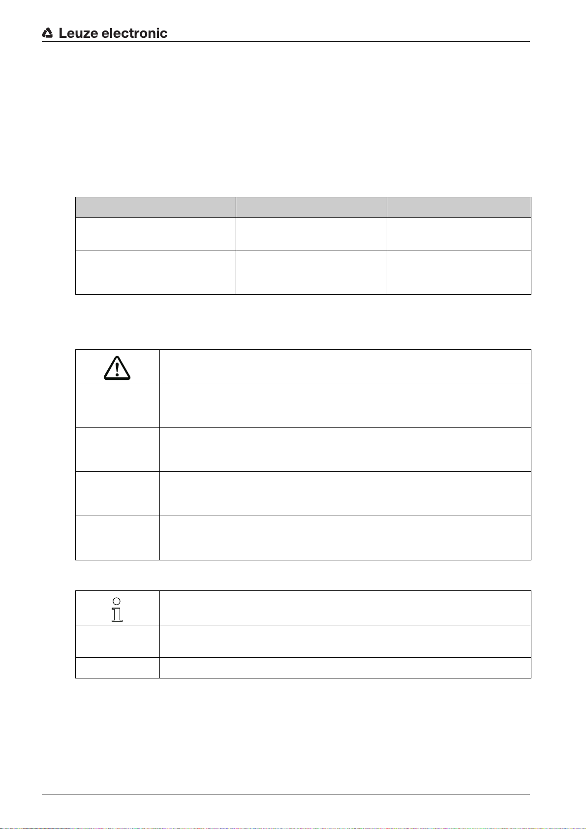
Table 1.1: Documents on the safety hinge switch
Purpose and target group Title Source
About this document
Detailed information for all users S400 Safe implementation and
Basic information for technicians
and operating company
1.2 Used symbols and signal words
Table 1.2: Warning symbols and signal words
Symbol for dangers
NOTICE Signal word for property damage
Indicates dangers that may result in property damage if the measures for danger
avoidance are not followed.
CAUTION Signal word for minor injury
Indicates dangers that may result in minor injury if the measures for danger avoidance are not followed.
WARNING Signal word for serious injury
Indicates dangers that may result in severe or fatal injury if the measures for danger
avoidance are not followed.
On the Internet, download from:
operation (this document)
S400 Application information Print document part no. 607240
http://www.leuze.com/s400/
included in the delivery contents of the product
DANGER Signal word for life-threatening danger
Indicates dangers that will result in severe or fatal injury if the measures for danger
avoidance are not followed.
Table 1.3: Other symbols
Symbol for tips
Text passages with this symbol provide you with further information.
xxx Placeholder in the product description for all variants
Leuze electronic S400 4
Symbols for action steps
Text passages with this symbol instruct you to perform actions.
Page 5
2 Safety
Before using the safety hinge switch, a risk assessment must be performed according to valid standards
(e.g. EN ISO 12100, EN ISO 13849-1). For mounting, operating and testing, document S400 Sicher imple-
mentieren und betreiben, application information as well as all applicable national and international stan-
dards, regulations, rules and directives must be observed. Observe and print out relevant and supplied
documents and distribute to the affected personnel.
The following standards apply for the risk assessment at the protective device prior to using the safety
hinge switch:
• EN ISO 12100, Safety of machinery, risk assessment
• EN ISO 13849-1, Safety-related parts of control systems
The realizable category of the integration in control circuits according to EN ISO 13849-1 is dependent on
the used contact block and wiring.
In particular, the following national and international legal regulations apply for the start-up, technical
inspections and work with safety hinge switch:
• Machinery directive 2006/42/EC
• Low voltage directive 2006/95/EC
• Use of work equipment directive 2009/104/EC
• Safety regulations
• Accident-prevention regulations and safety rules
• Industrial safety regulation and employment protection act
• Product Safety Act
Safety
For safety-related information you may also contact the local authorities (e.g., industrial inspec-
torate, employer's liability insurance association, labor inspectorate, occupational safety and
health authority).
2.1 Approved purpose and foreseeable improper operation
2.1.1 Proper use
• The safety hinge switch must only be used after it has been selected in accordance with the respectively applicable instructions and relevant standards, rules and regulations regarding labor protection
and safety at work, and after it has been installed on the machine, connected, commissioned, and
checked by a competent and authorized person.
• When selecting the safety hinge switch it must be ensured that its safety-related capability meets or
exceeds the required performance level PL
• It must be in perfect condition and inspected regularly.
• The safety hinge switch may be used in combination with a safety relay or a safety control.
WARNING
A running machine can cause severe injuries!
Make certain that, during all conversions, maintenance work and inspections, the system is securely
shut down and protected against being restarted.
ascertained in the risk assessment.
r
S400, S410 and S420 safety hinge switches must be connected in such a way that a dangerous state can
only be activated while the protective device is closed and so that the dangerous state stops upon opening
of the protective device. It must not be used if the point of operation can be accessed during the lag time
before the dangerous state has ended. If stepping behind the guard is possible, a start/restart interlock is
mandatory.
Connection conditions:
• the dangerous state can only be activated while the protective device is closed
• opening the protective device while the machine is running triggers a stop command and ends the
dangerous state
Leuze electronic S400 5
Page 6
Safety
Furthermore, the S400, S410 or S420 safety hinge switch must not be used under the following conditions:
• rapidly changing ambient temperature (leads to condensation)
• in the event of strong physical shocks
• when ice has formed
• in explosive or easily flammable atmospheres
• in the event of aggressive chemical influences
• the mounting locations are not sufficiently stable
• the safety of multiple persons is dependent on the function of this safety switch (e.g. nuclear power
plants, trains, aircraft, motor vehicles, incinerators, medical devices)
For machines with longer slowdowns, a safety locking device must be used.
Handling the safety hinge switch:
Observe the permissible environmental conditions for storage and operation (see chapter 13 „Technical
data“).
Immediately replace damaged safety hinge switch according to these instructions.
Use cable gland, insulation materials and connecting wires of the appropriate protection rating.
Protect the safety hinge switch from penetrating foreign bodies (e.g. shavings, sand and blasting agent).
Cover before performing painting work.
Immediately clean any contamination from the safety hinge switch that impacts function according to
these instructions.
Do not open the cover on the rear side.
Make no structural changes to the safety hinge switch.
The safety hinge switch must be exchanged after a maximum of 20 years.
2.1.2 Foreseeable misuse
Any use other than that defined under the "approved purpose" or
hinge switch is considered improper use!
E.g. - using without non-detachably mounted actuator
• looping into the safety circuit parts that are not relevant to safety
• using the hinge switch as a limit stop
2.2 Competent personnel
Prerequisites for competent personnel:
• suitable technical training
• knows the rules and regulations for labor protection, safety at work and safety technology and can
assess the safety of the machine
• knows the instructions for the safety hinge switch and the machine and understands them
• was instructed by the responsible individuals on the mounting and operation of the machine and of
the safety hinge switch
2.3 Responsibility for safety
Manufacturer and operating company must ensure that the machine and implemented safety hinge switch
function properly and that all affected persons are adequately informed and trained.
The type and content of all imparted information must not lead to unsafe actions by users.
which goes beyond that use of the safety
Leuze electronic S400 6
Page 7
The manufacturer of the machine is responsible for:
• safe machine construction
• safe implementation of the safety hinge switch
• imparting all relevant information to the operating company
• adhering to all regulations and directives for the safe starting-up of the machine
The operating company is responsible for:
• instructing the operating personnel
• maintaining the safe operation of the machine
• adhering to all regulations and directives for labor protection and safety at work
• regular testing by competent personnel
2.4 Disclaimer
Leuze electronic GmbH + Co. KG is not liable in the following cases:
• Safety hinge switch is not used as intended
• Safety notices are not adhered to
• Testing is not performed by competent and authorized personnel
• Faulty mounting, connection, start-up
• Deficient execution of tests for proper protective function
• Reasonably foreseeable misuse is not taken into account (e.g. manipulation, reaching behind the
safety device)
• Technical data is not observed
Safety
Leuze electronic S400 7
Page 8
3 Device description
1
3
2
1
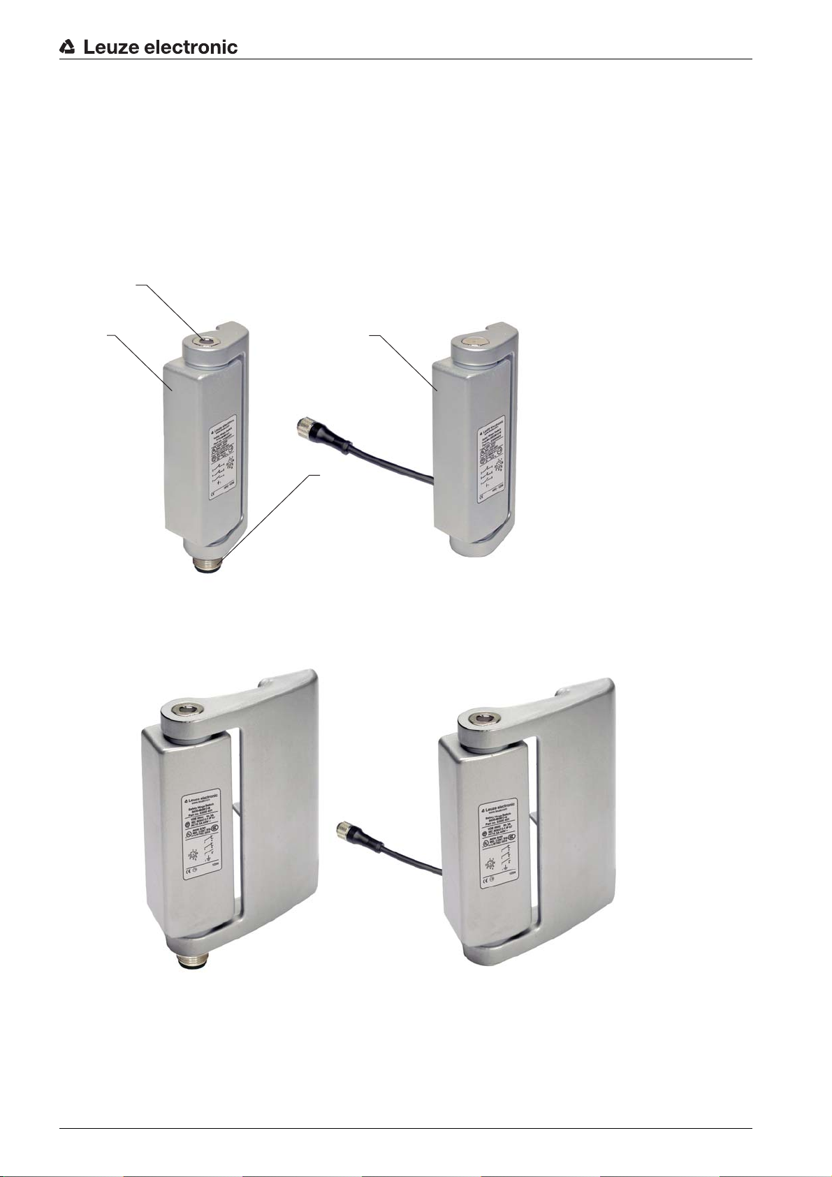
3.1 Device overview
The S400, S410 and S420 safety hinge switches are very compact and stable electro-mechanical
switching devices in a housing made of metal (stainless steel for the S420); the devices satisfy protection
rating IP 67 and IP 69K. The actuator is integrated into the housing. Depending on the version, electrical
connection is done either via a cable or a M12 plug with optional cable entry from above, below or on the
wall side (mounting side). This enables monitoring of all types of doors, hoods, flaps, etc. The opening
angle of the safety hinge switch is up to 180°. The switching angle is adjustable and can be adjusted
multiple times if necessary (e.g. misadjusted door).
Device description
1 Safety hinge switch
2 Cable entry or M12 plug
3 Opening for adjusting the switching angle
Figure 3.1: S400 safety hinge switch
Figure 3.2: S410 safety hinge switch
Leuze electronic S400 8
Page 9
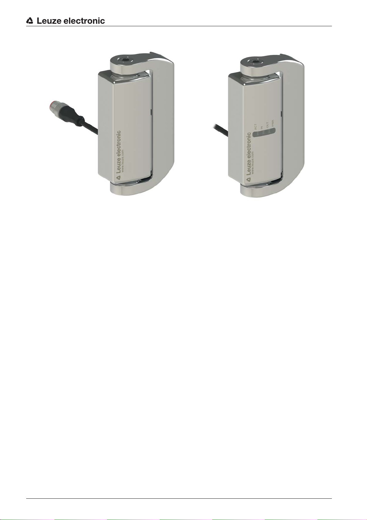
Device description
Figure 3.3: S420 safety hinge switch
The S400 series has a total width of 49 mm.
The S410 series has a total width of 79 mm.
The S420 series has a total width of 76 mm.
The M4 models are equipped with slow action contacts (2NC/1NO).
The M1 models are equipped with snap-action contacts (2NC/1NO).
The 9 models are equipped with slow action contacts (2NC/2NO).
The OS models are equipped with two safety-related switching outputs (OSSDs), two inputs and a signal
output.
Leuze electronic S400 9
Page 10
4 Functions
2
1
3
4
S400, S410 and S420 safety hinge switches are used as a mechanical hinges and simultaneously for posi-
tion monitoring of turning, bearing-mounted guards. The integrated safety contacts are force-opened as
soon as the preset switching angle is reached. As a result, the machine can only be switched on if the
protective device is closed.
In all models, the switching angle can be reset multiple times (e.g. when the door is misaligned) via the
protected adjusting screw. The covered screw mounting has a strong manipulation-resistant effect.
The S420 series satisfies strict requirements, e.g. in the food, pharmaceutical and cosmetic industries,
thanks to the stainless steel housing in accordance with safety class IP 67 and IP 69K with mechanical
load values up to 2000 N.
For the S420 series, versions are contact-supported or available with electronic inputs and OSSDs.
4.1 Special functions and performance characteristics of the S420-OSx series
• 2 electronic inputs
• 2 safety-related switching outputs (OSSDs)
• 1 signal output of actuator status
• Series connection of up to 32 S420-OSx
• Safety category 4, PL e, SIL CL 3
• Diagnosis display (LEDs) of operating voltage, self test, actuator status, OSSD status and input status
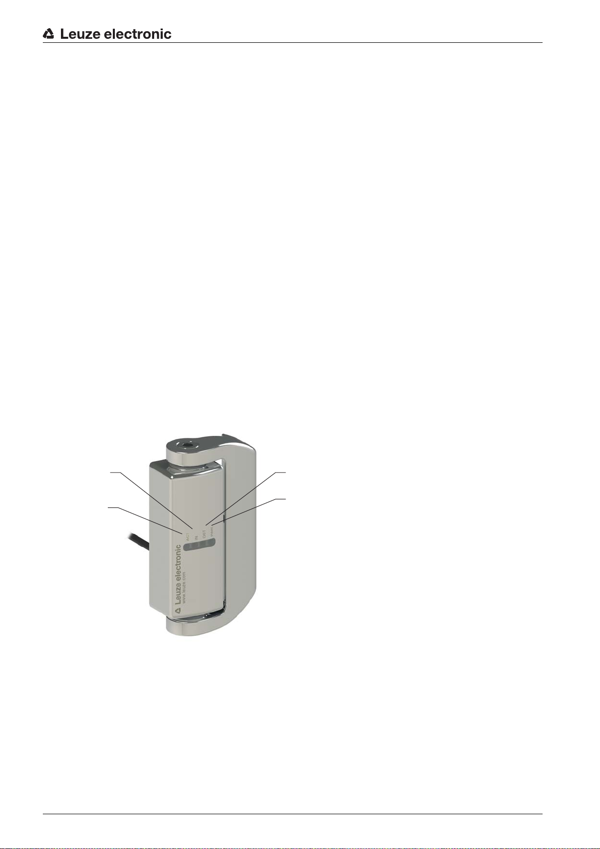
Functions
4.2 Display elements
1LED ACT
2LED IN
3LED OUT
4LED PWR
Leuze electronic S400 10
Page 11
Table 4.1: Meaning of the LEDs
Functions
LED PWR LED OUT LED IN LED ACT S420-OSx
off off off off off no
orange off off off U
green green green green operation yes yes on on monitored operation
green off green off operation no yes off off input condition fulfilled
green off off green operation yes no off on actuator detected, input condition not
green off off off operation no no off off actuator not detected, input condition
green off flashing
green off flashing
green green green flashing
green off off flashing
orange/
green
orange/
green
green operation yes irregular off on check and deactivate both input signals
green operation no irregular off off check and deactivate both input signals
orange/
green
orange/
green
status
switched onb) b) off off internal test mode
B
operation on the limit yes on off check actuator/realign door
operation on the limit no off on check and deactivate both input sig-
Actuator
detected
a)
OS1/
IN
b)
O3 Description
OS2
off off S420-OSx not switched on
fulfilled
not fulfilled
nals, test actuator/realign door
green off flashing
green red flash-
red off off off error (inter-
ing
orange/
green
off off error (out-
flashing
orange/
green
operation on the limit irregular off on check and deactivate both input sig-
put)
nal)
yes yes off off check for cross connection and short
b) b) off b) restart or exchange
nals, test actuator/realign door
circuit, restart
a) 2 input signals are present
b) irrelevant
Hinge switches of the S420 series with integrated OSSDs independently monitor the fulfillment of the input
condition and the redundancy of the actuator monitoring.
If one of the input signals is switched off, the S420-OSx switches both OSSDs off. Before activating the
OSSDs again, both input signals must be switched off and then reactivated.
In the event of very slow or minimal partial opening of the actuator, the S420-OSx switches both OSSDs
off. Before activating the OSSDs again, the actuator must be opened completely and then shut again.
In the event of fundamental errors (e.g. short circuit of the OSSDs) the diagnosis LEDs illuminate or blink
red. After trouble shooting and the following reset (switch-off of supply voltage), the S420-OSx switches
back to the normal operating mode.
Leuze electronic S400 11
Page 12

5 Applications
The safety hinge switch is suitable for e.g. the following protective devices:
• turning or swiveling moveable guards, flaps and hoods
• in environments with high dust concentration or high levels of particulate matter
• for stricter hygiene requirements (S420)
Applications
Leuze electronic S400 12
Page 13

6 Mounting
>180°
≤180°
1
2
3
3
2
WARNING
Severe accidents may result if the safety hinge switch is not mounted properly!
The protective function of the safety hinge switch is only ensured if correctly mounted and adjusted for
the respective, intended area of application.
Mounting may only be performed by competent personnel.
Observe standards, regulations and these instructions.
Protect the housing from materials penetrating the enclosure, consider environmental conditions (see
chapter 13 „Technical data“).
Use separate mechanical limit stop (see figure 6.1).
Set the switching angle so that the guard cannot be circumvented (e.g. by reaching around or walking
behind).
Test to ensure proper function.
6.1 Mounting the safety hinge switch
Prerequisites for mounting:
• M5 (M6 for S420) fastening screws of the correct length (see figure 6.1)
Mounting
1
2
5 / M 6
M
6+T
T
1 Frame (e.g. hollow chamber aluminum profile)
2 Safety hinge switch
Figure 6.1: Hinge mounts; length of the fastening screws = 6 + T mm
Wrong Correct
Figure 6.2: Mechanical limit stop (1) for the moving part of the protective device
Leuze electronic S400 13
1 Mechanical limit stop
2 Door
3Profile
Page 14

Figure 6.3: Maximum load of the S400 safety hinge switches
1000 N
max
1500 N
max
25 Nm
max
500 N
max
750 N
max
12 Nm
max
2000 N
max
2000 N
max
50 Nm
max
H/2H/2
H (100 min - 300 max)
F
max
D
300 max
F
max
(N)=25.000/D (mm)
max
Mounting
Figure 6.4: Maximum load of the S410 safety hinge switches
Figure 6.5: Maximum load of the S420 safety hinge switches
Select the mounting locations for safety hinge switches and additional hinges (if necessary) so that the
following conditions are satisfied:
• accessible to qualified personnel for testing and replacement
• form-fitting mounting is possible
Leuze electronic S400 14
Figure 6.6: Door with 1 safety hinge switch S400
F
Force exerted by door weight in N
max
D Distance from the center of gravity of the door to the hinge axis in mm
Page 15

F
H/8H/8 H/5H/1.81
H (300 min - 2500 MAX)
D
F
max
1000 max
F
max
(N)=250.000/D (mm)
max
H/2H/2
H (100 min - 300 max)
F
max
D
300 max
F
max
(N)=12.500/D (mm)
max
max
(N)=200.000/D (mm)
max
Mounting
D
H/1.66 H/5H/5
F
max
H (200 min - 1600 max)
800 max
F
Force exerted by door weight in N
max
D Distance from the center of gravity of the door to the hinge axis in mm
Figure 6.7: Door with 1 safety hinge switch S400 and 1 additional AC-H-S400 or AC-H-S400-S hinge
Leuze electronic S400 15
F
Force exerted by door weight in N
max
D Distance from the center of gravity of the door to the hinge axis in mm
Figure 6.8: Door with 1 safety hinge switch S400 and 2 additional AC-H-S400 or AC-H-S400-S hinges
F
Force exerted by door weight in N
max
D Distance from the center of gravity of the door to the hinge axis in mm
Figure 6.9: Door with 1 safety hinge switch S410
Page 16

F
F
max
(N)=100.000/D (mm)
max
H/1.66 H/5H/5
H (200 min - 1600 max)
D
F
max
800 max
F
max
(N)=200.000/D (mm)
max
H/8H/8 H/5H/1.81
H (300 min - 2500 MAX)
D
F
max
1000 max
H/2H/2
H (100 min - 500 max)
F
max
D
100 min - 500 max
A
Force exerted by door weight in N
max
D Distance from the center of gravity of the door to the hinge axis in mm
Figure 6.10: Door with 1 safety hinge switch S410 and 1 additional hinge AC-H-S410
Mounting
Leuze electronic S400 16
F
Force exerted by door weight in N
max
D Distance from the center of gravity of the door to the hinge axis in mm
Figure 6.11: Door with 1 safety hinge switch S410 and 2 additional hinges AC-H-S410
F
Force exerted by door weight in N
max
D Distance from the center of gravity of the door to the hinge axis in mm
Figure 6.12: Door with 1 safety hinge switch S420
Page 17

F
H/1.66 H/5H/5
H (200 min - 1600 max)
D
F
max
200 min - 1600 max
A
B
H/8H/8 H/5H/1.81
H (300 min - 2500 max)
D
F
max
200 min - 2000 max
A
B
B
Force exerted by door weight in N
max
D Distance from the center of gravity of the door to the hinge axis in mm
Figure 6.13: Door with 1 safety hinge switch S420 and 1 additional hinge AC-H-S420
Mounting
F
Force exerted by door weight in N
max
D Distance from the center of gravity of the door to the hinge axis in mm
Figure 6.14: Door with 1 safety hinge switch S420 and 2 additional hinges AC-H-S420
NOTICE
The safety hinge switch may be damaged if mounted improperly!
Screws that are too long or too short as well as faulty bore holes may damage the hinge.
Measure the length of the mounting screws exactly (see figure 6.1).
The position of the mounting bore holes should be exactly parallel to the profile axis.
Use only additional hinges from the respective series.
Prepare the bore holes for the safety hinge switch at the indicated positions (M5 or M6) (see chapter 3
„Device description“).
If necessary, prepare bore holes for additional hinges at the indicated positions (M5 or M6) (see
chapter 3 „Device description“).
If necessary, put seal underneath.
The axes of all hinges must align.
Leuze electronic S400 17
Screw down safety hinge switch and additional hinges with 2–3 Nm (M5) or 10–12 Nm (M6).
Page 18

Mounting
Set the switching angle of the safety hinge switch with a Phillips or flat-headed screwdriver (adjustment
range: maximum 1 turn for S400 and S410, maximum 1.5 turns for S420).
Provide limit stop at maximum opening angle (180°).
Test whether the guard can be circumvented; if necessary, readjust the switching angle (acc. to
EN ISO 13857).
WARNING
Failure of the switching function in the event of moisture, dust and tampering!
Always plug the opening for adjusting the switching angle.
Plug the opening for adjusting the switching angle with the sealing plug (see figure 6.15).
Leuze electronic S400 18
Page 19

Figure 6.15: Sealing plug AC-SEPL-S4xx
The S420 series includes a cloth for cleaning after mounting.
Mounting
Leuze electronic S400 19
Page 20

7 Electrical connection
WARNING
Serious accidents may result if the electrical connection is faulty!
Electrical connection may only be performed by competent and authorized personnel.
7.1 Connecting the contact block
Prerequisites:
• temperature stability of the cable insulation material must be greater than the maximum temperature
of the housing (see chapter 13 „Technical data“)
• connection via protected wiring
• maximum current load is observed (see chapter 13 „Technical data“)
• Take electrostatic precautionary measures (ESD) before handling the S420-OSx.
• Only operate the safety-related chain with separate 24 V current supply (SELV).
3
Electrical connection
7
5
3
7
5
6
4
8
6
4
8
Figure 7.1: Contact block 2NC + 1NO (S400-M4xxx, S410-M4xxx with slow action contacts. S400-
M1xxx, S410-M1xxx with snap-action contact)
4
3
2
1
7
6
5
8
Figure 7.2: OSSD contact block versions (S420-OSx)
DANGER
Risk of death by electric shock!
Interrupt the voltage supply to the safety hinge switch.
Connect the contact block according to the application-specific circuit diagram.
Provide NC contacts ( ) for looping into the safety circuit.
If current limiting is not provided for safety-related contacts, upstream fuses must be present.
Avoid over-tightening, bending or stretching the cables.
Leuze electronic S400 20
Page 21

Electrical connection
BK
BKWH
RD
RDWH
BN
BU
GNYE
3
4
1
7
8
2
6
5
BK = black
WH = white
RD = red
BN = brown
BU = blue
GN = green
YE = yellow/green)
Figure 7.3: Assignments of connecting cables S400-M4CB2-B, S400-M4CB2-T, S400-M4-CB2PUR-W,
S410-M1CB2-B, S410-M1CB2-T and S410-M4-CB2PUR-W
3
4
5
6
7
8
1
1
7
6
2
5
3
4
8
Figure 7.4: Assignments of 8-pin M12 plugs S400-M4M12-B, S400-M4M12-T, S400-M4-CB02M12-W,
S400-M1-CB02M12-W, S410-M1M12-B, S410-M1M12-T and S410-M4-CB02M12-W
Figure 7.5: Pin assignment S420-9x, S420-OSx
Table 7.1: Pin assignment/core colors S420-9x
Pin Wire color Assignment
1black NC 1
2 black/white NC 1
3red NC 2
4 red/white NC 2
5brown NO 1
6blue NO 1
7violet NO 2
8 violet/white NO 2
Leuze electronic S400 21
Shield yellow/green FE - functional earth, shield
Page 22

Table 7.2: Pin assignment/core colors S420-OSx
S400-M4M12-B S400-M4M12-B
Var . B
Var . A
MSI-SR4B
0V
-K3
-A2-A1 -A3
-K4
-K4
-K3
0V
PE PE
0V
13 23 41A1 S22 S12 S31 S33 S34 S35
33
-K3
-K4
+24V
2 AOPD-
1 AOPD+
2 AOPD+
IV-0
RES-0
RES-I
543 6 7 8
543 6 7 8
A2 14 24 42
A1
A2
-K3
L- L-
34
*
A1
A2
-K4
*
1
2
1
2
L+ L+
+24V +24V
1
2
1
2
1
2
-S1
Pin Wire color Assignment
1brown A1
2red IS1
3blue A2
4 red/white OS1
5black O3
6violet IS2
7 black/white OS2
8 violet/white n.c.
Electrical connection
* Spark extinction circuit, suitable spark extinction provided
Figure 7.6: Connection example S400-M4M12-B
Leuze electronic S400 22
Page 23

Electrical connection
+24V
0V
+24V
+24V
T0
I1
PE
0V
0V
I0
0V
0V
A1
PE
+24V
T1
0V
A2
-H1
I2
I5
I4
I10I8
I11
I9
I3
I6
I7
M0T0
A1
A2
-K1
A1
A2
-K2
O1-
O0-
O3
O1
O0
O2
-A1
ESB200
2/1
1/2
1/1
2/2
S400-M4M12-B
543 6 7 8
-A3
MSI 100
S420-OSx
IS2IS1A1 A2
O3OS2OS1
S420-OSx
IS2IS1A1 A2
O3OS2OS1
S420-OSx
IS2IS1A1 A2
O3OS2OS1
T1
-H2
-H3
-H4
-A2
-A3
Figure 7.7: Connection example S420-OSx
Leuze electronic S400 23
Page 24

8 Starting up the device
WARNING
Improper commissioning may result in serious injury
Commissioning may only be performed by competent and authorized personnel
Prerequisites:
• Safety hinge switch is mounted, adjusted, plugged and connected according to these instructions
• operating personnel have been trained in the correct use
Test the function of the safety hinge switch (see chapter 9 „Testing“).
The safety hinge switch is then ready for use.
Starting up the device
Leuze electronic S400 24
Page 25

9 Testing
WARNING
Severe accidents may result if tests are not performed properly!
Tests may only be performed by competent and authorized personnel
S400, S410 and S420 safety hinge switches are maintenance-free.
For the testing intervals, observe nationally applicable regulations.
Document all tests in a comprehensible manner.
9.1 To be performed prior to the initial start-up by competent personnel
Check whether the safety hinge switch is operated according to its specified environmental conditions
(see chapter 13 „Technical data“).
Test to ensure proper mechanical and electrical function (see chapter 9.2 „To be performed periodically
by competent personnel“).
9.2 To be performed periodically by competent personnel
Mechanical function
Stop the dangerous state.
Check that the components are securely fastened.
Test the cable entry for leaks and check that the opening for setting the switching angle is plugged.
Check safety hinge switch and cable entry for damage, deposits, deformation and wear.
Open and close the protective device several times, testing the ease of movement while doing so.
Testing
Electrical function
WARNING
Severe accidents may result if tests are not performed properly!
Make certain that there are no persons in the danger zone.
Stop the dangerous state and open the protective device.
Make certain that the machine cannot be started while the protective door is open.
Close the protective door and start the machine.
Test several times whether the machine stops upon opening of the protective door.
Make certain that the guard cannot be circumvented and that the switching angle is set to a sufficiently
small value (EN ISO 13857).
Test whether the dangerous state ends before the point of operation can be reached (EN ISO 13855).
9.3 To be performed daily by the operating personnel
WARNING
Severe accidents may result if tests are not performed properly!
Make certain that there are no persons in the danger zone.
Stop the dangerous state and open the protective device.
Check the safety hinge switch and cable entry for damage or tampering.
Test the cable entry for leaks and check that the opening for setting the switching angle is plugged with
the original plug.
Make certain that the machine cannot be started while the protective device is open.
Close the protective device and start the machine.
Test whether the machine stops upon opening of the protective device.
Leuze electronic S400 25
Page 26

10 Cleaning
There must be no soiling (e.g moisture and dust), especially at the joints of the safety hinge switch and the
area near the sealing plug (switching angle adjustment).
Prerequisites for regular cleaning:
• machine is switched off
• voltage supply to the safety switch is interrupted
Clean the safety hinge switch (e.g. with a vacuum cleaner).
Cleaning
Leuze electronic S400 26
Page 27

11 Disposing
The nationally valid regulations for electro-mechanical components are to be observed when disposing.
Disposing
Leuze electronic S400 27
Page 28

12 Service and support
Telephone number for 24-hour standby service:
+49 (0) 7021 573-0
Service hotline:
+49 (0) 8141 5350-111
Monday to Thursday, 8.00 a.m. to 5.00 p.m. (UTC+1)
Friday, 8.00 a.m. to 4.00 p.m. (UTC +1)
E-mail:
service.protect@leuze.de
Return address for repairs:
Service Center
Leuze electronic GmbH + Co. KG
In der Braike 1
D-73277 Owen / Germany
Service and support
Leuze electronic S400 28
Page 29

13 Technical data
Table 13.1: General technical data
Switch type Interlock device without guard interlocking in accor-
SIL in accordance with IEC 61508:2010 SIL 3
SILCL in accordance with IEC/EN 62061:2005 SILCL 3
Technical data
dance with EN 1088
Performance Level (PL) in accordance with
PL e
EN ISO 13849-1:2008
Category in accordance with EN ISO 13849-
Cat. 4
1:2008
Internal actuator Safety switch in hinge, encapsulated
Max. load S400-xxx:
axial: 1500 N
radial: 1000 N
torsional: 25 Nm
S410-xxx:
axial: 750 N
radial: 500 N
torsional: 12 Nm
S420-xxx:
axial: 2000 N
radial: 2000 N
torsional: 50 Nm
Actuation speed min. 2°/s, max. 90°/s
Actuation angle max. 180°
Actuating path with forced separation min. +4° (from switching point)
min. +6° (from switching point), (S420-9xx)
Mechanical life time in accordance with EN/
6
10
switching cycles
IEC 60947-5-1
Actuation frequency according to EN/
IEC 60947-5-1
Service life (T
) in accordance with EN ISO
M
max. 720 per hour
max. 600 per hour(S420-xxx)
20 years
13849-1:2008
Number of cycles before dangerous failure (B10
)
d
5,000,000
according to EN 61810-2
Usage category according to EN/IEC 60947-5-1 AC 15 / DC 13: U
24 V, Ie 2 A
e
Dimensions (dimensional drawings) see chapter 3 „Device description“
Table 13.2: Safety
Protection class IP 67, IP 69K
Contact allocation 2NC + 1NO
2NC + 2NO (S420-9xx)
Contact material silver alloy, solid
Leuze electronic S400 29
Page 30

Switching principle S400-M4x: slow-action contact
S410-M4x: slow-action contact
S400-M1x: snap-action contact
S410-M1x: snap-action contact
S420-9x: slow-action contact
S420-OSx: PNP
Contact opening Force-fit
Rated insulation voltage 30 V AC, 36 V DC
Conventional thermal current max. 2 A
Short-circuit protection according to IEC 60269-1 2 A, 500 V, type gG
Table 13.3: Electrical characteristics S420-OSx
Technical data
Supply voltage U
B
24 V DC, -15 % … +10 %
Switchable load per OSSD, max. 6 W
Power consumption < 1 W
Rated impulse withstand voltage U
imp
1.5 kV
Overvoltage category III
Inputs IS1/IS2
Absorbed switching current per input 5 mA
Safe outputs OS1/OS2
Cutoff voltage U
e
24 V DC
Output type PNP
Switched current per OSSD, max. 0.25 A
Short-circuit indicator Yes
Overcurrent protected Yes
Switch-off test pulses < 300
s
Permissible capacitance between two outputs < 200 nF
Permissible capacitance between outputs and
< 200 nF
ground
Signal outputs O3
Output type PNP
Max. switched current 0.1 A
Short-circuit indicator No
Overcurrent protected Yes
Table 13.4: Housing
Housing material metal
stainless steel, AISI 316L (S420-xxx)
Surface roughness R
Leuze electronic S400 30
(S420) < 0,8 m
a
Page 31

Table 13.5: Connection
Number of cable entries 1
Connection type 2 m PVC cable:
S400-M4CB2-B
S400-M4CB2-T
S410-M1CB2-B
S410-M1CB2-T
S420-9CB2-LW
S420-OS-CB2-LW
2 m PUR cable:
S400-M4-CB2PUR-W
S410-M4-CB2PUR-W
M12 plug:
S400-M4M12-B
S400-M4M12-T
S410-M1M12-B
S410-M1M12-T
Technical data
0.2 m PVC cable with M12 plug:
S400-M4-CB02M12-W
S400-M1-CB02M12-W
S410-M4-CB02M12-W
S420-9-CB02M12-LW
S420-OS-CB02M12-LW
Conductor cross-section (stranded) S400-M4CB2-B: 7 x 0.5 mm
S400-M4CB2-T: 7 x 0.5 mm
S410-M1CB2-B: 7 x 0.5 mm
2
2
2
Cable routing side S400-xxx-B: floor-side with left installation
S410-xxx-B: floor-side with left installation
S400-xxx-T: from above with left installation
S410-xxx-T: from above with left installation
S400-xxx-W: wall side mounting
S410-xxx-W: wall side mounting
Table 13.6: Timing
Reaction time, input signal shutoff, typ. 7 ms
Reaction time, input signal shutoff, max. 12 ms
Reaction time, actuator switching point, typ. 7 ms
Reaction time, actuator switching point, max. 12 ms
Table 13.7: Environment
Temperature range, operation -25 … +80 °C
-25 … +70 °C (S420-OSx)
Dirt level, external,
3
according to EN/IEC 60947-1
Leuze electronic S400 31
Page 32

Technical data
27
71
17
M5
M5
30
100.6
81
7
49
12
22.5
22.5
27
71
17
M5
M5
30
100.6
81
7
49
12
17
M5
M5
71
27
30
81
M12x1
10.5100.6
12
7
49
22.5
13.1 Dimensions
30
17
M5
71
81
100.6
M5
10.5
M 12 x1
12
22.5
Figure 13.1: Dimensions of S400-M4CB2-B in mmFigure 13.2: Dimensions of S400-M4M12-B in mm
27
7
49
Figure 13.3: Dimensions of S400-M4CB2-T in
Figure 13.4: Dimensions of S400-M4M12-T in mm
mm
Leuze electronic S400 32
Page 33

100.6
27
71
17
M5
16.5
M
5
30
100.6
81
7
49
12
22.5
8.9
31.4
Ø12
17
71
50
M5
M5
30
81
100.6
14
79
12
22.5
21
6.5
17
71
50
M5
M5
30
81
100.6
M12 x 1
14
79
12
22.5
21
6.5
71
M5
M5
50
81
100.6
17
30
1421
12
22.5
6.5
79
71
M5
M 5
81
100.6
M
12 x 1
50
17
30
10.5
1421
12
22.5
6.5
79
31.4
81
22.5
Technical data
30
17
M5
M 5
71
16.5
27
12
Ø
8.9
12
7
49
Figure 13.5: Dimensions of S400-Mx-
CB02M12-W in mm
Figure 13.7: Dimensions of S410-M1CB2-B in
mm
Figure 13.6: Dimensions of S400-M4-CB2PUR-W in
mm
Figure 13.8: Dimensions of S410-M1M12-B in mm
Figure 13.9: Dimensions of S410-M1CB2-T
Leuze electronic S400 33
in mm
Figure 13.10:Dimensions of S410-M1M12-T in mm
Page 34

Figure 13.11:Dimensions of S410-M4-
17
71
50
M5
16.5
M5
30
81
100.6
14
79
12
22.5
21
6.5
Ø
12
8.9
15.5
31.5
76
14 22
6.5
6
Ø12
40
29 26.5 9
==
88
6
M6
M6
M6
21.5
99.4
50
126
15.5
31.5
76
14 22
6.5
6
Ø12
40
29 26.5 9
==
88
6
M6
M6
M 6
21.5
99.4
50
126
CB02M12-W and S410-M4CB2PUR-W in mm
Technical data
Figure 13.12:Dimensions of S420-9CB2-LW
and S420-OS-CB2-LW in mm
Figure 13.13:Dimensions of S420-9-CB02M12-LW
and S420-OS-CB02M12-LW in mm
Leuze electronic S400 34
Page 35

14 Ordering information and accessories
Table 14.1: S400, S410 and S420 safety hinge switches
Part no. Article Description
63000400 S400-M4CB2-B 2 m PVC cable, cable entry at bottom (with left installation)
63000401 S400-M4M12-B 8-pin M12 plug, cable entry at bottom (with left installation)
63000402 S400-M4CB2-T 2 m PVC cable, cable entry at top (with left installation)
63000403 S400-M4M12-T 8-pin M12 plug, cable entry at top (with left installation)
63000406 S400-M4-CB02M12-W 0.2 m PVC cable with 8-pin M12 plug, cable entry at wall side
63000407 S400-M1-CB02M12-W 0.2 m PVC cable with 8-pin M12 plug, cable entry at wall side
63000411 S400-M4-CB2PUR-W 2 m PUR cable, cable entry at wall side
63000404 S410-M1CB2-B 2 m PVC cable, cable entry at bottom (with left installation),
total width 79 mm
63000405 S410-M1M12-B 8-pin M12 plug, cable entry at bottom (with left installation),
total width 79 mm
Ordering information and accessories
63000408 S410-M1CB2-T 2 m PVC cable, cable entry at top (with left installation)
63000409 S410-M1M12-T 8-pin M12 plug, cable entry at top (with left installation)
63000410 S410-M4-CB02M12-W 0.2 m PVC cable with 8-pin M12 plug, cable entry at wall side
63000412 S410-M4-CB2PUR-W 2 m PUR cable, cable entry at wall side
63000420 S420-9CB2-LW Stainless steel, 2 m PVC cable, cable entry at wall side (with
63000421 S420-OS-CB2-LW Stainless steel, 2 safety-related switching outputs, 2 m PVC
63000422 S420-9-CB02M12-LW Stainless steel, 0.2 m PVC cable with 8-pin M12 plug, cable
63000423 S420-OS-CB02M12-LW Stainless steel, 2 safety-related switching outputs, 0.2 m PVC
14.1 Accessories
Table 14.2: Accessories for the safety hinge switches S400, S410 and S420
left installation), total width 76 mm
cable, cable entry at wall side (with left installation), total width
76 mm
entry at wall side (with left installation), total width 76 mm
cable with 8-pin M12 plug, cable entry at wall side (with left
installation), total width 76 mm
Article Part no. Description
AC-H-S400 63000770 Additional hinge for S400 safety hinge switch
AC-H-S400-S 63000775 Additional hinge, small for the S400 safety hinge switch
AC-MP3-S400 63000771 Mounting plate set, flat, long version, for S400 safety hinge
switch
AC-MP1-S400 63000772 Mounting plate set, angled, long version, for S400 safety hinge
switch
AC-H-S410 63000773 Additional hinge for S410 safety hinge switch
Leuze electronic S400 35
Page 36

Ordering information and accessories
M5
M5
35
27
21
45
65
7
44.5
12
22.5
Article Part no. Description
AC-H-S420 63000778 Additional hinge for S420 safety hinge switch
AC-S-S420 63000779 Seal set between S420 safety hinge switch and mounting posi-
tion
AC-SEPL-S4xx 63000774 Safety plug for safety hinge switch S4xx
CB-M12-5000E-8GF 678060 PUR, 8-pin, 5 m, shielded, M12 coupling, straight, prefabri-
cated on one end
CB-M12-10000E-8GF 678061 PUR, 8-pin, 10 m, shielded, M12 coupling, straight, prefabri-
cated on one end
CB-M12-15000E-8GF 678062 PUR, 8-pin, 15 m, shielded, M12 coupling, straight, prefabri-
cated on one end
CB-M12-25000E-8GF 678063 PUR, 8-pin, 25 m, shielded, M12 coupling, straight, prefabri-
cated on one end
30
17
M5
71
81
100.6
M5
27
7
12
22.5
49
Figure 14.1: Dimensions of AC-H-S400 additional
hinge in mm
Figure 14.2: Dimensions of AC-H-S400-S additional
hinge in mm
Leuze electronic S400 36
Page 37

Ordering information and accessories
71
50
M5
M5
17
81
100,6
30
1421
12
22,5
79
6,5
Figure 14.3: Dimensions of AC-H-S410 additional
hinge in mm
126
31.5
99.4
15.5
29 26.5 9
M6
88
50
14 22
40
76
M 6
M6
6
==
6.5
Figure 14.4: Dimensions of AC-H-S420 additional
hinge in mm
Leuze electronic S400 37
Page 38

15 EC Declaration of Conformity
Leuze electronic GmbH + Co. KG
In der Braike 1
D-73277 Owen
Telefon +49 (0) 7021 573-0
Telefax +49 (0) 7021 573-199
www.leuze.com
Leuze electronic GmbH + Co. KG, Sitz Owen, Registergericht Stuttgart, HRA 230712
Persönlich haftende Gesellschafterin Leuze electronic Geschäftsführungs-GmbH,
Sitz Owen, Registergericht Stuttgart, HRB 230550
Geschäftsführer: Ulrich Balbach
USt.-IdNr. DE 145912521 │ Zollnummer 2554232
Es gelten ausschließlich unsere aktuellen Verkaufs- und Lieferbedingungen
Only our current Terms and Conditions of Sale and Delivery shall apply
Nr. 609340-2014/07
EG-KONFORMITÄTS-
ERKLÄRUNG
(ORIGINAL)
EC DECLARATION OF
CONFORMITY
(ORIGINAL)
DECLARATION CE DE
CONFORMITE
(ORIGINAL)
Der Hersteller The Manufacturer Le constructeur
Leuze electronic GmbH + Co. KG
In der Braike 1, PO Box 1111
73277 Owen, Germany
erklärt, dass die nachfolgend
aufgeführten Produkte den einschlägigen Anforderungen der
genannten EG-Richtlinien und
Normen entsprechen.
declares that the following listed
products full the relevant provisions of the mentioned EC Directives and standards.
déclare que les produits identiés
suivants sont conformes aux
directives CE et normes mentionnées.
Produktbeschreibung: Description of product: Description de produit:
Sicherheits-Schalter
S20, S200, S300, S400, S410, S420
Sicherheits-Zuhaltung
L10, L100, L200
NOT-HALT-Befehlsgerät
ERS200
Seriennummer siehe Typschild
Safety Switch
S20, S200, S300, S400, S410, S420
Safety Locking Device
L10, L100, L200
E-STOP command device
ERS200
Serial no. see name plates
Interrupteur de sécurité
S20, S200, S300, S400, S410, S420
Interverrouillage de sécurité
L10, L100, L200
Appareil de commande d'ARRÊT
D'URGENCE
ERS200
N° série voir plaques signalétiques
Angewandte EG-Richtlinie(n): Applied EC Di rective(s): Directive(s) CE appliquées:
2006/42/EG 2006/42/EC 2006/42/CE
2004/108/EG 2004/108/EC 2004/108/CE
2006/95/EG 2006/95/EC 2006/95/CE
Angewandte Normen: Applied standards: Normes appliquées:
EN/IEC 60947-5-1; EN ISO 13849-1; EN 1088
Benannte Stelle /
Baumusterprüfbescheinigung:
Notied Body /
Certicate of Type Examination:
Organisme notié /
Attestation d'examen CE de type:
IMQ S.p.A.
Istituto Italiano Del Marchio Di Qualitá
Via Quintiliano 43
I-20138 Milano
/
CAO2.03747(S20); CAO2.03748 (L100) );
CAO2.04212 (L200); CAO2.03749 (S200, S300);
CAO2.03756 (S400); CAO2.03749 (ERS200, L10-M);
CAO2.03750 (L10-P)
Bevollmächtigter für die Zusam-
menstellung der technischen
Unterlagen:
Authorized person to compile the
technical le:
Personne autorisée à constituer
le dossier technique:
André Thieme; Leuze electronic GmbH + Co. KG
Liebigstr. 4; 82256 Fuerstenfeldbruck; Germany
Owen, 02.07.2014
Datum / Date / Date
Ulrich Balbach, Geschäftsführer / Director / Directeur
EC Declaration of Conformity
Leuze electronic S400 38
 Loading...